WO2024257272A1 - ハーネスの取付構造 - Google Patents
ハーネスの取付構造 Download PDFInfo
- Publication number
- WO2024257272A1 WO2024257272A1 PCT/JP2023/022104 JP2023022104W WO2024257272A1 WO 2024257272 A1 WO2024257272 A1 WO 2024257272A1 JP 2023022104 W JP2023022104 W JP 2023022104W WO 2024257272 A1 WO2024257272 A1 WO 2024257272A1
- Authority
- WO
- WIPO (PCT)
- Prior art keywords
- harness
- vehicle
- unit
- battery unit
- drive unit
- Prior art date
- Legal status (The legal status is an assumption and is not a legal conclusion. Google has not performed a legal analysis and makes no representation as to the accuracy of the status listed.)
- Ceased
Links
Images
Classifications
-
- B—PERFORMING OPERATIONS; TRANSPORTING
- B60—VEHICLES IN GENERAL
- B60K—ARRANGEMENT OR MOUNTING OF PROPULSION UNITS OR OF TRANSMISSIONS IN VEHICLES; ARRANGEMENT OR MOUNTING OF PLURAL DIVERSE PRIME-MOVERS IN VEHICLES; AUXILIARY DRIVES FOR VEHICLES; INSTRUMENTATION OR DASHBOARDS FOR VEHICLES; ARRANGEMENTS IN CONNECTION WITH COOLING, AIR INTAKE, GAS EXHAUST OR FUEL SUPPLY OF PROPULSION UNITS IN VEHICLES
- B60K1/00—Arrangement or mounting of electrical propulsion units
-
- B—PERFORMING OPERATIONS; TRANSPORTING
- B60—VEHICLES IN GENERAL
- B60K—ARRANGEMENT OR MOUNTING OF PROPULSION UNITS OR OF TRANSMISSIONS IN VEHICLES; ARRANGEMENT OR MOUNTING OF PLURAL DIVERSE PRIME-MOVERS IN VEHICLES; AUXILIARY DRIVES FOR VEHICLES; INSTRUMENTATION OR DASHBOARDS FOR VEHICLES; ARRANGEMENTS IN CONNECTION WITH COOLING, AIR INTAKE, GAS EXHAUST OR FUEL SUPPLY OF PROPULSION UNITS IN VEHICLES
- B60K1/00—Arrangement or mounting of electrical propulsion units
- B60K1/04—Arrangement or mounting of electrical propulsion units of the electric storage means for propulsion
-
- B—PERFORMING OPERATIONS; TRANSPORTING
- B60—VEHICLES IN GENERAL
- B60L—PROPULSION OF ELECTRICALLY-PROPELLED VEHICLES; SUPPLYING ELECTRIC POWER FOR AUXILIARY EQUIPMENT OF ELECTRICALLY-PROPELLED VEHICLES; ELECTRODYNAMIC BRAKE SYSTEMS FOR VEHICLES IN GENERAL; MAGNETIC SUSPENSION OR LEVITATION FOR VEHICLES; MONITORING OPERATING VARIABLES OF ELECTRICALLY-PROPELLED VEHICLES; ELECTRIC SAFETY DEVICES FOR ELECTRICALLY-PROPELLED VEHICLES
- B60L3/00—Electric devices on electrically-propelled vehicles for safety purposes; Monitoring operating variables, e.g. speed, deceleration or energy consumption
- B60L3/0007—Measures or means for preventing or attenuating collisions
-
- B—PERFORMING OPERATIONS; TRANSPORTING
- B60—VEHICLES IN GENERAL
- B60L—PROPULSION OF ELECTRICALLY-PROPELLED VEHICLES; SUPPLYING ELECTRIC POWER FOR AUXILIARY EQUIPMENT OF ELECTRICALLY-PROPELLED VEHICLES; ELECTRODYNAMIC BRAKE SYSTEMS FOR VEHICLES IN GENERAL; MAGNETIC SUSPENSION OR LEVITATION FOR VEHICLES; MONITORING OPERATING VARIABLES OF ELECTRICALLY-PROPELLED VEHICLES; ELECTRIC SAFETY DEVICES FOR ELECTRICALLY-PROPELLED VEHICLES
- B60L50/00—Electric propulsion with power supplied within the vehicle
- B60L50/50—Electric propulsion with power supplied within the vehicle using propulsion power supplied by batteries or fuel cells
- B60L50/51—Electric propulsion with power supplied within the vehicle using propulsion power supplied by batteries or fuel cells characterised by AC-motors
-
- B—PERFORMING OPERATIONS; TRANSPORTING
- B60—VEHICLES IN GENERAL
- B60L—PROPULSION OF ELECTRICALLY-PROPELLED VEHICLES; SUPPLYING ELECTRIC POWER FOR AUXILIARY EQUIPMENT OF ELECTRICALLY-PROPELLED VEHICLES; ELECTRODYNAMIC BRAKE SYSTEMS FOR VEHICLES IN GENERAL; MAGNETIC SUSPENSION OR LEVITATION FOR VEHICLES; MONITORING OPERATING VARIABLES OF ELECTRICALLY-PROPELLED VEHICLES; ELECTRIC SAFETY DEVICES FOR ELECTRICALLY-PROPELLED VEHICLES
- B60L50/00—Electric propulsion with power supplied within the vehicle
- B60L50/50—Electric propulsion with power supplied within the vehicle using propulsion power supplied by batteries or fuel cells
- B60L50/60—Electric propulsion with power supplied within the vehicle using propulsion power supplied by batteries or fuel cells using power supplied by batteries
-
- B—PERFORMING OPERATIONS; TRANSPORTING
- B60—VEHICLES IN GENERAL
- B60L—PROPULSION OF ELECTRICALLY-PROPELLED VEHICLES; SUPPLYING ELECTRIC POWER FOR AUXILIARY EQUIPMENT OF ELECTRICALLY-PROPELLED VEHICLES; ELECTRODYNAMIC BRAKE SYSTEMS FOR VEHICLES IN GENERAL; MAGNETIC SUSPENSION OR LEVITATION FOR VEHICLES; MONITORING OPERATING VARIABLES OF ELECTRICALLY-PROPELLED VEHICLES; ELECTRIC SAFETY DEVICES FOR ELECTRICALLY-PROPELLED VEHICLES
- B60L50/00—Electric propulsion with power supplied within the vehicle
- B60L50/50—Electric propulsion with power supplied within the vehicle using propulsion power supplied by batteries or fuel cells
- B60L50/60—Electric propulsion with power supplied within the vehicle using propulsion power supplied by batteries or fuel cells using power supplied by batteries
- B60L50/64—Constructional details of batteries specially adapted for electric vehicles
-
- B—PERFORMING OPERATIONS; TRANSPORTING
- B60—VEHICLES IN GENERAL
- B60L—PROPULSION OF ELECTRICALLY-PROPELLED VEHICLES; SUPPLYING ELECTRIC POWER FOR AUXILIARY EQUIPMENT OF ELECTRICALLY-PROPELLED VEHICLES; ELECTRODYNAMIC BRAKE SYSTEMS FOR VEHICLES IN GENERAL; MAGNETIC SUSPENSION OR LEVITATION FOR VEHICLES; MONITORING OPERATING VARIABLES OF ELECTRICALLY-PROPELLED VEHICLES; ELECTRIC SAFETY DEVICES FOR ELECTRICALLY-PROPELLED VEHICLES
- B60L50/00—Electric propulsion with power supplied within the vehicle
- B60L50/50—Electric propulsion with power supplied within the vehicle using propulsion power supplied by batteries or fuel cells
- B60L50/60—Electric propulsion with power supplied within the vehicle using propulsion power supplied by batteries or fuel cells using power supplied by batteries
- B60L50/66—Arrangements of batteries
-
- B—PERFORMING OPERATIONS; TRANSPORTING
- B60—VEHICLES IN GENERAL
- B60R—VEHICLES, VEHICLE FITTINGS, OR VEHICLE PARTS, NOT OTHERWISE PROVIDED FOR
- B60R16/00—Electric or fluid circuits specially adapted for vehicles and not otherwise provided for; Arrangement of elements of electric or fluid circuits specially adapted for vehicles and not otherwise provided for
- B60R16/02—Electric or fluid circuits specially adapted for vehicles and not otherwise provided for; Arrangement of elements of electric or fluid circuits specially adapted for vehicles and not otherwise provided for electric constitutive elements
- B60R16/0207—Wire harnesses
- B60R16/0215—Protecting, fastening and routing means therefor
-
- B—PERFORMING OPERATIONS; TRANSPORTING
- B60—VEHICLES IN GENERAL
- B60K—ARRANGEMENT OR MOUNTING OF PROPULSION UNITS OR OF TRANSMISSIONS IN VEHICLES; ARRANGEMENT OR MOUNTING OF PLURAL DIVERSE PRIME-MOVERS IN VEHICLES; AUXILIARY DRIVES FOR VEHICLES; INSTRUMENTATION OR DASHBOARDS FOR VEHICLES; ARRANGEMENTS IN CONNECTION WITH COOLING, AIR INTAKE, GAS EXHAUST OR FUEL SUPPLY OF PROPULSION UNITS IN VEHICLES
- B60K1/00—Arrangement or mounting of electrical propulsion units
- B60K1/04—Arrangement or mounting of electrical propulsion units of the electric storage means for propulsion
- B60K2001/0405—Arrangement or mounting of electrical propulsion units of the electric storage means for propulsion characterised by their position
- B60K2001/0416—Arrangement in the rear part of the vehicle
-
- B—PERFORMING OPERATIONS; TRANSPORTING
- B60—VEHICLES IN GENERAL
- B60K—ARRANGEMENT OR MOUNTING OF PROPULSION UNITS OR OF TRANSMISSIONS IN VEHICLES; ARRANGEMENT OR MOUNTING OF PLURAL DIVERSE PRIME-MOVERS IN VEHICLES; AUXILIARY DRIVES FOR VEHICLES; INSTRUMENTATION OR DASHBOARDS FOR VEHICLES; ARRANGEMENTS IN CONNECTION WITH COOLING, AIR INTAKE, GAS EXHAUST OR FUEL SUPPLY OF PROPULSION UNITS IN VEHICLES
- B60K1/00—Arrangement or mounting of electrical propulsion units
- B60K1/04—Arrangement or mounting of electrical propulsion units of the electric storage means for propulsion
- B60K2001/0405—Arrangement or mounting of electrical propulsion units of the electric storage means for propulsion characterised by their position
- B60K2001/0422—Arrangement under the front seats
-
- B—PERFORMING OPERATIONS; TRANSPORTING
- B60—VEHICLES IN GENERAL
- B60K—ARRANGEMENT OR MOUNTING OF PROPULSION UNITS OR OF TRANSMISSIONS IN VEHICLES; ARRANGEMENT OR MOUNTING OF PLURAL DIVERSE PRIME-MOVERS IN VEHICLES; AUXILIARY DRIVES FOR VEHICLES; INSTRUMENTATION OR DASHBOARDS FOR VEHICLES; ARRANGEMENTS IN CONNECTION WITH COOLING, AIR INTAKE, GAS EXHAUST OR FUEL SUPPLY OF PROPULSION UNITS IN VEHICLES
- B60K1/00—Arrangement or mounting of electrical propulsion units
- B60K1/04—Arrangement or mounting of electrical propulsion units of the electric storage means for propulsion
- B60K2001/0405—Arrangement or mounting of electrical propulsion units of the electric storage means for propulsion characterised by their position
- B60K2001/0433—Arrangement under the rear seats
-
- B—PERFORMING OPERATIONS; TRANSPORTING
- B60—VEHICLES IN GENERAL
- B60K—ARRANGEMENT OR MOUNTING OF PROPULSION UNITS OR OF TRANSMISSIONS IN VEHICLES; ARRANGEMENT OR MOUNTING OF PLURAL DIVERSE PRIME-MOVERS IN VEHICLES; AUXILIARY DRIVES FOR VEHICLES; INSTRUMENTATION OR DASHBOARDS FOR VEHICLES; ARRANGEMENTS IN CONNECTION WITH COOLING, AIR INTAKE, GAS EXHAUST OR FUEL SUPPLY OF PROPULSION UNITS IN VEHICLES
- B60K1/00—Arrangement or mounting of electrical propulsion units
- B60K1/04—Arrangement or mounting of electrical propulsion units of the electric storage means for propulsion
- B60K2001/0405—Arrangement or mounting of electrical propulsion units of the electric storage means for propulsion characterised by their position
- B60K2001/0438—Arrangement under the floor
-
- B—PERFORMING OPERATIONS; TRANSPORTING
- B60—VEHICLES IN GENERAL
- B60L—PROPULSION OF ELECTRICALLY-PROPELLED VEHICLES; SUPPLYING ELECTRIC POWER FOR AUXILIARY EQUIPMENT OF ELECTRICALLY-PROPELLED VEHICLES; ELECTRODYNAMIC BRAKE SYSTEMS FOR VEHICLES IN GENERAL; MAGNETIC SUSPENSION OR LEVITATION FOR VEHICLES; MONITORING OPERATING VARIABLES OF ELECTRICALLY-PROPELLED VEHICLES; ELECTRIC SAFETY DEVICES FOR ELECTRICALLY-PROPELLED VEHICLES
- B60L2270/00—Problem solutions or means not otherwise provided for
- B60L2270/10—Emission reduction
- B60L2270/14—Emission reduction of noise
- B60L2270/145—Structure borne vibrations
Definitions
- the present invention relates to a harness mounting structure.
- Electric vehicles run by using an inverter unit to convert the power supplied from the battery into power suitable for driving the drive motor, which then drives the drive motor.
- JP2016-159816A discloses a configuration in which an inverter unit attached to a suspension member and a battery pack attached to a side member are electrically connected via a high-voltage harness, in which the high-voltage harness connected to the inverter-side connector extends in the vehicle width direction, which intersects with the vehicle's fore-and-aft direction.
- the inverter unit attached to the suspension member swings, causing the high-voltage harness to swing.
- the high-voltage harness is arranged between the battery pack and the inverter unit, but because there is little space between the battery pack and the inverter unit, it is not easy to provide the high-voltage harness with sufficient slack. This creates the problem that it is difficult to take measures to prevent the high-voltage harness from swinging.
- the present invention was made in consideration of these problems, and aims to provide a harness mounting structure that allows for some slack in the harness length.
- the present invention is applied to a harness mounting structure in a vehicle that includes a drive unit that drives the vehicle and a battery unit that supplies power to the drive unit via a harness.
- the drive unit is disposed rearward of the battery unit and includes a drive motor that drives the drive wheels and an inverter unit that converts power from the battery unit and supplies it to the drive motor.
- One end of the harness is configured as a first connection part that is connected to the battery unit at the rear of the battery unit toward the front of the vehicle, and the other end is configured as a second connection part that is connected to the inverter unit at a side of the inverter unit in the vehicle width direction.
- the harness is routed so as to curve at least in the vehicle width direction between the first connection part and the second connection part.
- FIG. 1 is an explanatory diagram of an electric vehicle according to an embodiment of the present invention.
- FIG. 2 is an explanatory diagram of the rear drive unit.
- FIG. 3 is an explanatory diagram of the rear drive unit.
- FIG. 4 is an explanatory diagram of the first bracket.
- FIG. 5 is an explanatory diagram of the second bracket.
- FIG. 6 is a top view of the rear drive unit.
- FIG. 7 is a top view of the vehicle interior.
- FIG. 1 is an explanatory diagram of the entire drive system of an electric vehicle 1 equipped with a rear drive unit 20 according to an embodiment of the present invention.
- the electric vehicle 1 (hereinafter, vehicle 1) is composed of a rear drive unit 20, a battery unit 30, and a front drive unit 40.
- the rear drive unit 20 is positioned behind the battery unit 30.
- a harness 35 is connected to the rear drive unit 20 to supply DC power from the battery unit 30.
- the rear drive unit 20 is configured as an electric power train that integrally includes an inverter unit 21, a drive motor 22, and a reduction gear 23.
- the rear drive unit 20 drives the drive motor 22 based on the power supplied from the battery unit 30, thereby rotating the drive wheels 15 (see FIG. 3) and driving the vehicle 1.
- the inverter unit 21 converts the power supplied from the battery unit 30 into power suitable for driving the drive motor 22 and supplies it to the drive motor 22.
- the drive motor 22 is composed of a rotating electric motor such as a permanent magnet embedded synchronous motor or a field winding synchronous motor.
- the reduction gear 23 is configured with multiple gears that reduce the rotation of the drive motor 22 and transmit it to the axle.
- the reduction gear 23 may be configured as a transmission that can switch between multiple gears in a stepwise or stepless manner.
- the battery unit 30 is placed on the floor between the front and rear wheels of the vehicle 1.
- the battery unit 30 is configured with multiple battery modules inside.
- a harness 35 is connected to the rear of the battery unit 30.
- the battery unit 30 is provided with a charging port 56 and a charging cable 55 on the rear right side for charging the battery.
- the harness 35 is composed of a pair of positive and negative conductors made of copper, aluminum, or other conductors with an insulating coating.
- the harness 35 is connected to the inverter unit 21 and the battery unit 30.
- a front drive unit 40 that drives the front wheels is provided at the front side (motor room) of the vehicle 1. Like the rear drive unit 20, the front drive unit 40 is equipped with a drive motor and an inverter unit that supplies power to the drive motor. A front harness 45 for supplying power is connected between the front drive unit 40 and the battery unit 30.
- the rear drive unit 20 swings relative to the battery unit 30 fixed to the vehicle body due to vibrations input from the road surface via the suspension, etc., and vibrations of the rear drive unit 20 itself. It is desirable for the harness 35 connected to the rear drive unit 20 to have a sufficient length to allow for swinging, in order to prevent deformation or damage caused by stress due to this swinging.
- the battery unit 30 is disposed in front of the rear drive unit 20, and a floor panel 100 is located directly above it (see FIG. 3).
- the rear drive unit 20 and the battery unit 30 are disposed close to each other in the longitudinal direction of the vehicle, and due to layout reasons, there is not enough space between the rear drive unit 20 and the battery unit 30.
- a cross member 85 that crosses the vehicle width direction is also disposed between the rear drive unit 20 and the battery unit 30 (see FIG. 3).
- the harness 35 is a relatively thick conductor that allows the voltage of the battery unit 30 (e.g., 400 V DC) to flow, and therefore has low flexibility, and a large slack length is required to allow for swinging.
- the configuration described below provides some extra length for the harness 35 to swing.
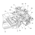
- FIG. 2 is a perspective view of the rear of the vehicle, focusing on the rear drive unit 20 of this embodiment.
- a pair of suspension members 80 extending in the vehicle's fore-and-aft direction are arranged on the left and right sides of the rear drive unit 20.
- the suspension members 80 support the inverter unit 21, drive motor 22, and reduction gear 23, which are integrally constructed.
- One end of the harness 35 is configured as a first connection portion 351 that is connected to the battery side connector 31 of the battery unit 30.
- the battery unit 30 has an upright portion 32 formed on the upper surface of its rear part, positioned to the left in the vehicle width direction.
- the battery side connector 31 is disposed on the rear end surface of the upright portion 32.
- the first connection portion 351 of the harness 35 connects to the battery side connector 31 toward the front of the vehicle.
- the other end of the harness 35 is configured as a second connection portion 355 that is connected to the inverter side connector 26 of the inverter unit 21.
- the inverter side connector 26 is disposed on the left side of the inverter unit 21.
- the second connection portion 355 of the harness 35 is connected to the inverter side connector 26 toward the right side in the vehicle width direction.
- the battery side connector 31 is configured to be located further to the left in the vehicle width direction than the inverter side connector 26.
- the harness 35 is connected to the battery side connector 31 located on the left side of the battery unit 30 and the inverter side connector 26 located on the left side of the rear drive unit 20.
- the harness 35 is configured to curve left and right between the first connection part 351 and the second connection part 355, i.e., in the space behind the battery unit 30 and to the side of the rear drive unit 20 in the vehicle width direction.
- the harness 35 is composed of a first extension portion 352 that curves to the right from the first connection portion 351 and extends in the vehicle width direction, a second extension portion 353 that curves rearward from the first extension portion 352 and extends rearward while passing above the suspension member 80, and a third extension portion 354 that curves in a U-shape from the second extension portion 353 and faces forward, then turns right and connects to the second connection portion 355.
- the harness 35 is routed while curving in the vehicle width direction between the first connection part 351 and the second connection part 355, so that the harness 35 has sufficient leeway to swing.
- the first extension 352 of the harness 35 is fixed to the upper surface of the battery unit 30 via the first bracket 41.
- the second extension 353 of the harness 35 is fixed to the upper surface of the suspension member 80 via the second bracket 42.
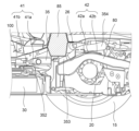
- Figure 3 is a cross-sectional view of the rear drive unit 20.
- a cross member 85 is disposed above and between the battery unit 30 and the rear drive unit 20.
- the cross member 85 is integral with the floor panel 100.
- the harness 35 is arranged in the second extension section 353 so as to pass under the cross member 85 from the front to the rear of the vehicle.
- the position (ground clearance) of the inverter side connector 26 of the rear drive unit 20 is configured to be higher than the position (ground clearance) of the battery side connector 31 of the battery unit 30.
- the harness 35 can be curved not only in the vehicle width direction, but also in the vertical direction.
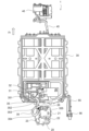
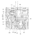
- the position in the vehicle width direction where the harness 35 passes through the cross member 85 is positioned outboard in the vehicle width direction of the inverter side connector 26 where the harness 35 is connected to the inverter unit 21 (indicated by T in FIG. 6).
- the harness 35 is prevented from being pinched by the cross member 85 or these structures, and damage to the harness 35 can be suppressed. Furthermore, because the harness 35 is not positioned above the cross member 85, the passenger compartment space above the cross member 85 is not sacrificed.
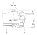
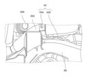
- FIG. 4 is an explanatory diagram of the vicinity of the first extension portion 352 to which the first bracket 41 of this embodiment is fixed
- FIG. 5 is an explanatory diagram of the vicinity of the second extension portion 353 to which the second bracket 42 is fixed.
- the first bracket 41 is composed of a support portion 41a that supports the first extension portion 352 of the harness 35, and a fixing portion 41b that is a plate-like member extending from the support portion 41a and fixed to the battery unit 30.
- the support portion 41a is an annular member made of resin or the like.
- the support portion 41a supports the first extension portion 352 by being fitted onto the outside of the first extension portion 352.
- the fixing portion 41b is a long plate-like member made of metal or resin. One end of the fixing portion 41b is fixed to the upper surface of the battery unit 30, and the other end of the fixing portion 41b is fixed to the support portion 41a.
- the second bracket 42 is made up of a support portion 42a that supports the second extension portion 353 of the harness 35, and a fixed portion 42b that is a plate-like member extending from the support portion 42a and fixed to the suspension member 80.
- the support portion 42a is an annular member made of resin or the like.
- the support portion 42a supports the second extension portion 353 by being fitted onto the outside of the second extension portion 353.
- the fixed portion 42b is a long plate-like member made of metal or resin. One end of the fixed portion 42b is fixed to the upper surface of the suspension member 80, and the other end of the fixed portion 42b is fixed to the support portion 42a.
- the harness 35 is fixed to the first bracket 41 and the second bracket 42 at the first extension portion 352 and the second extension portion 353, respectively, thereby preventing the harness 35 from swinging more than necessary while ensuring the swinging margin of the harness 35.
- the harness 35 is supported by the first bracket 41 and the second bracket 42 via the fixing parts 41b and 42b, which are long plate-shaped members, and these can elastically deform to cushion the swinging of the harness 35.
- the harness 35 can be curved not only in the vehicle width direction but also in the up and down direction between the first bracket 41 and the second bracket 42 to which the harness 35 is fixed.
- the position of the first bracket 41 in the vehicle width direction is located to the right of the position of the second bracket 42 in the vehicle width direction.
- FIG. 6 is a top view of the rear drive unit 20 and its surroundings in this embodiment
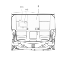
- FIG. 7 is a top view of the rear seat B and its surroundings in the vehicle cabin.
- the battery side connector 31 of the battery unit 30 is disposed on an upright portion 32 that stands on the upper surface of the rear of the battery unit 30.
- the space between the battery unit 30 and the rear drive unit 20 is not large, which creates a problem in that it is difficult to remove the harness 35 when performing maintenance on the battery unit 30 or the rear drive unit 20.
- a service hole 110 that can communicate from the inside of the vehicle compartment to the battery unit 30 is provided in the floor panel 100 located directly above the battery unit 30.
- the service hole 110 is configured as an opening that is connected from the top of the floor panel 100 to the standing portion 32 of the battery unit 30, directly above the standing portion 32 on which the battery side connector 31 is provided.
- the service hole 110 is fixed with a cover 111 by bolting.
- the service hole 110 is positioned so that it is located under the rear seat B inside the vehicle cabin.
- the vehicle 1 includes the rear drive unit 20 that drives the vehicle 1, and the battery unit 30 that supplies power to the rear drive unit 20 via the harness 35.
- the rear drive unit 20 is disposed rearward of the battery unit 30, and includes a drive motor 22 that drives the drive wheels 15, and an inverter unit 21 that converts the power of the battery unit 30 and supplies it to the drive motor 22.
- One end of the harness 35 is configured as a first connection portion 351 that is connected to the battery unit 30 at the rear of the battery unit 30 toward the front of the vehicle, and the other end is configured as a second connection portion 355 that is connected to the inverter unit 21 at the side of the inverter unit 21 toward the vehicle width direction.
- the harness 35 is arranged so as to curve at least in the vehicle width direction between the first connection portion 351 and the second connection portion 355.
- the harness 35 is connected toward the front of the vehicle at the rear of the battery unit 30, and is connected toward the width of the vehicle at the side of the rear drive unit 20.
- the harness 35 is routed so as to curve in the vehicle width direction, using the space behind the battery unit 30 and the side of the rear drive unit 20 in the vehicle width direction.
- the harness length of the harness 35 can be made to have some slack in the vehicle width direction between the battery unit 30 and the rear drive unit 20, so that even if the rear drive unit 20 sways, the stress applied to the harness 35 can be alleviated.
- the harness 35 has a first extension portion 352 that curves from the first connection portion 351 and extends in the vehicle width direction, a second extension portion 353 that curves from the first extension portion 352 and extends toward the rear of the vehicle, and a third extension portion 354 that curves from the second extension portion 353 and extends in the vehicle width direction and then reaches the second connection portion 355, and the first extension portion 352 is fixed to the battery unit 30 and the second extension portion 353 is fixed to the rear drive unit 20.
- the harness 35 is routed while being curved between the first connection part 351 and the second connection part 355, so that the curved parts of the harness 35 can have some room to swing.
- first extension 352 is fixed to the battery unit 30 via the first bracket 41
- second extension 353 is fixed to the rear drive unit 20 via the second bracket 42
- the fixed position of the first bracket 41 to the battery unit 30 and the fixed position of the second bracket 42 to the rear drive unit 20 differ in the vehicle width direction and the vehicle up-down direction.
- the harness 35 is routed between the first bracket 41 and the second bracket 42, curving not only in the width direction of the vehicle but also in the vertical direction, allowing the harness 35 to have some room to swing.
- the floor panel 100 of the vehicle 1 is disposed directly above the standing portion 32 of the battery unit 30, which has the battery side connector 31 to which the first connection portion 351 of the harness 35 is connected, and the rear seat B is fixed above the floor panel 100.
- the floor panel 100 has a service hole 110 below the rear seat B, which opens from the top of the floor panel 100 to be able to communicate with the standing portion 32.
- the service hole 110 for maintenance of the battery unit 30 and the rear drive unit 20 is provided below the rear seat B, preventing passengers in the vehicle 1 from accidentally touching the harness 35 and the battery side connector 31, which are high voltage parts.
- the vehicle 1 has a cross member 85 that crosses the vehicle width direction between the battery unit 30 and the rear drive unit 20, and the harness 35 is arranged so as to pass under the cross member 85 between the battery unit 30 and the rear drive unit 20, and the position where the harness 35 passes under the cross member 85 is arranged outside the second connection part 355 in the vehicle width direction.
- a configuration including a front drive unit 40 and a rear drive unit 20 is shown, but this is not limited to this. It can also be applied to a vehicle that does not include a front drive unit 40 and runs on only the rear drive unit 20. Furthermore, in a vehicle that does not include a rear drive unit 20 and only includes a front drive unit 40, the front harness 45 connected to the front drive unit 40 and the battery unit 30 may be configured to be curved and routed like the harness 35 described above.
Landscapes
- Engineering & Computer Science (AREA)
- Mechanical Engineering (AREA)
- Transportation (AREA)
- Life Sciences & Earth Sciences (AREA)
- Sustainable Development (AREA)
- Sustainable Energy (AREA)
- Power Engineering (AREA)
- Chemical & Material Sciences (AREA)
- Combustion & Propulsion (AREA)
- Arrangement Or Mounting Of Propulsion Units For Vehicles (AREA)
Priority Applications (4)
| Application Number | Priority Date | Filing Date | Title |
|---|---|---|---|
| JP2025527002A JPWO2024257272A1 (cg-RX-API-DMAC7.html) | 2023-06-14 | 2023-06-14 | |
| PCT/JP2023/022104 WO2024257272A1 (ja) | 2023-06-14 | 2023-06-14 | ハーネスの取付構造 |
| EP23940943.6A EP4729365A4 (en) | 2023-06-14 | 2023-06-14 | HARNESS FIXING STRUCTURE |
| CN202380099244.7A CN121311388A (zh) | 2023-06-14 | 2023-06-14 | 线束的安装结构 |
Applications Claiming Priority (1)
| Application Number | Priority Date | Filing Date | Title |
|---|---|---|---|
| PCT/JP2023/022104 WO2024257272A1 (ja) | 2023-06-14 | 2023-06-14 | ハーネスの取付構造 |
Publications (1)
| Publication Number | Publication Date |
|---|---|
| WO2024257272A1 true WO2024257272A1 (ja) | 2024-12-19 |
Family
ID=93851558
Family Applications (1)
| Application Number | Title | Priority Date | Filing Date |
|---|---|---|---|
| PCT/JP2023/022104 Ceased WO2024257272A1 (ja) | 2023-06-14 | 2023-06-14 | ハーネスの取付構造 |
Country Status (4)
| Country | Link |
|---|---|
| EP (1) | EP4729365A4 (cg-RX-API-DMAC7.html) |
| JP (1) | JPWO2024257272A1 (cg-RX-API-DMAC7.html) |
| CN (1) | CN121311388A (cg-RX-API-DMAC7.html) |
| WO (1) | WO2024257272A1 (cg-RX-API-DMAC7.html) |
Citations (6)
| Publication number | Priority date | Publication date | Assignee | Title |
|---|---|---|---|---|
| JP2012096715A (ja) * | 2010-11-04 | 2012-05-24 | Suzuki Motor Corp | バッテリユニットの冷却用ダクト構造 |
| JP2013112225A (ja) * | 2011-11-29 | 2013-06-10 | Toyota Motor Corp | 車両用電池搭載構造 |
| JP2016159816A (ja) | 2015-03-03 | 2016-09-05 | 日産自動車株式会社 | 電動車両のハーネス接続構造 |
| JP2019032974A (ja) * | 2017-08-07 | 2019-02-28 | 矢崎総業株式会社 | ワイヤハーネス |
| JP2021011262A (ja) * | 2020-10-09 | 2021-02-04 | 本田技研工業株式会社 | 車両 |
| WO2021166337A1 (ja) * | 2020-02-19 | 2021-08-26 | 三菱自動車工業株式会社 | ハイブリッド車両における電力線の配索構造 |
Family Cites Families (2)
| Publication number | Priority date | Publication date | Assignee | Title |
|---|---|---|---|---|
| WO2021111809A1 (ja) * | 2019-12-06 | 2021-06-10 | 三菱自動車工業株式会社 | 車両の駆動ユニット |
| JP7563269B2 (ja) * | 2021-03-26 | 2024-10-08 | マツダ株式会社 | 電動車両の下部構造 |
-
2023
- 2023-06-14 JP JP2025527002A patent/JPWO2024257272A1/ja active Pending
- 2023-06-14 CN CN202380099244.7A patent/CN121311388A/zh active Pending
- 2023-06-14 EP EP23940943.6A patent/EP4729365A4/en not_active Withdrawn
- 2023-06-14 WO PCT/JP2023/022104 patent/WO2024257272A1/ja not_active Ceased
Patent Citations (6)
| Publication number | Priority date | Publication date | Assignee | Title |
|---|---|---|---|---|
| JP2012096715A (ja) * | 2010-11-04 | 2012-05-24 | Suzuki Motor Corp | バッテリユニットの冷却用ダクト構造 |
| JP2013112225A (ja) * | 2011-11-29 | 2013-06-10 | Toyota Motor Corp | 車両用電池搭載構造 |
| JP2016159816A (ja) | 2015-03-03 | 2016-09-05 | 日産自動車株式会社 | 電動車両のハーネス接続構造 |
| JP2019032974A (ja) * | 2017-08-07 | 2019-02-28 | 矢崎総業株式会社 | ワイヤハーネス |
| WO2021166337A1 (ja) * | 2020-02-19 | 2021-08-26 | 三菱自動車工業株式会社 | ハイブリッド車両における電力線の配索構造 |
| JP2021011262A (ja) * | 2020-10-09 | 2021-02-04 | 本田技研工業株式会社 | 車両 |
Non-Patent Citations (1)
| Title |
|---|
| See also references of EP4729365A4 |
Also Published As
| Publication number | Publication date |
|---|---|
| EP4729365A1 (en) | 2026-04-22 |
| JPWO2024257272A1 (cg-RX-API-DMAC7.html) | 2024-12-19 |
| CN121311388A (zh) | 2026-01-09 |
| EP4729365A4 (en) | 2026-07-29 |
Similar Documents
| Publication | Publication Date | Title |
|---|---|---|
| US11492044B2 (en) | Vehicle front structure | |
| US9394004B2 (en) | Electric automobile | |
| JP5589772B2 (ja) | 電動車両の電装部品搭載構造 | |
| CN102673492B (zh) | 车辆中的高压电缆的布线结构 | |
| JP2020124966A (ja) | 車両 | |
| JP5691559B2 (ja) | 車両用電気接続箱の搭載構造 | |
| JP2017185913A (ja) | 走行用モータを備えている自動車 | |
| WO2021145056A1 (ja) | 電動車両における電源ユニットの配置構造 | |
| JP6688851B2 (ja) | 車両 | |
| JP7662063B2 (ja) | ワイヤハーネスの取付構造 | |
| CN111661166B (zh) | 车辆前部结构 | |
| CN107471990B (zh) | 电池包的保护结构 | |
| JP2021030833A (ja) | 車両前部構造 | |
| JP2023136720A (ja) | 電動車両の駆動装置 | |
| JP4479299B2 (ja) | 車体下部構造 | |
| JP5929749B2 (ja) | 車載機器の搭載構造 | |
| US11912117B2 (en) | Vehicle | |
| JP7487660B2 (ja) | 車載機器の取り付け構造 | |
| EP4729365A1 (en) | Harness attachment structure | |
| JP2023128747A (ja) | 電動車 | |
| JP7272133B2 (ja) | 車両のケーブル取付構造 | |
| JP7588166B2 (ja) | 車両用駆動装置 | |
| JPWO2024257272A5 (cg-RX-API-DMAC7.html) | ||
| JP2026082236A (ja) | 駆動装置の支持構造 | |
| JP6950606B2 (ja) | 走行用モータを制御する電力制御器の支持構造 |
Legal Events
| Date | Code | Title | Description |
|---|---|---|---|
| 121 | Ep: the epo has been informed by wipo that ep was designated in this application |
Ref document number: 23940943 Country of ref document: EP Kind code of ref document: A1 |
|
| ENP | Entry into the national phase |
Ref document number: 2025527002 Country of ref document: JP Kind code of ref document: A |
|
| WWE | Wipo information: entry into national phase |
Ref document number: 2023940943 Country of ref document: EP |
|
| NENP | Non-entry into the national phase |
Ref country code: DE |
|
| ENP | Entry into the national phase |
Ref document number: 2023940943 Country of ref document: EP Effective date: 20260114 |
|
| ENP | Entry into the national phase |
Ref document number: 2023940943 Country of ref document: EP Effective date: 20260114 |
|
| ENP | Entry into the national phase |
Ref document number: 2023940943 Country of ref document: EP Effective date: 20260114 |
|
| ENP | Entry into the national phase |
Ref document number: 2023940943 Country of ref document: EP Effective date: 20260114 |
|
| WWP | Wipo information: published in national office |
Ref document number: 2023940943 Country of ref document: EP |