WO2024257250A1 - 室内機、および空気調和機 - Google Patents
室内機、および空気調和機 Download PDFInfo
- Publication number
- WO2024257250A1 WO2024257250A1 PCT/JP2023/022025 JP2023022025W WO2024257250A1 WO 2024257250 A1 WO2024257250 A1 WO 2024257250A1 JP 2023022025 W JP2023022025 W JP 2023022025W WO 2024257250 A1 WO2024257250 A1 WO 2024257250A1
- Authority
- WO
- WIPO (PCT)
- Prior art keywords
- wall portion
- refrigerant
- heat exchanger
- drain pan
- sensor unit
- Prior art date
- Legal status (The legal status is an assumption and is not a legal conclusion. Google has not performed a legal analysis and makes no representation as to the accuracy of the status listed.)
- Ceased
Links
Images



Classifications
-
- F—MECHANICAL ENGINEERING; LIGHTING; HEATING; WEAPONS; BLASTING
- F24—HEATING; RANGES; VENTILATING
- F24F—AIR-CONDITIONING; AIR-HUMIDIFICATION; VENTILATION; USE OF AIR CURRENTS FOR SCREENING
- F24F11/00—Control or safety arrangements
- F24F11/89—Arrangement or mounting of control or safety devices
-
- F—MECHANICAL ENGINEERING; LIGHTING; HEATING; WEAPONS; BLASTING
- F24—HEATING; RANGES; VENTILATING
- F24F—AIR-CONDITIONING; AIR-HUMIDIFICATION; VENTILATION; USE OF AIR CURRENTS FOR SCREENING
- F24F2130/00—Control inputs relating to environmental factors not covered by group F24F2110/00
- F24F2130/20—Sunlight
Definitions
- This disclosure relates to indoor units and air conditioners.
- Patent Document 1 discloses an indoor unit in which a drain pan is placed below the heat exchanger and a refrigerant sensor is placed near the drain pan, allowing the refrigerant sensor to detect refrigerant gas that leaks from the heat exchanger and runs down the drain pan.
- the refrigerant sensor is located near the drain pan, so if condensation water collected in the drain pan were to leak or splash out due to an unforeseen event, the condensation water could get on the refrigerant sensor and affect the detection accuracy of the refrigerant sensor.
- one of the objectives of this disclosure is to provide an indoor unit and an air conditioner that can prevent condensation from affecting the detection accuracy of the refrigerant sensor.
- FIG. 1 is a schematic diagram showing a schematic configuration of an air conditioner according to an embodiment
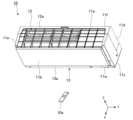
- FIG. 2 is a perspective view of the indoor unit according to the embodiment.
- FIG. 2 is a front view of the indoor unit according to the embodiment.
- FIG. 2 is a perspective view of a drain pan according to an embodiment.
- FIG. 2 is a side view of a control unit and a refrigerant sensor unit according to the embodiment.
- FIG. 2 is an exploded perspective view of a control unit and a refrigerant sensor unit according to the embodiment.
- FIG. 2 is a perspective view of the refrigerant sensor unit according to the embodiment.
- FIG. 2 is an exploded perspective view of the refrigerant sensor unit according to the embodiment.
- 2 is a perspective view of a housing main body of the refrigerant sensor unit according to the embodiment.
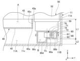
- FIG. FIG. 4 is a schematic diagram illustrating an area X in FIG. 3 .
- the drawings also show the X-axis, Y-axis, and Z-axis as appropriate.
- the X-axis shows one of the horizontal directions.
- the Y-axis shows the other of the horizontal directions.
- the Z-axis shows the vertical direction.
- the horizontal direction along the X-axis is called the "front-rear direction X”
- the horizontal direction along the Y-axis is called the "left-right direction Y”
- the vertical direction along the Z-axis is called the "vertical direction Z”.
- the front-rear direction X, the left-right direction Y, and the vertical direction Z are mutually perpendicular directions.
- the side in the vertical direction Z toward which the Z-axis arrow points (+Z side) is defined as the upper side
- the opposite side of the vertical direction Z toward which the Z-axis arrow points (-Z) is defined as the lower side.
- the left-right direction Y and the front-rear direction X are names simply used to describe the relative positional relationship of each part, and the actual positional relationship may be a positional relationship other than the positional relationship indicated by these names.
- the left-right direction Y corresponds to the "first direction”
- the right (+Y) corresponds to the "first side”
- the left corresponds to the "second side”.
- the front-rear direction X corresponds to the "second direction”
- the front (+X) corresponds to the "third side”
- the rear corresponds to the "fourth side”.
- Fig. 1 is a schematic diagram showing a general configuration of an air conditioner 100 in the present embodiment.
- the air conditioner 100 includes an indoor unit 10, an outdoor unit 20, and a refrigerant circuit 30.
- the indoor unit 10 is disposed indoors.
- the outdoor unit 20 is disposed outdoors.
- the indoor unit 10 and the outdoor unit 20 are connected to each other by the refrigerant circuit 30 through which refrigerant 33 circulates.
- the indoor unit 10 and the outdoor unit 20 are heat exchange units that exchange heat with air.
- the air conditioner 100 can adjust the temperature of the air in the room by exchanging heat between the refrigerant 33 flowing in the refrigerant circuit 30 and the air in the room in which the indoor unit 10 is located.
- the refrigerant 33 include fluorine-based refrigerants with low Global Warming Potential (GWP) or hydrocarbon-based refrigerants.
- GWP Global Warming Potential
- the refrigerant 33 include a single refrigerant selected from R1234yf, R1234ze, R32, and R290, or a mixture of two or more of these, or a mixture of any of these with another refrigerant.
- Examples of the refrigerant 33 include a mixed refrigerant containing R1132(E), or a mixed refrigerant containing R1123.
- refrigerant 33 examples include mixed refrigerants of R516A, R445A, R444A, R454C, R444B, R454A, R455A, R457A, R459B, R452B, R454B, R447B, R447A, R446A, and R459A.
- the outdoor unit 20 has a compressor 21, an outdoor heat exchanger 23, a flow control valve 24, an outdoor unit blower 25, and a four-way valve 22.
- the compressor 21, the outdoor heat exchanger 23, the flow control valve 24, and the four-way valve 22 are connected by a refrigerant circuit 30.
- the four-way valve 22 is disposed in a portion of the refrigerant circuit 30 that is connected to the discharge side of the compressor 21.
- the four-way valve 22 can reverse the direction of the refrigerant 33 flowing through the refrigerant circuit 30 by switching a portion of the path of the refrigerant circuit 30.
- the path connected by the four-way valve 22 is the path shown by the solid line on the four-way valve 22 in FIG. 1
- the refrigerant 33 flows through the refrigerant circuit 30 in the direction shown by the solid arrow in FIG. 1.
- the path connected by the four-way valve 22 is the path shown by the dashed line on the four-way valve 22 in FIG. 1
- the refrigerant 33 flows through the refrigerant circuit 30 in the direction shown by the dashed arrow in FIG. 1.
- the indoor unit 10 has a blower 15 and a heat exchanger 14 arranged around the blower 15.
- the indoor unit 10 is capable of cooling operation to cool the air in the room in which the indoor unit 10 is located, and heating operation to warm the air in the room in which the indoor unit 10 is located.
- the refrigerant 33 flowing through the refrigerant circuit 30 flows in the direction shown by the solid arrow in Figure 1.
- the refrigerant 33 flowing through the refrigerant circuit 30 circulates through the compressor 21, the outdoor heat exchanger 23 of the outdoor unit 20, the flow control valve 24, and the heat exchanger 14 of the indoor unit 10, in that order, before returning to the compressor 21.
- the outdoor heat exchanger 23 in the outdoor unit 20 functions as a condenser
- the heat exchanger 14 in the indoor unit 10 functions as an evaporator.
- the refrigerant 33 flowing in the refrigerant circuit 30 flows in the direction shown by the dashed line in Figure 1.
- the refrigerant 33 flowing in the refrigerant circuit 30 circulates through the compressor 21, the heat exchanger 14 of the indoor unit 10, the flow control valve 24, and the outdoor heat exchanger 23 of the outdoor unit 20, in that order, before returning to the compressor 21.
- the outdoor heat exchanger 23 in the outdoor unit 20 functions as an evaporator
- the heat exchanger 14 in the indoor unit 10 functions as a condenser.
- FIG. 2 is a perspective view of the indoor unit 10 of this embodiment.
- the indoor unit 10 of this embodiment is a wall-mounted indoor unit that is fixed to an upper region of a wall surface inside a room.
- a remote controller 10a is attached to the indoor unit 10.
- the remote controller 10a transmits radio waves such as infrared rays toward the indoor unit 10 when operated by a resident in the room. This allows the resident to remotely control the indoor unit 10 by operating the remote controller 10a.
- FIG. 3 is a front view of the indoor unit 10 with the front panel 11b removed.
- the indoor unit 10 of this embodiment includes a drain pan 40, a control unit 50, and a refrigerant sensor unit 60 in addition to the housing 11, heat exchanger 14, and blower 15 described above.
- the housing 11 houses the heat exchanger 14, the blower 15, the drain pan 40, the control unit 50, and the refrigerant sensor unit 60.
- the housing 11 of this embodiment is a substantially rectangular box shape that is long in the left-right direction Y.
- the housing 11 has a top panel 11a, a front panel 11b, a bottom panel 11c, a first side panel (side panel) 11d, a second side panel 11e, and a back panel 11f.
- the top panel 11a covers the internal space of the housing 11 from above.
- the front panel 11b covers the internal space of the housing 11 from the front (+X).
- the bottom panel 11c covers the internal space of the housing 11 from below.
- the first side panel 11d covers the internal space of the housing 11 from the right (+Y).
- the second side panel 11e covers the internal space of the housing 11 from the left (-Y).
- the back panel 11f covers the internal space of the housing 11 from the rear (-X).
- the housing 11 is provided with an intake port 12 and an exhaust port 13.
- the intake port 12 is provided on the top panel 11a.
- the intake port 12 opens upward and extends in the left-right direction Y.
- a filter 12a that removes dust from the intake air is disposed in the intake port 12.
- the exhaust port 13 is provided at the lower end of the front panel 11b.
- the exhaust port 13 opens forward (+X) and downward, and extends in the left-right direction Y.
- the exhaust port 13 is provided with an air direction vane 13a that adjusts the direction of the air blown out.
- a fan chamber 11A and a machine chamber 11B are provided in the internal space of the housing 11.
- the fan chamber 11A and the machine chamber 11B are arranged side by side in the left-right direction Y.
- the fan chamber 11A is equipped with a heat exchanger 14, a blower 15, and a drain pan 40.
- the fan chamber 11A is also connected to the intake port 12 and the exhaust port 13.
- the machine chamber 11B is arranged to the right (+Y) of the fan chamber 11A.
- the control unit 50 and the refrigerant sensor unit 60 are arranged in the machine chamber 11B.
- the blower 15 of this embodiment is a cross-flow fan.
- the blower 15 has an impeller 15a extending in the left-right direction Y and a drive motor 15b disposed to the right (+Y) of the impeller 15a.
- the impeller 15a is substantially cylindrical and has a plurality of blades (not shown) arranged in the circumferential direction.
- the impeller 15a and the drive motor 15b rotate the impeller 15a around a rotation axis extending in the left-right direction Y.
- the heat exchanger 14 is located in front (+X) and above (+Z) the blower 15.
- a refrigerant flows inside the heat exchanger 14.
- the heat exchanger 14 exchanges heat between the air in the fan chamber 11A and the refrigerant. In this way, the heat exchanger 14 cools or heats the air sucked into the blower 15.
- the drain pan 40 is disposed below the heat exchanger 14 and above the bottom panel 11c of the housing 11.
- the drain pan 40 extends in the left-right direction Y.
- the drain pan 40 receives condensed water that condenses and drips from the surface of the heat exchanger 14 from below.
- the condensed water received by the drain pan 40 is discharged to the outside via a drain hose (not shown).
- the drain pan 40 receives vaporized refrigerant (hereinafter referred to as refrigerant gas) from below in the event of refrigerant leakage from the heat exchanger 14.
- refrigerant gas vaporized refrigerant
- FIG 4 is an oblique view of the drain pan 40.
- the drain pan 40 has a drain pan main body 41 and a stabilizer portion 45.
- the drain pan 40 of this embodiment is a resin molded product in which the drain pan main body 41 and the stabilizer portion 45 are integrated.
- the drain pan main body 41 and the stabilizer portion 45 may be composed of separate members.
- the drain pan 40 receives condensation water and refrigerant gas in the drain pan main body 41, and regulates the air flow in the fan chamber 11A in the stabilizer portion 45.
- the drain pan main body 41 and the stabilizer portion 45 both extend in the left-right direction Y.
- the stabilizer portion 45 is positioned rearward (-X) of the drain pan main body 41.
- the stabilizer portion 45 has a tongue portion 46 that protrudes rearward (-X).
- the tongue portion 46 extends in the left-right direction Y.
- the tongue portion 46 faces the outer peripheral surface of the impeller 15a (see Figure 3) via a gap.
- the drain pan main body 41 has a storage space A that opens upward.
- the drain pan main body 41 is capable of storing condensed water in the storage space A.
- the drain pan main body 41 has a bottom 42 and a peripheral wall 43.
- the bottom 42 is plate-shaped and extends along a plane perpendicular to the vertical direction Z.
- the bottom 42 extends in the left-right direction Y.
- the bottom 42 faces the heat exchanger 14 in the vertical direction Z.
- the bottom 42 is located below the storage space A. Condensed water in the storage space A accumulates above the upper surface of the bottom 42.
- a drain hole (not shown) that connects to a drain hose is opened in the bottom 42.
- the peripheral wall portion 43 extends upward from the outer edge of the bottom portion 42. When viewed from above, the peripheral wall portion 43 surrounds the storage space A from the front, rear, left and right.
- the peripheral wall portion 43 has a front wall portion 43a, a rear wall portion 43b, a first side wall portion (side wall portion) 43c and a second side wall portion 43d.
- the front wall portion 43a is located in front of the storage space A (+X).
- the rear wall portion 43b is located in the rear of the storage space A (-X).
- the first side wall portion 43c is located to the right of the storage space A (+Y).
- the second side wall portion 43d is located to the left of the storage space A (-Y).
- the heights of the upper ends of each portion of the peripheral wall portion 43 are approximately the same. That is, the heights of the upper ends of the front wall portion 43a, the rear wall portion 43b, the first side wall portion 43c and the second side wall portion 43d are the same. However, the heights of the upper ends of the front wall portion 43a, the rear wall portion 43b, the first side wall portion 43c, and the second side wall portion 43d may be different from each other. In this case, it is preferable that the upper end of the first side wall portion 43c is located lower than the upper ends of the front wall portion 43a, the rear wall portion 43b, and the second side wall portion 43d.
- the front wall portion 43a and the rear wall portion 43b face each other in the front-to-rear direction X.
- the front wall portion 43a slopes in the forward (+X) direction as it extends upward.
- the rear wall portion 43b slopes in the backward (-X) direction as it extends upward.
- the front wall portion 43a and the rear wall portion 43b move away from each other in the front-to-rear direction X as they extend upward.
- the front wall portion 43a and the rear wall portion 43b ensure a wide opening of the storage space A in the front-to-rear direction X, and can receive condensation water over a wide range in the front-to-rear direction X and direct the condensation water to the upper surface of the bottom portion 42.
- the first side wall portion 43c and the second side wall portion 43d face each other in the left-right direction Y.
- the first side wall portion 43c and the second side wall portion 43d each extend along a plane perpendicular to the left-right direction Y.
- the first side wall portion 43c is located on the rightmost side (+Y) of the peripheral wall portion 43.
- the machine room 11B is provided between the first side wall portion 43c located on the rightmost side (+Y) of the peripheral wall portion 43 and the first side panel 11d of the housing 11.
- FIG. 5 is a side view of the control unit 50 and the refrigerant sensor unit 60.
- FIG. 6 is an exploded perspective view of the control unit 50 and the refrigerant sensor unit 60.
- the control unit 50 has an electrical equipment box 52, a control board 51, a terminal block 54, a cable 53, a cable guide 59, and a receiving device 58. That is, the indoor unit 10 has the electrical equipment box 52, the control board 51, the terminal block 54, the cable 53, the cable guide 59, and the receiving device 58.
- the control board 51 controls the components necessary for the cooling and heating operation of the air conditioner 100.
- the control board 51 controls each part of the indoor unit 10.
- the control board 51 controls the blower 15, the heat exchanger 14, etc.
- control board 51 can communicate with the control unit (not shown) of the outdoor unit 20 via the terminal block 54.
- a cable 53 extending from the outdoor unit 20 is connected to the terminal block 54.
- the terminal block 54 functions as a repeater for communication between the control board 51 of the indoor unit 10 and the control unit of the outdoor unit 20.
- the control board 51 has a number of electronic components mounted on its surface. These electronic components include, for example, transistors and a microcomputer. Note that in this embodiment, the control unit 50 has only one control board 51, but the control unit 50 may have a number of control boards 51. In this case, the multiple control boards 51 are connected to each other.
- the multiple cables 53 are connected to the control board 51 or the terminal block 54. Some of the multiple cables 53 connect each part of the indoor unit 10 to the control board 51. In addition, some of the multiple cables 53 connect the terminal block 54 to the control unit (not shown) of the outdoor unit 20.
- the electrical equipment box 52 is a box that houses the control board 51 or the terminal block 54 inside.
- An opening is provided in the lower part 52a of the electrical equipment box 52, which opens the internal space of the electrical equipment box 52 downward.
- a cable guide 59 that covers the opening is fixed to the lower part 52a of the electrical equipment box 52.
- the cable guide 59 has a hollow portion 59A inside that communicates with an opening provided in the lower portion 52a of the electrical equipment box.
- the cable guide 59 also has a cable insertion portion 59a that opens the hollow portion 59A rearward (-X).
- the multiple cables 53 are inserted from the cable insertion portion 59a and pass through the hollow portion 59A of the cable guide 59, and are guided from the lower portion 52a of the electrical equipment box 52 to the internal space of the electrical equipment box 52. In other words, the cable guide 59 guides the multiple cables 53 into the interior of the electrical equipment box 52.
- the cable guide 59 has a sensor fixing portion 59d and a receiver fixing portion 59b.
- the refrigerant sensor unit 60 is fixed to the sensor fixing portion 59d.
- the receiver 58 is fixed to the receiver fixing portion 59b.
- the sensor fixing portion 59d and the receiver fixing portion 59b are arranged side by side in the front-rear direction X.
- the sensor fixing portion 59d is located rearward (-X) of the receiver fixing portion 59b.
- the sensor fixing portion 59d has a sensor support surface 59f, a first boss 59e, and a locking portion 59g.
- the sensor support surface 59f is disposed between the first boss 59e and the locking portion 59g in the front-rear direction X.
- the sensor support surface 59f is a flat surface perpendicular to the vertical direction Z.
- the first boss 59e is located in front of the sensor support surface 59f (+X).
- the first boss 59e is cylindrical and protrudes downward.
- a screw hole 59h that opens downward is provided on the lower end surface of the first boss 59e.
- a fixing screw 59j that screws and fixes the refrigerant sensor unit 60 is inserted into the screw hole 59h.
- the receiving device 58 has an antenna unit (not shown), a receiving board (not shown) on which the antenna unit is mounted, a receiving device case 58a that houses them, and a display unit 58b provided on the front of the receiving device case 58a.
- the receiving device 58 receives radio waves from the remote controller 10a transmitted from the front (+X) of the indoor unit 10. For this reason, the receiving device 58 is arranged inside the housing 11 so as to face the front (+X). Furthermore, a window 11w is provided in the part of the front panel 11b of the housing 11 located in front (+X) of the receiving device 58 to prevent damage to the radio waves reaching the receiving device 58.
- the display unit 58b is, for example, a light-emitting diode, and displays the driving status of the indoor unit 10 by emitting light.
- the display unit 58b is arranged so as to be visible from the indoor side through the window 11w.
- the refrigerant sensor unit 60 is positioned to the right (+Y) of the drain pan 40.
- the refrigerant gas leaks from the heat exchanger 14
- the refrigerant gas is heavier than air and flows downward to accumulate in the storage space A of the drain pan 40.
- the refrigerant gas then flows over the first side wall portion 43c of the drain pan 40 into the machine chamber 11B, and accumulates above the bottom panel 11c, which is located below the drain pan 40.
- the refrigerant sensor unit 60 detects the refrigerant gas accumulating above the bottom panel 11c and transmits the detection result to the control unit 50.
- a component overlaps with another component in one direction means that the range of positions of the component in one direction overlaps with the range of positions of the other component in one direction. Therefore, “the refrigerant sensor unit 60 overlaps with the drain pan 40 in the front-to-rear direction X” means that the range of the refrigerant sensor unit 60 in the front-to-rear direction X from the front end to the rear end at least partially overlaps with the range of the drain pan 40 in the front-to-rear direction X from the front end to the rear end.
- FIG. 7 is a perspective view of the refrigerant sensor unit 60.
- FIG. 8 is an exploded perspective view of the refrigerant sensor unit 60.
- the refrigerant sensor unit 60 has a refrigerant sensor 70 and a housing 80.
- the refrigerant sensor 70 is housed inside the housing 80.
- the refrigerant sensor 70 has a sensor board 73, a sensor element 71, and an element case 72.
- the sensor board 73 is fixed to the inner surface of the housing 80.
- the sensor board 73 extends along a plane perpendicular to the front-rear direction X.
- the sensor board 73 has a mounting surface 73a on which multiple elements are mounted. In this embodiment, the mounting surface 73a faces forward (+X).
- the sensor element 71 detects vaporized refrigerant gas.
- the sensor element 71 is mounted on the mounting surface 73a of the sensor board 73.
- the sensor element 71 is surrounded by the element case 72.
- the element case 72 is cylindrical and extends forward (+X) from the mounting surface 73a.
- the element case 72 has a base end 72a fixed to the mounting surface 73a and a tip end 72b which is the end opposite the base end 72a.
- the base end 72a of the element case 72 is fixed to the mounting surface 73a without any gaps by adhesive or the like.
- the tip end 72b of the element case 72 is provided with a case opening 72h which introduces refrigerant gas into the inside of the element case 72.
- the refrigerant gas flows into the inside of the element case 72 from the case opening 72h.
- an accommodation space B is provided inside the housing 80 to accommodate the refrigerant sensor 70.
- a gas inlet 80a is provided on the bottom surface of the housing 80. The gas inlet 80a takes in the refrigerant gas leaking from the heat exchanger 14 into the accommodation space B.
- the housing 80 has a lid 81, a housing body 82, and a sealing member 89.
- the lid 81 and the housing body 82 are assembled together to define the storage space B.
- the direction in which the lid 81 and the housing body 82 are assembled is referred to as the assembly direction D1.
- the assembly direction D1 is the vertical direction Z.
- the housing body 82 is located below the lid 81.
- FIG 9 is a perspective view of the housing body 82.
- the housing body 82 has a second box-shaped portion 82b, a second flange portion 82c, a fixing plate portion 82e, a locking hook 84, and a pair of arms 82d.
- the second box-shaped portion 82b opens at a second opening 82a.
- the second opening 82a faces the lid body 81 side in the assembly direction D1.
- the second box-shaped portion 82b is provided with a gas inlet 80a.
- a groove 82m is provided on an inner surface 82k of the second box-shaped portion 82b that extends along a plane perpendicular to the front-rear direction X.
- the groove 82m is connected to the gas inlet 80a.
- the groove 82m extends upward (+Z) from the gas inlet 80a.
- the groove 82m faces the case opening 72h of the element case 72 shown in FIG. 8 in the front-rear direction X.
- the refrigerant gas that has entered the inside of the housing 80 from the gas inlet 80a is smoothly guided through the inside of the groove 82m to the case opening 72h.
- the refrigerant gas that has entered the inside of the housing 80 can be smoothly guided to the inside of the element case 72, and the refrigerant gas can be immediately detected by the sensor element 71 in the element case 72.
- the detection responsiveness of the refrigerant sensor unit 60 can be improved.
- the second box-shaped portion 82b is formed of a plurality of walls configured in a box shape.
- the plurality of walls of the second box-shaped portion 82b include a first wall portion 80b, a second wall portion 80d, a third wall portion 80e, and a lower end wall portion 80c.
- the first wall portion 80b and the lower end wall portion 80c extend along a plane perpendicular to the vertical direction Z.
- the lower end wall portion 80c is located at the lowest of the plurality of walls that constitute the second box-shaped portion 82b.
- the downward surface of the lower end wall portion 80c constitutes the lower end surface of the housing 80.
- the first wall portion 80b is located above the first wall portion 80b.
- a gas inlet 80a opens in the first wall portion 80b.
- the second wall portion 80d and the third wall portion 80e connect the first wall portion 80b and the lower end wall portion 80c.
- the second wall portion 80d extends downward from the left (-Y) end of the first wall portion 80b.
- the second wall portion 80d extends along a plane perpendicular to the left-right direction Y.
- the second wall portion 80d of this embodiment has a step portion, the second wall portion 80d may be a uniform flat plate.
- the second wall portion 80d of this embodiment overlaps the gas inlet 80a in the front-rear direction X.
- the range of the second wall portion 80d from the front end to the rear end in the front-rear direction X at least partially overlaps with the range of the gas inlet 80a from the front end to the rear end in the front-rear direction X.
- the third wall portion 80e extends downward from the rear (-X) end of the first wall portion 80b.
- the third wall portion 80e extends along a plane perpendicular to the front-rear direction X.
- the first opening 81a and the second opening 82a overlap each other. This connects the internal space of the first box-shaped portion 81b and the internal space of the second box-shaped portion 82b to form the storage space B.
- the second flange portion 82c is connected to the outer edge of the second opening 82a.
- the second flange portion 82c protrudes in a direction perpendicular to the assembly direction D1 and away from the second opening 82a.
- the second flange portion 82c surrounds the second opening 82a when viewed from the assembly direction D1.
- the pair of arms 82d are connected to the second flange portion 82c.
- the pair of arms 82d are arranged on both sides of the second opening 82a in the left-right direction Y.
- Each arm 82d has a pair of connecting pieces 82i extending toward the lid body 81 in the assembly direction D1, and a locking piece 82j connecting the tips of the pair of connecting pieces 82i.
- the tip surface of the protrusion 81d is inclined, when the housing body 82 is assembled to the lid body 81, the locking piece 82j slides along the tip surface of the protrusion 81d, and the pair of arms 82d are elastically deformed. This allows the operator to easily hook the locking piece 82j onto the protrusion 81d.
- the fixing plate portion 82e is a plate extending along a plane perpendicular to the vertical direction Z.
- the fixing plate portion 82e is provided on the outer edge of the second flange portion 82c.
- the fixing plate portion 82e protrudes in a direction perpendicular to the assembly direction D1 and away from the second opening 82a. In this embodiment, the fixing plate portion 82e protrudes forward (+X).
- the fixing plate portion 82e is provided with a screw insertion hole 82h that penetrates the fixing plate portion 82e in the thickness direction.
- the fixing screw 59j is inserted into the screw insertion hole 82h.
- the fixing screw 59j is also screwed into the screw hole 59h of the cable guide 59.
- the fixing plate portion 82e is fixed to the cable guide 59.
- the locking hook 84 is provided on the outer edge of the second flange portion 82c.
- the locking hook 84 protrudes in a direction perpendicular to the assembly direction D1 and away from the second opening 82a.
- the locking hook 84 protrudes rearward (-X).
- the locking hook 84 and the fixing plate portion 82e are located on opposite sides of the second opening 82a in the front-rear direction X, and protrude on opposite sides in the front-rear direction X.
- the locking hook 84 has a first protrusion 84a, a second protrusion 84b, and a locking plate portion 84c that are arranged in a crank shape.
- the first protrusion 84a extends rearward (-X) from the second flange portion 82c.
- the second protrusion 84b extends upward (+Z) from the tip of the first protrusion 84a.
- the locking plate portion 84c extends rearward (-X) from the upper end of the second protrusion 84b.
- the locking plate portion 84c is a plate-like member perpendicular to the assembly direction D1.
- the locking plate portion 84c is provided with a locking surface 84f facing downward.
- the locking surface 84f extends along a plane perpendicular to the vertical direction Z. As shown in FIG.
- the locking hook 84 is inserted into the notch 59k of the cable guide 59.
- the locking surface 84f of the locking hook 84 faces and contacts the upper surface of the locking portion 59g where the notch 59k is provided. As a result, the locking hook 84 is locked to the locking portion 59g.
- the sealing member 89 is sandwiched between the first flange portion 81c of the housing 80 and the second flange portion 82c of the housing main body 82.
- the sealing member 89 is composed of a sponge-like elastic member.
- the sealing member 89 is frame-shaped when viewed from the assembly direction D1.
- the sealing member 89 is compressed in the assembly direction D1 between the first flange portion 81c and the second flange portion 82c.
- the sealing member 89 closes the gap between the lid body 81 and the housing main body 82, sealing the storage space B from the outside.
- the procedure for fixing the refrigerant sensor unit 60 to the cable guide 59 will be described with reference to FIG. 6.
- the worker inserts the locking hook 84 of the refrigerant sensor unit 60 into the notch 59k of the cable guide 59 from the front (+X).
- the worker passes the fixing screw 59j through the screw insertion hole 82h of the refrigerant sensor unit 60, and further tightens the fixing screw 59j into the screw hole 59h of the cable guide 59.
- This causes the upper surface 60u of the refrigerant sensor unit 60 provided on the cover 81 to come into contact with and be pressed against the sensor support surface 59f of the cable guide 59.
- the refrigerant sensor unit 60 can be firmly fixed to the cable guide 59 by the process of tightening one fixing screw 59j.
- FIG. 10 is a schematic diagram of region X in FIG. 3, and is a diagram for explaining the arrangement of the drain pan 40, the control unit 50, and the refrigerant sensor unit 60.
- the refrigerant sensor unit 60 is arranged in the machine room 11B.
- the lower end wall portion 80c of the refrigerant sensor unit 60 is arranged along the bottom panel 11c of the housing 11. A small gap is provided between the lower surface of the lower end wall portion 80c and the upper surface of the bottom panel 11c.
- the first wall portion 80b located above the lower end wall portion 80c faces the bottom panel 11c in the vertical direction Z with a gap therebetween.
- the lower end wall portion 80c is provided with a gas inlet 80a that opens downward.
- the gas inlet 80a faces the bottom panel 11c.
- the refrigerant sensor unit 60 of this embodiment is disposed on the side of the drain pan 40, and can instantly detect refrigerant gas overflowing from the drain pan 40.
- the refrigerant sensor unit 60 by disposing the refrigerant sensor unit 60 near the drain pan 40, there is a concern that if condensed water that accumulates in the drain pan 40 flows out or splashes out of the drain pan 40, the condensed water may enter the inside of the refrigerant sensor unit 60.
- the gas inlet 80a of the housing 80 opens downward, so that condensed water is less likely to enter the gas inlet 80a. This makes it possible to prevent condensed water from affecting the operation of the refrigerant sensor 70, and improves the reliability of the refrigerant sensor unit 60.
- the distance dimension in the vertical direction Z between the gas inlet 80a and the upper end 43p of the first side wall portion 43c is referred to as the first vertical distance L1.
- the distance dimension in the vertical direction Z between the gas inlet 80a and the bottom panel 11c is referred to as the second vertical distance L2.
- the second vertical distance L2 is smaller than the first vertical distance L1 (L2 ⁇ L1).
- the refrigerant gas that accumulates above the bottom panel 11c can be easily caused to flow into the housing 80, improving the detection responsiveness of the refrigerant sensor unit 60. That is, according to this embodiment, by making the first vertical distance L1 relatively large and the second vertical distance L2 relatively small, the detection responsiveness of the refrigerant sensor unit 60 can be improved while ensuring the reliability of the refrigerant sensor unit 60.
- FIG. 10 also illustrates a center line CL located at the center of the housing 80 in the left-right direction Y.
- the gas inlet 80a is located on the opposite side of the drain pan 40 from the center line CL. Therefore, according to this embodiment, the gas inlet 80a is positioned to the right (+Y) of the center of the housing 80 in the left-right direction Y. According to this embodiment, the gas inlet 80a can be positioned sufficiently away from the drain pan 40 in the left-right direction Y, which can prevent condensed water from entering the housing 80.
- the indoor unit 10 of the present embodiment is an indoor unit 10 of an air conditioner 100.
- the indoor unit 10 includes a heat exchanger 14, a drain pan 40, a refrigerant sensor unit 60, and a housing 11.
- the heat exchanger 14 has a refrigerant flowing therethrough.
- the drain pan 40 is disposed below the heat exchanger 14.
- the refrigerant sensor unit 60 has a refrigerant sensor 70 capable of detecting vaporized refrigerant, and a housing 80 that accommodates the refrigerant sensor 70.
- the housing 11 accommodates the heat exchanger 14, the drain pan 40, and the refrigerant sensor unit 60. As shown in FIG.
- the drain pan 40 faces the heat exchanger 14 in the vertical direction Z, and has a bottom portion 42 extending in a left-right direction (first direction) Y intersecting the vertical direction Z, and a peripheral wall portion 43 extending upward from the outer edge of the bottom portion 42.
- the peripheral wall 43 includes a first side wall 43c extending upward from an end 42a on the right (first side, +Y) side of the bottom 42.
- the housing 11 has a bottom panel 11c located below the heat exchanger 14 and a first side panel 11d located to the right (+Y) of the heat exchanger 14.
- the refrigerant sensor unit 60 is disposed in the machine room 11B provided between the first side wall 43c and the first side panel 11d, and the position of the refrigerant sensor unit 60 in the front-rear direction (second direction) X perpendicular to both the vertical direction Z and the left-right direction Y overlaps with the drain pan 40.
- the housing 80 has a gas inlet 80a that opens downward.
- the vertical distance (second vertical distance L2) between the gas inlet 80a and the bottom panel 11c is smaller than the vertical distance (first vertical distance L1) between the gas inlet 80a and the upper end 43p of the first side wall 43c.
Landscapes
- Engineering & Computer Science (AREA)
- Chemical & Material Sciences (AREA)
- Combustion & Propulsion (AREA)
- Mechanical Engineering (AREA)
- General Engineering & Computer Science (AREA)
- Air Conditioning Control Device (AREA)
Priority Applications (3)
| Application Number | Priority Date | Filing Date | Title |
|---|---|---|---|
| PCT/JP2023/022025 WO2024257250A1 (ja) | 2023-06-14 | 2023-06-14 | 室内機、および空気調和機 |
| JP2025526984A JP7837474B2 (ja) | 2023-06-14 | 2023-06-14 | 室内機、および空気調和機 |
| DE112023006498.9T DE112023006498T5 (de) | 2023-06-14 | 2023-06-14 | Innenraumeinheit und Klimaanlage |
Applications Claiming Priority (1)
| Application Number | Priority Date | Filing Date | Title |
|---|---|---|---|
| PCT/JP2023/022025 WO2024257250A1 (ja) | 2023-06-14 | 2023-06-14 | 室内機、および空気調和機 |
Publications (1)
| Publication Number | Publication Date |
|---|---|
| WO2024257250A1 true WO2024257250A1 (ja) | 2024-12-19 |
Family
ID=93851550
Family Applications (1)
| Application Number | Title | Priority Date | Filing Date |
|---|---|---|---|
| PCT/JP2023/022025 Ceased WO2024257250A1 (ja) | 2023-06-14 | 2023-06-14 | 室内機、および空気調和機 |
Country Status (3)
| Country | Link |
|---|---|
| JP (1) | JP7837474B2 (https=) |
| DE (1) | DE112023006498T5 (https=) |
| WO (1) | WO2024257250A1 (https=) |
Citations (4)
| Publication number | Priority date | Publication date | Assignee | Title |
|---|---|---|---|---|
| JP2016070568A (ja) * | 2014-09-29 | 2016-05-09 | 日立アプライアンス株式会社 | 空気調和機の室内機 |
| WO2016151641A1 (ja) * | 2015-03-26 | 2016-09-29 | 三菱電機株式会社 | 空気調和機の室内機 |
| WO2021075010A1 (ja) * | 2019-10-17 | 2021-04-22 | 三菱電機株式会社 | 空気調和機の室内機 |
| JP2023523263A (ja) * | 2020-04-24 | 2023-06-02 | ダイキン工業株式会社 | ヒートポンプのための冷媒漏洩検出センサおよびその冷媒漏洩検出センサを備える空気調和装置 |
Family Cites Families (1)
| Publication number | Priority date | Publication date | Assignee | Title |
|---|---|---|---|---|
| JP3744330B2 (ja) | 2000-09-26 | 2006-02-08 | ダイキン工業株式会社 | 空気調和機の室内機 |
-
2023
- 2023-06-14 DE DE112023006498.9T patent/DE112023006498T5/de active Pending
- 2023-06-14 WO PCT/JP2023/022025 patent/WO2024257250A1/ja not_active Ceased
- 2023-06-14 JP JP2025526984A patent/JP7837474B2/ja active Active
Patent Citations (4)
| Publication number | Priority date | Publication date | Assignee | Title |
|---|---|---|---|---|
| JP2016070568A (ja) * | 2014-09-29 | 2016-05-09 | 日立アプライアンス株式会社 | 空気調和機の室内機 |
| WO2016151641A1 (ja) * | 2015-03-26 | 2016-09-29 | 三菱電機株式会社 | 空気調和機の室内機 |
| WO2021075010A1 (ja) * | 2019-10-17 | 2021-04-22 | 三菱電機株式会社 | 空気調和機の室内機 |
| JP2023523263A (ja) * | 2020-04-24 | 2023-06-02 | ダイキン工業株式会社 | ヒートポンプのための冷媒漏洩検出センサおよびその冷媒漏洩検出センサを備える空気調和装置 |
Also Published As
| Publication number | Publication date |
|---|---|
| DE112023006498T5 (de) | 2026-04-30 |
| JP7837474B2 (ja) | 2026-03-30 |
| JPWO2024257250A1 (https=) | 2024-12-19 |
Similar Documents
| Publication | Publication Date | Title |
|---|---|---|
| KR100961409B1 (ko) | 전장품 어셈블리 및 그것을 구비한 공기 조화 장치의 실외 유닛 | |
| EP2833079B1 (en) | Internal unit for air conditioner | |
| CA2619210C (en) | Cooling device | |
| WO2016067817A1 (ja) | 空気調和機 | |
| CN114127478A (zh) | 冷冻装置的室内机 | |
| RU2690641C1 (ru) | Внутренний блок для установки кондиционирования воздуха | |
| WO2023135845A1 (ja) | 室内機、および空気調和機 | |
| EP3730854A1 (en) | Indoor unit for air conditioner | |
| KR20080068092A (ko) | 전장품 어셈블리 및 그것을 구비한 공기 조화 장치의 실외유닛 | |
| JP7837474B2 (ja) | 室内機、および空気調和機 | |
| CN101087979A (zh) | 空调装置的室外机 | |
| JP5169684B2 (ja) | 空気調和機 | |
| CN121241228A (zh) | 空调的室外单元 | |
| JP2010078220A (ja) | 床置型室内機 | |
| CN100436952C (zh) | 空调机的室内机 | |
| JP7621551B2 (ja) | 室外機 | |
| JP7558425B2 (ja) | 室内機、および空気調和機 | |
| WO2025253487A1 (ja) | 室内機、および空気調和機 | |
| JP7630713B2 (ja) | 熱交換ユニット、および冷凍サイクル装置 | |
| JP7785206B2 (ja) | 取付構造、室内機、および空気調和機 | |
| JP7599095B2 (ja) | 室外機 | |
| JP7775542B2 (ja) | 空気調和装置の室内ユニット | |
| US20250389430A1 (en) | Air conditioner | |
| CN114391081B (zh) | 冷冻装置的室外机 | |
| JP2012127533A (ja) | ダクト型空気調和機の室内機 |
Legal Events
| Date | Code | Title | Description |
|---|---|---|---|
| 121 | Ep: the epo has been informed by wipo that ep was designated in this application |
Ref document number: 23941555 Country of ref document: EP Kind code of ref document: A1 |
|
| WWE | Wipo information: entry into national phase |
Ref document number: 2025526984 Country of ref document: JP |
|
| WWE | Wipo information: entry into national phase |
Ref document number: 2501007651 Country of ref document: TH |
|
| WWE | Wipo information: entry into national phase |
Ref document number: 112023006498 Country of ref document: DE |