WO2024257239A1 - 樹脂筐体及び電子制御装置 - Google Patents
樹脂筐体及び電子制御装置 Download PDFInfo
- Publication number
- WO2024257239A1 WO2024257239A1 PCT/JP2023/021976 JP2023021976W WO2024257239A1 WO 2024257239 A1 WO2024257239 A1 WO 2024257239A1 JP 2023021976 W JP2023021976 W JP 2023021976W WO 2024257239 A1 WO2024257239 A1 WO 2024257239A1
- Authority
- WO
- WIPO (PCT)
- Prior art keywords
- housing
- resin
- opening
- wall panel
- plastic housing
- Prior art date
- Legal status (The legal status is an assumption and is not a legal conclusion. Google has not performed a legal analysis and makes no representation as to the accuracy of the status listed.)
- Ceased
Links
Images


Classifications
-
- B—PERFORMING OPERATIONS; TRANSPORTING
- B29—WORKING OF PLASTICS; WORKING OF SUBSTANCES IN A PLASTIC STATE IN GENERAL
- B29C—SHAPING OR JOINING OF PLASTICS; SHAPING OF MATERIAL IN A PLASTIC STATE, NOT OTHERWISE PROVIDED FOR; AFTER-TREATMENT OF THE SHAPED PRODUCTS, e.g. REPAIRING
- B29C45/00—Injection moulding, i.e. forcing the required volume of moulding material through a nozzle into a closed mould; Apparatus therefor
- B29C45/14—Injection moulding, i.e. forcing the required volume of moulding material through a nozzle into a closed mould; Apparatus therefor incorporating preformed parts or layers, e.g. injection moulding around inserts or for coating articles
Definitions
- the present invention relates to a plastic housing and an electronic control device.
- the electronic control unit installed in a vehicle calculates the fuel injection amount, ignition timing, and other parameters to optimize fuel efficiency and power, based on the air flow rate, temperature, pressure, and other conditions input from each sensor.
- the electronic control unit then generates control signals to be output to each electrical component, such as the engine and transmission, based on the fuel injection amount and ignition timing.
- thermoplastic resins such as polybutylene terephthalate, an engineering plastic, are increasingly being used for the housings and covers of electronic control devices.
- the housings and covers of electronic control devices must be strong, so resins containing reinforcing fibers are often used as the engineering plastics used to form the housings and covers.
- the fibers are oriented in the resin flowing through the product, which causes anisotropic shrinkage when the resin solidifies, resulting in warping of parts of the molded product.
- the plastic housing of an electronic control device has, for example, an opening-forming wall portion that forms an opening in which a connector is placed.
- the plastic housing of an electronic control device is manufactured by injection molding a resin containing fibers, the housing shrinks when the resin changes from a molten state to a solidified state. This causes warping of the opening-forming wall portion.
- warping occurs in the opening-forming wall portion, a gap occurs between the connector and the housing, resulting in a shortage of adhesive for bonding the connector and the housing and a decrease in the airtightness of the housing.
- Patent Document 1 A technology for suppressing warping that occurs in resin molded products is disclosed, for example, in Patent Document 1.
- the resin housing disclosed in Patent Document 1 has thick sections in the side walls, which strengthen the degree of fiber orientation in the thick sections. This is expected to suppress warping of the housing.
- the plastic housing disclosed in Patent Document 1 has thick sections on the side walls, which prevents the plastic housing from being made lighter.
- the object of the present invention is to provide a resin housing and electronic control device that takes into consideration the above problems and that can suppress the warping that occurs during injection molding while also suppressing weight gain.
- a resin housing reflecting one aspect of the present invention is formed by injection molding a resin containing fibers into a housing shape for housing an electronic circuit board, and has an opening to which an electrical component is connected.
- the resin housing has an opening-forming wall plate that forms the opening.
- the opening-forming wall plate has a step portion that is convex on the outer or inner surface side.
- the electronic control device of the present invention also includes an electronic circuit board, electrical components electrically connected to the electronic circuit board, and the resin housing described above.
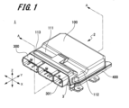
- FIG. 1 is a perspective view of an electronic control device according to a first embodiment
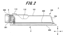
- 2 is a cross-sectional view taken along line AA shown in FIG. 1.
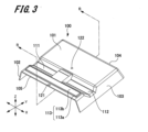
- FIG. 2 is a perspective view of a plastic housing according to the first embodiment.
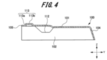
- 4 is a cross-sectional view taken along line BB shown in FIG. 3.
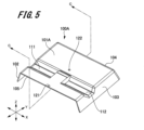
- FIG. 11 is a perspective view of a resin housing in a conventional electronic control device.
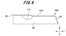
- 6 is a cross-sectional view taken along line CC shown in FIG. 5.
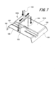
- FIG. 2 is a diagram illustrating a resin flow path and a resin casing in a mold.
- FIG. 2 is a diagram illustrating fiber orientation and shrinkage anisotropy during injection molding.
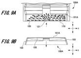
- 1A and 1B are diagrams illustrating the flow of resin and fiber orientation when a conventional resin housing is injection molded.
- 3A to 3C are diagrams illustrating the flow of resin and fiber orientation when the resin housing of the first embodiment is injection molded.
- 5A to 5C are diagrams illustrating the relationship between the height of a step portion and the amount of displacement of warping at the center of an opening-forming wall panel in the plastic casing of the first embodiment.
- 5A to 5C are diagrams illustrating the relationship between the width of a step portion in the plastic casing of the first embodiment and the amount of displacement of warping at the center of an opening-forming wall panel.
- 10A and 10B are diagrams illustrating cross-sectional shapes and external forces of opening-forming wall plates of a conventional plastic casing and the plastic casing of the first embodiment.
- FIG. 11 is a perspective view of a plastic housing according to a second embodiment.
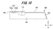
- 15 is a cross-sectional view taken along line DD shown in FIG. 14.
- FIG. Fig. 1 is a perspective view of an electronic control device according to a first embodiment of the present invention
- Fig. 2 is a cross-sectional view taken along line AA shown in Fig. 1.
- the electronic control unit 1 receives electrical signals from various sensors installed inside the vehicle and detects conditions such as air flow rate, temperature, and pressure. The electronic control unit 1 also calculates the fuel injection amount and ignition timing to optimize fuel efficiency and power according to the air flow rate, temperature, pressure, and other conditions. The electronic control unit 1 then outputs control signals generated based on the fuel injection amount and ignition timing to each electrical component such as the engine and transmission.
- the electronic control device 1 includes a plastic housing 100, an electronic circuit board 200, a connector 300, and a base 400.
- the plastic housing 100 and the base 400 form a hollow, flat housing 2.
- the housing 2 has an opening 3 on one side.
- the base 400 is formed into a plate shape, for example, by aluminum die casting or sheet metal.
- the base 400 forms one side of the housing 2, and the plastic housing 100 forms four sides of the housing 2.
- the direction approximately perpendicular to the opening 3 of the housing 2 is referred to as the first direction Y. Furthermore, the direction approximately perpendicular to the first direction Y and parallel to the opening 3 is referred to as the second direction X. Furthermore, the direction approximately perpendicular to the first direction Y and the second direction X is referred to as the third direction Z.
- the third direction Z indicates the thickness direction of the flat housing 2.
- the electronic circuit board 200 is disposed inside the housing 2.
- the electronic circuit board 200 is fixed to the base 400 using screws or adhesive.
- Electronic components such as a microcomputer, semiconductor chips, and capacitors are mounted on the electronic circuit board 200.
- the connector 300 corresponds to the electrical component according to the present invention.
- the connector 300 passes through the opening 3 of the housing 2.
- the connector 300 has connector pins 301.
- the connector pins 301 of the connector 300 are electrically connected to the electronic circuit board 200 by soldering, press-fit connection, or the like.
- the plastic housing 100 is fixed to the base 400 by thermal caulking or screws.
- the spaces between the plastic housing 100 and the base 400, between the connector 300 and the plastic housing 100, and between the connector 300 and the base 400 are sealed with a sealant such as an adhesive. This prevents the housing 2 from infiltrating liquids, dust, etc. from the outside. As a result, the housing 2 protects the electronic circuit board 200 from liquids, dust, etc.
- FIGS. Fig. 3 is a perspective view of the plastic housing 100.
- Fig. 4 is a cross-sectional view taken along line BB shown in Fig. 3.
- the plastic housing 100 is formed in the shape of a housing with two openings.
- the plastic housing 100 has a first wall plate 101, a second wall plate 102, a third wall plate 103, and a fourth wall plate 104.
- the first wall plate 101 faces the base 400 in the third direction Z.
- the second wall plate 102 faces the third wall plate 103 in the second direction X.
- the fourth wall plate 104 faces the opening 3 in the first direction Y.
- the first wall plate 101 corresponds to the opening-forming wall plate according to the present invention.
- One side of the first wall plate 101 in the first direction Y is an end surface 105 that forms the opening 3.
- the other side of the first wall plate 101 in the first direction Y is continuous with the fourth wall plate 104.
- the first wall plate 101 is formed with recesses 111, 112 and a step portion 113 that is convex on the outer surface side.
- the recesses 111 and 112 are located in the middle of the first wall panel 101 in the first direction Y.
- the recesses 111 and 112 are arranged side by side at an appropriate distance in the second direction X.
- One end of the recess 111 in the second direction X reaches the second wall panel 102.
- One end of the recess 112 in the second direction X reaches the third wall panel 103.
- the step 113 is located between the recesses 111, 112 and the end face 105.
- the step 113 has a rising piece 113a that protrudes approximately perpendicularly from the outer surface of the first wall panel 101, and a plate-like flat piece 113b that is parallel to the first wall panel 101.
- the flat piece 113b of the step 113 is formed into a rectangle that is long in the second direction X.
- the rising piece 113a is continuous with the four sides of the flat piece 113b.
- the thickness of the step 113 is set to be the same as the thickness of the other parts of the first wall panel 101. Therefore, providing the step 113 in the first wall panel 101 allows for a reduction in the amount of resin compared to providing the first wall panel 101 with a thicker part that is thicker than the other parts. As a result, the increase in weight of the plastic housing 100 is suppressed. In addition, because the step 113 has a convex shape on the outer surface side, interference with electronic components mounted on the electronic circuit board 200 can be avoided.
- the plastic housing 100 is made of an engineering plastic that contains fibers.
- the plastic material of the plastic housing 100 is, for example, polybutylene terephthalate containing 30% glass fiber (GF). This allows the plastic housing 100 to be lighter than a plastic housing made of aluminum die-cast or sheet metal, and also reduces production costs. Furthermore, the plastic housing 100 can ensure the desired strength.
- the plastic housing 100 is manufactured by injection molding. In injection molding, resin is injected from a first gate and a second gate of a mold.
- a first wall panel 101 of the plastic housing 100 has a first gate position 121 that faces the first gate of the mold, and a second gate position 122 that faces the second gate of the mold. Gate marks are formed at the first gate position 121 and the second gate position 122 of the first wall panel 101.
- the first gate position 121 is located between the end face 105 of the first wall panel 101 and the step 113 in the first direction Y. Therefore, in injection molding, the resin filled from the first gate advances toward the step 113.
- the second gate position 122 is located between the end of the first wall panel 101 on the fourth wall panel side and the recesses 111, 112 in the first direction Y.
- FIGS. Fig. 5 is a perspective view of a resin housing in a conventional electronic control device
- Fig. 6 is a cross-sectional view taken along line CC shown in Fig. 5.
- a conventional electronic control device (not shown) includes a plastic housing 100A, an electronic circuit board 200, a connector 300, and a base 400. That is, the difference between the conventional electronic control device and the electronic control device 1 of this embodiment is the plastic housing 100A. As shown in Figures 5 and 6, the plastic housing 100A includes a first wall plate 101A, a second wall plate 102, a third wall plate 103, and a fourth wall plate 104.
- the first wall panel 101A faces the base 400 in the third direction Z.
- One side of the first wall panel 101A in the first direction Y is an end surface 105.
- the other side of the first wall panel 101A in the first direction Y is continuous with the fourth wall panel 104.
- the first wall panel 101A has recesses 111 and 112 formed therein. In other words, the first wall panel 101A does not have a step portion 113 (see Figures 3 and 4).
- the plastic housing 100A is made of engineering plastic containing fibers.
- the plastic housing 100A is manufactured by injection molding. In injection molding, resin is injected from a first gate and a second gate of a mold.
- a first wall panel 101A of the plastic housing 100A has a first gate position 121 that faces the first gate of the mold, and a second gate position 122 that faces the second gate of the mold. Gate marks are formed at the first gate position 121 and the second gate position 122 of the first wall panel 101A.
- FIG. 7 is a diagram for explaining a resin flow path and a resin housing in a mold.
- the mold used for injection molding shown in Figure 7 is a two-point pin gate type. If the size of the casing is to a certain extent, or if high precision is required for the shape, a multi-point gate type with two or more points is used to compensate for pressure loss in the resin flow.
- a multi-point gate type with two or more points is used to compensate for pressure loss in the resin flow.
- the resin injected from the injection molding machine passes through the sprue 151, runner 152, first gate 153, and second gate 154, which are the resin flow paths within the mold, and fills the gaps in the housing formation area.
- the filled resin is solidified through a cooling process.
- the mold is then opened, and the sprue 151, runner 152, first gate 153, and second gate 154 are separated from the solidified resin, and the molded product, resin housing 100A, is removed.
- the plastic housing 100A thermally shrinks during the cooling process of injection molding and after the plastic housing 100A is removed from the mold.
- the amount of thermal shrinkage is not constant in all parts of the plastic housing 100A.
- the amount of thermal shrinkage at each location in the plastic housing 100A varies depending on the difference in volume of each location in the plastic housing 100A, the difference in cooling speed at each location in the mold, and the difference in the degree of fiber orientation contained. And because there is a difference in the amount of thermal shrinkage at each location, warping (distortion) occurs in the first wall panel 101A of the plastic housing 100A, for example.
- the direction and amount of warping of the injection-molded plastic housing 100A is first measured. After that, the type of warping that will occur is predicted and the product dimensions in the mold are corrected.
- FIG. 8 is a diagram for explaining fiber orientation and shrinkage anisotropy during injection molding.
- the glass fiber fibers 161 contained in the resin are highly oriented in the flow direction 162 of the resin due to the shear force during injection molding.
- the longitudinal direction of the glass fiber fibers 161 is approximately parallel to the flow direction 162 of the resin.
- the strength of the glass fiber fibers 161 in the longitudinal direction is greater than the strength in the lateral direction.
- the amount of shrinkage 163 in the direction parallel to the resin flow direction 162 is smaller than the amount of shrinkage 164 in the direction perpendicular to the resin flow direction 162. This causes anisotropy in the shrinkage of the injection-molded resin. As a result, warping occurs in part of the resin molded product.
- FIGS. 9A and 9B and FIGS. 10A and 10B are diagrams illustrating the flow of resin and fiber orientation when injection molding a conventional plastic housing 100A.
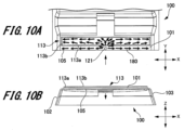
- Fig. 10A and 10B are diagrams illustrating the flow of resin and fiber orientation when injection molding the plastic housing 100 of the present embodiment.
- the resin housing 100A when the resin housing 100A is injection molded, the resin is filled from the first gate position 121 of the first wall panel 101A and flows radially.
- the glass fiber fibers are oriented in the same direction as the flow direction 170 of the resin. This causes anisotropic shrinkage on the end surface 105 side of the first wall panel 101A.
- the resin is filled from the first gate position 121 of the first wall panel 101 and reaches the rising piece 113a of the step portion 113.
- the resin then flows in the second direction X along the rising piece 113a.
- the glass fiber fibers are then oriented in the same direction as the flow direction 180 of the resin. This aligns the fiber orientation of the glass fiber fibers in the flow direction 180 of the resin (second direction X). As a result, shrinkage of the first wall panel 101 in the second direction X is suppressed.
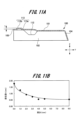
- Fig. 11A is a cross-sectional view showing the height of a step 113 in a plastic housing 100.
- Fig. 11B is a graph illustrating the relationship between the height of the step 113 and the amount of displacement of the warp at the center of the first wall panel 101.
- the distance in the third direction Z from the outer surface of the first wall panel 101 to the outer surface of the flat piece 113b in the step 113 is defined as the height t of the step 113.
- the amount of displacement in the third direction Z at the center of the first wall panel 101 in the second direction X is defined as the amount of warping displacement h.
- the relationship between the height t of the step 113 and the amount of warping displacement h was verified using a known resin flow simulation.
- the thickness of the first wall panel 101 was set to 1.6 mm
- the length of the step 113 in the second direction X was set to the maximum length that can be formed on the first wall panel 101 (140 mm in this embodiment).
- the warpage displacement h decreases. Furthermore, when the height t of the step 113 exceeds 5 mm, the warpage displacement h remains almost unchanged.
- the results of this resin flow simulation show that if the height t of the step 113 is 50% or more of the thickness of the first wall panel 101 (step 113), the warpage displacement h can be reduced by approximately 0.5 mm. Therefore, it was found that if the height t of the step 113 is 50% or more of the thickness of the first wall panel 101, the effect of suppressing the warpage of the first wall panel 101 can be obtained.
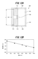
- Fig. 12A is a cross-sectional view showing the width of a step 113 in a plastic housing 100.
- Fig. 12B is a graph illustrating the relationship between the width of the step 113 and the amount of displacement of the warp at the center of the first wall panel 101.
- the length of the step 113 in the second direction X is defined as the width w of the step 113.
- the amount of displacement in the third direction Z at the center of the first wall panel 101 in the second direction X is defined as the amount of warping displacement h.
- the width w of the step 113 is the length of the rising piece 113a that the filled resin first reaches. In other words, the width w of the step 113 can also be said to be the length of the portion that first changes the progress of the filled resin.
- the relationship between the width w of the step 113 and the amount of warping displacement h was verified using a known resin flow simulation.
- the thickness of the first wall panel 101 (step 113) was set to 1.6 mm
- the height t of the step 113 was set to 3.0 mm.
- the maximum length of the step 113 in the second direction X was set to 140 mm.
- the results of the resin flow simulation show that increasing the width w of the step 113 reduces the warpage displacement h.
- the results of this resin flow simulation show that if the width w of the step 113 is 25% or more of the maximum length of the step 113 in the second direction X, the warpage displacement h can be reduced by approximately 0.3 mm. Therefore, it was found that if the width w of the step 113 is 25% or more of the length of the first wall panel 101 in the second direction X, the effect of suppressing the warpage of the first wall panel 101 can be obtained.
- the amount of warping on the end face 105 side of the first wall panel 101 can be reduced by appropriately setting the height t and width W of the step 113 formed in the first wall panel 101. That is, in this embodiment, the dimensions of the step 113 are parameterized to manufacture the mold parts of the plastic housing 100. As a result, in this embodiment, the warping of the first wall panel 101 can be easily corrected. Also, in this embodiment, because the dimensions of the step 113 are parameterized, it is possible to reduce the number of times the mold needs to be modified compared to the conventional case in which the mold is corrected based on the measurement results of the warping of the molded product.
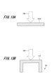
- FIGS. 13A and 13B are diagram showing the cross-sectional shape and external force of a conventional first wall panel 101A
- Fig. 13B is a diagram showing the cross-sectional shape and external force of the first wall panel 101 of this embodiment.
- the conventional first wall panel 101A has a flat plate shape.
- the step 113 of the first wall panel 101 of this embodiment is formed in a substantially C-shape. That is, the step 113 has a rising piece 113a and a flat piece 113b.
- the plate thickness of the first wall panels 101, 101A is set to the same (for example, 1.6 mm), and the height t of the step 113 is set to 3 mm.
- the geometrical moment of inertia was calculated when an external force 190 is applied to the step 113 of the conventional first wall panel 101A and the first wall panel 101 of this embodiment.
- the geometrical moment of inertia of the step 113 of the first wall panel 101 was 2.3 times the geometrical moment of inertia of the conventional first wall panel 101A. Therefore, by forming the step 113 in the first wall panel 101, the strength of the first wall panel 101 can be improved.
- the electronic control device according to the second embodiment differs from the electronic control device 1 according to the first embodiment in the plastic housing 500. Therefore, here, we will omit a description of the configuration common to the electronic control device 1 in the second embodiment and will only describe the plastic housing 500 according to the second embodiment.
- FIGS. Fig. 14 is a perspective view of the plastic housing 500.
- Fig. 15 is a cross-sectional view taken along line DD shown in Fig. 14.
- the plastic housing 500 is formed in the shape of a housing with two openings.
- the plastic housing 500 has a first wall plate 501, a second wall plate 102, a third wall plate 103, and a fourth wall plate 104.
- the first wall plate 501 faces the base 400 (see Figure 1) in the third direction Z.
- the first wall plate 501 corresponds to the opening forming wall plate according to the present invention.
- One side of the first wall plate 501 in the first direction Y is an end surface 505 that forms the opening 3.
- the other side of the first wall plate 501 in the first direction Y is continuous with the fourth wall plate 104.
- the first wall plate 501 is formed with recesses 111, 112 and a step portion 513 that is convex on the inner surface side.
- the recesses 111 and 112 are located in the middle of the first wall panel 501 in the first direction Y.
- the recesses 111 and 112 are arranged at an appropriate distance apart in the second direction X.
- One end of the recess 111 in the second direction X reaches the second wall panel 102.
- One end of the recess 112 in the second direction X reaches the third wall panel 103.
- the step portion 513 is located between the recesses 111, 112 and the end face 505.
- the step portion 513 has a rising piece 513a that protrudes approximately perpendicularly from the inner surface of the first wall panel 101, and a plate-like flat piece 513b that is parallel to the first wall panel 101.
- the flat piece 513b of the step portion 513 is formed into a rectangle that is long in the second direction X.
- the rising piece 513a is continuous with the four sides of the flat piece 513b.
- the thickness of the step 513 is set to be the same as the thickness of the other parts of the first wall panel 501. Therefore, providing the step 513 in the first wall panel 501 allows for a reduction in the amount of resin compared to providing the first wall panel 501 with a thicker part that is thicker than the other parts. As a result, the weight of the plastic housing 500 is suppressed from increasing.
- the step 513 also has a shape that is convex on the inner surface side. Therefore, the length of the plastic housing 500 in the third direction Z is set so that the step 513 does not interfere with the electronic components mounted on the electronic circuit board 200 (see FIG. 2).
- the plastic housing 500 is made of engineering plastic containing fibers. This allows the plastic housing 500 to be lighter than a housing made of aluminum die-cast or sheet metal, and also reduces production costs. Furthermore, the plastic housing 500 can ensure the desired strength.
- the plastic housing 500 is manufactured by injection molding.
- the first wall panel 101 of the plastic housing 100 has a first gate position 121 facing the first gate of the mold, and a second gate position 122 facing the second gate of the mold.
- the first gate position 121 is located between the end face 505 of the first wall panel 501 and the step portion 113 in the first direction Y.
- the second gate position 122 is located between the end of the first wall panel 501 on the fourth wall panel side and the recesses 111, 112 in the first direction Y. Gate marks are formed at the first gate position 121 and the second gate position 122 of the first wall panel 101.
- the fiber orientation of the glass fiber fibers is aligned in the resin flow direction (second direction X). This suppresses shrinkage of the first wall panel 101 in the second direction X, thereby suppressing warping of the first wall panel 501. As a result, the amount of warping (amount of displacement in the third direction Z) of the first wall panel 101 of the plastic housing 100 can be reduced compared to the first wall panel 101A of the conventional plastic housing 100A. In addition, because the step portion 513 is convex toward the inner surface side of the first wall panel 501, the plastic housing 500 can be made smaller.
- the shape of the step 113, 513 when viewed from the third direction Z is rectangular.
- the planar shape of the step according to the present invention is not limited to a rectangle, and may be other shapes such as an arc or a triangle.
- 1...Electronic control device 2...Housing, 3...Opening, 100, 500...Resin housing, 101, 501...First wall plate, 102...Second wall plate, 103...Third wall plate, 104...Fourth wall plate, 105, 505...End surface, 111, 112...Recess, 113, 513...Step portion, 113a...Rising piece, 113b...Flat plate piece, 121...First gate position , 122...second gate position, 151...sprue, 152...runner, 153...first gate, 154...second gate, 161...glass fiber, 162, 170, 180...flow direction, 163, 164...shrinkage amount, 190...external force, 200...electronic circuit board, 300...connector, 301...connector pin, 400...base
Landscapes
- Engineering & Computer Science (AREA)
- Manufacturing & Machinery (AREA)
- Mechanical Engineering (AREA)
- Casings For Electric Apparatus (AREA)
Abstract
Description
強化材繊維を配合した樹脂を射出成形する場合は、製品部を流動する樹脂に繊維の配向が発生する。これにより、樹脂の固化時に収縮の異方性が生じて、成形品の一部に反りが発生する。
なお、上述した以外の課題、構成および効果は、以下の実施形態の説明により明らかにされる。
以下、本発明の第1実施形態に係る電子制御装置について説明する。なお、各図において共通の部材には、同一の符号を付している。
まず、第1実施形態に係る電子制御装置の構成について、図1及び図2を用いて説明する。
図1は、第1実施形態に係る電子制御装置の斜視図である。図2は、図1に示すA-A線に沿う断面図である。
次に、樹脂筐体100の構成について、図3及び図4を用いて説明する。
図3は、樹脂筐体100の斜視図である。図4は、図3に示すB-B線に沿う断面図である。
次に、従来の電子制御装置における樹脂筐体の構成について、図5及び図6を用いて説明する。
図5は、従来の電子制御装置における樹脂筐体の斜視図である。図6は、図5に示すC-C線に沿う断面図である。
次に、樹脂筐体の金型内を樹脂が流動する流路について、図7を用いて説明する。
図7は、金型内の樹脂流路と樹脂筐体を説明する図である。
次に、射出成形時の繊維配向と収縮異方性について、図8を用いて説明する。
図8は、射出成形時の繊維配向と収縮異方性を説明する図である。
次に、樹脂筐体を射出成形する際の樹脂の流れと繊維配向について、図9A,B及び図10A,Bを用いて説明する。
図9A,Bは、従来の樹脂筐体100Aを射出成形する際の樹脂の流れと繊維配向を説明した図である。図10A,Bは、本実施形態の樹脂筐体100を射出成形する際の樹脂の流れと繊維配向を説明した図である。
次に、段部113の高さと第1壁板101の中央における反りの変位量について、図11A,Bを用いて説明する。
図11Aは、樹脂筐体100における段部113の高さを示す断面図である。図11Bは、段部113の高さと第1壁板101の中央における反りの変位量との関係を説明するグラフである。
次に、段部113の第2方向Xの長さと第1壁板101の中央における反りの変位量について、図12A,Bを用いて説明する。
図12Aは、樹脂筐体100における段部113の幅を示す断面図である。図12Bは、段部113の幅と第1壁板101の中央における反りの変位量との関係を説明するグラフである。
次に、従来の第1壁板101Aと本実施形態の第1壁板101に加わる外力について、図13A,Bを用いて説明する。
図13Aは、従来の第1壁板101Aの断面形状と外力を示す図である。図13Bは、本実施形態の第1壁板101の断面形状と外力を示す図である。
以下、本発明の第2実施形態に係る電子制御装置について説明する。なお、各図において共通の部材には、同一の符号を付している。
樹脂筐体500の構成について、図14及び図15を用いて説明する。
図14は、樹脂筐体500の斜視図である。図15は、図14に示すD-D線に沿う断面図である。
Claims (8)
- 繊維を含有した樹脂を射出成形して電子回路基板を収納する筐体状に形成され、電気部品が接続される開口部を有する樹脂筐体であって、
前記開口部を形成する開口形成壁板を有し、
前記開口形成壁板には、外面側又は内面側に凸となる段部が形成されている
樹脂筐体。 - 前記開口部の端面と前記段部との間にゲート痕を有する
請求項1に記載の樹脂筐体。 - 前記開口形成壁板において前記段部よりも前記開口部の端面と反対側の領域に、少なくとも1つ以上の第2ゲート痕を有する
請求項2に記載の樹脂筐体。 - 前記段部の厚みは、前記開口形成壁板の厚みと同一である
請求項1に記載の樹脂筐体。 - 前記段部の高さは、前記段部の板厚の50%以上に設定されている
請求項1に記載の樹脂筐体。 - 前記開口部の端面と前記段部を結ぶ方向と前記段部の高さ方向に直交する方向を幅方向とした場合に、前記段部の幅方向の長さは、前記開口形成壁板に形成可能な最大長の25%以上に設定されている
請求項1に記載の樹脂筐体。 - 前記段部と前記第2ゲート痕との間には、溝部が形成されている
請求項3記載の樹脂筐体。 - 電子回路基板と、
前記電子回路基板と電気的に接続される電気部品と、
繊維を含有した樹脂を射出成形して前記電子回路基板を収納する筐体状に形成され、前記電気部品が接続される開口部を有する樹脂筐体と、を備え、
前記樹脂筐体は、
前記開口部を形成する開口形成壁板を有し、
前記開口形成壁板には、外面側又は内面側に凸となる段部が形成されている
電子制御装置。
Priority Applications (2)
| Application Number | Priority Date | Filing Date | Title |
|---|---|---|---|
| JP2025526975A JPWO2024257239A1 (ja) | 2023-06-13 | 2023-06-13 | |
| PCT/JP2023/021976 WO2024257239A1 (ja) | 2023-06-13 | 2023-06-13 | 樹脂筐体及び電子制御装置 |
Applications Claiming Priority (1)
| Application Number | Priority Date | Filing Date | Title |
|---|---|---|---|
| PCT/JP2023/021976 WO2024257239A1 (ja) | 2023-06-13 | 2023-06-13 | 樹脂筐体及び電子制御装置 |
Publications (1)
| Publication Number | Publication Date |
|---|---|
| WO2024257239A1 true WO2024257239A1 (ja) | 2024-12-19 |
Family
ID=93851549
Family Applications (1)
| Application Number | Title | Priority Date | Filing Date |
|---|---|---|---|
| PCT/JP2023/021976 Ceased WO2024257239A1 (ja) | 2023-06-13 | 2023-06-13 | 樹脂筐体及び電子制御装置 |
Country Status (2)
| Country | Link |
|---|---|
| JP (1) | JPWO2024257239A1 (ja) |
| WO (1) | WO2024257239A1 (ja) |
Citations (1)
| Publication number | Priority date | Publication date | Assignee | Title |
|---|---|---|---|---|
| WO2018116710A1 (ja) * | 2016-12-22 | 2018-06-28 | 日立オートモティブシステムズ株式会社 | 電子制御装置 |
Family Cites Families (1)
| Publication number | Priority date | Publication date | Assignee | Title |
|---|---|---|---|---|
| JP7489891B2 (ja) * | 2020-10-13 | 2024-05-24 | 日立Astemo株式会社 | 樹脂筐体および電子制御装置 |
-
2023
- 2023-06-13 WO PCT/JP2023/021976 patent/WO2024257239A1/ja not_active Ceased
- 2023-06-13 JP JP2025526975A patent/JPWO2024257239A1/ja active Pending
Patent Citations (1)
| Publication number | Priority date | Publication date | Assignee | Title |
|---|---|---|---|---|
| WO2018116710A1 (ja) * | 2016-12-22 | 2018-06-28 | 日立オートモティブシステムズ株式会社 | 電子制御装置 |
Also Published As
| Publication number | Publication date |
|---|---|
| JPWO2024257239A1 (ja) | 2024-12-19 |
Similar Documents
| Publication | Publication Date | Title |
|---|---|---|
| EP1729373B1 (en) | Composite molding and molding process | |
| US8784715B2 (en) | Structure of parts made from plural composite pieces and method of building those parts | |
| JP5038273B2 (ja) | 樹脂モールド半導体センサ及び製造方法 | |
| US5909819A (en) | Box-shaped plastic housing of integrally molded resin | |
| US9960468B2 (en) | Metalized molded plastic components for millimeter wave electronics and method for manufacture | |
| WO2019230196A1 (ja) | モールド品の製造方法 | |
| US7192317B2 (en) | Detecting device and method of producing the same | |
| JP3173380B2 (ja) | 部材相互の射出成形による接続装置 | |
| EP1693176B1 (en) | Electronic device and method of producing the same | |
| JP4549406B2 (ja) | 電子部品搭載構造及び車載用センサー | |
| JP7489891B2 (ja) | 樹脂筐体および電子制御装置 | |
| JP2022008215A (ja) | 低反り射出成形ハウジング部品、およびそのようなハウジング部品を含む電気コネクタ | |
| CN112352474A (zh) | 树脂密封型车载电子控制装置 | |
| CN213617955U (zh) | 智能功率模块的模封模具下模、模封模具及智能功率模块 | |
| KR100859453B1 (ko) | 휴대폰배터리용 하우징 제조금형 및 이를 이용한 제조방법 | |
| CN113496956A (zh) | 半导体装置及半导体装置的制造方法 | |
| US8424959B2 (en) | Mould and cross member assembly, cross member and motor vehicle technical front panel | |
| JP2008302634A (ja) | 射出成形用金型 | |
| JP2002225067A (ja) | 多次成形体及びその製造方法 | |
| WO2014136336A1 (ja) | センサ装置 | |
| JP7710200B2 (ja) | コンデンサの製造方法及びコンデンサ | |
| US12169137B2 (en) | Airflow amount measuring device | |
| JP2002107201A (ja) | 流量測定装置 | |
| JP2713541B2 (ja) | パッケージ型固体電解コンデンサーの構造及びその製造方法 | |
| CN114986803A (zh) | 塑封模具的上模、塑封模具 |
Legal Events
| Date | Code | Title | Description |
|---|---|---|---|
| 121 | Ep: the epo has been informed by wipo that ep was designated in this application |
Ref document number: 23941546 Country of ref document: EP Kind code of ref document: A1 |
|
| ENP | Entry into the national phase |
Ref document number: 2025526975 Country of ref document: JP Kind code of ref document: A |
|
| WWE | Wipo information: entry into national phase |
Ref document number: 2025526975 Country of ref document: JP |
|
| NENP | Non-entry into the national phase |
Ref country code: DE |
|
| 122 | Ep: pct application non-entry in european phase |
Ref document number: 23941546 Country of ref document: EP Kind code of ref document: A1 |