WO2024257212A1 - かご位置検出装置及びエレベータ装置 - Google Patents
かご位置検出装置及びエレベータ装置 Download PDFInfo
- Publication number
- WO2024257212A1 WO2024257212A1 PCT/JP2023/021887 JP2023021887W WO2024257212A1 WO 2024257212 A1 WO2024257212 A1 WO 2024257212A1 JP 2023021887 W JP2023021887 W JP 2023021887W WO 2024257212 A1 WO2024257212 A1 WO 2024257212A1
- Authority
- WO
- WIPO (PCT)
- Prior art keywords
- position information
- unit
- detection unit
- car
- reference position
- Prior art date
- Legal status (The legal status is an assumption and is not a legal conclusion. Google has not performed a legal analysis and makes no representation as to the accuracy of the status listed.)
- Ceased
Links
Images





Classifications
-
- B—PERFORMING OPERATIONS; TRANSPORTING
- B66—HOISTING; LIFTING; HAULING
- B66B—ELEVATORS; ESCALATORS OR MOVING WALKWAYS
- B66B3/00—Applications of devices for indicating or signalling operating conditions of elevators
- B66B3/02—Position or depth indicators
Definitions
- This disclosure relates to a car position detection device and an elevator device.
- a conventional car position detection device is equipped with a magnetic tape stretched between the ceiling of the elevator shaft and the pit floor, and a detection unit that is fixed to the car and reads the scale recorded on the magnetic tape.
- the memory unit stores a table that records the magnetic scale value as the reference car position for each floor where the car lands (see, for example, Patent Document 1).
- the present disclosure has been made to solve the above-mentioned problems, and aims to provide a car position detection device and elevator system that can correct information that correlates the position in the elevator shaft with the car position information after the medium is extended, expanded, or replaced.
- the car position detection device includes a medium extending in the direction of movement of a car ascending and descending in a hoistway, a first detection unit fixed to the car and detecting car position information by reading the medium, a memory unit storing information associating a position in the hoistway with the car position information detected by the first detection unit as initial position information, a second detection unit fixed in the hoistway and detecting information detected by reading the medium at the fixed position as reference position information, and a correction unit correcting the initial position information when the reference position information detected by the second detection unit changes, based on the initial position information stored in the memory unit, the reference position information before the change detected by the second detection unit, and the reference position information after the change detected by the second detection unit.
- the elevator device includes a car that moves up and down in a hoistway, a medium extending in the direction of the car's movement, a first detection unit that is fixed to the car and detects position information of the car by reading the medium, a memory unit that stores information that associates a position in the hoistway with the position information of the car detected by the first detection unit as initial position information, a second detection unit that is fixed in the hoistway and detects the information detected by reading the medium at the fixed position as reference position information, and a correction unit that corrects the initial position information when the reference position information detected by the second detection unit changes, based on the initial position information stored in the memory unit, the reference position information before the change detected by the second detection unit, and the reference position information after the change detected by the second detection unit.
- the present disclosure provides a car position detection device and elevator device that can correct information that correlates the position in the elevator shaft with the car's position information after the medium is extended, expanded, or replaced.
- FIG. 2 is a side view of the elevator apparatus according to the first embodiment.
- FIG. 2 is a front view of an operation unit according to the first embodiment.
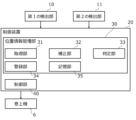
- FIG. 2 is a block diagram showing a control device according to the first embodiment.
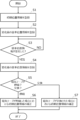
- 5 is a flowchart showing a process of a position information management unit of the control device in the first embodiment.
- a diagram showing the distances from the first floor to other floors stored in a memory unit in embodiment 1.
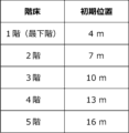
- 5 is a diagram showing initial position information stored in a storage unit in the first embodiment.
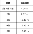
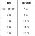
- FIG. 11A and 11B are diagrams showing corrected position information stored in a storage unit in the first embodiment when the magnetic tape expands or contracts.
- 11 is a diagram showing corrected position information when the magnetic tape stored in the storage unit in the first embodiment is replaced.
- FIG. 13 is a diagram showing corrected position information stored in a storage unit in a modification of the first embodiment when the magnetic tape expands or contracts.
- FIG. 2 is a diagram illustrating a configuration example of a processing circuit of the
- Embodiment 1 The car position detection device and elevator device according to the first embodiment will be described in detail below. Note that the same reference numerals in the various drawings represent the same or equivalent components.
- the elevator system includes a car 1, a counterweight 2, a main rope 3, a car guide rail 4, a counterweight guide rail 5, a hoist 6, a deflector pulley 7, a spring 8, a magnetic tape 9, a first detection unit 10, a second detection unit 11, an operation unit 12, and a control device 20.
- the car position detection device in this embodiment includes the magnetic tape 9, the first detection unit 10, the second detection unit 11, and a position information management unit 30, which will be described later. Note that the operation unit 12 is not shown in FIG. 1.
- a car 1 and a counterweight 2 are provided in the hoistway 100.
- the car 1 is connected to one end of a main rope 3, and moves up and down in the hoistway 100 along a car guide rail 4 that extends vertically.
- the counterweight 2 is connected to the other end of the main rope 3, and moves up and down in the hoistway 100 along a counterweight guide rail 5 that extends vertically.
- the main rope 3 is wound around a sheave 6a and a deflector sheave 7 of the hoisting machine 6.
- a machine room 101 is provided at the top of the elevator shaft 100.
- a hoist 6 and a deflector sheave 7 are provided in the machine room 101.
- the hoist 6 has a sheave 6a and a motor (not shown), and the motor rotates the sheave 6a.
- the magnetic tape 9, which is the medium, is provided in the elevator 100 so as to extend along the direction of movement of the car 1. Specifically, one end of the magnetic tape 9 is fixed to the ceiling of the elevator 100, and the other end is connected to a spring 8 provided on the bottom surface of the elevator 100. The direction of movement of the car 1 is the vertical direction. Code information is recorded on the magnetic tape 9, and the magnetic tape 9 is provided so that the value of the code information increases from the bottom to the top in the vertical direction.
- the magnetic tape 9 may be attached in the opposite direction.
- the magnetic tape 9 may also be fixed to the ceiling of the elevator 100 via a metal fitting such as a bracket.
- the first detection unit 10 is fixed to the car 1 and detects the position information of the car 1 by reading the code information recorded on the magnetic tape 9.
- the first detection unit 10 is, for example, a magnetic sensor.
- the first detection unit 10 outputs the position information of the car 1 to the acquisition unit 31 described later via an input/output interface (not shown).
- the second detection unit 11 is fixed within the elevator shaft 100. Specifically, the second detection unit 11 is fixed to the car guide rail 4, and is preferably fixed below the midpoint of the movable range of the car 1 in the moving direction of the car 1. For example, when the car 1 can move from an upper end switch (not shown) located above the top floor to a lower end switch (not shown) located below the bottom floor, the movable range of the car 1 is the range from the upper end switch to the lower end switch. The second detection unit 11 is fixed below the midpoint of that range, that is, on the lower end switch side.
- the second detection unit 11 is fixed in the vicinity of the lowest floor on which car 1 can land.
- the vicinity of the lowest floor is, for example, the range from the floor one level below the lowest floor to the floor one level above the lowest floor.
- the vicinity of the lowest floor is, for example, the range from the pit to the floor one level above the lowest floor.
- the lowest floor on which car 1 can land is also simply referred to as the lowest floor.
- the second detection unit 11 detects information detected by reading code information recorded on the magnetic tape 9 at a fixed position of the second detection unit 11 as reference position information.
- the second detection unit 11 is, for example, a magnetic sensor.
- the second detection unit 11 outputs the reference position information to the acquisition unit 31 described later via an input/output interface (not shown).
- the operation unit 12 is provided, for example, in the car 1 and is connected to the control device 20 by wire. As shown in FIG. 2, the operation unit 12 has a changeover switch 12a, an up button 12b, a down button 12c, and a registration button 12d.
- the changeover switch 12a is a switch for switching the operation mode of car 1.
- the operation unit 12 When the changeover switch 12a is switched from the normal operation mode to the inspection operation mode by an operator, the operation unit 12 outputs an inspection operation signal, which is an electrical signal indicating that the operation mode of car 1 is to be switched to the inspection operation mode, to the control unit 40 described later. Also, when the changeover switch 12a is switched from the inspection operation mode to the normal operation mode by an operator, the operation unit 12 outputs a normal operation signal, which is an electrical signal indicating that the operation mode of car 1 is to be switched to the normal operation mode, to the control unit 40 described later.
- the operation unit 12 outputs an up signal, which is an electrical signal indicating that the car 1 should be moved upward, to the control unit 40 (described later) only while the worker is pressing the up button 12b.
- the operation unit 12 also outputs a down signal, which is an electrical signal indicating that the car 1 should be moved downward, to the control unit 40 (described later) only while the worker is pressing the down button 12c.
- the registration button 12d When the worker presses the registration button 12d, the operation unit 12 outputs a registration signal, which is an electrical signal indicating that the initial position (described later) should be registered, to the registration unit 34 (described later).
- the control device 20 is a device such as a control board that is composed of a processor including a semiconductor integrated circuit, a memory, and an input/output interface, and controls the entire elevator device. An example of the configuration of the processing circuit of the control device 20 will be described later. As shown in FIG. 3, the control device 20 includes a position information management unit 30 and a control unit 40.
- the location information management unit 30 has an acquisition unit 31, a correction unit 32, a determination unit 33, a registration unit 34, and a storage unit 35.
- the acquisition unit 31 has a software module that acquires the position information of the cage 1 from the first detection unit 10 and the reference position information from the second detection unit 11.
- the correction unit 32 includes a software module that corrects the initial position information, which will be described later, based on the initial position information, the reference position information before the change, and the reference position information after the change, which will be described later.
- the determination unit 33 includes a software module that determines whether the reference position information has changed.
- the determination unit 33 also includes a software module that determines whether the reference position information has changed due to expansion or contraction of the magnetic tape 9, or due to replacement of the magnetic tape 9.
- the registration unit 34 includes a software module that registers the initial location information described below.
- the registration unit 34 also includes a software module that registers the reference location information acquired by the acquisition unit 31.
- the memory unit 35 is a storage device composed of a volatile or non-volatile memory.
- the memory unit 35 stores information associating each floor with an initial position as initial position information.
- the memory unit 35 also stores information associating each floor with a corrected position as corrected position information.
- the memory unit 35 also stores reference position information. Furthermore, the memory unit 35 pre-stores the distance from the reference floor to other floors that are floors other than the reference floor.
- the reference floor and other floors are floors on which the car 1 can land. In this embodiment, the reference floor is the lowest floor.
- the control unit 40 is equipped with a software module that controls the movement of car 1 in an operation mode selected by the changeover switch 12a of the operation unit 12.
- the normal operation mode is a normal mode selected for the movement of users, and is an operation mode in which car 1 is moved according to call registration.
- the inspection operation mode is a mode selected during maintenance inspection, and is an operation mode in which car 1 is moved according to manual operation by an operator.
- the control unit 40 also has a software module that notifies the determination unit 33 of the operation mode of car 1.
- FIG. 4 is a flowchart showing the processing of the control device 20.
- step S1 the registration unit 34 registers the initial position information.
- the registration unit 34 stores information associating each floor with the initial position in the storage unit 35 as the initial position information.
- an operator switches the operation mode of car 1 to the inspection operation mode using the changeover switch 12a of the operation unit 12, and presses the up button 12b or the down button 12c to move car 1 to the lowest floor, which is the reference floor.
- the control unit 40 controls the movement of car 1 in the inspection operation mode. While the control unit 40 is receiving an up signal or down signal output from the operation unit 12, it controls the hoist 6 to raise or lower car 1.
- the worker presses the registration button 12d on the operation unit 12.
- the operation unit 12 outputs a registration signal to the registration unit 34.
- the registration unit 34 receives the registration signal, it associates the position information of car 1 acquired by the acquisition unit 31 with the lowest floor as an initial position and stores it in the memory unit 35.
- the registration unit 34 stores initial position information in the storage unit 35 based on the initial position corresponding to the lowest floor and the distance from the lowest floor to the other floors stored in advance in the storage unit 35.
- the storage unit 35 stores the distance from the 1st floor, which is the lowest floor, to the other floors.
- the left column of FIG. 5 shows the other floors, which are the 2nd floor to the 5th floor, and the right column shows the distance from the 1st floor to the other floors.
- the distance from the 1st floor to the 2nd floor is 3 m
- the distance from the 1st floor to the 3rd floor is 6 m
- the distance from the 1st floor to the 4th floor is 9 m
- the distance from the 1st floor to the 5th floor is 12 m, which are stored in the storage unit 35.
- the registration unit 34 adds these values to calculate the initial position corresponding to the 2nd floor. As shown in FIG. 6, the registration unit 34 stores the initial position corresponding to the 2nd floor, which is 7 m, in the storage unit 35.
- the initial position is calculated based on the position information of car 1 detected by the first detection unit 10 and the distance from the reference floor to the other floors stored in the memory unit 35.
- the first detection unit 10 can detect the position information of car 1 on the reference floor, it is possible to calculate the initial position corresponding to the other floors without detecting the position information of car 1 on the other floors.
- the initial position information can be quickly registered.
- step S2 the registration unit 34 registers the reference position information acquired by the acquisition unit 31. Specifically, the acquisition unit 31 acquires the reference position information detected by the second detection unit 11. The registration unit 34 stores this reference position information in the storage unit 35 as the reference position information before the change.
- the worker After the initial position information and the reference position information before the change are registered, the worker switches the operation mode of car 1 to the normal operation mode using the changeover switch 12a of the operation unit 12.
- the worker may switch the operation mode of car 1 to the inspection operation mode using the changeover switch 12a.
- step S3 the determination unit 33 determines whether the reference position information has changed. Specifically, the acquisition unit 31 periodically acquires the reference position information detected by the second detection unit 11. The determination unit 33 compares the reference position information acquired by the acquisition unit 31 in step S3 with the reference position information before the change stored in the storage unit 35. When the reference position information acquired by the acquisition unit 31 in step S3 is different from the reference position information before the change, the determination unit 33 determines that the reference position information has changed, and proceeds to step S4. When the reference position information acquired by the acquisition unit 31 in step S3 is equal to the reference position information before the change, the determination unit 33 determines that the reference position information has not changed, and proceeds to step S3.
- the determination unit 33 may determine that the reference position information has changed when there is a difference between the reference position information acquired by the acquisition unit 31 in step S3 and the reference position information before the change that is equal to or greater than a predetermined threshold.
- the acquisition unit 31 may acquire the reference position information irregularly rather than periodically.
- step S4 the registration unit 34 registers the reference position information acquired by the acquisition unit 31. Specifically, the acquisition unit 31 acquires the reference position information detected by the second detection unit 11. The registration unit 34 stores this reference position information in the storage unit 35 as the changed reference position information.
- step S5 the determination unit 33 determines whether the reference position information has changed due to expansion or contraction of the magnetic tape 9, or due to replacement of the magnetic tape 9. Specifically, the control unit 40 notifies the determination unit 33 of the operation mode of car 1.
- the determination unit 33 determines that the reference position information has changed due to expansion or contraction of the magnetic tape 9, and proceeds to step S6.
- the determination unit 33 determines that the reference position information has changed due to replacement of the magnetic tape 9, and proceeds to step S7.
- step S6 the correction unit 32 corrects the initial position information based on the initial position information, the reference position information before the change, the reference position information after the change, and the distance from one end of the magnetic tape 9 to the second detection unit 11 in the moving direction of the car 1.
- the correction of the initial position information is performed when the magnetic tape 9 expands or contracts.
- the correction unit 32 calculates a corrected position by correcting the initial position corresponding to each floor from the initial position information, and stores information correlating each floor with the corrected position in the memory unit 35 as corrected position information.
- the corrected position information is information obtained by correcting the initial position information.
- the formula for calculating the corrected position to correct the initial position information is shown below.
- the amount of change in the reference position information " ⁇ x” is calculated by subtracting the reference position information "x1" before the change from the reference position information "x2" after the change. As shown in Equation 2, the amount of change in the reference position information " ⁇ x” is added to the distance "L” from one end of the magnetic tape 9 to the second detection unit 11 in the vertical direction, then divided by the distance "L” and multiplied by the initial position "a", to calculate the corrected position "a'".
- the correction unit 32 calculates the amount of change ⁇ x in the reference position information to be 0.2 m using Equation 1.
- the correction unit 32 calculates the corrected position a' corresponding to the first floor using formula 2. As shown in FIG. 6, the initial position a corresponding to the first floor is 4 m. The correction unit 32 calculates the corrected position a' corresponding to the first floor to be 4.04 m using formula 2. The corrected positions a' corresponding to the other floors can also be calculated in a similar manner using formula 2. After calculating the corrected position, the correction unit 32 stores information associating each floor with the corrected position in the memory unit 35 as corrected position information, as shown in FIG. 7. Then, the process ends.
- step S7 the correction unit 32 corrects the initial position information based on the initial position information, the reference position information before the change, and the reference position information after the change.
- step S7 the correction of the initial position information when the magnetic tape 9 is replaced is performed. Specifically, the correction unit 32 calculates a corrected position by correcting the initial position corresponding to each floor from the initial position information, and stores information correlating each floor with the corrected position in the storage unit 35 as corrected position information.
- the corrected position information is information obtained by correcting the initial position information.
- the formula for calculating the corrected position to correct the initial position information is shown below.
- the corrected position "a'" is calculated by subtracting the reference position information "x1" before the change from the initial position "a” and then adding the reference position information "x2" after the change.
- the correction unit 32 calculates the corrected position a' corresponding to the first floor using Equation 3. As shown in FIG. 6, the initial position a corresponding to the first floor is 4 m. The correction unit 32 calculates the corrected position a' corresponding to the first floor to be 4 m using Equation 3. The corrected positions a' corresponding to other floors can also be calculated in a similar manner using Equation 3. After calculating the corrected position, the correction unit 32 stores information associating each floor with the corrected position in the memory unit 35 as corrected position information, as shown in FIG. 8. Then, the process ends.
- the control unit 40 controls the movement of the cage 1 using corrected position information, which is information obtained by correcting the initial position information.
- the car position detection device and elevator device include a second detection unit that is fixed in the elevator shaft 100 and detects information detected by reading the magnetic tape 9 at the fixed position as reference position information, and a correction unit 32 that corrects the initial position information when the reference position information detected by the second detection unit 11 changes, based on the initial position information stored in the memory unit 35, the reference position information before the change detected by the second detection unit 11, and the reference position information after the change detected by the second detection unit 11. Therefore, the initial position information can be corrected after the magnetic tape 9 is extended or contracted or replaced. Then, the control unit 40 controls the movement of the car 1 using the corrected position information, which is information obtained by correcting the initial position information, thereby preventing the car 1 from moving to a position deviated from the expected position.
- the second detection unit 11 is fixed below the midpoint of the movable range of the car 1 in the moving direction of the car 1. Compared to when the second detection unit 11 is fixed above the midpoint, the amount of change in the reference position information when the magnetic tape 9 expands or contracts tends to be larger. Therefore, the influence of measurement errors that depend on the equipment used as the second detection unit 11 can be suppressed. Furthermore, when the second detection unit 11 is fixed near the lowest floor, the influence of measurement errors that depend on the equipment used as the second detection unit 11 can be further suppressed.
- the car position detection device and elevator device include a determination unit 33 that determines whether the reference position information has changed due to expansion or contraction of the magnetic tape 9 or due to replacement of the magnetic tape 9.
- the initial position information can be appropriately corrected based on the determination result of the determination unit 33.
- the medium may have optical characteristics, mechanical shapes or properties, a geometric pattern shape represented on the surface, etc.
- the first detection unit 10 and the second detection unit 11 may be an image sensor, a magnetostrictive sensor, an optical sensor, etc.
- the operation unit 12 may also be connected to the control device 20 wirelessly.
- the operation unit 12 may be a mobile terminal such as a smartphone.
- the operation unit 12 may output an electrical signal such as a registration signal by infrared rays. Furthermore, the operation unit 12 does not have to be provided in the car 1. If the elevator device is not provided with the operation unit 12, for example, the control device 20 may have a changeover switch 12a, an up button 12b, a down button 12c, and a registration button 12d.
- the position information management unit 30 may also be provided in other equipment of the elevator system.
- the reference floor may be a floor other than the lowest floor.
- the registration unit 34 may register the initial position information based only on the position information of the car 1, without using the distance from the reference floor to the other floors. Specifically, an operator may move the car 1 using the operation unit 12 and stop it at each floor in order, and the position information of the car 1 detected by the first detection unit 10 in the stopped state may be stored in the memory unit 35 as the initial position corresponding to each floor.
- the corrected position may be calculated using the following formula 4 instead of formulas 1 and 2.
- the correction unit 32 may correct the initial position information based on the initial position information, the reference position information before the change, the reference position information after the change, and the total length of the magnetic tape 9 when the magnetic tape 9 is installed in the elevator shaft 100.
- the corrected position "a'" is calculated by subtracting the reference position information "x1" before the change from the total length "D" of the magnetic tape 9 when the magnetic tape 9 is installed in the elevator 100, dividing the result by the value obtained by subtracting the reference position information "x2" after the change from the total length "D", and then multiplying the result by the initial position "a".
- the correction unit 32 calculates the corrected position a' corresponding to the first floor using Equation 4. As shown in FIG. 6, the initial position a corresponding to the first floor is 4 m. The correction unit 32 calculates the corrected position a' corresponding to the first floor to be 4.04 m using Equation 3. The corrected positions a' corresponding to the other floors can be calculated in the same manner using Equation 4. After calculating the corrected position, the correction unit 32 stores information associating each floor with the corrected position in the memory unit 35 as corrected position information, as shown in FIG. 9.
- the formulas for calculating the corrected position when the magnetic tape 9 expands or contracts or when the magnetic tape 9 is replaced are not limited to formulas 1 to 4.
- the corrected position may be calculated using a formula that takes into account the temperature distribution in the elevator 100 or the strength of the magnetic tape 9.
- the corrected position information does not have to be stored in the memory unit 35.
- the corrected position corresponding to each floor may be calculated sequentially, and the initial position information may be corrected.
- Figure 10 is a diagram showing an example of the configuration of the processing circuit of the control device 20 in embodiment 1.
- Each function of the control device 20 can be realized by a processing circuit.
- the processing circuit includes at least one processor 51 and at least one memory 52.
- the processing circuit includes at least one dedicated hardware 53.
- each function of the control device 20 is realized by software, firmware, or a combination of software and firmware. At least one of the software and firmware is written as a program. At least one of the software and firmware is stored in at least one memory 52.
- the at least one processor 51 realizes the functions of the control device 20 by reading and executing the program stored in the at least one memory 52.
- the at least one processor 51 is also called a CPU, central processing unit, processing unit, arithmetic unit, microprocessor, microcomputer, or DSP.
- the at least one memory 52 is a non-volatile or volatile semiconductor memory such as a RAM, ROM, flash memory, EPROM, or EEPROM, a magnetic disk, a flexible disk, an optical disk, a compact disk, a mini disk, a DVD, or the like.
- a non-volatile or volatile semiconductor memory such as a RAM, ROM, flash memory, EPROM, or EEPROM, a magnetic disk, a flexible disk, an optical disk, a compact disk, a mini disk, a DVD, or the like.
- the processing circuit includes at least one dedicated hardware 53, the processing circuit is realized, for example, by a single circuit, a composite circuit, a programmed processor, a parallel programmed processor, an ASIC, an FPGA, or a combination of these.
- Each function of the control device 20 may be realized by a separate processing circuit, or all the functions of the control device 20 may be realized together by a single processing circuit.
- control device 20 may be realized by dedicated hardware 53, and other parts may be realized by software or firmware.
- the processing circuitry realizes each function of the control device 20 using hardware 53, software, firmware, or a combination of these.
Landscapes
- Indicating And Signalling Devices For Elevators (AREA)
Abstract
かご位置検出装置は、媒体(9)、第1の検出部(10)、記憶部、第2の検出部(11)及び補正部を備える。媒体(9)は、昇降路(100)内を昇降するかご(1)の移動方向に沿って延びる。第1の検出部(10)は、かご(1)に固定され、媒体(9)を読み取ることによりかご(1)の位置情報を検出する。記憶部は、昇降路(100)内における位置と第1の検出部(10)が検出したかご(1)の位置情報とを対応付けた情報を初期位置情報として記憶する。第2の検出部(11)は、昇降路(100)内に固定され、固定された位置において媒体(9)を読み取ることにより検出される情報を基準位置情報として検出する。補正部は、第2の検出部(11)が検出した基準位置情報が変化したとき、初期位置情報、変化前の基準位置情報、及び変化後の基準位置情報に基づいて初期位置情報を補正する。
Description
本開示は、かご位置検出装置及びエレベータ装置に関する。
従来のかご位置検出装置は、昇降路の天井とピット床との間に張架された磁気テープ、及びかごに固定され、磁気テープに記録された目盛りを読み取る検出部を備える。記憶部には、かごが着床する階床毎に磁気目盛りの値を基準かご位置として記憶したテーブルが格納されている(例えば、特許文献1参照)。
上記した従来のかご位置検出装置において、磁気テープ等の媒体が伸縮する又は交換されると、磁気目盛りの位置が元の位置からずれてしまう。磁気目盛りの位置が元の位置からずれた後にこの値に基づいてかごを移動制御すると、想定した位置からずれた位置にかごを移動させてしまうという課題があった。
本開示は上記した課題を解決するためになされたものであり、媒体の伸縮又は交換後、昇降路内における位置とかごの位置情報とが対応付けられた情報を補正することができるかご位置検出装置及びエレベータ装置を得ることを目的とするものである。
本開示にかかるかご位置検出装置は、昇降路内を昇降するかごの移動方向に沿って延びる媒体と、かごに固定され、媒体を読み取ることによりかごの位置情報を検出する第1の検出部と、昇降路内における位置と第1の検出部が検出したかごの位置情報とを対応付けた情報を初期位置情報として記憶する記憶部と、昇降路内に固定され、固定された位置において媒体を読み取ることにより検出される情報を基準位置情報として検出する第2の検出部と、第2の検出部が検出した基準位置情報が変化したとき、記憶部に記憶された初期位置情報、第2の検出部が検出した変化前の基準位置情報、及び第2の検出部が検出した変化後の基準位置情報に基づいて初期位置情報を補正する補正部と、を備える。
本開示にかかるエレベータ装置は、昇降路内を昇降するかごと、かごの移動方向に沿って延びる媒体と、かごに固定され、媒体を読み取ることによりかごの位置情報を検出する第1の検出部と、昇降路内における位置と第1の検出部が検出したかごの位置情報とを対応付けた情報を初期位置情報として記憶する記憶部と、昇降路内に固定され、固定された位置において媒体を読み取ることにより検出される情報を基準位置情報として検出する第2の検出部と、第2の検出部が検出した基準位置情報が変化したとき、記憶部に記憶された初期位置情報、第2の検出部が検出した変化前の基準位置情報、及び第2の検出部が検出した変化後の基準位置情報に基づいて初期位置情報を補正する補正部と、を備える。
本開示によれば、媒体の伸縮又は交換後、昇降路内における位置とかごの位置情報とが対応付けられた情報を補正することができるかご位置検出装置及びエレベータ装置を得ることができる。
実施の形態1.
以下に実施の形態1にかかるかご位置検出装置及びエレベータ装置を詳細に説明する。なお、各図面における同一の符号は同一又は相当の構成を表している。
以下に実施の形態1にかかるかご位置検出装置及びエレベータ装置を詳細に説明する。なお、各図面における同一の符号は同一又は相当の構成を表している。
図1に示すように、エレベータ装置は、かご1、釣合おもり2、主ロープ3、かごガイドレール4、釣合おもりガイドレール5、巻上機6、そらせ車7、バネ8、磁気テープ9、第1の検出部10、第2の検出部11、操作部12及び制御装置20を備える。本実施の形態におけるかご位置検出装置は、磁気テープ9、第1の検出部10、第2の検出部11、及び後述する位置情報管理部30を備える。なお、図1において操作部12の図示を省略している。
昇降路100内には、かご1及び釣合おもり2が設けられる。かご1は、主ロープ3の一端に接続され、鉛直方向に延びるかごガイドレール4に沿って昇降路100内を昇降する。釣合おもり2は、主ロープ3の他端に接続され、鉛直方向に延びる釣合おもりガイドレール5に沿って昇降路100内を昇降する。主ロープ3は、巻上機6の綱車6a及びそらせ車7に巻き掛けられる。
昇降路100の上部には、機械室101が設けられる。機械室101内には、巻上機6、そらせ車7が設けられる。巻上機6は、綱車6a及びモータ(図示せず)を有しており、モータが綱車6aを回転させる。
媒体である磁気テープ9は、かご1の移動方向に沿って延びるように昇降路100内に設けられる。具体的には、磁気テープ9は、その一端が昇降路100の天井に固定され、その他端が昇降路100の底面に設けられたバネ8に接続される。なお、かご1の移動方向とは、鉛直方向である。また、磁気テープ9にはコード情報が記録されており、鉛直方向の下側から上側に向かってコード情報の値が大きくなるように設けられている。なお、磁気テープ9を取り付ける向きは、この逆であってもよい。また、磁気テープ9は、ブラケット等の金具を介して昇降路100の天井に固定されていてもよい。
第1の検出部10は、かご1に固定され、磁気テープ9に記録されているコード情報を読み取ることによりかご1の位置情報を検出する。第1の検出部10は、例えば磁気センサである。第1の検出部10は、かご1の位置情報を入出力インタフェース(図示せず)を介して後述する取得部31に出力する。
第2の検出部11は、昇降路100内に固定される。具体的には、第2の検出部11は、かごガイドレール4に固定され、かご1の移動方向においてかご1の移動可能範囲の中間地点より下側に固定されるのが好ましい。例えば、かご1が最上階より上側に設けられた上終点スイッチ(図示せず)から最下階より下側に設けられた下終点スイッチ(図示せず)まで移動することができるとき、かご1の移動可能範囲は上終点スイッチから下終点スイッチまでの範囲となる。第2の検出部11は、当該範囲の中間地点より下側、つまり下終点スイッチ側に固定される。
また、第2の検出部11は、かご1が着床することができる最下階の近傍に固定されるのがより好ましい。当該最下階の近傍とは、例えば当該最下階の1つ下の階床から当該最下階の1つ上の階床までの範囲である。また、当該最下階の下側に他の階床がなくピットがある場合、当該最下階の近傍とは例えばピットから当該最下階の1つ上の階床までの範囲である。以下の説明において、かご1が着床することができる最下階を単に最下階とも呼ぶ。
第2の検出部11は、第2の検出部11が固定された位置において磁気テープ9に記録されているコード情報を読み取ることにより検出される情報を基準位置情報として検出する。第2の検出部11は、例えば磁気センサである。第2の検出部11は、基準位置情報を入出力インタフェース(図示せず)を介して後述する取得部31に出力する。
操作部12は、例えばかご1に設けられ、有線により制御装置20に接続される。図2に示すように、操作部12は、切替スイッチ12a、上昇ボタン12b、下降ボタン12c及び登録ボタン12dを有する。
切替スイッチ12aは、かご1の運転モードを切り替えるためのスイッチである。作業者により切替スイッチ12aが通常運転モードから点検運転モードに切り替えられると、操作部12は、かご1の運転モードを点検運転モードに切り替えることを示す電気信号である点検運転信号を後述する制御部40に出力する。また、作業者により切替スイッチ12aが点検運転モードから通常運転モードに切り替えられると、操作部12は、かご1の運転モードを通常運転モードに切り替えることを示す電気信号である通常運転信号を後述する制御部40に出力する。
操作部12は、作業者により上昇ボタン12bが押されている間のみ、かご1を上方へ移動させることを示す電気信号である上昇信号を後述する制御部40に出力する。また、操作部12は、作業者により下降ボタン12cが押されている間のみ、かご1を下方へ移動させることを示す電気信号である下降信号を後述する制御部40に出力する。操作部12は、作業者により登録ボタン12dが押されると、後述する初期位置を登録することを示す電気信号である登録信号を後述する登録部34に出力する。
制御装置20は、半導体の集積回路を含むプロセッサ、メモリ、及び入出力インタフェースにより構成される制御基板等の装置であり、エレベータ装置全体を制御する。制御装置20の処理回路の構成例については後に説明する。図3に示すように、制御装置20は、位置情報管理部30及び制御部40を備える。
位置情報管理部30は、取得部31、補正部32、判定部33、登録部34及び記憶部35を有する。
取得部31は、第1の検出部10からかご1の位置情報を、第2の検出部11から基準位置情報をそれぞれ取得するソフトウェアモジュールを備える。
補正部32は、後述する初期位置情報、変化前の基準位置情報、変化後の基準位置情報に基づいて後述する初期位置情報を補正するソフトウェアモジュールを備える。
判定部33は、基準位置情報が変化したかを判定するソフトウェアモジュールを備える。また、判定部33は、磁気テープ9の伸縮に起因して基準位置情報が変化したのか、磁気テープ9の交換に起因して基準位置情報が変化したのかを判定するソフトウェアモジュールを備える。
登録部34は、後述する初期位置情報を登録するソフトウェアモジュールを備える。また、登録部34は、取得部31が取得した基準位置情報を登録するソフトウェアモジュールを備える。
記憶部35は、揮発性又は不揮発性のメモリにより構成される記憶装置である。記憶部35は、各階床と初期位置とを対応付けた情報を初期位置情報として記憶する。また、記憶部35は、各階床と補正位置とを対応付けた情報を補正位置情報として記憶する。また、記憶部35は、基準位置情報を記憶する。さらに、記憶部35は、基準階床から基準階床以外の階床である他の階床までの距離を予め記憶している。基準階床及び他の階床は、かご1が着床することができる階床である。本実施の形態において、基準階床は最下階である。
制御部40は、操作部12の切替スイッチ12aによって選択された運転モードでかご1を移動制御するソフトウェアモジュールを備える。通常運転モードは、利用者の移動のために選択される通常のモードであり、呼び登録にしたがってかご1を移動させる運転モードである。点検運転モードは、保守点検時に選択されるモードであり、作業者による手動操作にしたがってかご1を移動させる運転モードである。また、制御部40は、かご1の運転モードを判定部33に通知するソフトウェアモジュールを備える。
次に本実施の形態にかかるかご位置検出装置及びエレベータ装置の動作について、図4を用いて説明する。図4は、制御装置20の処理を示すフローチャートである。
ステップS1において、登録部34は、初期位置情報を登録する。言い換えると、登録部34は、各階床と初期位置とを対応付けた情報を初期位置情報として記憶部35に記憶させる。
具体的には、まず、作業者が操作部12の切替スイッチ12aによりかご1の運転モードを点検運転モードに切り替えて、上昇ボタン12b又は下降ボタン12cを押してかご1を基準階床である最下階に移動させる。制御部40は、点検運転モードでかご1を移動制御する。制御部40は、操作部12から出力された上昇信号又は下降信号を受信している間、巻上機6を制御してかご1を上昇又は下降させる。
次に、かご1が最下階に停止した状態で作業者が操作部12の登録ボタン12dを押す。登録ボタン12dが押されると、操作部12が登録信号を登録部34に出力する。登録部34は、登録信号を受信したとき、取得部31が取得したかご1の位置情報を初期位置として最下階と対応付けて記憶部35に記憶させる。
最後に、登録部34は、最下階に対応する初期位置及び記憶部35に予め記憶された最下階から他の階床までの距離に基づいて、初期位置情報を記憶部35に記憶させる。図5に示すように、記憶部35には、最下階である1階から他の階床までの距離が記憶されている。図5の左列には、他の階床である2階から5階を示しており、右列には1階から他の階床までの距離を示している。1階から2階までの距離が3m、1階から3階までの距離が6m、1階から4階までの距離が9m及び1階から5階までの距離が12mと記憶部35に記憶されている。例えば、最下階である1階に対応する初期位置が4mであり、1階から2階までの距離が3mであると記憶部35に記憶されている場合、登録部34はこれらの値を加算して2階に対応する初期位置を算出する。登録部34は、図6に示すように、2階に対応する初期位置である7mを記憶部35に記憶させる。2階以外の他の階床についても、1階に対応する初期位置である4m及び記憶部35に記憶された1階から他の階床までの距離に基づいて同様に算出し、各階床と初期位置とを対応付けて記憶部35に記憶させることができる。図6の左列には、各階床を示しており、右列にはそれらに対応する初期位置を示している。
上述のように、初期位置は、第1の検出部10が検出したかご1の位置情報及び記憶部35に記憶された基準階床から他の階床までの距離に基づいて算出される。このように算出されることにより、第1の検出部10が基準階床におけるかご1の位置情報を検出することができれば、他の階床のかご1の位置情報を検出することなく、他の階床に対応する初期位置を算出することができる。つまり、かご1を他の階床に移動させることなく、他の階床に対応する初期位置を算出することができ、初期位置情報を迅速に登録することができる。
ステップS2において、登録部34は、取得部31が取得した基準位置情報を登録する。具体的には、取得部31が、第2の検出部11が検出した基準位置情報を取得する。登録部34は、この基準位置情報を変化前の基準位置情報として記憶部35に記憶させる。
初期位置情報及び変化前の基準位置情報が登録された後、作業者は操作部12の切替スイッチ12aによりかご1の運転モードを通常運転モードに切り替える。作業者は、エレベータ装置の点検又は磁気テープ9の交換等を行う際は、切替スイッチ12aによりかご1の運転モードを点検運転モードに切り替えることがある。
ステップS3において、判定部33は、基準位置情報が変化したか否かを判定する。具体的には、取得部31が、定期的に第2の検出部11が検出した基準位置情報を取得する。判定部33は、ステップS3において取得部31が取得した基準位置情報と、記憶部35に記憶された変化前の基準位置情報とを比較する。判定部33は、ステップS3において取得部31が取得した基準位置情報が変化前の基準位置情報と異なっているとき、基準位置情報が変化したと判定し、処理をステップS4へ進める。判定部33は、ステップS3において取得部31が取得した基準位置情報が変化前の基準位置情報と等しいとき、基準位置情報が変化していないと判定し、処理をステップS3へ進める。なお、判定部33は、ステップS3において取得部31が取得した基準位置情報と変化前の基準位置情報とに予め定められた閾値以上の差分があるとき、基準位置情報が変化したと判定してもよい。なお、取得部31は、定期的でなく、不定期に基準位置情報を取得してもよい。
ステップS4において、登録部34は、取得部31が取得した基準位置情報を登録する。具体的には、取得部31が、第2の検出部11が検出した基準位置情報を取得する。登録部34は、この基準位置情報を変化後の基準位置情報として記憶部35に記憶させる。
ステップS5において、判定部33は、磁気テープ9の伸縮に起因して基準位置情報が変化したのか、磁気テープ9の交換に起因して基準位置情報が変化したのかを判定する。具体的には、制御部40がかご1の運転モードを判定部33に通知する。判定部33は、かご1の運転モードが通常運転モードであるとき、磁気テープ9の伸縮に起因して基準位置情報が変化したと判定し、処理をステップS6へ進める。判定部33は、かご1の運転モードが点検運転モードであるとき、磁気テープ9の交換に起因して基準位置情報が変化したと判定し、処理をステップS7へ進める。
ステップS6において、補正部32は、初期位置情報、変化前の基準位置情報、変化後の基準位置情報及びかご1の移動方向における磁気テープ9の一端から第2の検出部11までの距離に基づいて初期位置情報を補正する。ステップS6では、磁気テープ9が伸縮した場合における初期位置情報の補正を行う。具体的には、補正部32は、初期位置情報のうち各階床に対応する初期位置を補正した補正位置を算出し、各階床と補正位置とを対応付けた情報を補正位置情報として記憶部35に記憶させる。なお、補正位置情報は、初期位置情報を補正した情報である。以下に、初期位置情報を補正するために補正位置を算出する数式を示す。


数式1に示すように、変化後の基準位置情報「x2」から変化前の基準位置情報「x1」を減算すると、基準位置情報の変化量「Δx」が算出される。数式2に示すように、鉛直方向における磁気テープ9の一端から第2の検出部11までの距離「L」に基準位置情報の変化量「Δx」を加算した後、当該距離「L」で除算し、初期位置「a」を乗算すると、補正位置「a’」が算出される。
初期位置情報が図6に示す通りであって、変化前の基準位置情報x1が1m、変化後の基準位置情報x2が1.2mであって、鉛直方向における磁気テープ9の一端から第2の検出部11までの距離Lが20mである場合において、各階床に対応する補正位置a’を算出する例を説明する。
まず、補正部32は、数式1より基準位置情報の変化量Δxを0.2mと算出する。
次に、補正部32は、数式2より1階に対応する補正位置a’を算出する。図6より、1階に対応する初期位置aは4mである。補正部32は、数式2より1階に対応する補正位置a’を4.04mと算出する。他の階床に対応する補正位置a’についても数式2より同様に算出することができる。補正部32は、補正位置を算出した後、図7に示すように各階床と補正位置とを対応付けた情報を補正位置情報として記憶部35に記憶させる。そして、処理を終了する。
ステップS7において、補正部32は、初期位置情報、変化前の基準位置情報及び変化後の基準位置情報に基づいて初期位置情報を補正する。ステップS7では、磁気テープ9が交換された場合における初期位置情報の補正を行う。具体的には、補正部32は、初期位置情報のうち各階床に対応する初期位置を補正した補正位置を算出し、各階床と補正位置とを対応付けた情報を補正位置情報として記憶部35に記憶させる。なお、補正位置情報は、初期位置情報を補正した情報である。以下に、初期位置情報を補正するために補正位置を算出する数式を示す。

数式3に示すように、初期位置「a」から変化前の基準位置情報「x1」を減算した後、変化後の基準位置情報「x2」を加算すると、補正位置「a’」が算出される。
初期位置情報が図6に示す通りであって、変化前の基準位置情報x1が1m、変化後の基準位置情報x2が2mである場合において、各階床に対応する補正位置a’を算出する例を説明する。
まず、補正部32は、数式3より1階に対応する補正位置a’を算出する。図6より、1階に対応する初期位置aは4mである。補正部32は、数式3より1階に対応する補正位置a’を4mと算出する。他の階床に対応する補正位置a’についても数式3より同様に算出することができる。補正部32は、補正位置を算出した後、図8に示すように各階床と補正位置とを対応付けた情報を補正位置情報として記憶部35に記憶させる。そして、処理を終了する。
補正部32により初期位置情報が補正された後、制御部40は、初期位置情報が補正された情報である補正位置情報を用いてかご1を移動制御する。
このような実施の形態1にかかるかご位置検出装置及びエレベータ装置にあっては、昇降路100内に固定され、固定された位置において磁気テープ9を読み取ることにより検出される情報を基準位置情報として検出する第2の検出部と、第2の検出部11が検出した基準位置情報が変化したとき、記憶部35に記憶された初期位置情報、第2の検出部11が検出した変化前の基準位置情報、及び第2の検出部11が検出した変化後の基準位置情報に基づいて初期位置情報を補正する補正部32を備える。そのため、磁気テープ9の伸縮又は交換後、初期位置情報を補正することができる。そして、制御部40が、初期位置情報が補正された情報である補正位置情報を用いてかご1を移動制御することにより、想定した位置からずれた位置にかご1を移動させることが抑制される。
さらに、このような実施の形態1にかかるかご位置検出装置及びエレベータ装置にあっては、第2の検出部11がかご1の移動方向においてかご1の移動可能範囲の中間地点より下側に固定される。第2の検出部11が当該中間地点より上側に固定される場合と比較して、磁気テープ9が伸縮したときの基準位置情報の変化量が大きくなる傾向にある。そのため、第2の検出部11として用いられる機器に依存する測定誤差による影響を抑制することができる。また、第2の検出部11が最下階の近傍に固定されると、第2の検出部11として用いられる機器に依存する測定誤差による影響をより抑制することができる。
さらに、このような実施の形態1にかかるかご位置検出装置及びエレベータ装置にあっては、磁気テープ9の伸縮に起因して基準位置情報が変化したのか、磁気テープ9の交換に起因して基準位置情報が変化したのかを判定する判定部33を備える。判定部33の判定結果に基づいて初期位置情報を適切に補正することができる。
媒体が磁気テープ9である例について説明したが、媒体は、光学的特性、機械的な形状や性質、表面に表された幾何学的パターン形状等を有するものであってもよい。また、第1の検出部10及び第2の検出部11は、画像センサ、磁歪センサ又は光学センサ等であってもよい。
操作部12が有線により制御装置20に接続される例について説明したが、操作部12が無線により制御装置20に接続されてもよい。操作部12は、スマートフォン等の携帯端末であってもよい。操作部12は、赤外線により登録信号等の電気信号を出力してもよい。また、操作部12は、かご1に設けられなくてもよい。エレベータ装置に操作部12が備えられていない場合、例えば制御装置20が切替スイッチ12a、上昇ボタン12b、下降ボタン12c及び登録ボタン12dを有していてもよい。
位置情報管理部30が制御装置20に備えられる例について説明したが、位置情報管理部30がエレベータ装置の他の機器に備えられていてもよい。
基準階床は、最下階以外の階床であってもよい。
登録部34は、基準階床から他の階床までの距離を用いずに、かご1の位置情報のみに基づいて初期位置情報を登録してもよい。具体的には、作業者が操作部12によりかご1を移動させて各階床に順番に停止させ、その停止した状態において第1の検出部10が検出したかご1の位置情報を各階床に対応する初期位置として記憶部35に記憶させてもよい。
初期位置及び補正位置が昇降路100内における位置として各階床に対応付けられて記憶部35に記憶される例について説明したが、これらの情報が昇降路100内における位置として昇降路100の底面からの距離等に対応付けられて記憶部35に記憶されてもよい。
数式1、2の代わりに下記の数式4を用いて補正位置を算出してもよい。つまり、補正部32は、初期位置情報、変化前の基準位置情報、変化後の基準位置情報及び磁気テープ9を昇降路100内に取り付けたときにおける磁気テープ9の全長に基づいて初期位置情報を補正してもよい。

数式4に示すように、磁気テープ9を昇降路100内に取り付けときにおける磁気テープ9の全長「D」から変化前の基準位置情報「x1」を減算した値を当該全長「D」から変化後の基準位置情報「x2」を減算した値で除算した後、初期位置「a」を乗算すると、補正位置「a’」が算出される。
初期位置情報が図6に示す通りであって、変化前の基準位置情報x1が1m、変化後の基準位置情報x2が1.2mであって、磁気テープ9を昇降路100内に取り付けたときにおける磁気テープ9の全長Dが20mである場合において、各階床に対応する補正位置a’を算出する例を説明する。
補正部32は、数式4より1階に対応する補正位置a’を算出する。図6より、1階に対応する初期位置aは4mである。補正部32は、数式3より1階に対応する補正位置a’を4.04mと算出する。他の階床に対応する補正位置a’についても数式4より同様に算出することができる。補正部32は、補正位置を算出した後、図9に示すように各階床と補正位置とを対応付けた情報を補正位置情報として記憶部35に記憶させる。
なお、磁気テープ9が伸縮した場合及び磁気テープ9が交換された場合における補正位置を算出する数式は、数式1から4に限定されない。例えば、昇降路100内における温度分布又は磁気テープ9の強度等を考慮した数式を用いて補正位置を算出してもよい。
補正位置情報は、記憶部35に記憶されなくてもよい。かご1の移動制御を行う際に各階床に対応する補正位置を逐次算出し、初期位置情報を補正してもよい。
図10を用いて、制御装置20の処理回路の構成例について説明する。図10は、実施の形態1における制御装置20の処理回路の構成例を示す図である。
制御装置20の各機能は、処理回路により実現し得る。例えば、処理回路は、少なくとも1つのプロセッサ51と少なくとも1つのメモリ52とを備える。また、例えば、処理回路は、少なくとも1つの専用のハードウェア53を備える。
処理回路が少なくとも1つのプロセッサ51と少なくとも1つのメモリ52とを備える場合、制御装置20の各機能は、ソフトウェア、ファームウェア、またはソフトウェアとファームウェアとの組み合わせで実現される。ソフトウェアおよびファームウェアの少なくとも一方は、プログラムとして記述される。ソフトウェアおよびファームウェアの少なくとも一方は、少なくとも1つのメモリ52に格納される。少なくとも1つのプロセッサ51は、少なくとも1つのメモリ52に記憶されたプログラムを読み出して実行することにより、制御装置20の機能を実現する。少なくとも1つのプロセッサ51は、CPU、中央処理装置、処理装置、演算装置、マイクロプロセッサ、マイクロコンピュータ、DSPともいう。例えば、少なくとも1つのメモリ52は、RAM、ROM、フラッシュメモリ、EPROM、EEPROM等の、不揮発性または揮発性の半導体メモリ、磁気ディスク、フレキシブルディスク、光ディスク、コンパクトディスク、ミニディスク、DVD等である。
処理回路が少なくとも1つの専用のハードウェア53を備える場合、処理回路は、例えば、単一回路、複合回路、プログラム化したプロセッサ、並列プログラム化したプロセッサ、ASIC、FPGA、またはこれらの組み合わせで実現される。制御装置20の各機能をそれぞれ1つずつの処理回路で実現してもよいし、制御装置20の各機能をまとめて1つの処理回路で実現してもよい。
制御装置20の各機能について、一部を専用のハードウェア53で実現し、他部をソフトウェアまたはファームウェアで実現してもよい。
このように、処理回路は、ハードウェア53、ソフトウェア、ファームウェア、またはこれらの組み合わせで制御装置20の各機能を実現する。
1 かご、2 釣合おもり、3 主ロープ、4 かごガイドレール、5 釣合おもりガイドレール、6 巻上機、6a 綱車、7 そらせ車、8 バネ、9 磁気テープ、10 第1の検出部、11 第2の検出部、12 操作部、12a 切替スイッチ、12b 上昇ボタン、12c 下降ボタン、12d 登録ボタン、20 制御装置、30 位置情報管理部、31 取得部、32 補正部、33 判定部、34 登録部、35 記憶部、40 制御部、100 昇降路、101 機械室
Claims (8)
- 昇降路内を昇降するかごの移動方向に沿って延びる媒体と、
前記かごに固定され、前記媒体を読み取ることにより前記かごの位置情報を検出する第1の検出部と、
前記昇降路内における位置と前記第1の検出部が検出した前記かごの前記位置情報とを対応付けた情報を初期位置情報として記憶する記憶部と、
前記昇降路内に固定され、固定された位置において前記媒体を読み取ることにより検出される情報を基準位置情報として検出する第2の検出部と、
前記第2の検出部が検出した前記基準位置情報が変化したとき、前記記憶部に記憶された前記初期位置情報、前記第2の検出部が検出した変化前の前記基準位置情報、及び前記第2の検出部が検出した変化後の前記基準位置情報に基づいて前記初期位置情報を補正する補正部と、
を備えたかご位置検出装置。 - 前記第2の検出部は、前記移動方向における前記かごの移動可能範囲の中間地点より下側に固定される請求項1に記載のかご位置検出装置。
- 前記第2の検出部は、前記かごが着床することができる最下階の近傍に固定される請求項2に記載のかご位置検出装置。
- 前記媒体の一端が前記昇降路の天井に固定され、
前記補正部は、前記第2の検出部が検出した前記基準位置情報が変化したとき、前記記憶部に記憶された前記初期位置情報、前記第2の検出部が検出した変化前の前記基準位置情報、前記第2の検出部が検出した変化後の前記基準位置情報、及び前記移動方向における前記媒体の一端から前記第2の検出部までの距離に基づいて前記初期位置情報を補正する請求項1から3のいずれか一項に記載のかご位置検出装置。 - 前記補正部は、前記第2の検出部が検出した前記基準位置情報が変化したとき、前記記憶部に記憶された前記初期位置情報、前記第2の検出部が検出した変化前の前記基準位置情報、前記第2の検出部が検出した変化後の前記基準位置情報、及び前記媒体を前記昇降路内に取り付けたときにおける前記媒体の全長に基づいて前記初期位置情報を補正する請求項1から3のいずれか一項に記載のかご位置検出装置。
- 前記媒体の伸縮に起因して前記基準位置情報が変化したのか、前記媒体の交換に起因して前記基準位置情報が変化したのかを判定する判定部をさらに備える請求項1から5のいずれか一項に記載のかご位置検出装置。
- 前記判定部は、前記かごの運転モードが呼び登録にしたがって前記かごを移動させる通常運転モードであるとき、前記媒体の伸縮に起因して前記基準位置情報が変化したと判定し、前記かごの運転モードが作業者による手動操作にしたがって前記かごを移動させる点検運転モードであるとき、前記媒体の交換に起因して前記基準位置情報が変化したと判定する請求項6に記載のかご位置検出装置。
- 昇降路内を昇降するかごと、
前記かごの移動方向に沿って延びる媒体と、
前記かごに固定され、前記媒体を読み取ることにより前記かごの位置情報を検出する第1の検出部と、
前記昇降路内における位置と前記第1の検出部が検出した前記かごの前記位置情報とを対応付けた情報を初期位置情報として記憶する記憶部と、
前記昇降路内に固定され、固定された位置において前記媒体を読み取ることにより検出される情報を基準位置情報として検出する第2の検出部と、
前記第2の検出部が検出した前記基準位置情報が変化したとき、前記記憶部に記憶された前記初期位置情報、前記第2の検出部が検出した変化前の前記基準位置情報、及び前記第2の検出部が検出した変化後の前記基準位置情報に基づいて前記初期位置情報を補正する補正部と、
を備えたエレベータ装置。
Priority Applications (3)
| Application Number | Priority Date | Filing Date | Title |
|---|---|---|---|
| JP2025526953A JPWO2024257212A1 (ja) | 2023-06-13 | 2023-06-13 | |
| PCT/JP2023/021887 WO2024257212A1 (ja) | 2023-06-13 | 2023-06-13 | かご位置検出装置及びエレベータ装置 |
| CN202380095773.XA CN121311433A (zh) | 2023-06-13 | 2023-06-13 | 轿厢位置检测装置和电梯装置 |
Applications Claiming Priority (1)
| Application Number | Priority Date | Filing Date | Title |
|---|---|---|---|
| PCT/JP2023/021887 WO2024257212A1 (ja) | 2023-06-13 | 2023-06-13 | かご位置検出装置及びエレベータ装置 |
Publications (1)
| Publication Number | Publication Date |
|---|---|
| WO2024257212A1 true WO2024257212A1 (ja) | 2024-12-19 |
Family
ID=93851497
Family Applications (1)
| Application Number | Title | Priority Date | Filing Date |
|---|---|---|---|
| PCT/JP2023/021887 Ceased WO2024257212A1 (ja) | 2023-06-13 | 2023-06-13 | かご位置検出装置及びエレベータ装置 |
Country Status (3)
| Country | Link |
|---|---|
| JP (1) | JPWO2024257212A1 (ja) |
| CN (1) | CN121311433A (ja) |
| WO (1) | WO2024257212A1 (ja) |
Citations (4)
| Publication number | Priority date | Publication date | Assignee | Title |
|---|---|---|---|---|
| JPS57500241A (ja) * | 1980-02-08 | 1982-02-12 | ||
| JP2021066567A (ja) * | 2019-10-24 | 2021-04-30 | 株式会社日立ビルシステム | エレベータ装置 |
| WO2022085124A1 (ja) * | 2020-10-21 | 2022-04-28 | 三菱電機株式会社 | エレベーター装置 |
| WO2022190343A1 (ja) * | 2021-03-12 | 2022-09-15 | 三菱電機株式会社 | エレベータシステム |
-
2023
- 2023-06-13 WO PCT/JP2023/021887 patent/WO2024257212A1/ja not_active Ceased
- 2023-06-13 JP JP2025526953A patent/JPWO2024257212A1/ja active Pending
- 2023-06-13 CN CN202380095773.XA patent/CN121311433A/zh active Pending
Patent Citations (4)
| Publication number | Priority date | Publication date | Assignee | Title |
|---|---|---|---|---|
| JPS57500241A (ja) * | 1980-02-08 | 1982-02-12 | ||
| JP2021066567A (ja) * | 2019-10-24 | 2021-04-30 | 株式会社日立ビルシステム | エレベータ装置 |
| WO2022085124A1 (ja) * | 2020-10-21 | 2022-04-28 | 三菱電機株式会社 | エレベーター装置 |
| WO2022190343A1 (ja) * | 2021-03-12 | 2022-09-15 | 三菱電機株式会社 | エレベータシステム |
Also Published As
| Publication number | Publication date |
|---|---|
| JPWO2024257212A1 (ja) | 2024-12-19 |
| CN121311433A (zh) | 2026-01-09 |
Similar Documents
| Publication | Publication Date | Title |
|---|---|---|
| CN110615331B (zh) | 用于电梯的位置参考装置 | |
| WO2023144985A1 (ja) | エレベーターの制御システム | |
| JP6270550B2 (ja) | エレベータ装置および階床判定方法 | |
| JP6203068B2 (ja) | エレベータのかご着床位置ずれ検出装置、及びエレベータのかご着床位置ずれ検出方法 | |
| US9266699B2 (en) | Elevator system and operation thereof | |
| KR20230064625A (ko) | 엘리베이터 장치 | |
| CN112399958B (zh) | 健全性诊断装置 | |
| JP7489547B2 (ja) | かご位置検出装置、並びにそれを用いるエレベータの安全装置 | |
| JP2010202391A (ja) | エレベータの制御装置 | |
| JP6489090B2 (ja) | 自動復旧機能を有するエレベーターの制御盤及び保守用端末 | |
| CN121311433A (zh) | 轿厢位置检测装置和电梯装置 | |
| JPH05294583A (ja) | エレベータのガイドシュー摩耗検出装置 | |
| WO2020075251A1 (ja) | エレベーターの昇降路の内部を点検する機能を備えた点検装置および点検システム | |
| JPWO2020026439A1 (ja) | 健全性診断装置 | |
| JP2007168950A (ja) | エレベータ制御装置 | |
| JP7156044B2 (ja) | エレベーター装置 | |
| CN109956375B (zh) | 电梯控制装置以及电梯控制方法 | |
| WO2022249383A1 (ja) | かご位置検出装置、並びにそれを用いるエレベータの安全装置 | |
| WO2024257222A1 (ja) | エレベーターの制御装置 | |
| JP2014088242A (ja) | エレベータ用長周期振動検出装置およびエレベータ用長周期振動検出方法 | |
| JP7205676B1 (ja) | エレベーターシステム | |
| JP2005298171A (ja) | エレベータ異常検出装置 | |
| JP2006256795A (ja) | エレベータの運転制御方法 | |
| JPWO2024257212A5 (ja) | ||
| JP6893442B2 (ja) | エレベーターシステム |
Legal Events
| Date | Code | Title | Description |
|---|---|---|---|
| 121 | Ep: the epo has been informed by wipo that ep was designated in this application |
Ref document number: 23941520 Country of ref document: EP Kind code of ref document: A1 |
|
| WWE | Wipo information: entry into national phase |
Ref document number: 2025526953 Country of ref document: JP |
|
| NENP | Non-entry into the national phase |
Ref country code: DE |