WO2024253008A1 - 積層フィルム、およびロール - Google Patents
積層フィルム、およびロール Download PDFInfo
- Publication number
- WO2024253008A1 WO2024253008A1 PCT/JP2024/019784 JP2024019784W WO2024253008A1 WO 2024253008 A1 WO2024253008 A1 WO 2024253008A1 JP 2024019784 W JP2024019784 W JP 2024019784W WO 2024253008 A1 WO2024253008 A1 WO 2024253008A1
- Authority
- WO
- WIPO (PCT)
- Prior art keywords
- light
- layer
- refractive index
- low refractive
- less
- Prior art date
- Legal status (The legal status is an assumption and is not a legal conclusion. Google has not performed a legal analysis and makes no representation as to the accuracy of the status listed.)
- Ceased
Links
Images



Classifications
-
- B—PERFORMING OPERATIONS; TRANSPORTING
- B32—LAYERED PRODUCTS
- B32B—LAYERED PRODUCTS, i.e. PRODUCTS BUILT-UP OF STRATA OF FLAT OR NON-FLAT, e.g. CELLULAR OR HONEYCOMB, FORM
- B32B7/00—Layered products characterised by the relation between layers; Layered products characterised by the relative orientation of features between layers, or by the relative values of a measurable parameter between layers, i.e. products comprising layers having different physical, chemical or physicochemical properties; Layered products characterised by the interconnection of layers
- B32B7/02—Physical, chemical or physicochemical properties
- B32B7/023—Optical properties
-
- B—PERFORMING OPERATIONS; TRANSPORTING
- B32—LAYERED PRODUCTS
- B32B—LAYERED PRODUCTS, i.e. PRODUCTS BUILT-UP OF STRATA OF FLAT OR NON-FLAT, e.g. CELLULAR OR HONEYCOMB, FORM
- B32B7/00—Layered products characterised by the relation between layers; Layered products characterised by the relative orientation of features between layers, or by the relative values of a measurable parameter between layers, i.e. products comprising layers having different physical, chemical or physicochemical properties; Layered products characterised by the interconnection of layers
- B32B7/04—Interconnection of layers
- B32B7/12—Interconnection of layers using interposed adhesives or interposed materials with bonding properties
-
- F—MECHANICAL ENGINEERING; LIGHTING; HEATING; WEAPONS; BLASTING
- F21—LIGHTING
- F21K—NON-ELECTRIC LIGHT SOURCES USING LUMINESCENCE; LIGHT SOURCES USING ELECTROCHEMILUMINESCENCE; LIGHT SOURCES USING CHARGES OF COMBUSTIBLE MATERIAL; LIGHT SOURCES USING SEMICONDUCTOR DEVICES AS LIGHT-GENERATING ELEMENTS; LIGHT SOURCES NOT OTHERWISE PROVIDED FOR
- F21K9/00—Light sources using semiconductor devices as light-generating elements, e.g. using light-emitting diodes [LED] or lasers
- F21K9/60—Optical arrangements integrated in the light source, e.g. for improving the colour rendering index or the light extraction
- F21K9/61—Optical arrangements integrated in the light source, e.g. for improving the colour rendering index or the light extraction using light guides
-
- F—MECHANICAL ENGINEERING; LIGHTING; HEATING; WEAPONS; BLASTING
- F21—LIGHTING
- F21S—NON-PORTABLE LIGHTING DEVICES; SYSTEMS THEREOF; VEHICLE LIGHTING DEVICES SPECIALLY ADAPTED FOR VEHICLE EXTERIORS
- F21S2/00—Systems of lighting devices, not provided for in main groups F21S4/00 - F21S10/00 or F21S19/00, e.g. of modular construction
-
- F—MECHANICAL ENGINEERING; LIGHTING; HEATING; WEAPONS; BLASTING
- F21—LIGHTING
- F21V—FUNCTIONAL FEATURES OR DETAILS OF LIGHTING DEVICES OR SYSTEMS THEREOF; STRUCTURAL COMBINATIONS OF LIGHTING DEVICES WITH OTHER ARTICLES, NOT OTHERWISE PROVIDED FOR
- F21V9/00—Elements for modifying spectral properties, polarisation or intensity of the light emitted, e.g. filters
-
- G—PHYSICS
- G02—OPTICS
- G02B—OPTICAL ELEMENTS, SYSTEMS OR APPARATUS
- G02B6/00—Light guides; Structural details of arrangements comprising light guides and other optical elements, e.g. couplings
- G02B6/0001—Light guides; Structural details of arrangements comprising light guides and other optical elements, e.g. couplings specially adapted for lighting devices or systems
- G02B6/0011—Light guides; Structural details of arrangements comprising light guides and other optical elements, e.g. couplings specially adapted for lighting devices or systems the light guides being planar or of plate-like form
-
- G—PHYSICS
- G02—OPTICS
- G02B—OPTICAL ELEMENTS, SYSTEMS OR APPARATUS
- G02B6/00—Light guides; Structural details of arrangements comprising light guides and other optical elements, e.g. couplings
- G02B6/0001—Light guides; Structural details of arrangements comprising light guides and other optical elements, e.g. couplings specially adapted for lighting devices or systems
- G02B6/0011—Light guides; Structural details of arrangements comprising light guides and other optical elements, e.g. couplings specially adapted for lighting devices or systems the light guides being planar or of plate-like form
- G02B6/0033—Means for improving the coupling-out of light from the light guide
- G02B6/005—Means for improving the coupling-out of light from the light guide provided by one optical element, or plurality thereof, placed on the light output side of the light guide
-
- G—PHYSICS
- G02—OPTICS
- G02B—OPTICAL ELEMENTS, SYSTEMS OR APPARATUS
- G02B6/00—Light guides; Structural details of arrangements comprising light guides and other optical elements, e.g. couplings
- G02B6/0001—Light guides; Structural details of arrangements comprising light guides and other optical elements, e.g. couplings specially adapted for lighting devices or systems
- G02B6/0011—Light guides; Structural details of arrangements comprising light guides and other optical elements, e.g. couplings specially adapted for lighting devices or systems the light guides being planar or of plate-like form
- G02B6/0065—Manufacturing aspects; Material aspects
-
- B—PERFORMING OPERATIONS; TRANSPORTING
- B32—LAYERED PRODUCTS
- B32B—LAYERED PRODUCTS, i.e. PRODUCTS BUILT-UP OF STRATA OF FLAT OR NON-FLAT, e.g. CELLULAR OR HONEYCOMB, FORM
- B32B2551/00—Optical elements
-
- F—MECHANICAL ENGINEERING; LIGHTING; HEATING; WEAPONS; BLASTING
- F21—LIGHTING
- F21V—FUNCTIONAL FEATURES OR DETAILS OF LIGHTING DEVICES OR SYSTEMS THEREOF; STRUCTURAL COMBINATIONS OF LIGHTING DEVICES WITH OTHER ARTICLES, NOT OTHERWISE PROVIDED FOR
- F21V2200/00—Use of light guides, e.g. fibre optic devices, in lighting devices or systems
- F21V2200/20—Use of light guides, e.g. fibre optic devices, in lighting devices or systems of light guides of a generally planar shape
-
- F—MECHANICAL ENGINEERING; LIGHTING; HEATING; WEAPONS; BLASTING
- F21—LIGHTING
- F21Y—INDEXING SCHEME ASSOCIATED WITH SUBCLASSES F21K, F21L, F21S and F21V, RELATING TO THE FORM OR THE KIND OF THE LIGHT SOURCES OR OF THE COLOUR OF THE LIGHT EMITTED
- F21Y2115/00—Light-generating elements of semiconductor light sources
- F21Y2115/10—Light-emitting diodes [LED]
Definitions
- the present invention relates to a laminated film and a roll.
- a method has been proposed to realize lighting and displays with high design value or entertainment value by placing laminated films on glass, windows, walls, floors, ceilings, etc.
- Patent Document 1 discloses a configuration having a light guide plate and a first protective plate that is entirely bonded to one side of the light guide plate using a low refractive index resin that has a lower refractive index than the light guide plate.
- the thickness of the configuration consisting of the light guide plate and the first protective plate may reduce the design quality of the laminated film.
- the objective of the present invention is to provide highly aesthetic laminated films and rolls.
- the laminated film according to one aspect of the present invention comprises a light-guiding member that guides light incident from a light source, and a low refractive index layer that is disposed on one side of the light-guiding member and has a refractive index of 1.30 or less, the light-guiding member includes a light extraction section that can extract light guided by the light-guiding member, the thickness of the light-guiding member is 1000 ⁇ m or less, and the total thickness from a first surface, which is the surface of the light-guiding member on the side opposite to the side on which the low refractive index layer is disposed, to a second surface, which is the surface of the low refractive index layer on the side opposite to the light-guiding member, is 1500 ⁇ m or less.
- the present invention can provide highly aesthetic laminated films and rolls.
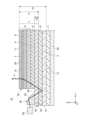
- FIG. 1 is a schematic cross-sectional view of a laminated film according to an embodiment.
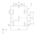
- FIG. 2 is a schematic plan view of a light extraction layer according to an embodiment. 3 is a cross-sectional view taken along line III-III in FIG. 2.
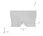
- FIG. 2 is a schematic cross-sectional view of a light extraction portion according to an embodiment. 3 is a schematic cross-sectional view of a light extraction portion according to the first embodiment.
- FIG. FIG. 2 is a schematic plan view of a light extraction unit according to the first embodiment.
- a Cartesian coordinate system having an X-axis, Y-axis, and Z-axis is used to represent directions.
- the X-axis, Y-axis, and Z-axis are approximately perpendicular to one another.
- the direction in which the X-axis arrow points is expressed as the +X direction or +X side, and the direction opposite the +X direction is expressed as the -X direction or -X side.
- the direction in which the Y-axis arrow points is expressed as the +Y direction or +Y side, and the direction opposite the +Y direction is expressed as the -Y direction or -Y side.
- the direction in which the Z-axis arrow points is expressed as the +Z direction or +Z side, and the direction opposite the +Z direction is expressed as the -Z direction or -Z side.
- the Z direction along the Z axis indicates the stacking direction of each layer constituting the laminate film according to the embodiment.
- planar view refers to viewing an object from the Z direction.
- the +Z direction is referred to as "up.”
- the adherend on which the laminate film according to the embodiment is placed is located in the -Z direction when viewed from the laminate film.
- these directional expressions do not limit the directions of the embodiment.
- thickness refers to the length of an object in the Z direction, i.e., the stacking direction of each layer.
- the cross-sectional view shows a cross section parallel to the YZ plane of the laminate film according to the embodiment.
- FIG. 1 is a cross-sectional view showing an example of a laminated film 10 according to the first embodiment.
- the laminated film 10 has a light guide member 1 that guides light L incident from a light source 50, and a low refractive index layer 2 that is arranged on one side of the light guide member 1 and has a refractive index of 1.30 or less.
- the low refractive index layer 2 can be arranged on one side of the light guide member 1 via a third adhesive layer 9.
- the light guide member 1 includes a light extraction portion 31 that can extract the light L guided by the light guide member 1.
- the thickness t1 of the light guide member 1 is 1000 ⁇ m or less.
- the thickness t1 of the light guide member 1 is preferably 800 ⁇ m or less, 700 ⁇ m or less, 600 ⁇ m or less, 500 ⁇ m or less, 400 ⁇ m or less, or 300 ⁇ m or less.
- the lower limit is not particularly limited, but is 100 ⁇ m or more and 200 ⁇ m or more.
- the total thickness t2 from the first surface 11, which is the surface of the light guide member 1 on the side opposite to the side where the low refractive index layer 2 is disposed, to the second surface 12, which is the surface of the low refractive index layer 2 on the side opposite to the light guide member 1, is 1500 ⁇ m or less.
- the total thickness t2 is preferably 1000 ⁇ m or less, 800 ⁇ m or less, 700 ⁇ m or less, 600 ⁇ m or less, 500 ⁇ m or less, 400 ⁇ m or less, or 300 ⁇ m or less.
- the lower limit is not particularly limited, but is preferably 100 ⁇ m or more, or 200 ⁇ m or more.
- the laminated film 10 can guide the light L incident from the light source 50 using the light guide member 1, and can extract the light L from inside the light guide member 1 to the outside using the light extraction section 31.
- the laminated film 10 can illuminate the space in which the laminated film 10 is placed using the light L extracted from the light guide member 1.
- the light source 50 is, for example, an LED (Light Emitting Diode) light source.
- the laminate film 10 can be made less noticeable and less noticeable.
- a laminate film 10 with high designability can be provided.
- the laminate film 10 can enhance the designability of the adherend 20 on which the laminate film 10 is placed.
- the laminate film 10 can be made flexible. By making the laminate film 10 flexible, it is possible to reduce poor placement, such as the occurrence of wrinkles or air getting between the laminate film 10 and the adherend 20 when placing the laminate film 10 on the adherend 20. Unlike the conventional light guide plate, which is a plate-shaped member, the laminate film 10 can be handled in a roll with the light guide member integrated. In other words, in this embodiment, a roll of laminate film 10 with high designability can be provided.
- the reaching light L may be scattered by the adherend 20, causing the luminance of the illumination light to attenuate, or the reaching light may be absorbed by the adherend 20, causing the hue of the illumination light to change.
- the adherend 20 is float glass
- the float glass absorbs light with a wavelength corresponding to red among the light L that reaches the float glass, causing the illumination light to appear blue.
- the laminated film 10 can totally reflect the light L guided by the light-guiding member 1 at the low refractive index layer 2, thereby reducing the light L from reaching the adherend 20. This can reduce the luminance attenuation and hue change of the illumination light caused by the laminated film 10.
- the laminated film 10 can be placed on an adherend 20.
- the adherend 20 include glass, windows, walls, floors, and ceilings.
- the laminated film 10 is placed by being attached to the surface of the adherend 20.
- the laminate film 10 can be made of resin. By being made of resin, the laminate film 10 has high flexibility and can be handled in various forms. For example, before being placed on the adherend 20, the laminate film 10 is provided with a release liner on the first adhesive layer 7 and can be handled in the form of a long roll, making it easy to handle. However, the laminate film 10 does not necessarily have to be made of resin, and at least a portion of it may be made of glass or the like.
- the laminated film 10 can have a first adhesive layer 7 arranged on the side of the low refractive index layer 2 opposite the light-guiding member 1. By having the first adhesive layer 7, the laminated film 10 can fix the light-guiding member 1, the third adhesive layer 9, and the low refractive index layer 2 onto the adherend 20.
- the light-guiding member 1 can have a light extraction layer 3 including a light extraction portion 31, and a transmissive layer 4 that transmits the light L incident from the light source 50.
- the light-guiding member 1 can guide the light L incident from the light source 50 and extract the light L from the inside of the light-guiding member 1 to the outside.
- the thickness t3 of the transmissive layer 4 can be set to 30 ⁇ m or more. By setting the thickness t3 of the transmissive layer 4 to 30 ⁇ m or more, the incidence efficiency of the light L from the light source 50 entering the laminated film 10 can be increased.
- the light extraction sections 31 may be multiple internal spaces provided in the light extraction layer 3. By having the light extraction sections 31 be multiple internal spaces provided in the light extraction layer 3, the laminated film 10 can extract highly directional light L from the inside of the light-guiding member 1 to the outside.
- the laminated film 10 can have a second adhesive layer 8 disposed between the transparent layer 4 and the light extraction layer 3.
- the ratio of the thickness of the second adhesive layer 8 to the thickness of the light guide member 1 can be 10% or more, preferably 15% or more and 20%, with no particular upper limit, for example 50% or less, 40% or less.
- the end 3a of the light extraction layer 3 may be located inside the end 4a of the transmissive layer 4.
- the distance between the end 3a of the light extraction layer 3 and the end 4a of the transmissive layer 4 is 1 mm or more and 100 mm or less.
- the inside in plan view means the side closer to the center of the laminated film 10 when the laminated film 10 is viewed in plan.
- the end 3a of the light extraction layer 3 is located inside the end 4a of the transmissive layer 4, so that a member for allowing the light L from the light source 50 to enter the laminated film 10 can be arranged in the region 4b of the transmissive layer 4 where the light extraction layer 3 and the transmissive layer 4 do not overlap, and the efficiency of incidence of the light L from the light source 50 to the laminated film 10 can be increased.
- the region 4b is defined by the end 3a of the light extraction layer 3 and the end 4a of the transmissive layer 4.
- the laminated film 10 can have a light entrance member 40 that is disposed in an area 4b of the transparent layer 4 where the light extraction layer 3 and the transparent layer 4 do not overlap in a planar view, and that allows light L from the light source 50 to enter the laminated film 10. With this configuration, the laminated film 10 makes it easier for light L to enter the laminated film 10 from the light source 50.
- the light extraction layer 3 can include a light extraction portion forming layer 30 in which a light extraction portion 31 is formed, a substrate 5, and a fourth adhesive layer 6 that is disposed between the light extraction portion forming layer 30 and the substrate 5 and adhesively bonds the light extraction portion forming layer 30 and the substrate 5.
- the laminated film 10 can have a third adhesive layer 9 that is disposed between the transparent layer 4 and the low refractive index layer 2 and adhesively bonds the transparent layer 4 and the low refractive index layer 2.
- the refractive index of the low refractive index layer 2 is preferably 1.25 or less, more preferably 1.20 or less, and even more preferably 1.15 or less.
- the low refractive index layer 2 is preferably a solid, and the refractive index is preferably 1.05 or more.
- the difference between the refractive index of the transparent layer 4 and the refractive index of the low refractive index layer 2 is preferably 0.20 or more, more preferably 0.23 or more, and even more preferably 0.25 or more.
- the low refractive index layer 2 having a refractive index of 1.25 or less can be formed, for example, using a porous material.
- the thickness of the low refractive index layer 2 is, for example, 0.3 ⁇ m or more and 5.0 ⁇ m or less.
- the low refractive index layer 2 is used by being coated on a substrate film (not shown), such as an acrylic film.
- the low refractive index layer 2 and the substrate film (not shown) are arranged in the order of the first adhesive layer 7, the low refractive index layer 2, the substrate film (not shown), and the third adhesive layer 9.
- the thickness of the substrate film (not shown) is, for example, 5 ⁇ m or more and 100 ⁇ m or less, preferably 50 ⁇ m or less.
- the porosity is preferably 35 volume % or more, more preferably 38 volume % or more, and particularly preferably 40 volume % or more. Within this range, a low refractive index layer with a particularly low refractive index can be formed.
- the upper limit of the porosity of the low refractive index layer is, for example, 90 volume % or less, and preferably 75 volume % or less. Within this range, a low refractive index layer with excellent strength can be formed.
- the porosity here is a value calculated from the refractive index measured with an ellipsometer using the Lorentz-Lorenz's formula.
- the low refractive index layer 2 for example, a low refractive index layer having voids disclosed in WO 2019/146628 can be used.
- the low refractive index layer having voids includes silica particles, silica particles having micropores, approximately spherical particles such as hollow silica nanoparticles, fibrous particles such as cellulose nanofibers, alumina nanofibers, and silica nanofibers, and flat particles such as nanoclay composed of bentonite.
- the low refractive index layer having voids is a porous body formed by direct chemical bonding of particles (e.g., microporous particles).
- the particles constituting the low refractive index layer having voids may be bonded to each other via a small amount (e.g., equal to or less than the mass of the particles) of a binder component.
- the porosity and refractive index of the low refractive index layer can be adjusted by the particle size, particle size distribution, etc. of the particles constituting the low refractive index layer.
- Methods for obtaining a low refractive index layer having voids include, for example, the methods described in JP 2010-189212 A, JP 2008-040171 A, JP 2006-011175 A, WO 2004/113966 A, and references thereto.
- the disclosures of JP 2010-189212 A, JP 2008-040171 A, JP 2006-011175 A, and WO 2004/113966 are all incorporated herein by reference.
- a porous silica body can be suitably used as a low refractive index layer having voids.
- a porous silica body can be produced, for example, by the following methods.
- Silicon compounds A method of hydrolyzing and polycondensing at least one of hydrolyzable silanes and silsesquioxanes, and at least one of their partial hydrolyzates and dehydrated condensates, a method of using at least one of porous particles and hollow fine particles, a method of producing an aerogel layer by utilizing the springback phenomenon, a method of using a crushed gel in which a gel-like silicon compound obtained by the sol-gel method is crushed and the resulting crushed body, that is, microporous particles, are chemically bonded together with a catalyst or the like, and so forth.
- the low refractive index layer 2 is not limited to a porous silica body.
- the manufacturing method of the low refractive index layer 2 is not limited to the manufacturing method exemplified above, and any manufacturing method may be used.
- the porous layer is not limited to a porous silica body, and the manufacturing method is not limited to the manufacturing method exemplified above, and any manufacturing method may be used.
- Silsesquioxane is a silicon compound having a basic structural unit of ( RSiO1.5 , R is a hydrocarbon group), and strictly speaking is different from silica having a basic structural unit of SiO2 .
- a porous body containing silsesquioxane as a basic structural unit is also referred to as a silica porous body or a silica-based porous body.
- the porous silica body may be composed of microporous particles of a gel-like silicon compound bonded together.
- the microporous particles of the gel-like silicon compound include pulverized bodies of the gel-like silicon compound.
- the porous silica body may be formed, for example, by applying a coating liquid containing the pulverized bodies of the gel-like silicon compound to a substrate.
- the pulverized bodies of the gel-like silicon compound may be chemically bonded (e.g., siloxane bonds) by, for example, the action of a catalyst, exposure to light, heating, etc.
- FIG. 3 is a plan view that shows the light extraction layer 3.
- Figure 3 is a cross-sectional view that shows the light extraction layer 3.
- Figure 4 is a cross-sectional view that shows the light extraction portion 31.
- the light extraction section 31 included in the light extraction layer 3 may be a plurality of internal spaces provided in the light extraction layer 3. Each of the plurality of internal spaces forms an interface that directs light to the +Z side by total internal reflection.
- the internal space is also called a cavity.
- the internal space has a triangular cross-sectional shape (perpendicular to the X direction, parallel to the YZ plane) with an apex angle on the +Z side, and directs the light L propagating in the light-guiding member 1 to the +Y side to the +Z side.
- the light L directed to the +Z side by the internal space is emitted from the laminated film 10.
- the cross-sectional shape of the internal space is not limited to this, and may be a trapezoid or the like as long as it has an interface that directs the light L propagating in the +Y direction to the +Z side.
- the direction of light emission can be changed by changing the cross-sectional shape of the internal space (for example, the direction of the apex angle of the triangle).
- the laminated film 10 can extract the light L guided by the light-guiding member 1 by the light extraction section 31 and control the light distribution of the extracted light L, so that the visible light transmittance can be 60% or more and the haze value can be less than 10%.
- the light extraction section 31 is typically a void section (air cavity) filled with air.
- the air cavity may be filled with a material having a refractive index lower than that of the light extraction section forming layer 30 instead of air.
- the light-guiding member 1 has a plurality of internal spaces, which are light extraction sections 31, arranged regularly or randomly along the main surface, i.e., a plane approximately parallel to the XY plane.
- the size of each internal space can be appropriately selected within a range that allows installation inside the light extraction section forming layer 30.
- the light-guiding layers disclosed in WO 2019/182091, WO 2011/124765, WO 2019/087118, and WO 2011/127187 can be used. The disclosures of these publications are incorporated herein by reference in their entirety.
- the light extraction layer 3 is produced, for example, by bonding a first film on which no pattern is formed and a second film on which the desired fine pattern is formed, using a lamination method or by bonding them with an adhesive (including a pressure-sensitive adhesive).
- the second film can be patterned using laser patterning, direct laser imaging, laser drilling, masked or maskless laser or electron beam irradiation. Individual properties can also be imparted by printing, inkjet printing, screen printing, etc. to change the material or refractive index value. Micro or nano dispensing, dosing, direct "writing", discrete laser sintering, micro-EDM (Electrical Discharge Machining), or micromachining, micromolding, imprinting, embossing, and the like can also be used.
- the multiple internal spaces that are the light extraction portion 31 preferably have an area ratio (occupancy rate) of 30% or less of the area of the light extraction portion forming layer 30 in a plan view.
- the occupancy rate of the internal spaces may be uniform, or may increase with increasing distance from the light source 50 so that the brightness does not decrease even if the distance from the light source 50 increases. It is preferable that the occupancy rate of the internal spaces is uniform.
- the occupancy rate of the internal spaces is 1% or more and 30% or less, with the upper limit being more preferably 25% or less, and in order to obtain a high visible light transmittance, it is preferable that it is 10% or less, and more preferably 5% or less.
- the above-mentioned characteristics of the light extraction portion 31 are not limited to the multiple internal spaces formed in the light extraction portion forming layer 30 exemplified here, but are common to various light distribution control structures.
- a light distribution control structure formed by multiple internal spaces for example, the light distribution structure described in International Publication No. 2019/087118 can be used.
- the light extraction portion 31 is not limited to a plurality of internal spaces, and may be a plurality of prisms arranged in the light extraction portion forming layer 30.
- the light extraction portion forming layer 30 may be a prism sheet containing a plurality of prisms therein.
- a plurality of convex portions (prism portions) may be formed directly on the surface of the light extraction portion forming layer 30.
- the refractive index of the light extraction portion forming layer 30 is preferably approximately equal to the refractive index of each of the base material 5 and the fourth adhesive layer 6, and the difference (absolute value) between the refractive indices is preferably 0.15 or less, and more preferably 0.1 or less.
- a light distribution control structure in which the light extraction section 31 is a plurality of internal spaces has a higher light utilization efficiency than a light distribution control structure such as a prism sheet.
- the light distribution can be controlled by adjusting the cross-sectional shape (for example, the angles ⁇ a and ⁇ b of the inclined surfaces in FIG. 4), size, arrangement density, distribution, etc. of the internal space.
- the visible light transmittance and haze value of the laminated film 10 can be controlled by adjusting the cross-sectional shape, size, arrangement density, and distribution of the multiple internal spaces of the light extraction section 31.
- the visible light transmittance of the laminated film 10 is 60% or more, and preferably 65% or more, 70% or more, 75% or more, or 80% or more.
- the haze value of the laminated film 10 is less than 10%, and preferably less than 9%, less than 8%, less than 7%, less than 6%, less than 5%, less than 4%, or less than 3%.
- the haze value can be measured using a haze meter.
- the size and density of the internal space affect the haze value.
- the size of the internal space (length M, width W: see Figures 2 to 4) is, for example, preferably 10 ⁇ m or more and 500 ⁇ m or less in length M, and 1 ⁇ m or more and 100 ⁇ m or less in width W. From the viewpoint of the light extraction efficiency of the light extraction layer 3, it is preferable that the height H is 1 ⁇ m or more and 100 ⁇ m or less. It is preferable that the multiple internal spaces are distributed discretely and uniformly, and for example, as shown in Figure 2, it is preferable to arrange them periodically.
- the pitch Px is, for example, preferably 10 ⁇ m or more and 500 ⁇ m or less
- the pitch Py is, for example, preferably 10 ⁇ m or more and 500 ⁇ m or less.
- the interval E in Figure 2 is the interval between the multiple internal spaces in the X direction.
- the interval D in Figure 2 is the interval between the multiple internal spaces in the Y direction.
- the transmissive layer 4 can be formed from a film having flat surfaces.
- the material used for the transmissive layer 4 is preferably one having a low light absorption coefficient.
- the material used for the transmissive layer 4 can be an acrylic film such as PMMA (Poly Methyl Methylate), a cycloolefin film such as COP (Cyclo Olefin Polymer), a polyethylene film such as PET (Polyethylene Terephthalate), a polycarbonate film, or the like.
- the thickness t3 of the transmissive layer 4 is preferably 30 ⁇ m or more, more preferably 40 ⁇ m or more, and even more preferably 60 ⁇ m or more or 100 ⁇ m or more.
- the thickness t3 of the transmissive layer 4 is preferably 800 ⁇ m or less, more preferably 600 ⁇ m or less, even more preferably 500 ⁇ m or less or less than 500 ⁇ m, and particularly preferably 400 ⁇ m or less.
- the refractive index of the transmissive layer 4 is preferably, for example, 1.45 or more and 1.60 or less. It is preferable that the same film as the transmissive layer 4 is used for the substrate film on which the low refractive index layer 2 is applied, the light extraction layer 3, and the substrate film to be bonded to the light extraction layer 3.
- At least one of an acrylic, polyester, or other pressure-sensitive adhesive and adhesive can be appropriately selected for each of the first tacky-adhesive layer 7, the second tacky-adhesive layer 8, the third tacky-adhesive layer 9, and the fourth tacky-adhesive layer 6.
- the refractive index of each of the first tacky-adhesive layer 7, the second tacky-adhesive layer 8, the third tacky-adhesive layer 9, and the fourth tacky-adhesive layer 6 is preferably approximately the same as that of the transparent layer 4, and is preferably, for example, 1.45 or more and 1.60 or less.
- the light incidence member 40 has a bottom surface 41 for laminating on a surface such as the upper surface of the transmissive layer 4, a light incidence surface 42 for receiving the light L from the light source 50, and an inclined surface 43 for reflecting the light L received from the light source 50 and directing it to the transmissive layer 4 side.
- the inclined surface 43 can control the direction of the light received on the inclined surface 43 at an angle less than the critical angle.
- the inclined surface 43 may be a flat surface or a curved surface.
- the curved surface of the inclined surface 43 may be a part of a spherical surface or a part of an aspherical surface. Examples of the aspherical surface include a parabolic surface.
- the light incidence member 40 has a tapered shape in which the thickness becomes thinner as it moves away from the light source 50.
- the laminated film 10 may have multiple light entrance members 40, or may have one light entrance member 40 that has a length that allows light from each of the multiple light sources 50 to enter in the direction in which the multiple light sources 50 are arranged.
- optical incoupling element disclosed in WO 2022/030544 can be used for the light input member 40.
- the entire disclosure of WO 2022/030544 is incorporated herein by reference.
- the light incidence member 40 may be any member capable of controlling the reflection direction of light L incident at an angle less than the critical angle, and may be, for example, a diffraction grating or a directional layer including an optical cavity.
- the directional layer may be formed, for example, by laminating a film on which an air cavity pattern is formed to another film.
- the directional layer may be, for example, the "optical incoupling tape" disclosed in WO 2022/030543. The entire disclosure of WO 2022/030543 is incorporated herein by reference.
- the gelled compound obtained by the above heat aging was crushed into granules of several mm to several cm in size, and isopropyl alcohol (IPA) was added in an amount four times the amount of gel. After lightly stirring, the mixture was left to stand at room temperature for six hours, and the solvent and catalyst in the gel were decanted. The same decantation process was repeated three times to complete the solvent replacement.
- IPA isopropyl alcohol
- the gel-like compound obtained by solvent replacement was subjected to high-pressure media-less grinding (homogenizer (product name UH-50, manufactured by SMT Corporation)) to produce a sol liquid.
- high-pressure media-less grinding homogenizer (product name UH-50, manufactured by SMT Corporation)
- the volume average particle size which indicates the particle size variation of the sol liquid at this time, was confirmed using a dynamic light scattering Nanotrack particle size analyzer (manufactured by Nikkiso Co., Ltd., product name UPA-EX150 model) and was found to be 0.50 ⁇ m or more and 0.70 ⁇ m or less.
- a 1.5 wt% isopropyl alcohol solution of a photobase generating catalyst (Wako Pure Chemical Industries, Ltd.: product name WPBG266) was prepared and added at 0.031 parts to 0.75 parts of the sol particle liquid, and 0.018 parts of 5% bis(trimethoxysilyl)ethane was added to prepare a coating liquid.
- the coating liquid for forming the low refractive index layer was applied to a substrate film (PMMA: Poly Methyl Methylacrylate, thickness 30 ⁇ m) so that the thickness after curing would be 1 ⁇ m, and the coating was heated and dried to cure, obtaining a low refractive index layer (thickness 31 ⁇ m) with a substrate film.
- the refractive index of the obtained low refractive index layer was 1.16.
- FIG. 5 is a cross-sectional view showing an example of a light extraction portion in the example.
- FIG. 6 is a plan view showing an example of a light extraction portion in the example.
- the height (depth) H of the recess as the light extraction section was 10 ⁇ m
- the width W was 10.5 ⁇ m
- the inclination angle ⁇ c of the first inclined surface ISa was 49°
- the inclination angle ⁇ d of the second inclined surface ISb was 80°.
- the pitch Py of the recess in the direction in which the light is guided e.g., the Y direction
- the pitch Px in the direction perpendicular to the direction in which the light is guided e.g., the X direction
- Example 1 A fourth adhesive layer 6 (made of polyester resin, thickness 7 ⁇ m) was placed on the main surface on which the recesses were formed in the light extraction layer 3 produced in Production Example 4, and a substrate 5 (made of PMMA, thickness 30 ⁇ m) was laminated through the fourth adhesive layer 6 to obtain a light extraction layer 3 (thickness 165 ⁇ m). Further, a transmission layer 4 was laminated (made of PMMA, thickness 130 ⁇ m) through a second adhesive layer 8 (manufactured by Nitto Denko Corporation CS9864, thickness 100 ⁇ m) on the opposite side of the fourth adhesive layer 6 of the substrate 5, to obtain a light guide member 1 (thickness 395 ⁇ m).
- the substrate film side of the low refractive index layer 2 with the substrate film produced in Production Example 1 was laminated through a third adhesive layer 9 (made of acrylic resin, thickness 10 ⁇ m) on the opposite side of the second adhesive layer 8 of the transmission layer 4 to obtain a laminated film 10 (thickness 456 ⁇ m). Furthermore, a first adhesive layer 7 (made of acrylic resin, thickness 10 ⁇ m) was arranged on the opposite side of the low refractive index layer 2 with the base film (30 ⁇ m), and the laminate film 10 was arranged on highly transmittant glass (manufactured by Nippon Sheet Glass Co., Ltd., thickness 5 mm) as the adherend 20 via the first adhesive layer 7.
- a third adhesive layer 9 made of acrylic resin, thickness 10 ⁇ m
- a first adhesive layer 7 made of acrylic resin, thickness 10 ⁇ m
- highly transmittant glass manufactured by Nippon Sheet Glass Co., Ltd., thickness 5 mm
- a laminated film 10 was produced having a light extraction layer 3, a fourth adhesive layer 6, a substrate 5, a second adhesive layer 8, a transparent layer 4, a third adhesive layer 9, a low refractive index layer 2 with a substrate film, and a first adhesive layer 7.
- the laminated film 10 was formed so that the end 3a of the light extraction layer 3 was located inside the end 4a of the transmissive layer 4.
- a light incidence member 40 that allows light from the light source 50 to enter the laminated film 10 was placed in an area 4b of the transmissive layer 4 where the light extraction layer 3 and the transmissive layer 4 do not overlap in a plan view.
- the length of the area 4b in the Y direction was set to 50 mm.
- the light incidence member 40 was placed on the transmissive layer 4 by adhesively adhering it to the transmissive layer 4 via an adhesive layer.
- the light source 50 was also placed so that light could enter the laminated film 10 through the light incidence member 40.
- the laminated film 10 placed on the adherend 20 was evaluated as described above.
- Example 2 The procedure was the same as in Example 1, except that the low refractive index layer with the base film prepared in Production Example 2 was used instead of Production Example 1.
- Example 3 The embodiment was the same as the first embodiment, except that a light source 50 was disposed at the end 4 a of the transmissive layer 4 instead of the light incident member 40 .
- Example 4 The same procedure as in Example 1 was followed except that the second adhesive layer 8 was replaced with another second adhesive layer (CS9862 manufactured by Nitto Denko Corporation, thickness 50 ⁇ m), and the light extraction portion forming layer 30 was replaced with a thinner light extraction portion forming layer (thickness 60 ⁇ m).
- CS9862 manufactured by Nitto Denko Corporation, thickness 50 ⁇ m
- a thinner light extraction portion forming layer thickness 60 ⁇ m
- Example 5 The same procedure as in Example 1 was followed except that a thinner transmissive layer (thickness: 30 ⁇ m) was used instead of the transmissive layer 4 .
- Example 6 The same as in Example 1 was used, except that the transmissive layer 4 was replaced with a thinner transmissive layer (thickness 40 ⁇ m), and instead of the light input member 40, a light source 50 was placed at the end of a transmissive layer thinner than the transmissive layer 4.
- a thinner transmissive layer thickness 40 ⁇ m
- Example 2 The same procedure as in Example 1 was repeated except that the low refractive index layer 2 with the base film and the first adhesive layer 7 were not provided.
- Example 3 The same procedure as in Example 1 was repeated, except that float glass (manufactured by Nippon Sheet Glass Co., Ltd., thickness 5 mm) was used instead of the high transmittance glass, and the low refractive index layer 2 with the substrate film and the first adhesive layer 7 were not provided.
- float glass manufactured by Nippon Sheet Glass Co., Ltd., thickness 5 mm
- Example 4 The same as in Example 1 was used except that a thicker transmissive layer (thickness 2000 ⁇ m) was used instead of the transmissive layer 4, and a light source 50 was disposed at the end of a transmissive layer thicker than the transmissive layer 4 instead of the light input member 40.
- Table 1 shows a list of the conditions and evaluation results for each of Examples 1 to 6 and Comparative Examples 1 to 3. In the "Flexibility/Presence” section in Table 1, if both flexibility and presence were “ ⁇ ”, it was marked “ ⁇ ”, and if at least one of flexibility and presence was “ ⁇ ”, it was marked " ⁇ ".
- the laminate film 10 can also have an adherend 20 arranged on the side of the low refractive index layer 2 opposite to the light guide member 1. By having the laminate film 10 have the adherend 20, it is possible to provide the laminate film 10 with the adherend 20 having excellent design properties.
- the adherend 20 is not limited to glass, but may be an electronic substrate such as a liquid crystal cell, or a non-light-transmitting member such as a ceiling, a wall, or a floor.
- the light extraction layer 3 is not limited to extracting light L to the side opposite to the side on which the adherend 20 is located, but may extract light L to the side on which the adherend 20 is located. In this case, if the adherend 20 has high light transmittance, the extracted light L may transmit through the adherend 20, or if the adherend 20 has low light transmittance, the adherend 20 may reflect light.
- the light extraction layer 3 may be disposed between the transmission layer 4 and the low refractive index layer 2.
- a pattern layer for improving luminance uniformity may be provided between the transparent layer 4 and the light extraction layer 3.
- the optical coupling layer disclosed in WO 2022/025067 can be used.
- the entire disclosure of WO 2022/025067 is incorporated herein by reference.
- the pattern layer is formed by a first portion having a lower refractive index than the transparent layer 4 and a second portion having a higher refractive index than the first portion.
- the first portion may be a low refractive index layer such as the low refractive index layer 2, or may be an air cavity.
- the second portion may be formed by a tacky adhesive layer, or may be formed by filling the void portion of the low refractive index layer with a material such as a tacky adhesive.
- the thickness of the light guide member 1 is preferably 1000 ⁇ m or less, more preferably 800 ⁇ m or less, 700 ⁇ m or less, 600 ⁇ m or less, 500 ⁇ m or less, 400 ⁇ m or less, or 300 ⁇ m or less.
- a substrate film may be further disposed on the side of the light extraction layer 3 opposite to the side on which the transmission layer 4 is located.
- This substrate film may be a hard coat layer or an anti-reflection layer.
- a low refractive index layer may be present between the light extraction layer 3 and the substrate film.
- the thickness of the light guide member 1 is preferably 1000 ⁇ m or less, and more preferably 800 ⁇ m or less, 700 ⁇ m or less, 600 ⁇ m or less, 500 ⁇ m or less, 400 ⁇ m or less, or 300 ⁇ m or less.
- the transmissive layer 4 and the light extraction layer 3 are not limited to being separate films, and may be integrated with each other.
- a transmissive layer 4 having patterned recesses formed therein can function both as the transmissive layer 4 and the light extraction layer 3.
- the light extraction layer 3 does not necessarily have to have a substrate 5.
- the light guide member 1 does not necessarily have to have a second adhesive layer 8.
- the low refractive index layer 2 is applied to a base film (not shown), and that the first adhesive layer 7, the low refractive index layer 2, the base film (not shown), and the third adhesive layer 9 are arranged in that order.
- the order of the low refractive index layer 2 and the base film (not shown) may be reversed, and the base film (not shown) may be omitted.
- the low refractive index layer 2 may be applied directly to the light-guiding member 1, i.e., the transmissive layer 4, and the third adhesive layer 9 and the base film (not shown) may be omitted.
- a surface protection film having a substrate and an adhesive may be appropriately attached to the surface of the light guiding member or the low refractive index layer.
- a release liner may be attached to the surface of the first adhesive layer.
- the laminated film according to the embodiment has high designability, and can be combined with a light source and placed on architectural components such as glass, windows, walls, floors, and ceilings to illuminate the interior or exterior space of a building while improving the design of the architectural components. Also, when placed on a partition, it can be used as an interior divider or to conceal a desired space while improving the design of the partition. Also, when placed on the glass substrate of a display device such as a liquid crystal panel or an organic EL (Electro Luminescence) display panel, it can be used for backlight illumination in the display device while improving the design of the display device. Furthermore, the laminated film according to the embodiment can provide new uses other than those mentioned above.
- a surface lighting device can also be configured using the laminate film of this embodiment and a light source disposed near the end of the laminate film.
- Light from the light source can enter the interior of the laminate film from an end face of the laminate film along the lamination direction, or from a face that intersects with the end face (the main face of the laminate film).
- Light from the light source can enter the interior of the laminate film directly without passing through a light entrance member, or can enter the interior of the laminate film via a light entrance member.
- a laminated film comprising: a light-guiding member that guides light incident from a light source; and a low-refractive index layer that is disposed on one side of the light-guiding member and has a refractive index of 1.30 or less, wherein the light-guiding member includes a light extraction portion that is capable of extracting light guided by the light-guiding member, the light-guiding member has a thickness of 1000 ⁇ m or less, and an overall thickness from a first surface that is a surface of the light-guiding member on the side opposite to the side on which the low-refractive index layer is disposed to a second surface that is a surface of the low-refractive index layer on the side opposite to the light-guiding member is 1500 ⁇ m or less.
- the laminate film according to ⁇ 1> further comprising a first adhesive layer disposed on the low refractive index layer on an opposite side to the light guide member.
- the light guide member is the laminate film according to any one of ⁇ 1> to ⁇ 3>, wherein the light guide member has a light extraction layer including the light extraction portion and a transmission layer that transmits light incident from the light source.
- the transmissive layer has a thickness of 30 ⁇ m or more.
- the light extraction portion is a plurality of internal spaces provided in the light extraction layer.
- ⁇ 6> The laminate film according to any one of ⁇ 3> to ⁇ 5>, further comprising a second adhesive layer disposed between the transmission layer and the light extraction layer, wherein a ratio of a thickness of the second adhesive layer to a thickness of the light guide member is 10% or more.
- ⁇ 7> The laminate film according to any one of ⁇ 3> to ⁇ 6>, wherein an end of the light extraction layer is located more inward than an end of the transmission layer in a plan view.
- ⁇ 8> The laminate film according to ⁇ 7>, further comprising a light entrance member arranged in a region of the transmissive layer where the light extraction layer and the transmissive layer do not overlap in a planar view, and which allows light from the light source to enter.
- ⁇ 9> The laminate film according to any one of ⁇ 1> to ⁇ 8>, further comprising an adherend arranged on a side of the low refractive index layer opposite to the light guide member.
- Light guide member 11 First surface 12 Second surface 2 Low refractive index layer 3 Light extraction layer 30 Light extraction portion forming layer 31 Light extraction portion 3a End 4 Transmitting layer 4a End 4b Region 5 Substrate 6 Fourth adhesive layer 7 First adhesive layer 8 Second adhesive layer 9 Third adhesive layer 10 Laminated film 20 Adherend 40 Light incidence member 41 Bottom surface 42 Light incidence surface 43 Inclined surface 50 Light source L Light t1 Thickness t2 of light guide member Total thickness t3 of laminated film Thickness D of transmissive layer Spacing E between multiple internal spaces in Y direction Spacing ISa between multiple internal spaces in X direction First inclined surface ISb Second inclined surface M Length Px Pitch Py of multiple internal spaces in X direction Pitch H of multiple internal spaces in Y direction Height W Width ⁇ a, ⁇ b Angle ⁇ c, ⁇ d Inclined angle
Landscapes
- Physics & Mathematics (AREA)
- Engineering & Computer Science (AREA)
- Optics & Photonics (AREA)
- General Engineering & Computer Science (AREA)
- General Physics & Mathematics (AREA)
- Spectroscopy & Molecular Physics (AREA)
- Microelectronics & Electronic Packaging (AREA)
- Manufacturing & Machinery (AREA)
- Laminated Bodies (AREA)
- Planar Illumination Modules (AREA)
Abstract
Description
<実施形態に係る積層フィルム10の全体構成例>
図1は、第1実施形態に係る積層フィルム10の一例を模式的に示す断面図である。図1に示す例では、積層フィルム10は、光源50から入射される光Lを導光する導光部材1と、導光部材1の一方側に配置され、屈折率が1.30以下である低屈折率層2と、を有する。低屈折率層2は、導光部材1の一方側に第3粘接着層9を介して配置されることができる。導光部材1は、導光部材1により導光される光Lを抽出可能な光抽出部31を含む。導光部材1の厚みt1は、1000μm以下である。導光部材1の厚みt1は、800μm以下、700μm以下、600μm以下、500μm以下、400μm以下、300μm以下であることが好ましい。下限は特に限定されないが、100μm以上、200μm以上である。低屈折率層2が配置された側とは反対側における導光部材1の表面である第1面11から、導光部材1とは反対側における低屈折率層2の表面である第2面12までの全体厚みt2は、1500μm以下である。全体厚みt2は、1000μm以下、800μm以下、700μm以下、600μm以下、500μm以下、400μm以下、300μm以下であることが好ましい。下限は特に限定されないが、100μm以上、200μm以上である。
低屈折率層2の屈折率は、例えば1.25以下であることが好ましく、1.20以下であることがより好ましく、1.15以下がさらに好ましい。低屈折率層2は固体であることが好ましく、屈折率は、例えば1.05以上であることが好ましい。透過層4の屈折率と低屈折率層2の屈折率との差は、好ましくは0.20以上であり、より好ましくは0.23以上であり、さらに好ましくは0.25以上である。屈折率が1.25以下の低屈折率層2は、例えば多孔質材料を用いて形成され得る。低屈折率層2の厚みは、例えば、0.3μm以上5.0μm以下である。低屈折率層2は例えばアクリルフィルムなどの図示しない基材フィルムに塗工されて用いられる。低屈折率層2と図示しない基材フィルムは、第1粘接着層7、低屈折率層2、図示しない基材フィルム、第3粘接着層9の順に配置される。図示しない基材フィルムの厚みは例えば5μm以上であり、100μm以下、好ましくは50μm以下である。
図1に加え、図2~4をさらに参照して、光抽出層3の構成の一例について説明する。図2は、光抽出層3を模式的に示す平面図である。図3は、光抽出層3を模式的に示す断面図である。図4は、光抽出部31を模式的に示す断面図である。
図1において、透過層4は、両面が平坦なフィルムから形成可能である。透過層4に用いる材料は、光吸収係数が低いものが好ましい。例えば、透過層4に用いる材料として、PMMA(Poly Methyl Methacrylate)等のアクリル系フィルム、COP(Cyclo Olefin Polymer)等のシクロオレフィン系フィルム、PET(Polyethylene Terephthalate)等のポリエチレン系フィルム、ポリカーボネート系フィルム等を使用できる。
第1粘接着層7、第2粘接着層8、第3粘接着層9および第4粘接着層6のそれぞれには、アクリル系、ポリエステル系等の粘着剤および接着剤の少なくとも一方を適宜選択できる。第1粘接着層7、第2粘接着層8、第3粘接着層9および第4粘接着層6それぞれの屈折率は、透過層4と同程度であることが好ましく、例えば1.45以上1.60以下が好ましい。
光入射部材40は、透過層4の上面等の面に積層するための底面41と、光源50からの光Lを入射させる光入射面42と、光源50から光入射部材40に入射された光Lを反射して透過層4側に導く傾斜面43と、を有する。傾斜面43は、臨界角未満の角度で傾斜面43に入射される光の方向を制御することができる。傾斜面43は、平面であってもよいし、曲面であってもよい。傾斜面43の曲面は、球面の一部であってもよいし、非球面の一部であってもよい。非球面には放物面等が挙げられる。図1に示す例では、光入射部材40は、光源50から遠ざかるほど厚みが薄くなるテーパ形状を有する。
以下、実施例および比較例について説明する。但し、本発明は、これらの例に何ら限定されない。
(屈折率の評価)
アクリルフィルムに低屈折率層を形成した後に、50mm×50mmのサイズにカットし、これを粘接着層でガラス板(厚み:3mm)の表面に貼り合わせた。ガラス板の裏面中央部(直径20mm程度)を黒マジックで塗りつぶして、ガラス板の裏面で光が反射されないサンプルを調製した。エリプソメーター(J.A.Woollam Japan社製:VASE)に、調整したサンプルをセットし、550nmの波長、入射角が50度以上80度以下の条件において屈折率を測定し、その平均値を屈折率とした。
実施例および比較例に係る積層フィルム内に光源50から光を入射させて、光抽出層側から光を取り出した。取り出された光について、目視で発光輝度を評価した。以下に、発光度合いの評価指標である「A」~[C]の定義を示す。
A:良好(輝度の減衰が小さい)。
B:やや良好(Aに比べ輝度が低いが、輝度の減衰が小さい)。
C:不良(A、Bに比べ輝度の減衰が大きく、導光される方向において光源50が位置する側と反対側に向かうほど暗くなる)。
実施例および比較例に係る積層フィルム内に光源50から光を入射させて、光抽出層側から光を抽出した。取り出された光の発光色を目視で評価した。以下に、発光色の評価指標である「〇」および[×]の定義を示す。
〇:白色。
×:輝度減衰し、導光される方向において、光源50が位置する側と反対側に向かうほど暗くなる(被着体が高透過ガラスである比較例1,2,4が該当する)。または、照明光が青く色づいて白色ではなくなる(被着体がフロートガラスである比較例3が該当する)。高透過ガラスは、入射した光の吸収や散乱が小さいガラスである。フロートガラスは、高透過ガラスと比較して入射した光の吸収や散乱が小さいガラスである。
実施例および比較例に係る積層フィルムから光が抽出された側から、被着体20に配置された該積層フィルムの存在感を目視で評価した。以下に、存在感の評価指標である「〇」および[×]の定義を示す。
〇:積層フィルムの存在感を感じない。
×:積層フィルムの存在感を感じる。
実施例および比較例に係る積層フィルムの可撓性を官能評価した。以下に可撓性の評価指標である「〇」および「×」の定義を示す。
〇:長尺の場合にロール巻き取りが可能なほど柔らかい。
×:長尺の場合にロール巻き取りが不可能なほど硬い。
(製造例1:基材フィルム付きの低屈折率層の作製)
ジメチルスルホキシド(DMSO:Dimethyl Sulfoxide)18部に、メチルトリメトキシシランを8部溶解させた。この混合液に、0 .01mol/Lのシュウ酸水溶液を4部添加し、室温で30分、撹拌を行うことで、メチルトリメトキシシランを加水分解させた。さらに、ジメチルスルホキシド65部、28%濃度のアンモニア水3部、および純水2部を添加した後、室温で15分撹拌、40℃で20時間の加熱エージングを行ない、ゲル状化合物を得た。
アルミナゾル液(4.9%濃度:川研ファインケミカル製)20部に、水13部添加し 、80℃で加熱後、NH3を3部添加した。さらに80℃で10時間加熱してゲル状化合物を得た。このゲル状化合物を製造例1のゲル状化合物に代えて用いた以外は、製造例1と同様の操作を行ない、基材フィルム付きの低屈折率層を得た。得られた低屈折率層の屈折率は1.24であった。
特開2008-299117号公報に記載の屈折率1.41の熱硬化型シリコーン材料(信越化学製OF-127)を用いた以外は、製造例1と同様の操作を行ない、基材フィルム付きの低屈折率層を得た。得られた低屈折率層の屈折率は1.41であった。
特表2013-524288号公報に記載の方法に従って、一方の主面に凹部を有する光抽出部形成層を作製した。具体的には、以下のとおりである。PMMAフィルム(厚み128μm)の表面をラッカー(三洋化成工業社製ファインキュアー RM-64)でコーティングし、当該ラッカーを含むフィルム表面上に所定の光学パターンをエンボス加工し、その後ラッカーを硬化させた。これにより、図5に示すような断面形状を有し、図6に示すような平面視形状を有する凹部を含む光抽出部形成層を作製した。ここで、図5は、実施例における光抽出部の一例を模式的に示す断面図である。図6は、実施例における光抽出部の一例を模式的に示す平面図である。
製造例4で作製した光抽出層3における凹部が形成されている主面に、第4粘接着層6(材質はポリエステル系樹脂、厚み7μm)を配置し、第4粘接着層6を介して基材5(材質はPMMA、厚み30μm)を積層し、光抽出層3を得た(厚み165μm)。さらに、基材5の第4粘接着層6とは反対側に第2粘接着層8(日東電工株式会社製CS9864、厚み100μm)を介して透過層4を積層し(材質はPMMA、厚み130μm)、導光部材1を得た(厚み395μm)。さらに、透過層4の第2粘接着層8とは反対側に第3粘接着層9(材質はアクリル系樹脂、厚み10μm)を介して製造例1で作製した基材フィルム付きの低屈折率層2の基材フィルム側を積層し、積層フィルム10を得た(厚み456μm)。さらに、基材フィルム(30μm)付きの低屈折率層2の基材フィルムとは反対側に第1粘接着層7(材質はアクリル系樹脂、厚み10μm)を配置し、第1粘接着層7を介して被着体20としての高透過ガラス(日本板硝子社製、厚み5mm)に積層フィルム10を配置した。
製造例1に代えて、製造例2で作製した基材フィルム付きの低屈折率層を用いたこと以外は、実施例1と同様とした。
光入射部材40に代えて、透過層4の端部4aに光源50を配置したこと以外は、実施例1と同様とした。
第2粘接着層8に代えて、別の第2粘接着層(日東電工株式会社製CS9862、厚み50μm)を用い、また光抽出部形成層30に変えて厚みが薄い光抽出部形成層(厚み60μm)にしたこと以外は、実施例1と同様とした。
透過層4に代えて、厚みが薄い透過層(厚み30μm)を用いたこと以外は、実施例1と同様とした。
透過層4に代えて、厚みが薄い透過層(厚み40μm)にし、光入射部材40に変えて、透過層4よりも厚みが薄い透過層の端部に光源50を配置したこと以外は、実施例1と同様とした。
製造例1に代えて、製造例3で作製した基材フィルム付きの低屈折率層を用いたこと以外は、実施例1と同様とした。
基材フィルム付きの低屈折率層2および第1粘接着層7を設けなかったこと以外は、実施例1と同様とした。
高透過ガラスに代えて、フロートガラス(日本板硝子社製、厚み5mm)を用いたこと、基材フィルム付きの低屈折率層2および第1粘接着層7を設けなかったこと以外は、実施例1と同様とした。
透過層4に代えて、厚みが厚い透過層(厚み2000μm)を用いたこと、光入射部材40に変えて、透過層4よりも厚みが厚い透過層の端部に光源50を配置したこと以外は、実施例1と同様とした。

積層フィルム10は、低屈折率層2における導光部材1とは反対側に配置される被着体20を有することもできる。積層フィルム10が被着体20を有することで、意匠性の高い被着体20付の積層フィルム10を提供できる。
<1> 光源から入射される光を導光する導光部材と、前記導光部材の一方側に配置され、屈折率が1.30以下である低屈折率層と、を有し、前記導光部材は、前記導光部材により導光される光を抽出可能な光抽出部を含み、前記導光部材の厚みは、1000μm以下であり、前記低屈折率層が配置された側とは反対側における前記導光部材の表面である第1面から、前記導光部材とは反対側における前記低屈折率層の表面である第2面までの全体厚みは、1500μm以下である、積層フィルムである。
<2> 前記低屈折率層における前記導光部材とは反対側に配置された第1粘接着層を有する、前記<1>に記載の積層フィルムである。
<3> 前記導光部材は、前記光抽出部を含む光抽出層と、前記光源から入射される光を透過する透過層と、を有する、前記<1>から前記<3>のいずれか1つに記載の積層フィルムである。
<4> 前記透過層の厚みは、30μm以上である、前記<3>に記載の積層フィルムである。
<5> 前記光抽出部は、前記光抽出層に設けられた複数の内部空間である、前記<3>または前記<4>に記載の積層フィルムである。
<6> 前記透過層と前記光抽出層との間に配置される第2粘接着層を有し、前記導光部材の厚みに対する前記第2粘接着層の厚みの割合は、10%以上である、前記<3>から前記<5>のいずれか1つに記載の積層フィルムである。
<7> 平面視において、前記光抽出層の端部は、前記透過層の端部よりも内側に位置している、前記<3>から前記<6>のいずれか1つに記載の積層フィルムである。
<8> 平面視において、前記光抽出層と前記透過層とが重ならない前記透過層の領域に配置され、前記光源からの光を入射させる光入射部材を有する、前記<7>に記載の積層フィルムである。
<9> 前記低屈折率層における前記導光部材とは反対側に配置される被着体を有する、前記<1>から前記<8>のいずれか1つに記載の積層フィルムである。
<10> 前記<1>から前記<9>のいずれか1つに記載の積層フィルムが巻き取られたロール。
11 第1面
12 第2面
2 低屈折率層
3 光抽出層
30 光抽出部形成層
31 光抽出部
3a 端部
4 透過層
4a 端部
4b 領域
5 基材
6 第4粘接着層
7 第1粘接着層
8 第2粘接着層
9 第3粘接着層
10 積層フィルム
20 被着体
40 光入射部材
41 底面
42 光入射面
43 傾斜面
50 光源
L 光
t1 導光部材の厚み
t2 積層フィルムの全体厚み
t3 透過層の厚み
D Y方向における複数の内部空間同士の間隔
E X方向における複数の内部空間同士の間隔
ISa 第1傾斜面
ISb 第2傾斜面
M 長さ
Px X方向における複数の内部空間のピッチ
Py Y方向における複数の内部空間のピッチ
H 高さ
W 幅
θa、θb 角度
θc、θd 傾斜角
Claims (10)
- 光源から入射される光を導光する導光部材と、
前記導光部材の一方側に配置され、屈折率が1.30以下である低屈折率層と、を有し、
前記導光部材は、前記導光部材により導光される光を抽出可能な光抽出部を含み、
前記導光部材の厚みは、1000μm以下であり、
前記低屈折率層が配置された側とは反対側における前記導光部材の表面である第1面から、前記導光部材とは反対側における前記低屈折率層の表面である第2面までの全体厚みは、1500μm以下である、積層フィルム。 - 前記低屈折率層における前記導光部材とは反対側に配置された第1粘接着層を有する、請求項1に記載の積層フィルム。
- 前記導光部材は、前記光抽出部を含む光抽出層と、前記光源から入射される光を透過する透過層と、を有する、請求項1または請求項2に記載の積層フィルム。
- 前記透過層の厚みは、30μm以上である、請求項3に記載の積層フィルム。
- 前記光抽出部は、前記光抽出層に設けられた複数の内部空間である、請求項3に記載の積層フィルム。
- 前記透過層と前記光抽出層との間に配置される第2粘接着層を有し、
前記導光部材の厚みに対する前記第2粘接着層の厚みの割合は、10%以上である、請求項3に記載の積層フィルム。 - 平面視において、前記光抽出層の端部は、前記透過層の端部よりも内側に位置している、請求項3に記載の積層フィルム。
- 平面視において、前記光抽出層と前記透過層とが重ならない前記透過層の領域に配置され、前記光源からの光を入射させる光入射部材を有する、請求項7に記載の積層フィルム。
- 前記低屈折率層における前記導光部材とは反対側に配置される被着体を有する、請求項1または請求項2に記載の積層フィルム。
- 請求項1または請求項2に記載の積層フィルムが巻き取られたロール。
Priority Applications (3)
| Application Number | Priority Date | Filing Date | Title |
|---|---|---|---|
| EP24819239.5A EP4722583A1 (en) | 2023-06-05 | 2024-05-29 | Multilayer film and roll |
| KR1020257037054A KR20260021595A (ko) | 2023-06-05 | 2024-05-29 | 적층 필름 및 롤 |
| CN202480036575.0A CN121311713A (zh) | 2023-06-05 | 2024-05-29 | 层叠膜以及卷 |
Applications Claiming Priority (2)
| Application Number | Priority Date | Filing Date | Title |
|---|---|---|---|
| JP2023-092333 | 2023-06-05 | ||
| JP2023092333A JP2024174483A (ja) | 2023-06-05 | 2023-06-05 | 積層フィルム、およびロール |
Publications (1)
| Publication Number | Publication Date |
|---|---|
| WO2024253008A1 true WO2024253008A1 (ja) | 2024-12-12 |
Family
ID=93795967
Family Applications (1)
| Application Number | Title | Priority Date | Filing Date |
|---|---|---|---|
| PCT/JP2024/019784 Ceased WO2024253008A1 (ja) | 2023-06-05 | 2024-05-29 | 積層フィルム、およびロール |
Country Status (6)
| Country | Link |
|---|---|
| EP (1) | EP4722583A1 (ja) |
| JP (1) | JP2024174483A (ja) |
| KR (1) | KR20260021595A (ja) |
| CN (1) | CN121311713A (ja) |
| TW (1) | TW202449437A (ja) |
| WO (1) | WO2024253008A1 (ja) |
Citations (14)
| Publication number | Priority date | Publication date | Assignee | Title |
|---|---|---|---|---|
| WO2004113966A1 (ja) | 2003-06-18 | 2004-12-29 | Asahi Kasei Kabushiki Kaisha | 反射防止膜 |
| JP2006011175A (ja) | 2004-06-28 | 2006-01-12 | Pentax Corp | 反射防止膜を有する光学素子及びその製造方法 |
| JP2008040171A (ja) | 2006-08-07 | 2008-02-21 | Pentax Corp | セルフクリーニング効果を有する反射防止膜を設けた光学素子及びその製造方法 |
| JP2008299117A (ja) | 2007-05-31 | 2008-12-11 | Fujikura Ltd | 表示装置 |
| JP2010189212A (ja) | 2009-02-17 | 2010-09-02 | Shinshu Univ | 多孔質シリカ膜およびその製造方法 |
| WO2011127187A1 (en) | 2010-04-06 | 2011-10-13 | Modilis Holding Llc | Internal cavity optics |
| WO2011124765A1 (en) | 2010-04-06 | 2011-10-13 | Kari Rinko | Laminate structure with embedded cavities and related method of manufacture |
| WO2019087118A1 (en) | 2017-11-01 | 2019-05-09 | Nitto Denko Corporation | Light distribution structure and element, related method and uses |
| WO2019146628A1 (ja) | 2018-01-26 | 2019-08-01 | 日東電工株式会社 | Led照明器具用フィルム、led照明器具 |
| WO2019182091A1 (ja) | 2018-03-22 | 2019-09-26 | 日東電工株式会社 | 光学デバイス |
| WO2022025067A1 (ja) | 2020-07-28 | 2022-02-03 | 日東電工株式会社 | 照明装置用導光部材、照明装置および建築部材 |
| WO2022030544A1 (en) | 2020-08-06 | 2022-02-10 | Nitto Denko Corporation | Light incoupling element, related method and uses |
| WO2022030543A1 (en) | 2020-08-06 | 2022-02-10 | Nitto Denko Corporation | Light incoupling tape, related method and uses |
| JP2023092333A (ja) | 2021-12-21 | 2023-07-03 | 株式会社デンソー | スイッチの駆動装置 |
-
2023
- 2023-06-05 JP JP2023092333A patent/JP2024174483A/ja active Pending
-
2024
- 2024-05-29 EP EP24819239.5A patent/EP4722583A1/en active Pending
- 2024-05-29 CN CN202480036575.0A patent/CN121311713A/zh active Pending
- 2024-05-29 KR KR1020257037054A patent/KR20260021595A/ko active Pending
- 2024-05-29 WO PCT/JP2024/019784 patent/WO2024253008A1/ja not_active Ceased
- 2024-05-31 TW TW113120216A patent/TW202449437A/zh unknown
Patent Citations (15)
| Publication number | Priority date | Publication date | Assignee | Title |
|---|---|---|---|---|
| WO2004113966A1 (ja) | 2003-06-18 | 2004-12-29 | Asahi Kasei Kabushiki Kaisha | 反射防止膜 |
| JP2006011175A (ja) | 2004-06-28 | 2006-01-12 | Pentax Corp | 反射防止膜を有する光学素子及びその製造方法 |
| JP2008040171A (ja) | 2006-08-07 | 2008-02-21 | Pentax Corp | セルフクリーニング効果を有する反射防止膜を設けた光学素子及びその製造方法 |
| JP2008299117A (ja) | 2007-05-31 | 2008-12-11 | Fujikura Ltd | 表示装置 |
| JP2010189212A (ja) | 2009-02-17 | 2010-09-02 | Shinshu Univ | 多孔質シリカ膜およびその製造方法 |
| WO2011127187A1 (en) | 2010-04-06 | 2011-10-13 | Modilis Holding Llc | Internal cavity optics |
| WO2011124765A1 (en) | 2010-04-06 | 2011-10-13 | Kari Rinko | Laminate structure with embedded cavities and related method of manufacture |
| JP2013524288A (ja) | 2010-04-06 | 2013-06-17 | モディリス ホールディングス エルエルシー | 内部空洞光学素子 |
| WO2019087118A1 (en) | 2017-11-01 | 2019-05-09 | Nitto Denko Corporation | Light distribution structure and element, related method and uses |
| WO2019146628A1 (ja) | 2018-01-26 | 2019-08-01 | 日東電工株式会社 | Led照明器具用フィルム、led照明器具 |
| WO2019182091A1 (ja) | 2018-03-22 | 2019-09-26 | 日東電工株式会社 | 光学デバイス |
| WO2022025067A1 (ja) | 2020-07-28 | 2022-02-03 | 日東電工株式会社 | 照明装置用導光部材、照明装置および建築部材 |
| WO2022030544A1 (en) | 2020-08-06 | 2022-02-10 | Nitto Denko Corporation | Light incoupling element, related method and uses |
| WO2022030543A1 (en) | 2020-08-06 | 2022-02-10 | Nitto Denko Corporation | Light incoupling tape, related method and uses |
| JP2023092333A (ja) | 2021-12-21 | 2023-07-03 | 株式会社デンソー | スイッチの駆動装置 |
Also Published As
| Publication number | Publication date |
|---|---|
| KR20260021595A (ko) | 2026-02-13 |
| CN121311713A (zh) | 2026-01-09 |
| JP2024174483A (ja) | 2024-12-17 |
| TW202449437A (zh) | 2024-12-16 |
| EP4722583A1 (en) | 2026-04-08 |
Similar Documents
| Publication | Publication Date | Title |
|---|---|---|
| JP7560557B2 (ja) | 照明装置用導光部材、照明装置および建築部材 | |
| JP6330902B2 (ja) | 波長変換シート及びバックライトユニット | |
| CN106461190B (zh) | 光源模块和具有该光源模块的照明装置 | |
| JP6866659B2 (ja) | 光波長変換組成物、光波長変換粒子、光波長変換部材、光波長変換シート、バックライト装置、および画像表示装置 | |
| US20150184829A1 (en) | Optical member and lighting device using the same | |
| JP4996154B2 (ja) | 面発光体 | |
| JP2017137451A (ja) | 光波長変換組成物、波長変換部材、光波長変換シート、バックライト装置、および画像表示装置 | |
| JP2016062804A (ja) | 波長変換シートを用いた照明装置、および表示装置 | |
| TW202134759A (zh) | 包含圖案化反射器的背光 | |
| JP2026071234A (ja) | 光学インカップリングテープ、これを用いたライトガイド、およびその製造方法 | |
| KR102001953B1 (ko) | 조명 장치 | |
| JP2018124411A (ja) | 光波長変換組成物、光波長変換部材、光波長変換シート、バックライト装置、および画像表示装置 | |
| CN110692010A (zh) | 显示系统 | |
| TW202314303A (zh) | 發光裝置用導光構件及發光裝置 | |
| JP2024174483A (ja) | 積層フィルム、およびロール | |
| JP2016194561A (ja) | 量子ドットシート、バックライト装置、および表示装置 | |
| JP2009103892A (ja) | 光拡散体 | |
| JP2005032537A (ja) | 直下型バックライト | |
| CN115917211A (zh) | 包含图案化反射器的背光 | |
| JP2018124410A (ja) | 光波長変換部材、バックライト装置、および画像表示装置 | |
| WO2022244474A1 (ja) | 光学装置 | |
| JP6288358B2 (ja) | 採光部材 | |
| WO2024252895A1 (ja) | 積層フィルム | |
| KR20250078925A (ko) | 조명 장치 | |
| WO2025205368A1 (ja) | 賦形フィルム、積層体、導光層付き積層体、及び照明装置 |
Legal Events
| Date | Code | Title | Description |
|---|---|---|---|
| 121 | Ep: the epo has been informed by wipo that ep was designated in this application |
Ref document number: 24819239 Country of ref document: EP Kind code of ref document: A1 |
|
| ENP | Entry into the national phase |
Ref document number: 2024819239 Country of ref document: EP Effective date: 20260105 |
|
| WWE | Wipo information: entry into national phase |
Ref document number: 2024819239 Country of ref document: EP |
|
| NENP | Non-entry into the national phase |
Ref country code: DE |
|
| ENP | Entry into the national phase |
Ref document number: 2024819239 Country of ref document: EP Effective date: 20260105 |
|
| ENP | Entry into the national phase |
Ref document number: 2024819239 Country of ref document: EP Effective date: 20260105 |
|
| ENP | Entry into the national phase |
Ref document number: 2024819239 Country of ref document: EP Effective date: 20260105 |
|
| ENP | Entry into the national phase |
Ref document number: 2024819239 Country of ref document: EP Effective date: 20260105 |
|
| ENP | Entry into the national phase |
Ref document number: 2024819239 Country of ref document: EP Effective date: 20260105 |
|
| WWP | Wipo information: published in national office |
Ref document number: 2024819239 Country of ref document: EP |