WO2024252994A1 - ドア開閉装置 - Google Patents
ドア開閉装置 Download PDFInfo
- Publication number
- WO2024252994A1 WO2024252994A1 PCT/JP2024/019620 JP2024019620W WO2024252994A1 WO 2024252994 A1 WO2024252994 A1 WO 2024252994A1 JP 2024019620 W JP2024019620 W JP 2024019620W WO 2024252994 A1 WO2024252994 A1 WO 2024252994A1
- Authority
- WO
- WIPO (PCT)
- Prior art keywords
- door
- opening
- vehicle
- closing device
- controller
- Prior art date
- Legal status (The legal status is an assumption and is not a legal conclusion. Google has not performed a legal analysis and makes no representation as to the accuracy of the status listed.)
- Ceased
Links
Images


Classifications
-
- B—PERFORMING OPERATIONS; TRANSPORTING
- B60—VEHICLES IN GENERAL
- B60J—WINDOWS, WINDSCREENS, NON-FIXED ROOFS, DOORS, OR SIMILAR DEVICES FOR VEHICLES; REMOVABLE EXTERNAL PROTECTIVE COVERINGS SPECIALLY ADAPTED FOR VEHICLES
- B60J5/00—Doors
- B60J5/04—Doors arranged at the vehicle sides
-
- E—FIXED CONSTRUCTIONS
- E05—LOCKS; KEYS; WINDOW OR DOOR FITTINGS; SAFES
- E05F—DEVICES FOR MOVING WINGS INTO OPEN OR CLOSED POSITION; CHECKS FOR WINGS; WING FITTINGS NOT OTHERWISE PROVIDED FOR, CONCERNED WITH THE FUNCTIONING OF THE WING
- E05F15/00—Power-operated mechanisms for wings
- E05F15/40—Safety devices, e.g. detection of obstructions or end positions
-
- E—FIXED CONSTRUCTIONS
- E05—LOCKS; KEYS; WINDOW OR DOOR FITTINGS; SAFES
- E05F—DEVICES FOR MOVING WINGS INTO OPEN OR CLOSED POSITION; CHECKS FOR WINGS; WING FITTINGS NOT OTHERWISE PROVIDED FOR, CONCERNED WITH THE FUNCTIONING OF THE WING
- E05F15/00—Power-operated mechanisms for wings
- E05F15/60—Power-operated mechanisms for wings using electrical actuators
- E05F15/603—Power-operated mechanisms for wings using electrical actuators using rotary electromotors
- E05F15/611—Power-operated mechanisms for wings using electrical actuators using rotary electromotors for swinging wings
- E05F15/616—Power-operated mechanisms for wings using electrical actuators using rotary electromotors for swinging wings operated by push-pull mechanisms
Definitions
- the present invention relates to a door opening and closing device.
- the vehicle door opening and closing device disclosed in Patent Document 1 below detects the force exerted on the door when it is opened or closed using a rotation sensor.
- an assist force exerted on the door is exerted by driving an assist force exerting member using a motor to assist in opening and closing the door.
- the assist force is increased, and when the force exerted on the door when it is small, the assist force is decreased.
- the object of the present invention is to provide a door opening and closing device that can prevent the door from coming into contact with an obstacle without complicating door operation.
- a door opening and closing device includes an actuator that applies a driving force to a vehicle door, a sensor that detects the displacement of the door, and a controller that controls the actuator.
- the controller regulates the displacement of the door in the opening direction in response to the sensor detecting that the door has been displaced in the opening direction from a predetermined first position.
- the present invention provides a door opening and closing device that can prevent the door from coming into contact with an obstacle without complicating door operation.
- FIG. 1 is a side view showing an example of a mounting position of a door opening and closing device according to an embodiment of the present invention on a door of a vehicle.
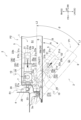
- 2 is a diagram showing a door opening and closing device according to an embodiment and an example of its operation, and is a schematic cross-sectional view for explaining the configuration of the door opening and closing device and its surroundings in a cross-section taken along line II-II in FIG.
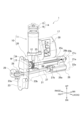
- FIG. 3 is a perspective view showing the door opening and closing device according to the embodiment, for explaining the structure of the actuator.
- FIG. 4 is a block diagram showing an example of the overall configuration of the door opening and closing device according to the embodiment.
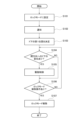
- FIG. 5 is a flowchart showing an example of the operation of the door opening and closing device according to the embodiment.
- FR and RR indicate the front and rear in the vehicle longitudinal direction, respectively.
- LH and RH indicate the left and right in the vehicle width direction, respectively.
- UP and DN indicate the top and bottom in the vehicle vertical direction, respectively.
- the center side of the vehicle in the vehicle width direction is referred to as the inside in the vehicle width direction, and the opposite side to the inside in the vehicle width direction is referred to as the outside in the vehicle width direction.
- the front and rear in the vehicle longitudinal direction, the left and right in the vehicle width direction, and the top and bottom in the vehicle vertical direction are simply referred to as the "front of the vehicle,” “rear of the vehicle,” “left of the vehicle,” “right of the vehicle,” “upper,” and “lower,” respectively. Elements having the same function are given the same reference numerals, and duplicate descriptions will be omitted.
- the inside in the vehicle width direction is indicated by IS
- the outside in the vehicle width direction is indicated by OS.
- the door opening/closing device 1 can be attached to a door 2, which is a vehicle door.
- the door 2 illustrated in FIG. 1 is a member that is attached to the left side of a vehicle body (not shown) so as to be able to open and close. Closing the door 2 blocks an entrance/exit opening formed on the side of the vehicle, and opening the door 2 opens the entrance/exit opening.
- Hinges 3a and 3b are formed on the edge of the door 2 on the front side of the vehicle.
- the door 2 is supported by the hinges 3a and 3b on a wall 4 (see FIG. 2) that defines the entrance of the vehicle body.
- the hinge 3a is formed on the upper part of the front end of the door 2, and the hinge 3b is formed on the lower part of the front end of the vehicle.
- the wall 4 is a wall that defines the front side of the entrance of the vehicle.
- the door 2 can rotate outwardly and inwardly in the vehicle width direction around the support shaft of the hinge 3a and the support shaft of the hinge 3b. Note that “rotation” refers to movement that rotates within a predetermined angle range.
- the shape of the door 2 is not limited to the example shown in the figure, and may be set appropriately depending on, for example, the shape and dimensions of the vehicle body.
- the outer panel 6 described later is omitted from FIG. 1.
- the outer panel 6 is a metal panel material that forms the outer side of the door 2 in the vehicle width direction, and has an approximately rectangular shape overall in a side view.
- the outer panel 6 constitutes part of the exterior surface of the vehicle body. When the door 2 is in a closed state, the outer panel 6 extends approximately in the front-to-rear direction of the vehicle.
- the shapes of the inner panel 5 and the outer panel 6 are not particularly limited, and may be set appropriately depending on the shape of the door 2, for example.
- the door 2 is formed by combining the inner panel 5 and the outer panel 6 in the vehicle width direction and joining the outer periphery. Furthermore, by combining the inner panel 5 and the outer panel 6, a space S1 is formed between them. In the area of the space S1 on the front side of the vehicle, the door opening and closing device 1 is attached to the wall portion 7.
- the closed position P2 illustrated in FIG. 2 is the position where the door 2 is located in a closed state.
- the open position P1 is the position where the door 2 is located in an open state. That is, the open position P1 is the position where the door 2 is located when the boarding/alighting door is open.
- the door 2 is arranged so that the part of the door 2 located further forward in the vehicle width direction is positioned outward than the part of the door 2 journaled on the hinges 3a, 3b.
- the direction in which the door 2 is displaced when it is changed from an open state to a closed state is referred to as the "closing direction.”
- the direction around the pivot of the hinge 3a shown by arrow A in which the door 2 is rotated so as to displace the rear portion of the door 2 inwardly in the vehicle width direction, corresponds to the closing direction.
- the direction in which the door 2 is displaced when it is changed from a closed state to an open state is referred to as the "opening direction.”
- the direction around the pivot of the hinge 3a shown by arrow B, in which the door 2 is rotated so as to displace the rear portion of the door 2 outwardly in the vehicle width direction corresponds to the opening direction.
- the open position P1 illustrated in FIG. 2 is located closer to the closing direction than the fully open position of the door 2. That is, the open position P1 is a position that is set between the closed position P2 and the fully open position.
- the fully open position is the position where the door 2 is located when it is displaced to the maximum in the opening direction. That is, the door 2 is attached to the side of the vehicle so that it can be displaced between the fully open position and the closed position P2.
- a switch 41 which will be described later, may be attached to a predetermined position on the compartment side of the door 2 (see FIG. 1). By operating the switch 41, the occupant can set the operation of the door opening and closing device 1 so that the door 2 does not move in the open direction beyond the open position P1, for example.
- the switch 41 is installed near the inner door handle 43 provided on the compartment side of the door 2, but is not limited to this.
- the shape and dimensions of the door opening and closing device 1 are not limited to the examples shown in the figures.
- the shape and dimensions of the door opening and closing device 1 may be set appropriately depending on the shape and dimensions of the vehicle body or door 2.
- the orientation of the door opening and closing device 1 when attached to the door 2 is not limited to the examples shown in the figures.
- the orientation of the door opening and closing device 1 when attached may be set appropriately depending on the shape of the inner panel 5 or the shape of the wall portion 7.
- the actuator 10 is a unit that applies a driving force to the door 2 at least in the closing direction.
- the actuator 10 illustrated in FIG. 3 includes a motor 11 and a transmission mechanism 20.
- the motor 11 is driven and controlled by a control signal output from a controller 30. Furthermore, the rotation of the motor shaft 12 of the motor 11 is applied to the door 2 via the transmission mechanism 20. Note that the configuration of the actuator 10 is not limited to the example illustrated.
- the motor 11 is an electric component that generates the driving force for the actuator 10, and is disposed at the upper part of the door opening/closing device 1 on the front side of the vehicle.
- the motor 11 is disposed so that its motor shaft 12 extends downward, and the lower part of the casing of the motor 11 is fixed to the upper part of the cover 21 described later using fasteners such as bolts.
- a thread groove is formed on the lower end of the motor shaft 12.
- the thread groove forms a worm 13, which meshes with a worm wheel 24 of the transmission mechanism 20 described later.
- the worm gear W is composed of the worm 13 and the worm wheel 24.
- the type of motor 11 is not particularly limited, and for example, a known electric motor may be used as appropriate depending on the shape, dimensions, weight, etc. of the actuator 10.
- a magnet brake unit 14 may be formed on the upper part of the motor 11.
- the magnet brake unit 14 is composed of a magnetic body 15 and a magnet 16.
- Each of the magnetic body 15 and the magnet 16 has a substantially circular shape in a plan view, and an opening penetrating in the vertical direction is formed in the radial center.
- the upper end of the motor shaft 12 is inserted into the opening of each of the magnetic body 15 and the magnet 16, and the magnetic body 15 is fixed to the end.
- the magnet 16 is fixed to the casing of the motor 11. Therefore, a resistance force due to friction between the magnetic body 15 and the magnet 16 can be applied to the rotation of the motor shaft 12. That is, the magnet brake unit 14 applies resistance to the rotation of the motor shaft 12. This makes it possible to suppress the rotation of the motor shaft 12 when, for example, the rotational force of the worm wheel 24 is input to the worm 13.
- the upper part of the magnet brake unit 14 is formed by the magnetic body 15, and the lower part is formed by the magnet 16, but this is not limited to this.
- the lower part of the magnet brake unit 14 may be formed by the magnetic body 15, and the upper part may be formed by the magnet 16.
- the materials of the magnetic body 15 and the magnet 16 are not particularly limited.
- the magnetic body 15 may be made of a known magnetic metal material, and the magnet 16 may be made of a known permanent magnet.
- the transmission mechanism 20 is a mechanism for transmitting the rotational force of the motor shaft 12 of the motor 11 to the door 2.
- the transmission mechanism 20 is disposed below the motor 11, and includes a cover 21 and a support portion 23.
- the cover 21 constitutes at least a part of the exterior of the transmission mechanism 20.
- the cover 21 extends in approximately the fore-aft direction of the vehicle and has a hollow box shape, with a space S2 formed inside.
- a worm wheel 24, a spindle 25, a slider 26, and an arm 27 are disposed in the space S2.
- the cover 21 has a first wall portion 21a, a second wall portion 21b, a third wall portion 21c, a fourth wall portion 21d, and a fifth wall portion (not shown) that define the space S2 (see Figures 2 and 3).
- the first wall portion 21a forms the outer portion of the cover 21 in the vehicle width direction, and defines the outer side of the space S2 in the vehicle width direction.
- the second wall portion 21b forms the inner portion of the cover 21 in the vehicle width direction, and defines the inner side of the space S2 in the vehicle width direction.
- the third wall portion 21c forms the upper portion of the cover 21, and defines the upper side of the space S2.
- the fourth wall portion 21d forms the rear portion of the cover 21, and defines the rear side of the space S2.
- the fifth wall portion forms the lower portion of the cover 21, and defines the lower side of the space S2.
- Each of the first wall portion 21a, the second wall portion 21b, the third wall portion 21c, and the fifth wall portion illustrated in Figures 2 and 3 extends in approximately the vehicle front-rear direction.
- the fourth wall portion 21d extends in the up-down direction.
- the third wall portion 21c may have a curved shape that is convex upward in a cross section perpendicular to its extension direction.
- a guide portion 22a may be formed on the cover 21.
- the guide portion 22a is a portion that guides the slider 26 that slides within the cover 21.
- the guide portion 22a illustrated in FIG. 3 is formed by causing the lower portion of the first wall portion 21a to bulge outward in the vehicle width direction.
- the lower portion of the second wall portion 21b bulges inward in the vehicle width direction to form a guide portion 22b (see FIG. 2).
- Each of the guide portions 22a and 22b extends in the vehicle front-rear direction. Therefore, the dimension of the lower space that constitutes the lower portion of the space S2 in the vehicle width direction is larger than the dimension of the upper space that constitutes the upper portion of the space S2.
- the transmission mechanism 20 illustrated in FIG. 3 includes a support portion 23.
- the support portion 23 is a portion that supports the door opening/closing device 1 on the door 2.
- the support portion 23 forms the portion of the transmission mechanism 20 on the front side of the vehicle, and a cover 21 extends from the support portion 23 toward the rear of the vehicle.
- the support portion 23 illustrated in FIG. 2 and FIG. 3 extends in the vertical direction as a whole, and has a generally hat-shaped shape that is convex toward the front of the vehicle in a plan view.
- the portion of the support portion 23 facing the front of the vehicle is formed by a wall portion 23a extending in the vertical direction.
- a flange is formed on the rear side of the support portion 23, and this flange and the end of the cover 21 facing the front of the vehicle are fixed using a fastener such as a bolt.
- the wall portion 23a is fixed to the wall portion 7 of the inner panel 5 using a fastener such as a bolt (see Figure 2). In this way, the door opening and closing device 1 is supported by the wall portion 7 in the space S1.
- An opening 23b is provided in the approximate vertical center of the wall portion 23a illustrated in FIG. 3.
- the opening 23b is formed by penetrating a specific area of the wall portion 23a in the vehicle front-rear direction.
- the opening 23b has an approximately rectangular shape when viewed in the vehicle front-rear direction. Space S2 and the external space of the door 2 communicate with each other via the opening 23b.
- the transmission mechanism 20 may also include a worm wheel 24, a spindle 25, a slider 26, and an arm 27.
- the worm wheel 24 is a gear that transmits the rotational force of the motor shaft 12 of the motor 11 to the spindle 25.
- the worm wheel 24 illustrated in the figure is supported by the spindle 25 and disposed at the upper part of the space S2 on the front side of the vehicle.
- the worm wheel 24 also meshes with the worm 13 of the motor 11 to form a worm gear W. Therefore, the rotational force around the central axis of rotation of the motor shaft 12 can be converted into a rotational force around the central axis of rotation of the worm wheel 24.
- the worm wheel 24 is fixed to the end 25a that constitutes the rear side of the spindle 25 so that its central axis of rotation approximately coincides with the central axis of rotation of the spindle 25. Therefore, as the worm wheel 24 rotates, the spindle 25 rotates around its central axis of rotation.
- the spindle 25 is a member that transmits the rotation of the worm wheel 24 to the slider 26.
- the spindle 25 has a cylindrical shape and extends in the fore-and-aft direction of the vehicle in the upper part of the space S2.
- a thread groove 25c is formed in a predetermined range on the outer peripheral surface of the spindle 25 from the end 25b toward the front of the vehicle.
- the end 25b forms the rear side of the spindle 25.
- the worm wheel 24 is attached to the end 25a of the spindle 25.
- the screw groove 25c screws into the screw-in portion 26b of the slider 26, which will be described later. Therefore, the spindle 25 is supported by the slider 26. Note that the area of the outer circumferential surface of the spindle 25 where the screw groove 25c is formed is not particularly limited.
- the slider 26 is a member that can move along the spindle 25.
- the slider 26 illustrated in FIG. 3 has a main body portion 26a and a screw-on portion 26b.
- the main body portion 26a has a block shape that extends in the fore-and-aft direction of the vehicle in the space S2.
- the vertical dimension of the slider 26 is set smaller than the dimensions in the fore-and-aft direction and the vehicle width direction.
- a screw thread portion 26b is formed above the vehicle rear end of the main body portion 26a.
- the screw thread portion 26b extends in the vehicle longitudinal direction and has a substantially circular shape in a cross section perpendicular to the extension direction.
- the lower part of the screw thread portion 26b and the upper surface of the main body portion 26a are integrally connected.
- a screw hole (not shown) that penetrates in the vehicle longitudinal direction is formed in the radial center of the screw thread portion 26b.
- the screw groove 25c of the spindle 25 screws into the screw thread hole. Therefore, as the spindle 25 rotates about the rotation center axis, the slider 26 moves parallel to the rotation center axis within the space S2.
- the arm 27 is a member that connects the wall portion 4 of the vehicle body to the slider 26.
- the arm 27 is a long member that extends in approximately the fore-aft direction of the vehicle, and a cross section perpendicular to the extension direction may have an approximately rectangular shape.
- An end portion 27b on the rear side of the vehicle of the arm 27 is connected to a portion of the main body portion 26a on the front side of the vehicle.
- the main body portion 26a and the end portion 27b may also be connected via a ball joint (not shown).
- the arm 27 extends from the slider 26 through the opening 23b to the region R1 on the vehicle front side of the wall portion 7.
- Region R1 is the space formed between the wall portion 4 and the wall portion 7. Therefore, the end portion 27a on the vehicle front side of the arm 27 is located in the external space of the door 2.
- the arm 27 is inserted into the inside of the cover 21 through the opening 23b from the external space of the door 2, and extends in the space S2 in approximately the fore-and-aft direction of the vehicle.
- End 27a is connected to mounting portion 29 via hinge 28.
- Mounting portion 29 is attached to wall portion 4 of the vehicle body using a fastener such as a bolt. Therefore, arm 27 is rotatably attached to wall portion 4 via hinge 28.
- hinge 28 is disposed in region R1. Furthermore, hinge 28 is disposed inward in the vehicle width direction from hinge 3a that supports door 2 to the vehicle body.
- the length of the portion of the arm 27 that extends toward the external space of the door 2 beyond the opening surface of the opening 23b increases.
- a force that moves away from the wall portion 4 of the vehicle body is input to the actuator 10.
- the actuator 10 since the actuator 10 is fixed to the wall portion 7 of the door 2, the force is transmitted to the door 2. That is, a force that moves the wall portion 7 away from the wall portion 4 is input to the door 2.
- the hinge 28 is located further inward in the vehicle width direction than the hinge 3a.
- the door 2 in the closed state rotates around the support shaft of the hinge 3a as shown by the arrow B in FIG. 2, and the rear side of the door 2 is displaced outward in the vehicle width direction. That is, the door 2 in the closed state is displaced in the opening direction.
- the drive of the motor 11 is controlled so that the motor shaft 12 rotates in the opposite direction to the rotation direction when the closed door 2 is to be opened.
- the slider 26 moves parallel to the extension direction of the spindle 25 toward the fourth wall portion 21d of the cover 21. Therefore, the length of the portion of the arm 27 that extends beyond the opening surface of the opening 23b toward the external space of the door 2 is reduced.
- the open door 2 rotates around the support shaft of the hinge 3a as shown by arrow A in the figure, and the rear side of the door 2 is displaced inward in the vehicle width direction. In other words, the open door 2 is displaced in the closing direction.
- the door opening/closing device 1 is equipped with a sensor 40 that detects the displacement of the door 2 at least in the opening direction (see FIG. 4).
- the location where the sensor 40 is disposed is not particularly limited.
- the sensor 40 may be disposed inside the case 17 (see FIG. 3) that houses the controller 30.
- the sensor 40 can detect, for example, the displacement of the door 2 disposed in the closed position P2 toward the open position P1. Furthermore, when the door 2 disposed in the open position P1 is displaced further in the opening direction, the sensor 40 can detect the displacement.
- the sensor 40 may be a hall sensor, an acceleration sensor, an inclination sensor, etc., or may be configured by combining these sensors in a composite manner.
- the sensor 40 may also detect the displacement of the door 2 in the closing direction. For example, when the door 2 disposed in the open position P1 is displaced in the closing direction, the sensor 40 may detect the displacement. That is, the sensor 40 may detect the displacement of the door 2 in the opening direction and the closing direction.
- the controller 30 controls the actuator 10.
- the actuator 10 is controlled by outputting a signal that controls the drive of the motor 11.
- the controller 30 is housed in a case 17.
- the case 17 has a hollow box shape, and is attached to the actuator 10 in an area behind the motor 11 and above the cover 21.
- the location of the controller 30 is not limited to the example illustrated.
- the case 17 and the controller 30 may be disposed in a location separate from the actuator 10.
- the controller 30 may be a general-purpose microcomputer equipped with a CPU (Central Processing Unit), memory, input/output units, etc.
- a computer program including predetermined rules, instructions, etc. for controlling the actuator 10 is installed in the memory of the microcomputer. By executing the computer program, the microcomputer controls the actuator 10.
- the configuration of the door opening and closing device 1 attached to the door 2 has been described, but the object to which the door opening and closing device 1 is attached is not limited to the door 2.
- the door opening and closing device 1 may be attached to a door equivalent to the door 2, which is attached to the right side of the vehicle body.
- the door and the door opening and closing device 1 attached to the door may have a shape that is symmetrical with respect to a plane that is parallel to the up-down direction and passes through the center line in the vehicle width direction.
- controller 30 will be further described with reference to FIG. 4.
- the controller 30 is electrically connected to the sensor 40 and the actuator 10. Therefore, the controller 30 can receive a signal output by the sensor 40 indicating that the door 2 has been displaced.
- the signal may be a signal indicating that the door 2 has been displaced in the opening direction, or a signal indicating that the door 2 has been displaced in the closing direction.
- the controller 30 can also output a control signal to the actuator 10.
- the controller 30 has a control mode that controls the actuator 10 to restrict the displacement of the door 2 in the opening direction when the door 2 is placed in a predetermined first position.
- the first position is a position of the door 2 that is arbitrarily set between the fully open position and the closed position P2.
- the first position is a predetermined position between the fully open position where the door 2 is located when placed at the most open side, and the closed position P2 that blocks the vehicle entrance.
- the first position is predetermined by the position determination unit 31 described later.
- the first position may be, for example, the open position P1.
- this control mode is referred to as a "lock mode”.
- a control mode different from the lock mode of the controller 30, in which the displacement of the door 2 in the opening direction and the closing direction is not restricted is referred to as a "normal mode".
- the controller 30 may control the actuator 10 in response to a signal input from the sensor 40 indicating that the door 2 has been displaced in the opening direction. At that time, the actuator 10 is controlled to apply a driving force in the closing direction to the door 2. That is, in response to the sensor 40 detecting that the door 2 has been displaced in the opening direction from a predetermined first position, the controller 30 causes the actuator 10 to apply a driving force in the closing direction to the door 2, thereby restricting the displacement of the door 2 in the opening direction.
- the controller 30 illustrated in FIG. 4 is electrically connected to a switch 41. Therefore, the controller 30 can receive an operation signal output by the switch 41, indicating that the switch 41 has been operated. Then, in response to input of the operation signal, the control mode of the controller 30 is set to the lock mode. Also, when an operation signal is input in the lock mode, the lock mode may be released and the controller 30 may be set to the normal mode. Note that the controller 30 may be configured such that, when the door 2 is located in the closed position P2, the lock mode is not set even if the switch 41 is operated.
- the controller 30 may also be electrically connected to a notification unit 42, which will be described later. This allows the controller 30 to output a signal indicating that the door opening and closing device 1 is set to the lock mode to the notification unit 42. Upon receiving this signal, the notification unit 42 notifies the occupant that the door opening and closing device 1 is set to the lock mode. In other words, the door opening and closing device 1 may be provided with a notification unit 42 that notifies that the controller 30 is set to the lock mode.
- the notification unit 42 may be, for example, the switch 41 or a lamp (not shown) installed near the switch 41.
- the lamp may indicate that the door opening and closing device 1 is set to the lock mode by lighting or blinking.
- the lamp may also indicate that the door opening and closing device 1 is not set to the lock mode by turning off the lamp.
- the notification unit 42 is not limited to a lamp.
- the notification unit 42 may notify that the door opening and closing device 1 is set to the lock mode by a notification sound.
- the controller 30 illustrated in FIG. 4 includes a position determination unit 31, a determination unit 32, and a drive control unit 33.
- the position determination unit 31 determines the position where the door 2 is open as the first position. For example, when the switch 41 is operated with the door 2 in the open position P1, the position determination unit 31 determines the open position P1 as the first position. In other words, the first position can be determined by operating the switch 41.
- the position determination unit 31 may store position information of the door 2 indicating the first position.
- the position information may be the opening degree of the door 2 based on the closed position P2.
- the opening degree may be the angle ⁇ formed by a reference line L1 of the door 2 in the open state and a reference line L2 of the door 2 in the closed state.
- the reference lines L1 and L2 represent the posture of the door 2.
- the reference line L2 represents the posture of the door 2 disposed in the closed position P2.
- the reference line L2 also moves together with the rotation of the door 2 disposed in the closed position P2 in the opening direction, and when the door 2 is disposed in the open position P1, it is disposed at the position indicated by the reference line L1. Therefore, the reference line L1 and the reference line L2 correspond to each other, and the reference line L1 represents the posture of the door 2 disposed in the open position P1.
- the reference line L2 passes through the center of the shaft of the hinge 3a and extends parallel to the vehicle longitudinal direction.
- the reference line L1 passes through the center of the shaft of the hinge 3a and extends at an angle relative to the vehicle longitudinal direction so that the closer it is to the rear of the vehicle, the further outward in the vehicle width direction it is. Therefore, in a plan view, an angle ⁇ is formed between the reference lines L1 and L2.
- the angle ⁇ illustrated in the figure is the smaller angle between the reference lines L1 and L2.
- the reference lines L1 and L2 are not limited to the illustrated example, and the reference lines L1 and L2 may be set arbitrarily depending on, for example, the shape of the door 2.
- the door opening/closing device 1 may be configured so that the controller 30 is set to the lock mode by operating the switch 41 when the lock mode is not set. Furthermore, the position determination unit 31 may determine the first position in response to the controller 30 being set to the lock mode. That is, the controller 30 may determine the position of the door 2 when the switch 41 is operated as the first position.
- the manner in which the position determination unit 31 determines the first position is not limited to the method of determining the first position in response to the input of an operation signal.
- the position determination unit 31 may determine a pre-stored position of the door 2 on the vehicle body as the first position. In that case, the door opening and closing device 1 does not need to include the switch 41.
- the position determination unit 31 when the first position is determined, the position determination unit 31 outputs information about the first position to the determination unit 32 and the drive control unit 33.
- the information may be the opening degree of the door 2 placed in the first position.
- the determination unit 32 determines whether the door 2 disposed in the first position has been displaced in the open direction. For example, the determination unit 32 determines that the door 2 has been displaced in the open direction in response to a signal indicating that the door 2 disposed in the open position P1 has been displaced in the open direction being input from the sensor 40 to the controller 30. The determination unit 32 also outputs a first signal indicating that it has been determined that the door 2 has been displaced in the open direction to the drive control unit 33.
- the determination unit 32 may also determine whether the door 2 disposed in the first position has been displaced in the closing direction. For example, the determination unit 32 may determine that the door 2 has been displaced in the closing direction in response to a signal indicating that the door 2 disposed in the open position P1 has been displaced in the closing direction being input from the sensor 40 to the controller 30. The determination unit 32 may also output a second signal indicating that it has been determined that the door 2 has been displaced in the closing direction to the drive control unit 33.
- the drive control unit 33 controls the drive of the actuator 10 in response to the input of the first signal.
- the drive control unit 33 controls the rotational drive of the motor 11.
- the drive control unit 33 controls the rotational direction of the motor shaft 12 so that a driving force that displaces the door 2 in the closing direction is applied to the door 2.
- the drive control unit 33 controls the actuator 10 so that a driving force is applied to the door 2 that cancels the displacement of the door 2 in the opening direction.
- the drive control unit 33 may not control the drive of the actuator 10.
- the drive control unit 33 may assist the displacement of the door 2 in the closing direction by controlling the actuator 10 to apply a driving force in the opening direction or closing direction to the door 2 displacing in the closing direction. That is, when the sensor 40 detects that the door 2 in the first position has been displaced in the closing direction, the controller 30 may control the actuator 10 to allow the door 2 to be displaced in the closing direction. This makes it possible to suppress the actuator 10 from outputting a driving force that counteracts the displacement of the door 2 in the closing direction. Therefore, the door 2 in the first position can be displaced in the closing direction even in the lock mode.
- the actuator 10 may be controlled to apply a driving force in the opening direction to the door 2 displacing in the closing direction, the driving force being set so as not to cancel out the displacement. This can further reduce the displacement speed of the door 2 in the closing direction, and can suppress the generation of excessive noise, for example, when the door 2 is closed.
- the actuator 10 may be controlled to apply a driving force in the closing direction to the door 2 displacing in the closing direction, the driving force being set so as to maintain or increase the displacement speed.
- the door opening/closing device 1 is used to restrict the displacement of the door 2 in the opening direction, for example, when an occupant gets out of the vehicle.
- an obstacle such as another vehicle near the vehicle
- the occupant will position the door 2 at the open position P1, which is closer to the closed position P2 than the position of the door 2 in the fully open state, and then get out of the vehicle.
- the door opening and closing device 1 can restrict only the displacement of the vehicle door 2 in the opening direction at the open position P1, without the need for complicated door operations, by performing the processes of steps S101 to S107 shown in FIG. 5, for example. Therefore, even if an occupant applies a load in the opening direction to the door 2 placed in the open position P1, the displacement of the door 2 in the opening direction is suppressed, and contact between the door 2 and an obstacle can be more reliably avoided.
- the flow illustrated in FIG. 5 is started when an occupant opens the door 2 from a closed state, places it in the open position P1, and operates the switch 41.
- the open position P1 is not particularly limited.
- the open position P1 can be set arbitrarily between the closed position P2 and the position of the door 2 in the fully open state.
- step S101 the control mode of the controller 30 is set to the lock mode in response to the operation signal output by the switch 41 being input to the controller 30. Then, the process proceeds to S102.
- step S102 the notification unit 42 issues a notification to inform the occupant that the door opening/closing device 1 is set to the lock mode.
- the notification may be issued in response to a signal indicating that the door opening/closing device 1 is set to the lock mode being input from the controller 30 to the notification unit 42.
- the notification may also be issued, for example, by turning on a lamp serving as the notification unit 42. After that, the process proceeds to step S103.
- step S103 the position determination unit 31 determines the first position of the door 2.
- the switch 41 is operated with the door 2 placed in the open position P1. Therefore, the position determination unit 31 determines the open position P1 as the first position. After that, the process proceeds to step S104.
- step S104 the determination unit 32 determines whether the door 2 disposed in the first position has been displaced in the open direction.
- the open position P1 is predefined as the first position in step S103. Therefore, the determination unit 32 determines whether the door 2 has been displaced in the open direction based on the open position P1.
- the determination by the determination unit 32 is made according to the signal output from the sensor 40. For example, when a signal indicating that the door 2 disposed in the open position P1 has been displaced in the opening direction is input from the sensor 40, the determination unit 32 determines that the door 2 has been displaced in the opening direction (YES in step S104). The determination unit 32 also outputs a first signal to the drive control unit 33. After that, the process proceeds to step S105.
- the drive control unit 33 does not have to control the drive of the actuator 10 when it receives the second signal from the determination unit 32. For example, when the sensor 40 detects the displacement of the door 2 in the closing direction when the door 2 is in the open position P1, and the determination unit 32 inputs the second signal to the drive control unit 33, the drive control unit 33 does not have to control the drive of the motor 11.
- step S106 the controller 30 determines whether or not a lock mode release operation has been performed.
- the lock mode release operation is an operation that releases the controller 30 from the lock mode. By performing the lock mode release operation, the control mode of the controller 30 can be set to the normal mode. If the controller 30 determines that the lock mode release operation has been performed (YES in step S106), the process proceeds to step S107. If the controller 30 determines that the lock mode release operation has not been performed (NO in step S106), the process returns to step S104, and the displacement of the door 2 in the opening direction, which is disposed in the first position, continues to be monitored. That is, the lock mode is maintained. Therefore, the displacement of the door 2 in the opening direction is suppressed, and contact between the door 2 and an obstacle can be more reliably avoided.
- step S107 the lock mode is released and the control mode of the controller 30 is set to the normal mode. Then, the process ends.
- the door opening and closing device 1 includes an actuator 10 that applies a driving force to a vehicle door 2 in at least the closing direction, a sensor 40 that detects displacement of the door 2 in at least the opening direction, and a controller 30 that controls the actuator 10.
- the controller 30 causes the actuator 10 to apply a driving force to the door 2 in the closing direction, thereby restricting the displacement of the door 2 in the opening direction.
- the door opening and closing device 1 when the open door arranged at the open position P1 tries to move further in the opening direction, a driving force in the closing direction is applied to the door 2. This makes it possible to prevent the open door 2 from opening further. This makes it possible to restrict the movement of the door 2 in the opening direction while suppressing cumbersome operation. In other words, it is possible to restrict the movement of the vehicle door 2 in the opening direction at the open position P1 and to prevent the door from coming into contact with an obstacle without performing cumbersome door operation.
- the door opening and closing device 1 may further include a switch 41 that determines the open position P1.
- the controller 30 may determine the position of the door 2 when the switch 41 is operated as the open position P1.
- the controller 30 may have a lock mode in which, in response to the sensor 40 detecting that the door 2 has been displaced in the opening direction from the open position P1, the actuator 10 applies a driving force in the closing direction to the door 2, thereby restricting the displacement of the door 2 in the opening direction.
- the door opening/closing device 1 described above may further include a notification unit 42 that notifies the user that the controller 30 is set to the lock mode.
Landscapes
- Engineering & Computer Science (AREA)
- Mechanical Engineering (AREA)
- Power-Operated Mechanisms For Wings (AREA)
Abstract
ドア開閉装置は、車両のドアに駆動力を付与するアクチュエータと、ドアの変位を検出するセンサーと、アクチュエータを制御するコントローラと、を備える。コントローラは、ドアが予め定められた第1位置から開方向へ変位したことをセンサーが検出したことに応じて、ドアの開方向への変位を規制する。
Description
本発明は、ドア開閉装置に関する。
下記特許文献1が開示する自動車のドア開閉装置は、回転センサーを通じてドアの開閉操作力を検出する。また、ドアの開閉操作力に応じて、モータによりアシスト力付与部材を駆動して、ドアの開閉をアシストするアシスト力を付与する。開閉操作力が大きいときは、アシスト力を大きく、開閉操作力が小さいときは、アシスト力を小さくする。
ところで、車両用のドアの開閉をドア開閉装置によって行う場合には、ドアを開けた際に、当該ドアが例えば車両の側方に存在する障害物に接触するおそれが有った。また、開いたドアが当該障害物に接触することを回避するためにドアの位置を所定位置に固定した場合は、当該所定位置からドアを移動する際に当該固定を解除する必要があり、ドア操作が煩雑になる。
本発明の目的は、ドア操作を煩雑にすることなく、ドアが障害物に接触することを抑制することができるドア開閉装置を提供することである。
本発明の一態様に係るドア開閉装置は、車両のドアに駆動力を付与するアクチュエータと、ドアの変位を検出するセンサーと、アクチュエータを制御するコントローラと、を備える。コントローラは、ドアが予め定められた第1位置から開方向へ変位したことをセンサーが検出したことに応じて、ドアの開方向への変位を規制する。
本発明によれば、ドア操作を煩雑にすることなく、ドアが障害物に接触することを抑制することが可能なドア開閉装置を提供することができる。
以下、図面を参照しながら、実施形態に係るドア開閉装置について説明する。なお、各図中のFR,RRは、車両前後方向前方、後方の各々を示す。LH,RHは、車幅方向左方、右方の各々を示す。UP,DNは、車両上下方向上方、下方の各々を示す。また、車幅方向における車両中心側を車幅方向内方といい、車幅方向内方とは反対側を車幅方向外方という。以下の説明では、車両前後方向前方、後方、車幅方向左方、右方、車両上下方向上方、下方を、それぞれ単に「車両前方」「車両後方」「車両左方」「車両右方」「上方」「下方」と称する。また、同一の機能を有する要素については同一の符号を付し、重複する説明を省略する。なお、図1~図3に示す例では、車幅方向内方をISで示し、車幅方向外方をOSで示している。
本実施形態に係るドア開閉装置1は、車両用ドアとしてのドア2に取り付けることができる。図1に例示されたドア2は、車体(不図示)の車両左方側の側部に開閉可能に取り付けられる部材である。ドア2を閉じることにより車両の側部に形成された乗降口が閉塞され、ドア2を開くことにより当該乗降口が開放される。
まず、図1及び図2を参照しながら、ドア2が乗降口を閉塞した状態を例にとって、ドア2の構成について説明する。なお、ドア2が開かれ乗降口が開放された状態を「開状態」と称し、乗降口がドア2によって閉塞された状態を「閉状態」と称する。図2では、閉状態のドア2を実線で示し、開状態のドア2を破線で示す。
図1に例示されるドア2はスイングドアであり、側面視で全体として略矩形の形状を有する。ドア2の車両前方側の縁部にはヒンジ3a,3bが形成されている。ドア2はヒンジ3a,3bを介して、車体のうち乗降口を画成する壁部4(図2参照)に支持される。ヒンジ3aはドア2の車両前方側端部の上部に形成され、ヒンジ3bは車両前方側端部の下部に形成されている。壁部4は乗降口の車両前方側を画成する壁部である。ドア2は、ヒンジ3aの支軸及びヒンジ3bの支軸を中心として、車幅方向外方及び車幅方向内方に回動可能である。なお、「回動」とは、所定の角度範囲で回転するように動くことをいう。ドア2の形状は図示された例に限定されず、例えば車両の車体の形状、寸法等に応じて適宜設定されてもよい。また、図1では後述するアウターパネル6の表示を省略した。
図2に例示されるように、ドア2はインナーパネル5とアウターパネル6とを有する。インナーパネル5はドア2の車幅方向内方側を形成する金属製のパネル材であり、側面視で全体として略矩形の形状を有する。また、インナーパネル5は車幅方向内方に向けて膨出するように形成され、図に例示された断面では略ハット型の形状を有する。そのため、閉状態のドア2において、インナーパネル5の車両前方側の部分には、少なくとも一部が車両前後方向において壁部4と対向する壁部7が形成されている。なお、インナーパネル5の車幅方向内方側の面には、車室の内装の一部を構成する、例えば樹脂製のパネル材(不図示)が取り付けられてもよい。
アウターパネル6はドア2の車幅方向外方側を形成する金属製のパネル材であり、側面視で全体として略矩形の形状を有する。アウターパネル6は車体の外装面の一部を構成する。閉状態のドア2においてアウターパネル6は略車両前後方向に延在する。なお、インナーパネル5の及びアウターパネル6の形状は特に限定されず、例えばドア2の形状に応じて適宜設定されてもよい。
例えば、インナーパネル5とアウターパネル6とを車幅方向に組み合わせて外周部を接合することにより、ドア2が形成される。また、インナーパネル5とアウターパネル6とを組み合わせることにより、両者の間には空間S1が形成される。空間S1における車両前方側の領域では、ドア開閉装置1が壁部7に取り付けられている。
図2に例示された閉位置P2は、閉状態のドア2が配置される位置である。ドア2を閉位置P2に配置することによって、車両の車室内と車室外とがドア2によって仕切られる。開位置P1は、開状態のドア2が配置される位置である。即ち、開位置P1は、乗降口が開放された状態においてドア2が配置される位置である。開位置P1において、ドア2はヒンジ3a,3bに軸支された車両前方側の部分よりも、車両前方側の部分が車幅方向外方に位置するように配設される。ドア2を開位置P1に配置することによって、乗降口を介して乗降車が可能となる。
なお、開状態のドア2を閉状態にする際にドア2が変位する方向を「閉方向」という。図2に示された例では、矢印Aに示されるヒンジ3aの支軸周りの方向であって、ドア2の車両後方側の部分を車幅方向内方に向けて変位させるようにドア2を回動させる方向が閉方向に相当する。また、閉状態のドア2を開状態にする際にドア2が変位する方向を「開方向」という。矢印Bに示されるヒンジ3aの支軸周りの方向であって、ドア2の車両後方側の部分を車幅方向外方に向けて変位させるようにドア2を回動させる方向が開方向に相当する。
図2に例示された開位置P1は、ドア2の全開位置よりも閉方向側に位置する。即ち、開位置P1は閉位置P2と全開位置との間において設定される位置である。なお、全開位置は、開方向への変位が最大となっている状態においてドア2が配置される位置である。即ち、ドア2は全開位置と、閉位置P2との間で変位可能に車両側部に取り付けられている。
また、ドア2の車室側の部分における所定位置には、後述するスイッチ41が取り付けられていてもよい(図1参照)。乗員はスイッチ41を操作することにより、ドア2が例えば開位置P1よりも開方向に移動することが無いように、ドア開閉装置1の動作を設定することができる。なお、図1に示された例ではスイッチ41はドア2の車室側に設けられたインナードアハンドル43の近傍に設置されているが、これに限定されない。
次に、図2及び図3を参照しながら、ドア2が閉状態に配置されている場合を例にとって、ドア開閉装置1の構成について更に説明する。ドア開閉装置1はアクチュエータ10と、センサー40と、コントローラ30と、を備える。
なお、ドア開閉装置1の形状及び寸法は各図に示された例に限定されない。例えば、車体又はドア2の形状、寸法等に応じて、ドア開閉装置1の形状及び寸法を適宜設定してもよい。また、ドア2に取り付ける際のドア開閉装置1の姿勢は各図に示された例に限定されない。例えば、インナーパネル5の形状、又は壁部7の形状に応じてドア開閉装置1が取り付けられる際の姿勢を適宜設定してもよい。
アクチュエータ10は少なくとも閉方向の駆動力をドア2に付与するユニットである。図3に例示されたアクチュエータ10は、モータ11と、伝達機構20と、を含む。モータ11はコントローラ30から出力された制御信号によって駆動制御される。また、モータ11のモータ軸12の回転は伝達機構20を介してドア2に付与される。なお、アクチュエータ10の構成は図示された例に限定されない。
モータ11はアクチュエータ10の駆動力を発生させる電気部品であり、ドア開閉装置1の車両前方側上部に配置されている。モータ11は、そのモータ軸12が下方に延出するように配設されており、モータ11のケーシングの下部は後述するカバー21の上部に例えばボルト等の締結具を用いて固定されている。モータ軸12の下方側の端部にはネジ溝が形成されている。当該ネジ溝はウォーム13を形成しており、伝達機構20の後述するウォームホイール24と噛み合う。即ち、ウォーム13及びウォームホイール24によってウォームギアWが構成されている。なお、モータ11の種別は特に限定されず、例えば公知の電動モータをアクチュエータ10の形状、寸法、重量等に応じて適宜用いてもよい。
図3に例示されるように、モータ11の上部にマグネットブレーキ部14が形成されてもよい。マグネットブレーキ部14は、磁性体15と、磁石16とから構成されている。磁性体15及び磁石16の各々は平面視で略円形の形状を有し、径方向中央部に上下方向に貫通する開口が形成されている。磁性体15及び磁石16の各々の当該開口には、モータ軸12の上方側の端部が挿入されており、当該端部には磁性体15が固定されている。また、磁石16はモータ11のケーシングに固定されている。そのため、モータ軸12の回転に対して、磁性体15と磁石16との摩擦に起因する抵抗力を与えることができる。即ち、マグネットブレーキ部14はモータ軸12の回転に抵抗を与える。これにより、例えばウォームホイール24の回転力がウォーム13に入力された際に、モータ軸12が回転することを抑制することができる。
なお、図示された例ではマグネットブレーキ部14の上部を磁性体15が形成しており、下部を磁石16が形成しているが、これに限定されない。マグネットブレーキ部14の下部を磁性体15が形成し、上部を磁石16が形成してもよい。また、磁性体15及び磁石16の材質は特に限定されない。磁性体15は公知の磁性金属材料から構成されてもよく、磁石16は公知の永久磁石から構成されてもよい。
伝達機構20は、モータ11のモータ軸12の回転力をドア2に伝達するための機構である。図3に示された例では、伝達機構20はモータ11の下方に配設されており、カバー21と、支持部23と、を備える。
カバー21は、伝達機構20の外装の少なくとも一部を構成する部分である。カバー21は略車両前後方向に延在すると共に、中空箱形の形状を有し、内部には空間S2が形成されている。空間S2にはウォームホイール24、スピンドル25、スライダ26、及びアーム27が配設されている。カバー21は空間S2を画成する第1壁部21a、第2壁部21b、第3壁部21c、第4壁部21d、及び第5壁部(不図示)を有する(図2及び図3参照)。
第1壁部21aはカバー21の車幅方向外方側の部分を形成し、空間S2の車幅方向外方側を画成する。第2壁部21bはカバー21の車幅方向内方側の部分を形成し、空間S2の車幅方向内方側を画成する。第3壁部21cはカバー21の上部を形成し、空間S2の上方側を画成する。第4壁部21dはカバー21の車両後方側の部分を形成し、空間S2の車両後方側を画成する。第5壁部はカバー21の下部を形成し、空間S2の下方側を画成する。
図2及び図3に例示された第1壁部21a、第2壁部21b、第3壁部21c、及び第5壁部の各々は、略車両前後方向に延在する。第4壁部21dは上下方向に延在する。また、第3壁部21cは、その延在方向に垂直な断面において上方に向けて凸になるように湾曲した形状を有してもよい。
カバー21には案内部22aが形成されてもよい。案内部22aは、カバー21内において摺動するスライダ26を案内する部分である。図3に例示された案内部22aは第1壁部21aの下部を、車幅方向外方に膨出させることにより形成されている。また、第2壁部21bの下部は車幅方向内方に膨出され、案内部22b(図2参照)を形成している。案内部22a及び案内部22bの各々は車両前後方向に延在している。そのため、車幅方向における、空間S2の下部を構成する下部空間の寸法は、空間S2の上部を構成する上部空間の寸法よりも大きい。スライダ26がカバー21内で移動する際には、当該下部空間において案内部22a及び案内部22bに案内されながら摺動する。
図3に例示された伝達機構20は支持部23を備える。支持部23はドア開閉装置1をドア2に支持する部分である。支持部23は伝達機構20の車両前方側の部分を形成しており、支持部23から車両後方に向けてカバー21が延出している。図2及び図3に例示された支持部23は、全体として上下方向に延在し、平面視で車両前方に向けて凸となる略ハット型の形状を有する。
支持部23の車両前方側の部分は上下方向に延在する壁部23aにより形成されている。また、支持部23の車両後方側にはフランジが形成されており、当該フランジと、カバー21の車両前方側の端部とが、例えばボルト等の締結具を用いて固定されている。壁部23aは、インナーパネル5の壁部7に、例えばボルト等の締結具を用いて固定される(図2参照)。これにより、ドア開閉装置1は空間S1において壁部7に支持される。
図3に例示された壁部23aの上下方向略中央部には開口23bが配設されている。開口23bは壁部23aの所定領域を車両前後方向に貫通させることにより形成されている。開口23bは車両前後方向視で略矩形の形状を有する。開口23bを介して空間S2と、ドア2の外部空間とが連通する。
また、図3に例示されるように、伝達機構20はウォームホイール24と、スピンドル25と、スライダ26と、アーム27と、を備えてもよい。
ウォームホイール24はモータ11のモータ軸12の回転力をスピンドル25に伝達する歯車である。図に例示されたウォームホイール24は、スピンドル25に支持されて空間S2の車両前方側上部に配設されている。また、ウォームホイール24は、モータ11のウォーム13に噛み合ってウォームギアWを構成する。そのため、モータ軸12の回転中心軸周りの回転力を、ウォームホイール24の回転中心軸周りの回転力に変換することができる。
ウォームホイール24は、その回転中心軸とスピンドル25の回転中心軸とが略一致するように、スピンドル25の車両後方側を構成する端部25aに固定されている。そのため、ウォームホイール24の回転に伴い、スピンドル25はその回転中心軸周りに回転する。
スピンドル25はウォームホイール24の回転をスライダ26に伝達する部材である。スピンドル25は円柱状の形状を有し、空間S2の上部において車両前後方向に延在する。スピンドル25の外周面には端部25bから車両前方に向けて所定の範囲でネジ溝25cが形成されている。端部25bはスピンドル25の車両後方側を構成する。スピンドル25の端部25aにはウォームホイール24が取り付けられている。
ネジ溝25cはスライダ26の後述する螺合部26bに螺合する。そのため、スピンドル25はスライダ26によって支持される。なお、スピンドル25の外周面のうち、ネジ溝25cが形成される範囲は特に限定されない。
スライダ26はスピンドル25に沿うように移動可能な部材である。図3に例示されたスライダ26は本体部26aと螺合部26bとを有する。本体部26aは、空間S2において車両前後方向に延在するブロック状の形状をする。また、スライダ26の上下方向の寸法は、車両前後方向の寸法及び車幅方向の寸法よりも小さく設定されている。
本体部26aの車両後方側端部の上方には螺合部26bが形成されている。図示された例では、螺合部26bは車両前後方向に延在しており、延在方向に垂直な断面において略円形の形状を有する。また、螺合部26bの下部と、本体部26aの上面とは一体的に接続されている。螺合部26bの径方向中央部には車両前後方向に貫通するネジ孔(不図示)が形成されている。当該ネジ孔にはスピンドル25のネジ溝25cが螺合する。そのため、スピンドル25の回転中心軸周りの回転に伴い、当該回転中心軸に沿うようにして空間S2内をスライダ26が平行移動する。
アーム27は、車体の壁部4とスライダ26とを連結する部材である。アーム27は略車両前後方向に延在する長尺部材であり、延在方向に垂直な断面は略矩形の形状を有してもよい。アーム27の車両後方側の端部27bは本体部26aの車両前方側の部分に接続されている。また、本体部26aと端部27bとはボールジョイント(不図示)を介して接続されてもよい。
図2に例示されるように、アーム27は、スライダ26から開口23bを通じて壁部7の車両前方側の領域R1まで延出している。領域R1は壁部4と壁部7との間に形成された空間である。そのため、アーム27の車両前方側の端部27aはドア2の外部空間に位置している。即ち、アーム27はドア2の外部空間から開口23bを通じてカバー21内部に挿入され、空間S2において略車両前後方向に延在している。
端部27aはヒンジ28を介して取付部29と連結されている。取付部29は車体の壁部4に例えばボルト等の締結具を用いて取り付けられる。そのため、アーム27はヒンジ28を介して壁部4に回動可能に取り付けられる。図に例示されるように、ヒンジ28は領域R1に配設されている。また、ヒンジ28は、ドア2を車体に支持するヒンジ3aよりも車幅方向内方に配設されている。
次に、図2及び図3を参照しながら、閉状態のドア2を開状態にする際の、ドア開閉装置1の動作について説明する。
図3に例示されたアクチュエータ10では、モータ11がコントローラ30から出力された制御信号によって駆動制御されると、モータ軸12は、その回転中心軸周りの所定方向に回転する。モータ軸12の回転はウォームギアWを介してスピンドル25に伝達される。その際、モータ軸12の回転中心軸周りの回転は、スピンドル25の回転中心軸周りの回転に変換される。次に、スピンドル25の回転に伴ってスライダ26の螺合部26bが、図2及び図3の矢印Cに示すように、スピンドル25の延在方向に沿って車両前方に向けて平行移動する。そのため、スライダ26はカバー21の内部において、スピンドル25の延在方向に沿うように車両前方に向けて平行移動することとなる。その結果、アーム27のうち開口23bの開口面よりもドア2の外部空間に向けて延出している部分の長さが増大する。これにより、車体の壁部4から離そうとする力がアクチュエータ10に入力される。ここで、アクチュエータ10はドア2の壁部7に固定されているため、当該力はドア2に伝達される。即ち、ドア2には、壁部7を壁部4から離そうとする力が入力される。また、ヒンジ28はヒンジ3aよりも車幅方向内方に位置する。その結果、閉状態のドア2は図2中の矢印Bに示すように、ヒンジ3aの支軸周りに回動し、ドア2の車両後方側が車幅方向外方に変位する。即ち、閉状態のドア2が開方向に変位する。
開状態のドア2を閉状態にする場合には、閉状態のドア2を開状態にする場合における回転方向とは逆の方向にモータ軸12が回転するように、モータ11の駆動を制御する。これにより、図2中の矢印Dに示されるように、スライダ26はカバー21の内部において、スピンドル25の延在方向に沿って、カバー21の第4壁部21dに向けて平行移動することとなる。そのため、アーム27のうち開口23bの開口面よりもドア2の外部空間に向けて延出している部分の長さが減少する。その結果、開状態のドア2は図中の矢印Aに示すように、ヒンジ3aの支軸周りに回動し、ドア2の車両後方側が車幅方向内方に変位する。即ち、開状態のドア2が閉方向に変位する。
ドア開閉装置1は、少なくとも開方向におけるドア2の変位を検出するセンサー40を備える(図4参照)。なお、センサー40が配設される位置は特に限定されない。例えば、コントローラ30を収容するケース17(図3参照)の内部にセンサー40を配設してもよい。
センサー40は、例えば、閉位置P2に配置されたドア2の開位置P1に向かう変位を検出可能である。また、開位置P1に配置されたドア2が、更に開方向に変位する際に、当該変位をセンサー40は検出可能である。センサー40の種類は特に限定されず、公知のものを適宜用いることができる。例えば、センサー40は、ホールセンサー、加速度センサー、傾斜センサー等であってもよく、また、これらのセンサーを複合的に組み合わせることにより構成されてもよい。
また、センサー40はドア2の閉方向の変位を検出してもよい。例えば、開位置P1に配置されたドア2が閉方向に変位する際に、センサー40は当該変位を検出してもよい。即ち、センサー40はドア2の開方向及び閉方向の変位を検出してもよい。
コントローラ30はアクチュエータ10を制御する。図3に例示されたドア開閉装置1では、モータ11の駆動制御を行う信号を出力することにより、アクチュエータ10を制御する。図示されたドア開閉装置1では、コントローラ30はケース17に収容されている。ケース17は中空箱形の形状を有し、モータ11の車両後方かつカバー21の上方の領域において、アクチュエータ10に取り付けられている。もっとも、コントローラ30の位置は図示された例に限定されない。例えば、ケース17及びコントローラ30は、アクチュエータ10とは別個の位置に配設されてもよい。
コントローラ30は、CPU(Central Processing Unit)、メモリ、入出力部等を備える汎用のマイクロコンピュータであってもよい。マイクロコンピュータのメモリには、アクチュエータ10を制御するための既定のルール、指示等を含むコンピュータプログラムがインストールされている。当該コンピュータプログラムが実行されることにより、マイクロコンピュータはアクチュエータ10の制御を実行する。
以上の説明では、ドア2に取り付けられたドア開閉装置1の構成について説明したが、ドア開閉装置1が取り付けられる対象はドア2に限定されない。例えば、ドア開閉装置1は車体の車両右方側に取り付けられた、ドア2に相当するドアに取り付けられてもよい。その場合には、当該ドア、及び当該ドアに取り付けられたドア開閉装置1は、車両の車幅方向における中心線を通る上下方向に平行な面に対して、面対称の形状を備えてもよい。
次に、図4を参照しながらコントローラ30について更に説明する。
コントローラ30には、センサー40と、アクチュエータ10と、が電気的に接続されている。そのため、コントローラ30は、センサー40が出力するドア2が変位したことを示す信号を受信することができる。当該信号は、ドア2が開方向に変位したことを示す信号であってもよく、ドア2が閉方向に変位したことを示す信号であってもよい。また、コントローラ30はアクチュエータ10に制御信号を出力することができる。
コントローラ30は、予め定められた第1位置に配置されたドア2の開方向への変位を規制するようにアクチュエータ10を制御する制御モードを有する。第1位置とは、全開位置と閉位置P2との間において任意に設定されるドア2の位置である。換言すれば、第1位置とは、最も開方向側に配置された際にドア2が位置する全開位置と、車両の乗降口を閉塞する閉位置P2と、の間において予め定められた位置である。図4に例示されたコントローラ30では、第1位置は後述する位置決定部31によって予め決定される。第1位置は例えば開位置P1であってもよい。なお、以下の説明では当該制御モードを「ロックモード」と称する。また、以下の説明では、コントローラ30のロックモードとは異なる制御モードであって、ドア2の開方向及び閉方向への変位が規制されない制御モードを「通常モード」と称する。
ロックモードに設定された状態において、コントローラ30は、センサー40からドア2が開方向に変位したことを示す信号が入力されたことに応じて、アクチュエータ10を制御してもよい。その際、アクチュエータ10はドア2に対して閉方向の駆動力を付与するように制御される。即ち、コントローラ30は、ドア2が予め定められた第1位置から開方向へ変位したことをセンサー40が検出したことに応じて、アクチュエータ10にドア2に対して閉方向の駆動力を付与させることで、ドア2の開方向への変位を規制する。
図4に例示されたコントローラ30にはスイッチ41が電気的に接続されている。そのため、コントローラ30は、スイッチ41が出力する、スイッチ41が操作されたことを示す操作信号を受信することができる。そして、操作信号が入力されたことに応じて、コントローラ30の制御モードはロックモードに設定される。また、ロックモードにおいて操作信号が入力された場合には、ロックモードが解除され、コントローラ30が通常モードに設定されてもよい。なお、コントローラ30は、ドア2が閉位置P2に配置されている場合には、スイッチ41が操作されてもロックモードに設定されないように構成されてもよい。
またコントローラ30には後述する通知部42が電気的に接続されてもよい。これにより、コントローラ30は、ドア開閉装置1がロックモードに設定されていることを示す信号を通知部42に出力することができる。通知部42は、当該信号を受信すると、ドア開閉装置1がロックモードに設定されていることを乗員に通知する。即ち、ドア開閉装置1は、コントローラ30がロックモードに設定されていること通知する通知部42を備えてもよい。
通知部42は、例えばスイッチ41、又はスイッチ41の近傍に設置されたランプ(不図示)であってもよい。当該ランプは点灯、又は点滅することによりドア開閉装置1がロックモードに設定されていることを示してもよい。また、当該ランプが消灯することにより、ドア開閉装置1がロックモードに設定されていないことを示してもよい。なお、通知部42はランプに限定されない。例えば、通知部42は通知音によってドア開閉装置1がロックモードに設定されていることを通知してもよい。
図4に例示されたコントローラ30は、位置決定部31と、判定部32と、駆動制御部33と、有する。
位置決定部31は、開状態であるドア2が配設された位置を、第1位置と定める。例えば、ドア2が開位置P1に配置された状態においてスイッチ41が操作されると、位置決定部31は開位置P1を第1位置と定める。即ち、第1位置はスイッチ41を操作することにより定めることができる。
なお、位置決定部31は第1位置を示すドア2の位置情報を記憶してもよい。当該位置情報は、閉位置P2を基準としたドア2の開度であってもよい。例えば、図2に示されるように、開状態のドア2における基準線L1と、閉状態のドア2における基準線L2と、が形成する角度θを開度としてもよい。基準線L1,L2はドア2の姿勢を表す。基準線L2は閉位置P2に配置されたドア2の姿勢を表す。また、閉位置P2に配置されたドア2の開方向への回動と共に基準線L2も移動し、ドア2が開位置P1に配置された際には、基準線L1で示される位置に配設される。そのため、基準線L1と基準線L2とは互いに対応しており、基準線L1は開位置P1に配置されたドア2の姿勢を表す。
図示された例では、基準線L2は、ヒンジ3aの支軸の中心を通り車両前後方向に平行に延伸している。また、基準線L1は、ヒンジ3aの支軸の中心を通り、車両後方に向かうほど車幅方向外方に位置するように、車両前後方向に対して傾いて延在している。そのため、平面視において、基準線L1と基準線L2との間には角度θが形成されている。図に例示された角度θは基準線L1と基準線L2とのなす角のうち、小さい方の角度である。なお、基準線L1,L2は図示された例に限定されず、例えばドア2の形状に応じて任意に基準線L1,L2を設定してもよい。
ロックモードに設定されていない状態においてスイッチ41が操作されることにより、コントローラ30がロックモードに設定されるように、ドア開閉装置1を構成してもよい。また、コントローラ30がロックモードに設定されことに応じて、位置決定部31が第1位置を決定してもよい。即ち、コントローラ30は、スイッチ41が操作されたときのドア2の位置を第1位置として定めてもよい。
なお、位置決定部31が第1位置を決定する際の態様は、操作信号の入力に応じて第1位置を決定する方法に限定されない。例えば、位置決定部31は予め記憶された、車体におけるドア2の位置を第1位置として決定してもよい。その場合にはドア開閉装置1はスイッチ41を備えなくてもよい。
図4に示された例では、位置決定部31は第1位置が決定された際に、第1位置に関する情報を判定部32及び駆動制御部33に出力する。当該情報は、第1位置に配置されたドア2の開度であってもよい。
判定部32は、第1位置に配置されたドア2が開方向に変位したか否かの判定を行う。例えば、判定部32は、開位置P1に配置されたドア2が開方向に変位したことを示す信号がセンサー40からコントローラ30に入力されたことに応じて、ドア2が開方向に変位したと判定する。また、判定部32は、ドア2が開方向に変位したと判定したことを示す第1信号を駆動制御部33に出力する。
また、判定部32は、第1位置に配置されたドア2が閉方向に変位したか否かの判定を行ってもよい。例えば、判定部32は、開位置P1に配置されたドア2が閉方向に変位したことを示す信号がセンサー40からコントローラ30に入力されたことに応じて、ドア2が閉方向に変位したと判定してもよい。また、判定部32は、ドア2が閉方向に変位したと判定したことを示す第2信号を駆動制御部33に出力してもよい。
駆動制御部33は、第1信号が入力されたことに応じて、アクチュエータ10の駆動制御を行う。図4に示された例では、駆動制御部33はモータ11の回転駆動の制御を行う。その際、駆動制御部33は、ドア2を閉方向に変位させる駆動力がドア2に付与されるように、モータ軸12の回転方向を制御する。より詳細には、駆動制御部33は、ドア2の開方向への変位が打ち消されるような駆動力をドア2に付与するように、アクチュエータ10を制御する。これにより、例えば第1位置としての開位置P1に配置されたドア2が開方向に変位しようとした場合であっても、当該変位と、アクチュエータ10から付与される駆動力に起因する閉方向への変位と、がバランスされることとなる。即ち、開位置P1に位置するドア2の開方向への変位が規制される。
駆動制御部33は、第2信号が入力された場合には、アクチュエータ10の駆動制御を行わなくてもよい。例えば、第1位置としての開位置P1に配置されたドア2の閉方向への変位をセンサー40が検出した場合には、駆動制御部33はモータ11の駆動制御を行わなくてもよい。なお、第2信号が入力された場合における駆動制御部33の動作はこれに限定されない。例えば、駆動制御部33は、閉方向に変位するドア2に対して開方向、又は閉方向の駆動力を付与するようにアクチュエータ10を制御することで、ドア2の閉方向への変位をアシストしてもよい。即ち、コントローラ30は、第1位置のドア2が閉方向へ変位したことをセンサー40が検出した際に、ドア2の閉方向への変位を許容するように、アクチュエータ10を制御してもよい。これにより、ドア2の閉方向への変位を打ち消すような駆動力をアクチュエータ10が出力することを抑制できる。そのため、ロックモードであっても第1位置のドア2を閉方向に変位させることができる。
ある実施形態では、閉方向に変位するドア2に対して、当該変位を打ち消さないように設定された開方向の駆動力を付与するように、アクチュエータ10を制御してもよい。これにより、ドア2の閉方向への変位速度をより低減し、例えばドア2が閉状態となる際に過大な音が発生することを抑制することができる。また、ある実施形態では、閉方向に変位するドア2に対して、当該変位の速度を維持又は増大させるように設定された閉方向の駆動力を付与するように、アクチュエータ10を制御してもよい。これにより、例えば、車両左方側が車両右方側よりも上下方向における位置が低くなるように傾いた姿勢で車両が停車されたことに起因して、ドア2に開方向の荷重が入力されている場合であっても、より確実にドア2を閉位置P2まで変位させることができる。
次に、図5を参照しながら、ドア開閉装置1の動作の一例について説明する。
ドア開閉装置1を用いたドア2の開方向への変位の規制は、例えば乗員が降車する際に行われる。車両を駐車しドア2を開ける際、車両近傍に他の車両等の障害物が存在すると、当該障害物とドア2との接触を避けるために、ドア2を全開状態にすることができない場合が有る。そのような場合には、乗員は全開状態におけるドア2の位置よりも閉位置P2側の位置である開位置P1にドア2を配置し、降車することとなる。
ここで、ドア開閉装置1によれば、例えば図5に示すステップS101~ステップS107の処理を行うことにより、煩雑なドア操作を行うことなく、開位置P1における車両用のドア2の開方向への変位のみを規制することができる。そのため、乗員が開位置P1に配置されたドア2に開方向の荷重を入力したとしても、ドア2の開方向への変位が抑制され、障害物とドア2との接触をより確実に避けることができる。
図5に例示されるフローは、乗員が閉状態のドア2を開けて開位置P1に配置し、スイッチ41を操作することにより開始される。なお、開位置P1は特に限定されない。開位置P1は、閉位置P2と、全開状態におけるドア2の位置と、の間において任意に設定することができる。
ステップS101では、スイッチ41が出力した操作信号がコントローラ30に入力されたことに応じて、コントローラ30の制御モードがロックモードに設定される。その後、処理はS102に進む。
ステップS102では、通知部42が、ドア開閉装置1がロックモードに設定されていることを乗員に知らせるための通知を行う。当該通知は、ドア開閉装置1がロックモードに設定されていることを示す信号がコントローラ30から通知部42に入力されたことに応じて行われてもよい。また、当該通知は例えば通知部42としてのランプを点灯させることにより行われてもよい。その後、処理はステップS103に進む。
ステップS103では、位置決定部31がドア2の第1位置を決定する。図示されたフローでは、ドア2が開位置P1に配置された状態でスイッチ41が操作されている。そのため、位置決定部31は開位置P1を第1位置と定める。その後、処理はステップS104に進む。
ステップS104では、判定部32が、第1位置に配置されたドア2が開方向に変位したか否か判定する。図示されたフローでは、ステップS103において開位置P1が第1位置として予め定められている。そのため、判定部32は、開位置P1を基準としてドア2が開方向に変位したか否かを判定する。
判定部32による判定は、センサー40から出力される信号に応じて行われる。例えば、センサー40から開位置P1に配置されたドア2が開方向に変位したことを示す信号が入力されると、判定部32はドア2が開方向に変位したと判定する(ステップS104でYES)。また、判定部32は第1信号を駆動制御部33に出力する。その後、処理はステップS105に進む。
一方、センサー40からドア2が開方向に変位したことを示す信号が入力されない場合には、判定部32はドア2が開方向に変位していないと判定する(ステップS104でNO)。その後、処理はステップS106に進む。
ステップS105では、駆動制御部33がアクチュエータ10の駆動制御を行う。その際、駆動制御部33は、ドア2を閉方向に変位させる駆動力がドア2に付与されるように、アクチュエータ10を制御する。より詳細には、駆動制御部33は、ドア2の開方向への変位が打ち消されるように、モータ軸12の回転を制御する。これにより、開位置P1に位置するドア2が開方向に変位しようとした場合であっても、当該変位と、アクチュエータ10から付与される駆動力に起因する閉方向への変位と、がバランスされ、ドア2の開方向への変位が規制される。その後、処理はステップS106に進む。
なお、駆動制御部33は、判定部32から第2信号を受信した場合には、アクチュエータ10の駆動制御を行わなくてもよい。例えば、開位置P1に配置されたドア2の閉方向への変位をセンサー40が検出し、判定部32が駆動制御部33に第2信号を入力した場合には、駆動制御部33はモータ11の駆動制御を行わなくてもよい。
ステップS106では、コントローラ30はロックモード解除操作が行われたか否かを判定する。ロックモード解除操作はコントローラ30をロックモードから解除する操作である。ロックモード解除操作を行うことにより、コントローラ30の制御モードを通常モードに設定することができる。ロックモード解除操作が行われたとコントローラ30が判定した場合には(ステップS106でYES)、処理はステップS107に進む。また、ロックモード解除操作が行われていないとコントローラ30が判定した場合には(ステップS106でNO)、処理はステップS104へと戻り、第1位置に配置されたドア2の開方向への変位が引き続き監視される。即ち、ロックモードが維持される。そのため、ドア2の開方向への変位が抑制され、障害物とドア2との接触をより確実に避けることができる。
ロックモード解除操作はスイッチ41を操作することにより行われてもよい。即ち、コントローラ30は、スイッチ41からの操作信号を受信したことに応じてロックモード解除操作が行われたと判定してもよい。また、ロックモード解除操作はドア2を閉方向に変位させる操作であってもよい。より詳細には、コントローラ30は、センサー40がドア2の閉方向への変位を検出し、第1位置に配置されたドア2が閉方向に変位したと判定部32が判定したことに応じて、ロックモード解除操作が行われたと判定してもよい。例えば、降車した乗員が開位置P1に配置されたドア2を閉める操作を行った場合に、コントローラ30はロックモード解除操作が行われたと判定する。
ステップS107では、ロックモードが解除され、コントローラ30の制御モードが通常モードに設定される。その後、処理は終了する。
なお、例えば乗員が降車し、ドア2が閉状態にされたことに応じて、第1位置を示すドア2の位置情報はリセットされてもよい。また、ドア開閉装置1の動作は図5に示された例に限定されない。例えば、ステップS102の処理は、ステップS103とステップS104との間で行われてもよい。
以下、実施形態に係るドア開閉装置の作用効果について説明する。
(1)実施形態に係るドア開閉装置1は、車両のドア2に少なくとも閉方向の駆動力を付与するアクチュエータ10と、ドア2の少なくとも開方向の変位を検出するセンサー40と、アクチュエータ10を制御するコントローラ30と、を備える。コントローラ30は、ドア2が予め定められた開位置P1から開方向へ変位したことをセンサー40が検出したことに応じて、アクチュエータ10にドア2に対して閉方向の駆動力を付与させることで、ドア2の開方向への変位を規制する。
実施形態に係るドア開閉装置1によれば、開位置P1に配置された開状態のドアが、更に開方向へ変位しようとする場合には、ドア2に閉方向の駆動力が付与される。そのため、開状態のドア2が更に開くことを抑制することができる。よって、ドア2の煩雑な操作を抑制しながら、開方向への変位を規制することができる。即ち、煩雑なドア操作を行うことなく、開位置P1における車両用のドア2の開方向への変位を規制し、ドアが障害物に接触することを抑制することができる。
(2)センサー40はドア2の開方向及び閉方向の変位を検出し、コントローラ30は、開位置P1のドア2が閉方向へ変位したことをセンサー40が検出した際に、ドア2の閉方向への変位を許容するように、アクチュエータ10を制御してもよい。
これにより、開位置P1に配置されたドア2が閉方向に変位した際、ドア2の閉方向への変位を打ち消すような駆動力をアクチュエータ10が出力することを抑制できる。そのため、開位置P1のドア2をより確実に閉方向に変位させることができる。
(3)上記ドア開閉装置1は、開位置P1を定めるスイッチ41を更に備えてもよい。
これにより、乗員がスイッチ41を操作することにより、開位置P1を定めることができる。そのため、ドア2の開方向への変位を規制する開位置P1を、より好適な位置に設定することが可能なドア開閉装置1を提供することができる。
(4)コントローラ30は、スイッチ41が操作されたときのドア2の位置を開位置P1として定めてもよい。
これにより、例えば開位置P1にドア2が配置された状態で乗員がスイッチ41を操作された場合、開位置P1より開方向へのドア2の変位が規制される。そのため、乗員がドア2の位置を手動で微調整した後にスイッチ41を操作することで、ドア2の開方向への変位が規制されるドア開閉装置1を提供することができる。即ち、開位置P1をより適切な位置に設定可能な、ドア開閉装置1を提供することができる。
(5)コントローラ30は、ドア2が開位置P1から開方向へ変位したことをセンサー40が検出したことに応じて、アクチュエータ10にドア2に対して閉方向の駆動力を付与させることで、ドア2の開方向への変位を規制するロックモードを有してもよい。また、上述のドア開閉装置1は、コントローラ30がロックモードに設定されていること通知する通知部42を更に備えてもよい。
これにより、ドア開閉装置1のコントローラ30がロックモードに設定されていることを、より確実に視認可能なドア開閉装置1を提供することができる。
上記実施形態は、発明の理解を容易にするために記載された単なる例示に過ぎない。発明の技術的範囲は、上記実施形態で開示した具体的な技術事項に限らず、そこから容易に導きうる様々な変形、変更、代替技術なども含むものである。
本出願は、2023年6月9日に出願された日本出願2023-095537に基づく優先権を主張しており、該出願の全内容が参照により本明細書に組み込まれる。
1 ドア開閉装置
2 ドア
10 アクチュエータ
30 コントローラ
40 センサー
41 スイッチ
42 通知部
P1 開位置(第1位置)
2 ドア
10 アクチュエータ
30 コントローラ
40 センサー
41 スイッチ
42 通知部
P1 開位置(第1位置)
Claims (5)
- 車両のドアに少なくとも閉方向の駆動力を付与するアクチュエータと、
前記ドアの少なくとも開方向の変位を検出するセンサーと、
前記アクチュエータを制御するコントローラと、を備え、
前記コントローラは、前記ドアが予め定められた第1位置から前記開方向へ変位したことを前記センサーが検出したことに応じて、前記アクチュエータに前記ドアに対して前記閉方向の駆動力を付与させることで、前記ドアの前記開方向への変位を規制する、ドア開閉装置。 - 前記センサーは、前記ドアの前記開方向及び前記閉方向の変位を検出し、
前記コントローラは、前記第1位置の前記ドアが前記閉方向へ変位したことを前記センサーが検出した際に、前記ドアの前記閉方向への変位を許容するように前記アクチュエータを制御する、請求項1に記載のドア開閉装置。 - 前記第1位置を定めるスイッチを更に備える、請求項1又は2に記載のドア開閉装置。
- 前記コントローラは、前記スイッチが操作されたときの前記ドアの位置を前記第1位置として定める、請求項3に記載のドア開閉装置。
- 請求項4に記載のドア開閉装置であって、
前記コントローラは、前記ドアが前記第1位置から前記開方向へ変位したことを前記センサーが検出したことに応じて、前記アクチュエータに前記ドアに対して前記閉方向の駆動力を付与させることで、前記ドアの前記開方向への変位を規制する制御モードを有し、
前記コントローラが前記制御モードに設定されていること通知する通知部を更に備える、ドア開閉装置。
Priority Applications (2)
| Application Number | Priority Date | Filing Date | Title |
|---|---|---|---|
| CN202480037773.9A CN121443822A (zh) | 2023-06-09 | 2024-05-29 | 门开闭装置 |
| JP2025526067A JPWO2024252994A1 (ja) | 2023-06-09 | 2024-05-29 |
Applications Claiming Priority (2)
| Application Number | Priority Date | Filing Date | Title |
|---|---|---|---|
| JP2023-095537 | 2023-06-09 | ||
| JP2023095537 | 2023-06-09 |
Publications (1)
| Publication Number | Publication Date |
|---|---|
| WO2024252994A1 true WO2024252994A1 (ja) | 2024-12-12 |
Family
ID=93795981
Family Applications (1)
| Application Number | Title | Priority Date | Filing Date |
|---|---|---|---|
| PCT/JP2024/019620 Ceased WO2024252994A1 (ja) | 2023-06-09 | 2024-05-29 | ドア開閉装置 |
Country Status (3)
| Country | Link |
|---|---|
| JP (1) | JPWO2024252994A1 (ja) |
| CN (1) | CN121443822A (ja) |
| WO (1) | WO2024252994A1 (ja) |
Citations (6)
| Publication number | Priority date | Publication date | Assignee | Title |
|---|---|---|---|---|
| JP2006027483A (ja) * | 2004-07-16 | 2006-02-02 | Denso Corp | 自動車用ドア操作アシストシステム |
| JP2006028936A (ja) * | 2004-07-16 | 2006-02-02 | Denso Corp | 自動車用ドア操作アシストシステム |
| JP2008121196A (ja) * | 2006-11-08 | 2008-05-29 | Mazda Motor Corp | 車両用ドアの開閉装置 |
| JP2009108495A (ja) * | 2007-10-26 | 2009-05-21 | Mitsubishi Motors Corp | ドア開動作規制装置 |
| US20170291477A1 (en) * | 2016-04-12 | 2017-10-12 | Ford Global Technologies, Llc | Vehicle door assist assembly incorporating a high torque operating mechanism |
| JP2023057712A (ja) * | 2021-10-12 | 2023-04-24 | 日産自動車株式会社 | 車両用ドアの開閉装置 |
-
2024
- 2024-05-29 WO PCT/JP2024/019620 patent/WO2024252994A1/ja not_active Ceased
- 2024-05-29 JP JP2025526067A patent/JPWO2024252994A1/ja active Pending
- 2024-05-29 CN CN202480037773.9A patent/CN121443822A/zh active Pending
Patent Citations (6)
| Publication number | Priority date | Publication date | Assignee | Title |
|---|---|---|---|---|
| JP2006027483A (ja) * | 2004-07-16 | 2006-02-02 | Denso Corp | 自動車用ドア操作アシストシステム |
| JP2006028936A (ja) * | 2004-07-16 | 2006-02-02 | Denso Corp | 自動車用ドア操作アシストシステム |
| JP2008121196A (ja) * | 2006-11-08 | 2008-05-29 | Mazda Motor Corp | 車両用ドアの開閉装置 |
| JP2009108495A (ja) * | 2007-10-26 | 2009-05-21 | Mitsubishi Motors Corp | ドア開動作規制装置 |
| US20170291477A1 (en) * | 2016-04-12 | 2017-10-12 | Ford Global Technologies, Llc | Vehicle door assist assembly incorporating a high torque operating mechanism |
| JP2023057712A (ja) * | 2021-10-12 | 2023-04-24 | 日産自動車株式会社 | 車両用ドアの開閉装置 |
Also Published As
| Publication number | Publication date |
|---|---|
| JPWO2024252994A1 (ja) | 2024-12-12 |
| CN121443822A (zh) | 2026-01-30 |
Similar Documents
| Publication | Publication Date | Title |
|---|---|---|
| US10801246B2 (en) | Programmable door power assist | |
| US9834974B2 (en) | Automotive door power assist | |
| EP1997996B1 (en) | Pinch prevention of slide device | |
| US9879465B2 (en) | Programmable door power assist | |
| US9676256B2 (en) | Power assist device for a vehicle door | |
| US20170030137A1 (en) | Automotive door power assist | |
| US11142937B2 (en) | Opening and closing device | |
| US20170030118A1 (en) | Door closure and latching confirmation system | |
| US20070284905A1 (en) | Vehicle Seat with Swing-Out Lower Seat Portion | |
| JP2020083148A (ja) | 車両用ドア制御装置 | |
| KR20080003724A (ko) | 차량용 도어 래치 디바이스 | |
| JP3052491B2 (ja) | 自動車用自動ドアの安全装置 | |
| JP2005171575A (ja) | 車両用自動開閉装置 | |
| CN121443822A (zh) | 门开闭装置 | |
| JP7817218B2 (ja) | スライドドア用給電装置 | |
| JPH01314620A (ja) | 車両用バックドアの自動開閉装置 | |
| US20160059679A1 (en) | Electric swing door and operating method thereof | |
| JP3960328B2 (ja) | 車両用開閉部材の自動開閉装置 | |
| JP2006117089A (ja) | 車両用制御装置 | |
| JP2006316489A (ja) | ドアの開閉制御装置 | |
| JP7581888B2 (ja) | 車両用ドアの開閉装置 | |
| JP2006028936A (ja) | 自動車用ドア操作アシストシステム | |
| JP2004116027A (ja) | 挟み込み検出装置 | |
| JP2002178755A (ja) | 車両の開閉体構造 | |
| JP4487794B2 (ja) | 車両用ドアの自動開閉装置 |
Legal Events
| Date | Code | Title | Description |
|---|---|---|---|
| 121 | Ep: the epo has been informed by wipo that ep was designated in this application |
Ref document number: 24819225 Country of ref document: EP Kind code of ref document: A1 |
|
| ENP | Entry into the national phase |
Ref document number: 2025526067 Country of ref document: JP Kind code of ref document: A |
|
| NENP | Non-entry into the national phase |
Ref country code: DE |