WO2024252993A1 - 指輪型デバイス - Google Patents
指輪型デバイス Download PDFInfo
- Publication number
- WO2024252993A1 WO2024252993A1 PCT/JP2024/019604 JP2024019604W WO2024252993A1 WO 2024252993 A1 WO2024252993 A1 WO 2024252993A1 JP 2024019604 W JP2024019604 W JP 2024019604W WO 2024252993 A1 WO2024252993 A1 WO 2024252993A1
- Authority
- WO
- WIPO (PCT)
- Prior art keywords
- finger
- vibration element
- ring
- vibration
- arm
- Prior art date
- Legal status (The legal status is an assumption and is not a legal conclusion. Google has not performed a legal analysis and makes no representation as to the accuracy of the status listed.)
- Ceased
Links
Images











Classifications
-
- G—PHYSICS
- G06—COMPUTING OR CALCULATING; COUNTING
- G06F—ELECTRIC DIGITAL DATA PROCESSING
- G06F3/00—Input arrangements for transferring data to be processed into a form capable of being handled by the computer; Output arrangements for transferring data from processing unit to output unit, e.g. interface arrangements
- G06F3/01—Input arrangements or combined input and output arrangements for interaction between user and computer
- G06F3/016—Input arrangements with force or tactile feedback as computer generated output to the user
-
- G—PHYSICS
- G06—COMPUTING OR CALCULATING; COUNTING
- G06F—ELECTRIC DIGITAL DATA PROCESSING
- G06F3/00—Input arrangements for transferring data to be processed into a form capable of being handled by the computer; Output arrangements for transferring data from processing unit to output unit, e.g. interface arrangements
- G06F3/01—Input arrangements or combined input and output arrangements for interaction between user and computer
-
- G—PHYSICS
- G06—COMPUTING OR CALCULATING; COUNTING
- G06F—ELECTRIC DIGITAL DATA PROCESSING
- G06F3/00—Input arrangements for transferring data to be processed into a form capable of being handled by the computer; Output arrangements for transferring data from processing unit to output unit, e.g. interface arrangements
- G06F3/01—Input arrangements or combined input and output arrangements for interaction between user and computer
- G06F3/011—Arrangements for interaction with the human body, e.g. for user immersion in virtual reality
- G06F3/014—Hand-worn input/output arrangements, e.g. data gloves
-
- G—PHYSICS
- G06—COMPUTING OR CALCULATING; COUNTING
- G06F—ELECTRIC DIGITAL DATA PROCESSING
- G06F3/00—Input arrangements for transferring data to be processed into a form capable of being handled by the computer; Output arrangements for transferring data from processing unit to output unit, e.g. interface arrangements
- G06F3/01—Input arrangements or combined input and output arrangements for interaction between user and computer
- G06F3/03—Arrangements for converting the position or the displacement of a member into a coded form
- G06F3/033—Pointing devices displaced or positioned by the user, e.g. mice, trackballs, pens or joysticks; Accessories therefor
-
- H—ELECTRICITY
- H01—ELECTRIC ELEMENTS
- H01Q—ANTENNAS, i.e. RADIO AERIALS
- H01Q1/00—Details of, or arrangements associated with, antennas
- H01Q1/27—Adaptation for use in or on movable bodies
- H01Q1/273—Adaptation for carrying or wearing by persons or animals
-
- G—PHYSICS
- G06—COMPUTING OR CALCULATING; COUNTING
- G06F—ELECTRIC DIGITAL DATA PROCESSING
- G06F2203/00—Indexing scheme relating to G06F3/00 - G06F3/048
- G06F2203/033—Indexing scheme relating to G06F3/033
- G06F2203/0331—Finger worn pointing device
-
- G—PHYSICS
- G06—COMPUTING OR CALCULATING; COUNTING
- G06F—ELECTRIC DIGITAL DATA PROCESSING
- G06F2203/00—Indexing scheme relating to G06F3/00 - G06F3/048
- G06F2203/038—Indexing scheme relating to G06F3/038
- G06F2203/0384—Wireless input, i.e. hardware and software details of wireless interface arrangements for pointing devices
Definitions
- the present invention relates to a ring-type device used to operate an information processing device.
- a ring-shaped operation device that is worn on the finger has appeared as a device for operating an information processing device (Patent Document 1), and has been attracting attention in recent years as an operation input means to replace conventional mice, keyboards, touch pads, etc.
- such a ring-type device is as lightweight as possible.
- the fit when worn on the finger is also important. In other words, whether or not a stable position can be maintained when the device is worn on the finger, and whether or not wearing the device forces the finger or hand into an unnatural position or causes discomfort, etc.
- whether or not various operations can be easily performed when the device is worn on the finger in other words, operability, is also important.
- Some ring-type devices have built-in vibration elements as so-called haptic devices. Because vibration elements are the most power-consuming component among the various mounted parts, they need to vibrate efficiently with as little power as possible. In particular, it is difficult to install large-capacity batteries in ring-type devices, so they need to transmit vibrations efficiently with little power.
- the object of the present invention is to provide a technology that allows a user to sense vibrations more efficiently and effectively in a ring-type device equipped with a vibration element.
- the ring-type device of the present invention comprises: A ring-type device that is worn on a user's finger, An annular body surrounding the mounting space; A vibration element provided inside the annular body; A control unit that controls the vibration element; Equipped with A virtual line passing through the vibration element along the vibration axis of the vibration element passes through the mounting space.
- the present invention allows a user to sense vibrations more efficiently and effectively in a ring-type device equipped with a vibration element.
- FIG. 1A to 1C are schematic diagrams showing the configuration of a finger ring device 1 according to a first embodiment of the present invention.
- 2A and 2B are diagrams illustrating an outline of the information processing system 100.
- FIG. FIG. 3 is a diagram illustrating the control configuration of the information processing system 100.
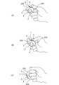
- 4A to 4C are schematic diagrams showing an example of how the finger ring type device 1 is worn.
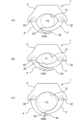
- 5A to 5C are schematic diagrams illustrating changes in posture of the first arm 3 and the second arm 4.
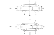
- FIG. 6A and 6B are bottom views of the finger ring type device 1.
- FIG. 7A and 7B are schematic diagrams of the first arm portion 3.
- FIG. FIG. 8 is a schematic diagram showing the configuration of the finger ring type device 1. As shown in FIG. FIG.
- FIG. 9 is a schematic diagram showing the configuration of the finger ring type device 1.
- FIG. 10 is a schematic diagram showing a modified configuration of the finger ring type device 1.
- FIG. 11 is a schematic diagram showing a modified configuration of the finger ring type device 1.
- FIG. 12 is a schematic diagram showing a modified configuration of the finger ring type device 1.
- FIG. 13 is a schematic diagram showing the configuration of the finger ring type device 1.
- FIG. 14 is a schematic front view showing the configuration of the finger ring type device 1.
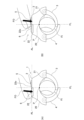
- FIG. 15A and 15B are schematic diagrams showing the configuration of a finger ring type device according to a comparative example.
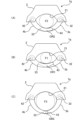
- FIG. 16A to 16C are schematic cross-sectional views showing the configuration of the finger ring type device 1.
- FIG. 17 is a schematic side view showing the configuration of the finger ring type device 1.
- FIG. 18 is a schematic diagram showing the configuration of the operated surface of the finger ring type device 1.
- FIG. 19 is a schematic cross-sectional view taken along the line E in FIG. 20A and 20B are schematic cross-sectional views taken along the line F in FIG. 18.
- FIG. 21 is a schematic diagram showing the configuration of the operated surface of the finger ring type device 1.
- FIG. 22 is a schematic front view of a finger ring type device 1d according to a modified example.
- 23A and 23B are schematic front views of the finger ring type device 1.
- FIG. 24A and 24B are schematic front views of a finger ring type device 1e according to Comparative Example 3.
- FIG. 25A and 25B are schematic front views of a finger ring type device 1f according to Comparative Example 4.
- FIG. 26A to 26C are schematic diagrams illustrating changes in posture of the first arm 3b and the second arm 4b.
- 27A and 27B are bottom views of the finger ring type device 1g.
- FIG. 28 is a bottom view of the finger ring type device 1g.
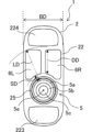
- FIG. 1A is a diagram of the finger ring type device 1 as viewed in the direction of finger insertion, and is a front view of the finger ring type device 1.
- Fig. 1B is a view taken along the arrow A in Fig. 1A, and is a top view showing the configuration of the operated surface of the finger ring type device 1.
- Fig. 1C is a view taken along the arrow B in Fig. 1A, and is a side view of the finger ring type device 1.
- the ring-type device 1 of this embodiment has a generally annular outer shape, with a central hole through which the user can insert the finger F. More specifically, the ring-type device 1 includes a main body 2, a first arm 3, and a second arm 4, which are connected in a ring shape to form a wearing space FS into which the user's finger F can be inserted (forming a ring-shaped body surrounding the wearing space FS).
- annular does not only refer to an annular configuration that completely closes the outer periphery of the mounting space FS, but also to a shape configuration that is partially discontinuous, such as a roughly C-shape, but has a roughly annular shape overall.
- the main body 2 has an exterior 20 that is roughly arc-shaped, and the exterior 20 has a concave arc-shaped inner surface 21 that forms the mounting space FS, and an outer surface 22 opposite the inner surface 21.
- the first arm 3 is connected to the first end 23, which is one end of the main body 2 in the direction surrounding the mounting space FS, and extends in a generally arc shape from the first end 23 of the main body 2 in one direction (first direction) in the surrounding direction.
- the first arm 3 has a concave arc-shaped inner surface 31 that forms the mounting space FS, and the inner surface 31 faces the inner surface 21 of the main body 2 across the mounting space FS.
- the first arm 3 is rotatably attached to the first end 23 of the main body 2 so that the opposing distance between the inner surface 31 and the inner surface 21 of the main body 2 can be changed.
- the second arm 4 is connected to the second end 24, which is the other end of the main body 2 in the direction surrounding the mounting space FS, and extends in a generally arc shape from the second end 24 of the main body 2 in the other direction (second direction) in the surrounding direction.
- the second arm 4 has a concave arc-shaped inner surface 41 that forms the mounting space FS, and the inner surface 41 faces the inner surface 21 of the main body 2 across the mounting space FS.
- the second arm 4 is rotatably attached to the second end 24 of the main body 2 so that the opposing distance between the inner surface 41 and the inner surface 21 of the main body 2 can be changed.
- the first arm 3 is biased by a torsion coil spring 32s as a first biasing member
- the second arm 4 is biased by a torsion coil spring 42s as a second biasing member, in a direction to close the mounting space FS, i.e., in a direction to narrow the opposing distance with the inner surface 21 of the main body 2. Therefore, the first arm 3 and the second arm 4 can each rotate relative to the main body 2 in accordance with the thickness (diameter) of the finger F inserted into the mounting space FS.
- the opposing distance between the first arm 3 and the second arm 4 and the inner surface 21 of the main body 2 changes depending on the thickness (diameter) of the finger F inserted into the mounting space FS, and the width of the mounting space FS can be changed.
- the rotation axis 32x of the rotation shaft 32 relative to the main body 2 of the first arm 3 and the rotation axis 42x of the rotation shaft 42 relative to the main body 2 of the second arm 4 are each oriented along the insertion direction ID of the finger F relative to the mounting space FS.
- the rotation axis 32x, the rotation axis 42x, and the insertion direction ID are configured to be parallel to each other, but are not limited to this configuration.
- the rotation axis 32x, the rotation axis 42x, and the insertion direction ID may be configured to be inclined relative to each other within a predetermined range rather than parallel to each other.
- the main body 2 has a touch sensor 5 and a button switch 6 built into the outer surface 22 of the exterior 20.
- the touch sensor 5 and the button switch 6 are arranged in a line in a direction surrounding the mounting space FS.
- the button switch 6 is arranged in a line in a shape symmetrical to the insertion direction ID of the finger F.
- a first finger rest 223 and a second finger rest 224 are provided on both sides of the operation section in the surrounding direction, in which the touch sensor 5, the button switch 6, etc. are arranged on the outer surface 22.
- the first finger rest 223 and the second finger rest 224 are formed in a concave shape so that, for example, a finger adjacent to the finger inserted into the mounting space FS can be placed thereon.
- an inertial sensor 71, a geomagnetic sensor 72, a vibration element 8, a communication unit 9, a control unit 10, a power supply 11, etc. are provided inside the main body 2 (inside the exterior 20).
- the inertial sensor 71 is composed of an acceleration sensor for detecting the position and speed of the ring-type device 1 equipped with the inertial sensor 71, a gyro sensor (angular velocity sensor) for detecting the attitude and orientation of the ring-type device 1, etc.
- the detection data of the earth's magnetic force by the geomagnetic sensor 72 is used to correct the detection data of the inertial sensor 71.
- the vibration element 8 is used to generate vibrations in the ring-type device 1 and provide the vibrations as tactile information to the user's finger F.
- the communication unit 9 is composed of, for example, a wireless module, a wireless antenna, etc., and can communicate with an external device via wireless communication such as Wi-Fi (registered trademark) or Bluetooth (registered trademark).
- the control unit 10 includes, for example, a CPU as a calculation processing unit, a ROM as a storage unit for storing programs, calculation parameters, etc., and a RAM, and controls the overall operation of the ring-type device 1.
- the power source 11 supplies power to each part of the ring-type device 1.
- FIG. 1 An overview of an information processing system 100 in which the finger ring device 1 according to this embodiment is used will be described with reference to FIGS. 2A, 2B, and 3.
- FIG. 2A, 2B, and 3 An overview of an information processing system 100 in which the finger ring device 1 according to this embodiment is used will be described with reference to FIGS. 2A, 2B, and 3.
- FIG. 2A, 2B, and 3 An overview of an information processing system 100 in which the finger ring device 1 according to this embodiment is used will be described with reference to FIGS. 2A, 2B, and 3.
- the information processing system 100 shown in Figures 2A, 2B, and 3 is a system that uses an HMD (head mounted display) 101 to provide a user with a so-called MR (mixed reality) space.
- the HMD 101 is equipped with a camera 113 for capturing an image of the space in front of which the user wearing the HMD 101 is facing, and a display 114 for displaying an image as seen by the user wearing the HMD 101.
- the control unit 110 is equipped with, for example, a CPU as a calculation processing unit, a ROM as a storage unit for storing programs, calculation parameters, etc., a RAM, etc., and controls the overall operation of the HMD 101.
- the display 114 displays an image in which images of immaterial virtual objects, etc. generated by signal processing in the HMD 101 are superimposed on the real space captured by the camera 113.
- the ring-type device 1 and the HMD 101 are connected to each other via a wired or wireless communication between the communication unit 9 and the communication unit 109, and can transmit and receive data to and from each other.
- the user can use the ring-shaped device 1 to perform various input operations on virtual objects and the like displayed on the display 114.
- various input operations are possible by changing the orientation of the ring-shaped device 1, operating the touch sensor 5 or button switch 6 provided on the operation section of the ring-shaped device 1, or by combining these operations in various ways.
- three virtual objects O1 to O3 are arranged side by side in front of the eyes of a user wearing an HMD 101.
- a virtual ray L is projected on the display 114 from the ring-shaped device 1 worn on the user's finger, extending forward in a direction corresponding to the orientation of the ring-shaped device 1.
- the virtual ray L is a so-called laser pointer-type user interface.
- FIG. 2B shows the state when the user operates the ring-shaped device 1 to select virtual object O2 from the three virtual objects O1 to O3.
- the user can select virtual object O2 by changing the position or orientation of the ring-shaped device 1 so that the virtual light ray L hits the virtual object O2, and by tapping the touch sensor 5 of the operation unit, for example.
- various information displays related to the virtual object O2 and menu displays for performing various input operations for the virtual object O2 are displayed as virtual objects M next to the virtual object O2.
- Various input operations can also be performed on the virtual object M using the ring-shaped device 1.
- the speaker 115 also outputs sounds corresponding to the operation state of the ring-type device 1 and the state in the MR space displayed on the display 114, providing the user with auditory information along with visual information. Furthermore, the vibration element 8 generates vibrations corresponding to the operation state of the ring-type device 1 and the state in the MR space displayed on the display 114, and transmits the vibrations to the finger or hand on which the ring-type device 1 is worn. In other words, tactile information corresponding to the visual and auditory information is provided to the user.
- the above-mentioned information processing system 100 is a system that uses the so-called video see-through method, but the ring-type device 1 according to this embodiment can also be used in a system that uses the optical see-through method.
- this is a system that is configured to project real space directly to the user's eyes through a lens provided in the HMD 101, rather than as an image displayed by the display 114, and display virtual objects, etc. on the lens.
- the ring-type device 1 according to this embodiment can also be used in a system that allows the user to visually recognize virtual objects by projecting an image onto the user's retina.
- the information processing system 100 described above can also be used to display on the display 114 a VR (virtual reality) space generated only by signal processing in the HMD 101, without using the image captured by the camera 113.
- it can be used as a system that provides a VR (virtual reality) space to a user, and various input operations can be performed in such a VR space using the ring-type device 1 of this embodiment.
- the touch sensor 5 detects the contact of the finger F and sends an input signal to the control unit 10.
- the touch sensor 5 is configured to be able to send various types of input signals to the control unit 10 by changing the way the finger F is contacted. Specifically, examples include a tap operation in which the finger F is momentarily brought into contact with the touch sensor 5 as if tapping and then released, and a swap operation in which the finger F is brought into contact with the touch sensor 5 as if sliding, and the contact position of the finger F on the touch sensor 5 is changed.
- an operation in which a predetermined state is maintained only while the finger F is touching the touch sensor 5 is also possible.
- an operation in which the state in which the virtual light beam L is irradiated is maintained only while the finger F is touching the touch sensor 5, and the virtual light beam L is no longer irradiated when the finger F is released from the touch sensor 5 is possible.
- an operation in which the selection state of the virtual object is maintained only while the finger F is touching the touch sensor 5, and the selection state of the virtual object is released when the finger F is released from the touch sensor 5 is possible.
- the pair of button switches 6L, 6R may be used, for example, when performing an alternative selection operation or an opposing selection operation. For example, as shown in FIG. 2B, when virtual object O2 is selected, pressing button switch 6L changes the selected object to the adjacent virtual object O1 on the left, and pressing button switch 6R changes the selected object to the adjacent virtual object O3 on the right.
- Fig. 4A is a schematic diagram showing a first wearing mode, which is an example of a wearing mode when the finger ring type device 1 is in use.
- Fig. 4B is a schematic diagram showing a second wearing mode, which is another example of a wearing mode when the finger ring type device 1 is in use.
- Fig. 4C is a schematic diagram showing a third wearing mode, which is an example of a wearing mode when the finger ring type device 1 is not in use.
- the wearing modes shown here are merely examples, and the wearing modes of the finger ring type device 1 of this embodiment are not limited to the following ones.
- the first wearing mode shown in FIG. 4A is a wearing mode in which the ring-type device 1 is worn on the index finger.
- this is a wearing mode in which the index finger is inserted into the wearing space FS and various operations are performed with the thumb.
- the thumb can be placed on the first finger rest portion 223.
- the second wearing mode shown in FIG. 4B is a wearing mode in which the ring-type device 1 is worn on the middle finger.
- this is a wearing mode in which the middle finger is inserted into the wearing space FS, and various operations are mainly performed with the thumb.
- the thumb can be placed on the first finger rest portion 223, and the index finger can be placed on the second finger rest portion 224.
- the third wearing mode shown in FIG. 4C is a wearing mode for a case where, for example, the ring-type device 1 is not used at the moment but is to be held. As shown in FIG. 4C, the orientation of the ring-type device 1 is changed from the wearing modes shown in FIG. 4A and FIG. 4B, and the ring-type device 1 is held in a gripping manner.
- the ring-type device 1 is configured such that the volume of the main body 2 is relatively large compared to the first arm portion 3 and the second arm portion 4.
- the first arm portion 3 and the second arm portion 4 are gripped in the palm of the hand.
- a part of the main body 2 is gripped in the palm of the hand.
- the volume of the ring-type device 1 on the palm side is reduced compared to the first and second wearing modes, making it easier to grip and hold the ring-type device 1, and the ring-type device 1 is prevented from interfering with the action of other tasks, etc.
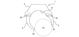
- Figs. 5A to 5C are schematic diagrams for explaining the state of the change in posture of the first arm 3 and the second arm 4 due to the difference in thickness of the finger F.
- Fig. 5B the case where the ring-type device 1 is worn on each of a finger F1 of a first thickness (Fig. 5B), a finger F2 of a second thickness thicker than the first thickness (Fig. 5A), and a finger F3 of a third thickness thicker than the second thickness (Fig. 5C) will be described.
- Fig. 5B a finger F1 of a first thickness
- Fig. 5A a finger F2 of a second thickness thicker than the first thickness
- Fig. 5C a finger F3 of a third thickness thicker than the second thickness
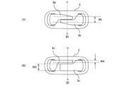
- FIG. 6A is a bottom view of the ring-type device 1 seen in the opposite direction to the arrow A in Fig. 1.
- Fig. 6B is a view similar to Fig. 6A, and the ring-type device 1 in Fig. 6A is a bottom view of a ring-type device 1 according to a modified example in which the width of the first arm 3 is changed.
- the first arm 3 and the second arm 4 are arranged so that their positions overlap each other in the insertion direction ID of the finger F relative to the attachment space FS. Furthermore, the lengths of the first arm 3 and the second arm 4 in the direction surrounding the attachment space FS from the main body 2 are such that their tip regions may interfere with each other depending on the thickness of the finger F to be attached. In other words, the tip of one of the first arm 3 and the second arm 4 when closest to the inner surface 21 of the main body 2 is configured to be closer to the rotation axis of the other arm than the tip of the other arm when closest to the inner surface 21.
- the first arm 3 and the second arm 4 are at a large angle relative to the main body 2 and do not interfere with each other.
- FIG. 5A to FIG. 5C when forming a wearing space FS corresponding to the fingers F1 to F3, the regions on the tip side of the first arm 3 and the second arm 4 interfere with each other. Therefore, the first arm 3 and the second arm 4 cannot both contact the fingers F1 to F3 at the same time, and one of the arms contacts the fingers F1 to F3, while the other arm urges the one arm against the fingers F1 to F3 (supports it from the back).
- the region including at least the tip of the other arm when it is closest to the inner surface 21 of the main body 2 is located outside the wearing space FS compared to the one arm when it is closest to the inner surface 21.
- the ring-type device of this embodiment is configured so that one arm part in contact with the finger F is supported from behind by the other arm part. Furthermore, the area where the other arm part contacts the one arm part, i.e., the area OR where the one arm part and the other arm part overlap each other when viewed in a direction perpendicular to the rotation axis of the one arm part or the rotation axis of the other arm part, is configured to be wider as the finger F becomes thinner. As shown in Figures 5A to 5C, the contact area between the one arm part and the other arm part becomes wider in the order of areas OR3, OR2, and OR1 from finger F3 to finger F1.
- the area over which the biasing force applied to the one arm part by the other arm part acts becomes wider, and the force with which the one arm part holds the finger F between the inner surface 21 of the main body 2 and the one arm part increases, resulting in a stable wearing state.
- the wearing space FS can be changed to a width corresponding to fingers F1 to F4 of various sizes (diameters), and the holding force acting on the finger F can be changed according to the thickness of the finger F.
- This allows the main body 2, first arm 3, and second arm 4 to be stably wrapped around the outer circumference of the finger F, even if the size of the finger F to be inserted varies.
- the ring-type device 1 is worn and held on the user's finger F in a stable position.
- the first arm 3 is located inside the second arm 4 and comes into direct contact with the finger F, and the second arm 4 supports the first arm 3 from behind, but the opposite configuration may also be used.
- the second arm 4 may be located inside the first arm 3 and comes into direct contact with the finger F, and the first arm 3 may support the second arm 4 from behind.
- the biasing force (spring constant of the torsion coil spring) for biasing the first arm 3 and the second arm 4 is preferably set to a magnitude that does not cause a misalignment between the finger F and the ring-type device 1 for a user with a thin finger F.
- the spring constant of the torsion coil spring may be set by adjusting the number of turns so that a biasing force of 10 N*mm or more is generated.
- the biasing force is too strong, pain may occur while wearing the device, so it is preferable to set the spring constant so that the load on the finger F is not large.
- the spring constant of the torsion coil spring may be set by adjusting the number of turns so that the biasing force is suppressed to 45 N*mm or less. Although it depends on the device configuration, it is preferably set to 15 N*mm or more and 30 N*mm or less. The range of the lower and upper limits of such biasing force may be found, for example, through experiments, and the spring constants of the torsion coil spring 32a and the torsion coil spring 42a may be set appropriately.
- biasing force biasing the first arm 3 (spring constant of the torsion coil spring 32a) and the biasing force biasing the second arm 4 (spring constant of the torsion coil spring 42a) may be set to be approximately equal.
- this is not limited to this, and for example, in cases where the arm portion that is on the inside and the arm portion that is on the outside of the mounting space FS are predetermined, a difference may be made between the biasing force acting on the inside arm portion and the biasing force acting on the outside arm portion to increase the stability of mounting.
- the arm on the outside of the mounting space FS may be made wider in the insertion direction ID than the arm on the inside, and the number of turns of the torsion coil spring may be increased accordingly to increase the biasing force compared to the inner arm.
- the inner diameter of the inner surface of the outer arm may be made larger than the inner diameter of the inner surface of the inner arm.
- the mounting space FS is configured to have a width that can accommodate a virtual circle of a predetermined diameter range (i.e., a finger of a thickness equivalent to the virtual circle) when viewed in the insertion direction ID.
- the width is a width that can accommodate a virtual circle of a diameter of 12.8 mm (a finger of a thickness equivalent to the virtual circle F1) to a virtual circle of a diameter of 25.4 mm (a finger of a thickness equivalent to the virtual circle F4), that is, a width of 12.8 mm or more and 25.4 mm or less.
- the basis for the change in the size of the virtual circle is the deepest part of the concave arc-shaped (concave curved) inner surface 21 of the main body 2.
- virtual circles of each size are arranged so as to pass through the point of the deepest part, and the spatial area corresponding to the size of the virtual circle is used as the basis for measuring the width of the mounting space FS.
- the width of the inner arm portion in contact with the finger F may be narrower than the width of the outer arm portion in the insertion direction ID of the finger F relative to the mounting space FS.
- the ring-shaped device 1 can be held in a different orientation.
- the side of the finger F facing the arm portion is the inner side (palm side) of the finger F, which is the side that is concave when the joint of the finger F is bent.
- the width W3 in the insertion direction ID of the first arm portion 3, which is the inner arm portion in contact with the finger F is narrower than the width W4 in the same direction of the second arm portion 4, which is the outer arm portion away from the finger F, making it easier to bend the finger F.
- the first arm 3 and the second arm 4 are configured so that the width in the insertion direction ID gradually narrows toward the tip.
- the width in the insertion direction ID of the tip surface of the arm that enters inside the mounting space FS is preferably 20 mm or less, or less than the width of the main body 2 in the insertion direction ID. Even more preferably, this width is 8 mm or less, which is suitable for storing the first arm 3 and the second arm 4 between the first and second joints of the finger F.
- the width in the insertion direction ID of the inner arm may be configured to fall within the above range.
- FIG. 7A is a schematic diagram of the first arm 3, and FIG. 7B is a cross-sectional view taken along the line C in FIG. 7A.
- first arm 3 will be described, but the second arm 4 is configured in the same way, so its description will be omitted.
- the inner surface 31 is the part of the first arm 3 that comes into contact with the finger F, and it is preferable that the surface of the inner surface 31 is particularly smooth.
- the first arm 3 may be made of two members, a first member 30a on the inner surface 31 side and a second member 30b on the opposite outer surface 34 side. With this configuration, when manufacturing the first arm 3 by combining multiple members, it is possible to position the parting line of the first member 30a and the second member 30b away from the inner surface 31, and it is possible to form the inner surface 31 smoothly.
- the parting line of the first member 30a and the second member 30b is located as close as possible to the outer surface 34 in order to more effectively prevent the finger F from getting caught. Since the inner surface 31 is a gently smooth concave surface, it is possible to prevent the finger F from getting caught when the finger F is inserted, and cleaning is also easy.
- the tip surface 33 (first tip surface) of the first arm 3 may be tapered to prevent the finger F from getting caught when the finger F and the ring-type device 1 rotate relative to each other. That is, the tip surface 33 of the first arm 3 has an inner distance (first inner distance) Li from the rotation axis (first rotation axis) 32x of the first arm 3 on the inner surface (first inner surface) 31 to the tip surface 33. Also, it has an outer distance (first outer distance) Lo from the rotation axis 32x on the outer surface (first outer surface) 34 to the tip surface 33.
- the tip surface 33 is inclined with respect to a virtual plane vp perpendicular to the extension direction of the first arm 3 so that the inner distance Li is shorter than the outer distance Lo.
- the inner surface 31 is configured so that both sides in the insertion direction ID have tapered surfaces ts1 and ts2 that are inclined symmetrically with respect to the insertion direction ID. This configuration prevents the finger F from getting caught on the inner surface 31, and smoothly guides the insertion and removal of the finger F into the mounting space FS.
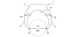
- each of the first arm 3 and the second arm 4 it is preferable to set the length of each of the first arm 3 and the second arm 4 from the main body 2 so that the ring-type device 1 does not slip off the finger F4 when the thickest finger F4 that is permitted to be worn is inserted.
- the gap Ws3 between the tip surface 33 and tip surface 44 of the first arm 3 and the second arm 4 when they are opened to their limit of movement is slightly larger than the maximum diameter of the thickest finger F4 that can be accommodated.
- first arm 3 and the second arm 4 have approximately the same length from the main body 2, but they may be different.
- the length of the first arm 3 is made shorter than the length of the second arm 4, and the range of rotation (maximum opening angle) of the first arm 3 relative to the main body 2 is made larger than that of the second arm 4.
- This makes it possible to guide the movement direction of the finger F to the side of the weaker biasing force when the finger F is removed from the attachment space FS, and control the second arm 4 to close before the first arm 3.
- the inner surface 21 of the main body 2 may be a concave surface in which multiple planes 21f1, 21f2 are connected at gradually changing angles.
- the inner surface 21 of the main body 2, the inner surface 31 of the first arm 3, and the inner surface 41 of the second arm 4 are each configured as a concave surface with a curvature corresponding to the maximum diameter of the thickest finger F4, but this configuration is not limited to this.
- the concave surface may be configured by planes 21f1, 21f2 that include a tangent to a virtual circle (virtual cylindrical surface) corresponding to the maximum diameter of the thickest finger F4.
- the center FC of the imaginary circle corresponding to the finger Fb with the smallest diameter that fits in the mounting space FS to be located on the imaginary line vl that passes through the center of rotation of the first arm 3 and the center of rotation of the second arm 4, or on the main body 2 side of the imaginary line vl. Furthermore, it is preferable to provide a third finger rest 213 and a fourth finger rest 214 on which the fingers Fa and Fc on either side of the finger Fb can be placed on the outside of the first arm 3 and the second arm 4, respectively. With this configuration, in the third mounting mode shown in Figure 4C, the first arm 3 and the second arm 4 are prevented from interfering with the gripping of the fingers.
- a restricting portion 29 is provided on the inside of the exterior 20 of the main body 2.
- the restricting portion 29 is provided so as to be able to come into contact with the outer surface 34 around the rotation axis 32 of the first arm 3 in order to restrict the maximum rotation angle (rotation range) of the first arm 3.
- the exterior 20 is a member that requires strength in the device configuration, and as part of it, a restricting portion 29 that restricts the rotation of the first arm 3 is provided. By improving the strength of the device and suppressing the occurrence of damage during long-term use, a longer life can be achieved.
- Such a rotation restricting configuration is similarly provided for the second arm 4.
- the described range of rotation may be the same for the first arm 3 and the second arm 4, or may be different.
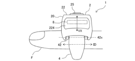
- Fig. 14 is a schematic front view of the finger ring device 1 according to this embodiment for explaining the arrangement of the vibration elements 8.
- Fig. 15A is a schematic front view of the finger ring device 1b according to Comparative Example 1.
- Fig. 15B is a schematic side view of the finger ring device 1c according to Comparative Example 2.
- Fig. 16A is a schematic cross-sectional view (cross-section perpendicular to the insertion direction ID) of the vibration element 8 and its periphery in the finger ring device 1 according to this embodiment.
- FIG. 16B is a schematic cross-sectional view as viewed from the arrow D in Fig. 16A.
- Fig. 16C is a schematic partial cross-sectional view of the finger ring device 1 according to this embodiment showing the state when the power source 11 is expanded.
- Fig. 17 is a side view of the finger ring device 1 according to this embodiment for explaining the arrangement of the vibration elements 8.
- the way in which the vibrations generated by the vibration element 8 are transmitted to the user may differ depending on the arrangement of the vibration element 8 in the ring-type device 1.
- the vibrations of the vibration element 8 may not be transmitted well to the finger on which the ring-type device 1 is worn, and the user may not be able to experience the desired sensory experience.
- the ring-type device is configured to allow various ways of wearing it on the finger, it is possible that differences in the way the device is worn (for example, when the finger on which it is worn is changed) may result in differences in how the user perceives the vibrations.
- the vibration element 8 is the component that consumes the most power among the components mounted on the ring-type device 1, and is required to vibrate efficiently with as little power as possible. It is difficult to mount a large-capacity battery on the ring-type device 1, so it is necessary to transmit vibrations efficiently with a small amount of power. On the other hand, unless the vibrations are of a certain magnitude, they may be difficult for the user to sense.
- the placement of the vibration element 8 must take into consideration the effect of vibration on the operation of other built-in devices.
- the ring-type device 1 of this embodiment is equipped with an inertial sensor 71, and depending on the placement of the vibration element 8, vibrations may be transmitted to the inertial sensor 71, causing erroneous detection.
- the vibration elements 8 are provided in a predetermined arrangement so that a user wearing the ring-type device 1 can more reliably sense the vibration of the vibration elements 8. Specifically, the vibration elements 8 are arranged so that the vibration direction is toward the finger inserted into the wearing space FS.
- an arrangement in which the vibration direction of the vibration element 8 is toward the finger inserted in the mounting space FS can be such that a virtual line VL passing through the vibration element 8 along the vibration axis VX of the vibration element 8 passes through the mounting space FS. That is, the virtual line VL passes through the inner surface and the outer surface opposite the inner surface of the ring-shaped body surrounding the mounting space FS, which is composed of the main body 2, the first arm 3 connected to one end of the main body 2, and the second arm 4 connected to the other end of the main body 2.
- the virtual line VL passes through the inner surface 21 of the exterior 20 of the main body 2 and the inner surface 31 of the first arm 3 as the inner surfaces of the ring-shaped body, and passes through the outer surface 22 of the exterior 20 of the main body 2 and the outer surface opposite the inner surface 31 of the first arm 3 as the outer surfaces of the ring-shaped body.
- One end of the vibration element 8 in the direction in which the vibration axis VX extends is located closer to the inner surface 21 of the exterior 20 of the main body 2, which is the inner surface of the annular body, and the other end is located closer to the outer surface 22 of the exterior 20 of the main body 2, which is the outer surface of the annular body.
- Fingers of various sizes can be worn in the wearing space FS, but it is preferable to position the vibration element 8 so that the vibration of the vibration element 8 can be reliably sensed by the user regardless of the size of the finger worn. Therefore, in this embodiment, the virtual line VL is positioned so that it passes through the center F2C of the virtual circular cross section corresponding to finger F2 as the reference center position of the finger inserted into the wearing space FS. In this embodiment, the center F2C is used as the center position at which the vibration of the vibration element 8 can be sensed by the user even when a finger F1 smaller than finger F2 is worn, or when fingers F3 and F4 larger than finger F2 are worn.
- the reference center position of the mounting space FS for determining the vibration direction of the vibration element 8 is not limited to the center F2C described above, and may be determined appropriately depending on the configuration of the device.
- the center position of a virtual circular cross section corresponding to a finger of average size within the range of finger sizes that can be inserted into the mounting space FS may be used as the reference center position for determining the vibration direction of the vibration element 8.
- the center of curvature of the concave arc surface that constitutes the inner surface 21 may be used as the reference center position.
- the vibration element 8 it is preferable to arrange the vibration element 8 so that the above-mentioned virtual line VL passes near the deepest part of the concave inner surface 21.
- the deepest part of the inner surface 21 can be the part where fingers F1 to F4 of all sizes come into contact with the exterior 20.
- the vibration element 8 is a so-called linear vibration actuator. That is, the vibration element 8 is equipped with a mover that is equipped with a magnet and supported by a shaft and a spring so that it can reciprocate in a predetermined axial direction, and a coil to which a current can be applied from the outside.
- the mover is integrally provided with a weight, and reciprocates against the spring force in a predetermined axial direction (vibration axis direction) along the shaft due to excitation of the coil by application of a current and the magnetic force of the magnet provided in the mover. This reciprocating movement of the mover generates vibration in a predetermined vibration direction in the vibration element 8.
- an axis passing through the center of the mover parallel to the axial direction of the shaft may be set as the vibration axis VX, and the direction along the vibration axis VX may be set as the vibration direction of the vibration element 8.
- the ring-type device 1 of this embodiment can be used in a wearing state in which it is held between a finger inserted into the wearing space FS and another finger, as shown in Figures 4A to 4C. Therefore, by generating vibrations of the vibration element 8 along the finger touching the ring-type device 1 (particularly the exterior 20) and the alignment of the fingers, it is possible to make the vibrations more easily perceptible by the user. Therefore, for example, it is preferable to position the vibration element 8 so that the above-mentioned virtual line VL passes through at least one of the first finger placement portion 223 and the second finger placement portion 224 of the exterior 20.
- the vibration element 8 (or the second finger rest portion 224) is positioned so that the virtual line VL passes through the second finger rest portion 224. This allows the vibration element 8 to be positioned between the finger F2 inserted into the mounting space FS and the finger Fn placed on the second finger rest portion 224, and allows vibrations to be efficiently and effectively transmitted to each of the fingers F2 and Fn.
- the vibration element 8 is arranged so that the virtual line VL passes through the area of the inner surface 21 that is particularly in contact with the finger inserted into the mounting space FS and the area of the second finger rest portion 224 that is particularly in contact with the finger placed on the second finger rest portion 224.
- the concave shape of the inner surface 21 and the outer peripheral shape of the finger inserted into the mounting space FS usually do not completely match, and the outer peripheral shape of the finger does not necessarily contact all areas of the inner surface 21.
- the concave shape of the second finger rest portion 224 and the outer peripheral shape of the finger placed on the second finger rest portion 224 usually do not completely match, and the outer peripheral shape of the finger does not necessarily contact all areas of the second finger rest portion 224.
- the vibration element 8 by arranging the vibration element 8 so that the virtual line VL passes through the above-mentioned area of the inner surface 21 and the center of the finger inserted into the mounting space FS, it is possible to efficiently and effectively transmit vibration to the finger inserted into the mounting space FS.
- the vibration element 8 by positioning the vibration element 8 so that the virtual line VL passes through the above-mentioned area of the second finger rest section 224 and also passes through the center of the finger placed on the second finger rest section 224, it becomes possible to transmit vibrations efficiently and effectively to the finger placed on the second finger rest section 224.
- the touch sensor 5 may be arranged at a position that is off the above-mentioned virtual line VL that passes through the vibration element 8 if there is concern that an erroneous operation may occur due to the vibration of the vibration element 8.
- the touch sensor 5 is arranged at a predetermined distance from the vibration element 8 in the circumferential direction around the center F2C of the virtual circle corresponding to the finger F2 as the center of the mounting space FS.
- the ring-type device 1b according to Comparative Example 1 shown in FIG. 15A has a different arrangement of the vibration element 8 from the ring-type device 1 according to this embodiment.
- the vibration axis VX of the vibration element 8 is perpendicular to the vibration axis VX of the vibration element 8 in the ring-type device 1 and perpendicular to the finger insertion direction ID into the wearing space FS. Therefore, in Comparative Example 1, the imaginary line VL passing through the vibration element 8 along the vibration axis VX does not pass through the wearing space FS, and there is a concern that the vibration of the vibration element 8 may not be sufficiently transmitted to the finger wearing the ring-type device 1b.
- the vibration direction of the vibration element 8 is along the circumferential direction surrounding the finger, and so there is concern that the vibration of the vibration element 8 will act to cause relative movement in the circumferential direction between the ring-type device 1b and the finger inserted in the wearing space FS. In other words, there is concern that the vibration of the vibration element 8 will cause the ring-type device 1b to rotate relative to the finger (the wearing position of the ring-type device 1b will shift in a direction around the outer circumference of the finger).
- the ring-type device 1c of Comparative Example 2 shown in FIG. 15B has a different arrangement of the vibration element 8 from that of the ring-type device 1 of this embodiment. Specifically, in the ring-type device 1c, the vibration axis VX of the vibration element 8 is perpendicular to the vibration axis VX of the vibration element 8 in the ring-type device 1 of this embodiment and is along the finger insertion direction ID into the wearing space FS.
- the vibration direction of the vibration element 8 is along the finger insertion direction ID relative to the wearing space FS, so there is a concern that the vibration of the vibration element 8 will act to move the ring-type device 1b and the finger inserted in the wearing space FS relative to each other in the insertion direction ID. In other words, there is a concern that the vibration of the vibration element 8 will move the ring-type device 1c in the insertion direction ID relative to the finger (shift the wearing position of the ring-type device 1b relative to the finger in the insertion direction ID).
- the ring-type device 1 according to this embodiment makes it possible to effectively transmit the vibration of the vibration element 8 to the finger on which the ring-type device 1 is worn. Furthermore, with the ring-type device 1 according to this embodiment, there is no concern that the vibration of the vibration element 8 will affect the wearing state of the ring-type device 1 on the finger, as in Comparative Examples 1 and 2, and a stable wearing state can be obtained.
- the vibration element 8 is preferably disposed in the vicinity of a portion of the exterior 20 that forms the outer surface 22 on which the first and second finger rests 223, 224, the button switch 6, and the touch sensor 5 are disposed, and preferably so as to be in contact with this portion.
- the exterior 20 is composed of an inner exterior 210 as a first housing and an outer exterior 220 as a second housing.
- the inner exterior 210 has an inner surface 21 that forms the mounting space FS.
- the outer exterior 220 has an outer surface 22 on which the first and second finger rests 223, 224, the button switch 6, the touch sensor 5, etc. are arranged.
- the inner exterior 210 and the outer exterior 220 are joined to each other by screws or the like, and form between them a substantially arc-shaped accommodation space (the internal space of the exterior 20) that accommodates built-in devices such as the inertial sensor 71, the geomagnetic sensor 72, the vibration element 8, the communication unit 9, the control unit 10, and the power source 11.
- the vibration element 8 is attached to the attachment portion 208 provided on the inner surface of the outer exterior 220 that forms the above-mentioned storage space of the exterior 20. Since the vibration of the vibration element 8 is directly transmitted to the outer exterior 220, the vibration is easily transmitted to the first and second finger rests 223, 224 provided on the outer exterior 220, the button switch 6, the touch sensor 5, etc.
- the inner surface of the inner exterior 210 that forms the above-mentioned storage space of the exterior 20 is provided with a mounting section 201 on which a control board 111 having a control IC mounted thereon as the control unit 10 is mounted, and a mounting section 211 on which the communication unit 9 and the power source 11 are mounted.
- the inner surface of the inner exterior 210 is further provided with mounting sections on which boards having an inertial sensor 71 and a geomagnetic sensor 72 are mounted.
- the vibration element 8 is arranged within the above-mentioned storage space of the exterior 20, separate from the other built-in devices (installed away from the board on which the other built-in devices are mounted).
- the operation of the vibration element 8 (application of current to the coil) is controlled by a control signal from the control unit 10, but the vibration element 8 is provided separately from the board 111 on which the control unit 10 is mounted, and is connected to the board 111 by a flexible cable 18.
- the vibration element 8 is also separated from the other boards attached to the inner exterior 210 of the exterior 20. This prevents the vibration of the vibration element 8 from being directly transmitted to the various devices provided on the inner exterior 210.
- the mounting portion 208 may be extended to a position closer to the inner exterior 210, and the vibration element 8 may be positioned closer to the inner surface 21 than the outer surface 22.
- the mounting section 211 to which the communication section 9 and the power source 11 are mounted is configured to form a gap space ES as a shared space for the communication section 9 and the power source 11.
- the communication section 9 includes a wireless module 90, a wireless antenna 91, and a wireless board 92 on which these are mounted.
- the power source 11 is a lithium ion battery, which has the property of expanding in the event of an abnormality such as high temperature generation, and is provided with, for example, a gas vent valve for releasing gas when it expands.
- the power source 11 which is a lithium ion battery, requires space around it to allow expansion in the event of the above-mentioned abnormality.
- the mounting portion 211 is configured to support the wireless board 92 and the power source 11 so that a gap space ES is formed between the wireless board 92 of the communication unit 9 and the power source 11.
- this gap space ES provides space to allow for the above-mentioned expansion of the power source 11, and also provides space around the wireless antenna 91 to ensure sensitivity.
- the gap space ES is a space shared by the communication unit 9 and the power source 11, and by sharing the space required for the communication unit 9 and the power source 11, it is possible to reduce the space required for the exterior 20 and improve the freedom of layout of the internal space of the exterior 20.
- the vibration element 8 is arranged so that its longitudinal direction is aligned with the insertion direction ID of the finger F.
- the vibration element 8 provided in the ring-type device 1 of this embodiment has an approximately rectangular parallelepiped outer shape, and by aligning its longitudinal direction with the insertion direction ID of the finger F, it can be arranged so that it does not take up space in the circumferential direction in the approximately arc-shaped space inside the exterior 20. Therefore, it is possible to increase the design freedom in designing the shape of the exterior 20 to fit the outer circumference of the finger.
- the vibration element 8 is arranged so that the direction in which the vibration axis VX of the vibration element 8 extends is perpendicular to the finger insertion direction ID into the mounting space FS, but this does not necessarily have to be perpendicular.
- the direction may be an intersecting direction having a slight angle with respect to the perpendicular direction, as long as the vibration of the vibration element 8 can be sufficiently transmitted to the finger inserted into the mounting space FS or the finger placed on the first and second finger rest portions 223, 224, etc.
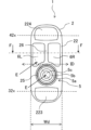
- the built-in devices such as the communication unit 9, control unit 10, power source 11, inertial sensor 71, and geomagnetic sensor 72, except for the vibration element 8, are attached to the inner exterior 210. Furthermore, the vibration element 8 and the other built-in devices are arranged inside the exterior 20, spaced apart from each other in the circumferential direction around the center F2C of a virtual circle corresponding to the finger F2, which is the center of the wearing space FS.
- an axis CX is parallel to a virtual line passing through the center of rotation (axis of rotation 32x) of the first arm 3 and the center of rotation (axis of rotation 42x) of the second arm 4, and passes through the center F2C as the reference center position.
- An axis CY is perpendicular to the axis CX and passes through the center F2C.
- the inertial sensor 71, the geomagnetic sensor 72, and the touch sensor 5 are located in the first quadrant
- the vibration element 8, the communication unit 9, and the power source 11 are located in the second quadrant
- the control unit 10 is located so as to straddle the first and second quadrants.
- the communication unit 9, the control unit 10, and the power source 11, which are included in the same second quadrant as the vibration element 8, are located in positions that do not overlap with the virtual line VL passing through the vibration element 8 in terms of the positional relationship in the circumferential direction around the center F2C (positions that are off the vibration element 8 when viewed in the vibration direction of the vibration element 8).
- the area where the first arm 3 and the second arm 4 open and close is around the border between the third and fourth quadrants in a coordinate system consisting of axes CX and CY, and is the area on the opposite side of axis CX from the area where the various built-in devices including the vibration element 8 are arranged.
- the first arm 3 and the second arm 4 hold the finger from the side opposite the vibration element 8 and push the finger from the third and fourth quadrants to the first and second quadrants, i.e., the main body 2 side, so that the vibration of the vibration element 8 is easily transmitted to the finger.
- the vibration element 8 in this embodiment is configured to operate by passing a current through the coil, and there is a concern that the magnetic force and magnetic field generated by passing a current through the coil may affect the operation of other built-in devices.
- the magnetic force and magnetic field generated by the vibration element 8 may be detected as noise by the inertial sensor 71 and the geomagnetic sensor 72.
- the communication unit 9 is composed of a wireless module 90 and a wireless antenna 91, but the magnetic force and magnetic field generated by the vibration element 8 may also become noise in the wireless antenna 91, and there is a concern that the metal material that constitutes the vibration element 8 may affect the sensitivity of the wireless antenna 91.
- the vibration of the vibration element 8 may cause erroneous operation of the touch sensor 5.
- the geomagnetic sensor 72 is spaced apart from the vibration element 8 so as to form an angle of at least 60 degrees, preferably 90 degrees, in the circumferential direction around the center F2C.
- the distance between the geomagnetic sensor 72 and the vibration element 8 may be determined, for example, by the shortest distance between the geomagnetic sensor 72 and the vibration element 8 in the circumferential direction around the center F2C.
- L72 be a virtual line passing through the center F2C and the portion of the geomagnetic sensor 72 that is closest to the vibration element 8 in the circumferential direction.
- L8a be a virtual line passing through the center F2C and the portion of the vibration element 8 that is closest to the geomagnetic sensor 72 in the circumferential direction.
- the geomagnetic sensor 72 and the vibration element 8 should be arranged so that the angle R1 that the virtual line L72 and the virtual line L8a make around the center F2C is within the above angle range.
- the inertial sensor 71 is spaced apart from the vibration element 8 so as to form an angle of at least 60 degrees, preferably 90 degrees, in the circumferential direction around the center F2C.
- the distance between the inertial sensor 71 and the vibration element 8 may be determined, like the geomagnetic sensor 72, by the shortest distance between the inertial sensor 71 and the vibration element 8 in the circumferential direction around the center F2C.
- L71 be a virtual line passing through the center F2C and the part of the inertial sensor 71 that is closest to the vibration element 8 in the circumferential direction.
- L8a be a virtual line passing through the center F2C and the part of the vibration element 8 that is closest to the inertial sensor 71 in the circumferential direction.
- the inertial sensor 71 and the vibration element 8 should be arranged so that the angle R2 between the virtual line L71 and the virtual line L8a around the center F2C is within the above angle range.
- the communication unit 9 is disposed so that the wireless antenna 91 forms an angle of at least 30 degrees, preferably 90 degrees, with respect to the vibration element 8 in the circumferential direction around the center F2C.
- the distance between the wireless antenna 91 and the vibration element 8 may be determined, for example, by the shortest distance between the wireless antenna 91 and the vibration element 8 in the circumferential direction around the center F2C.
- L91 be an imaginary line passing through the center F2C and the part of the wireless antenna 91 that is closest to the vibration element 8 in the circumferential direction.
- Let L8b be an imaginary line passing through the center F2C and the part of the vibration element 8 that is closest to the wireless antenna 91 in the circumferential direction.
- the wireless antenna 91 (communication unit 9) and the vibration element 8 should be disposed so that the angle R3 that the virtual line L91 and the virtual line L8b make around the center F2C is within the above angle range.
- the touch sensor 5 is spaced apart from the vibration element 8 so as to form an angle of at least 30 degrees, preferably 90 degrees, in the circumferential direction around the center F2C.
- the distance between the touch sensor 5 and the vibration element 8 may be determined, for example, by the shortest distance between the touch sensor 5 and the vibration element 8 in the circumferential direction around the center F2C.
- L5 be an imaginary line passing through the center F2C and the part of the touch sensor 5 that is closest to the vibration element 8 in the circumferential direction.
- L8a be an imaginary line passing through the center F2C and the part of the vibration element 8 that is closest to the touch sensor 5 in the circumferential direction.
- the touch sensor 5 and the vibration element 8 should be arranged so that the angle R4 that the imaginary line L5 and the imaginary line L8a make around the center F2C is within the above angle range.
- the center position of the mounting space FS for determining the circumferential separation distance between the vibration element 8 and the other built-in devices and the touch sensor 5, etc. is not limited to the center F2C described above, but may be determined appropriately depending on the configuration of the device.
- the center position of the imaginary circular cross section corresponding to a finger of average size within the range of finger sizes that can be inserted into the mounting space FS may be used as the reference.
- the center of curvature of the concave arc surface that constitutes the inner surface 21 may be used as the reference.
- vibration element 8 In addition, in this embodiment, an example has been described in which a so-called linear vibration actuator is used as the vibration element 8, but other vibration actuators may be used as the vibration element 8. For example, it may be a vibration actuator using a piezoelectric element, or a vibration actuator using an eccentric motor.
- the ring-type device 1 of this embodiment has an operated surface on the outer surface 22 of the exterior 20 of the main body 2, on which a touch sensor 5 and button switches 6R and 6L are provided as operated parts.
- the ring-type device 1 is assumed to be used in a manner in which the user performs various input operations without looking at the hand on which the ring-type device 1 is worn. In other words, the user grasps and identifies the touch sensor 5 and button switches 6R and 6L by relying on the feel of the finger touching the operated surface, and performs the desired input operation.
- the ring-type device 1 is required to be able to reliably grasp the positions of the touch sensor 5 and button switches 6R and 6L without looking at the operated surface, and to be able to smoothly operate the touch sensor 5 and button switches 6R and 6L without erroneous operation.
- the arrangement of the touch sensor 5 and the button switches 6R, 6L on the operated surface is as shown in Figs. 4A to 4C, with the touch sensor 5 being arranged on the wrist side of the hand wearing the ring-type device 1, and the button switches 6R, 6L being arranged on the fingertip side. That is, with respect to the finger inserted into the wearing space FS, the touch sensor 5 is arranged on the front side in the circumferential direction around the finger insertion direction, and the button switches 6R, 6L are arranged on the back side.
- the normally assumed operating mode is a mode in which a finger other than the thumb (typically the index finger or middle finger) is inserted into the wearing space FS, and the touch sensor 5 and the button switches 6R, 6L are operated by the thumb extending from the front side to the back side of the touch sensor 5.
- a finger other than the thumb typically the index finger or middle finger
- the touch sensor 5 and the button switches 6R, 6L are operated by the thumb extending from the front side to the back side of the touch sensor 5.
- Figs. 4A to 4C show the case where the ring-type device 1 is worn on the right hand, but the ring-type device 1 may also be worn on the left hand.
- the first finger rest 223 is a finger rest (first recess) located on the front side of the exterior 20 of the main body 2.
- the second finger rest 224 is a finger rest (second recess) located on the rear side of the exterior 20 of the main body 2.
- the index finger can be placed on the second finger rest 224.
- the ring-shaped device 1 This allows the ring-shaped device 1 to be held in such a way that a part of it is wrapped in the palm and the index finger presses down on the main body 2, thereby stabilizing the wearing posture of the ring-shaped device 1.
- the first finger rest 223 and the second finger rest 224 provide a place for the fingers to retreat when not operating, which prevents the fingers from unintentionally touching the operated part, leading to the prevention of erroneous operation.
- the width Wd of the main body 2 shown in FIG. 18 (the width of the main body 2 in the finger insertion direction ID relative to the wearing space FS) is set to approximately 25.0 mm. This setting corresponds to the distance between the joints of the finger inserted into the wearing space FS, or the width of the thumb that operates the touch sensor 5 and the button switches 6R and 6L.
- the ring-shaped device 1 of this embodiment is designed to be operated by the thumb, and has a touch sensor 5 and button switches 6R and 6L configured with a predetermined size, shape and layout, and is also provided with a first boundary identification rib 25 and a second boundary identification rib 26, which will be described later. Because the thumb is the widest finger on the human hand, it is necessary to provide a configuration that allows the touch sensor 5 and button switches 6R and 6L, which serve as the operated parts, with ease of pressing them apart, while not being able to be given a sufficient size.
- the ring-type device 1 of this embodiment has a first boundary identification rib 25 and a second boundary identification rib 26 as a configuration for allowing a user to recognize the distinction and arrangement of the touch sensor 5 and the button switches 6R, 6L only by the sensation of the finger touching the operated surface.
- the first boundary identification rib 25 as the first rib and the second boundary identification rib 26 as the second rib are configured as part of the exterior 20.
- the shapes and arrangements of the touch sensor 5 and the button switches 6R, 6L as the operated parts are also configured to be suitable for operation only by the tactile sense of the fingers.
- the first boundary identification rib 25 is an annular rib arranged to surround the outer periphery of the touch sensor 5.
- the first boundary identification rib 25 allows the user to recognize that the touch sensor 5 is inside it by tactilely touching the annular convex shape with a finger.
- the touch sensor 5 has a shape that protrudes higher than the first boundary identification rib 25. Therefore, by tactilely touching the finger that there is a convex portion inside the annular convex shape that protrudes further than the convex shape, the user can recognize that it is the touch sensor 5.
- annular first boundary identification rib 25 is disposed between the touch sensor 5 and the button switches 6R, 6L. Therefore, the positional relationship between the first boundary identification rib 25 and the second boundary identification rib 26 described below allows the user to recognize the boundary between the touch sensor 5 as the first operated part and the button switches 6R, 6L as the second operated part.
- the second boundary identification rib 26 is provided to extend circumferentially on the outer surface 22 of the exterior 20 of the main body 2 between the button switch 6R and the button switch 6L that are aligned in the finger insertion direction ID relative to the mounting space FS of the ring-type device 1.
- the second boundary identification rib 26 protrudes higher than the upper surfaces of the button switches 6R and 6L. Therefore, by tactilely feeling the convex shape extending in the circumferential direction of the finger (around the finger insertion direction) inserted into the mounting space FS, the user can recognize that the lower parts adjacent to both sides of the convex shape in the finger insertion direction ID are the button switches 6R and 6L.
- the second boundary identification rib 26 allows the user to recognize the boundary between the button switch 6R as the first operated part and the button switch 6L as the second operated part.
- the first boundary identification rib 25 is positioned on the front side of the second boundary identification rib 26 in the circumferential direction of the finger, and the pair of button switches 6R, 6L are positioned so as to be symmetrical with respect to the second boundary identification rib 26 in the finger insertion direction ID. It can be said that these configurations positioned around the second boundary identification rib 26 have the function of providing the user with a sense of certainty that the circumferentially extending convex shape felt by the finger is the second boundary identification rib 26.
- the annular convex shape of the first boundary identification rib 25 is a characteristic shape that can be recognized only by the feel of the finger, and is a shape that is easy for the user to recognize.
- the finger By using the finger to feel the presence of a convex shape extending in the circumferential direction behind the annular convex shape, the user can confidently recognize that the convex shape in the circumferential direction is the second boundary identification rib 26.
- the user can confidently recognize that the circumferential convex shape is the second boundary identification rib 26. Furthermore, the user can confidently recognize that of the symmetrical shapes on both sides in the finger insertion direction ID of the circumferential convex shape, the right side is button switch 6R and the left side is button switch 6L.
- Fig. 19 is a schematic cross-sectional view taken along the line E in Fig. 18, showing the height relationships among the touch sensor 5, the button switches 6R and 6L, the first boundary identification rib 25, etc.
- the height H5 of the touch sensor 5 is higher than the height H25 of the first boundary identification rib 25.
- the height H6 of the button switches 6L and 6R is equal to or higher than the height H22 of the outer surface 22 of the exterior 20 of the main body 2.
- the height H25 of the first boundary identification rib 25 is equal to or higher than the height H6 of the button switches 6L and 6R.
- the heights of the outer surface 22 of the exterior 20 of the main body 2, the touch sensor 5, the button switches 6R and 6L, and the first boundary identification rib 25 are configured to satisfy the relationship H22 ⁇ H6 ⁇ H25 ⁇ H5.
- the height difference (H25-H6) of the first boundary identification rib 25 relative to the button switches 6L, 6R is configured to be 0.3 mm or more.
- the width W25 of the first boundary identification rib 25 is configured to be 1.5 mm or more.
- the height H25 and width W25 of the first boundary identification rib 25 are set from the perspective of preventing erroneous operation during blind operation. If the height H25 is too low or the width W25 is too narrow, it may be difficult to identify the first boundary identification rib 25. Conversely, if the height H25 is too high or the width W25 is too wide, it may interfere with the operation of the touch sensor 5.
- the above-mentioned numerical ranges for each dimension are merely examples, and may be set to suitable numerical values from the perspective of operability depending on the configuration of the device.
- the first boundary identification rib 25 is disposed between the button switches 6R, 6L and the touch sensor 5, which prevents the touch sensor 5 from being unintentionally operated when the button switches 6R, 6L, which are push buttons, are pressed.
- the touch sensor 5 is a so-called optical pointing device, and is equipped with an optical sensor section 5c with a detection window provided in the center of the circular top surface 5b of the button section 5a. By moving a finger (moving it in a plane) over this optical sensor section 5c, a pointing operation, a flick operation, etc. can be performed.
- the touch sensor 5 is not limited to an optical pointing device, and may be, for example, a capacitive pointing device.
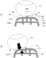
- the touch sensor 5 is also configured such that the button portion 5a can move up and down, and an input operation can be performed by pressing the circular upper surface 5b of the button portion 5a. That is, the button portion 5a is configured to be movable so that the amount of embedment in the first boundary identification rib 25 surrounding its outer periphery can be changed, and the circular upper surface 5b is pressed and sinks inside the annular first boundary identification rib 25 to form an input state.
- the button portion 5a is biased by a biasing means such as a spring (not shown) to be positioned at a height (home position) protruding from the first boundary identification rib 25 unless a particular external force is applied.
- the user can perform an input operation by pressing the circular upper surface 5b of the button portion 5a against the biasing force of the biasing means.
- the biasing force of the biasing means returns the button portion 5a to a height (home position) protruding from the first boundary identification rib 25.
- the height of the circular upper surface 5b of the button portion 5a which is used to set the input state by pressing it, is lower than the height of the first boundary identification rib 25. This makes it possible to configure the button portion 5a so that it does not easily enter the input state, even if the finger touches the button portion 5a while checking the first boundary identification rib 25 with a finger, for example. In other words, it is possible to suppress a malfunction that erroneously sets the button portion 5a to the input state.
- top 25a of the first boundary identification rib 25 and the optical sensor unit 5c there is an annular surface area on the circular upper surface 5b that surrounds the outer periphery of the optical sensor unit 5c, and an inclined area 25b that extends from the base of the first boundary identification rib 25 to the top 25a.
- This ensures a predetermined distance between the top 25a of the first boundary identification rib 25 and the optical sensor unit 5c. This also makes it possible to prevent the occurrence of a malfunction in which the movement of a finger to feel the above-mentioned first boundary identification rib 25 is detected as an input to the optical sensor unit 5c.
- the outer periphery of the circular upper surface 5b of the button portion 5a is configured to have an inclined surface 5d that tapers in diameter, and a distance is provided between the top 25a of the first boundary identification rib 25 and the circular upper surface 5b. This makes it possible to prevent the movement of the finger to feel the first boundary identification rib 25 from leading to the pressing operation of the button portion 5a of the touch sensor 5. In other words, the occurrence of erroneous operation can be prevented.
- 20A and 20B are schematic cross-sectional views taken along the line F in FIG. 18.
- the second boundary identification rib 26 protrudes outward (upward) from the top surface of each of the button switches 6R and 6L, and in this embodiment, the protruding height H26 is configured to be in the range of 0.3 mm or more and 1.0 mm or less.
- the width W26 of the second boundary identification rib 26 between the button switches 6R and 6L is configured to be in the range of 1.0 mm or more and 2.5 mm or less.
- the protruding height H26 and width W26 of the second boundary identification rib 26 are set from the perspective of preventing erroneous operation during blind operation. If the protruding height H26 is too low or the width W26 is too narrow, it may be difficult to identify the second boundary identification rib 26. Conversely, if the protruding height H26 is too high or the width W26 is too wide, it may interfere with the pressing of the button switches 6R, 6L.
- the above-mentioned numerical ranges for each dimension are merely examples, and may be set to suitable numerical values from the perspective of operability depending on the configuration of the device.
- the button switches 6R, 6L have curved (convex arc-shaped) ends 6cR, 6cL on the outside of the flat portions 6pR, 6pL in the finger insertion direction ID.
- the ends 6cR, 6cL are located upstream (radially outward from the reference center of the mounting space FS) of the corners 20eR, 20eL between the outer peripheral surface and the side surface of the exterior 20 of the main body 2 in the pressing direction of the button switches 6R, 6L.
- the ends 6cR, 6cL of the button switches 6R, 6L are configured to form part of the corner between the outer periphery and the side of the main body 2.
- the button switches 6R, 6L can be pressed with the image of pressing a corner of a roughly arc-shaped structure including the exterior 20 of the main body 2 and the button switches 6R, 6L.
- the button switches 6R, 6L can be easily pressed even on a small-sized main body 2.
- the corners of the structure have a shape that is easily detected by the tactile sense of the fingers, and by configuring the pressing operation to be performed by relying on the tactile sense of the corners, operability can be improved.
- ends 6cR, 6cL are ends having curved surfaces relative to the flat portions 6pR, 6pL, but they may also be corners formed with straight surfaces.
- ⁇ Dimensional Relationship Between Touch Sensor 5 and Button Switches 6R, 6L, etc.>> 21 is a top view showing the configuration of the operated surface of the finger ring type device 1, and is a diagram explaining the shapes and arrangement of the touch sensor 5 and the button switches 6R and 6L.
- the sizes and arrangement of the button switches 6R and 6L are defined by various dimensions based on the center 5e (center of the annular shape of the first boundary identification rib 25) of the touch sensor 5 (optical sensor unit 5c) when the operation surface of the main body 2 is viewed in plan.
- the width BD of the combined button switch 6R and button switch 6L in the finger insertion direction ID is configured to be 25.0 mm or less, preferably 10.0 mm or less.
- the shortest distance SD between the touch sensor 5 and the button switches 6R, 6L is configured to be 1.5 mm or more, and the longest distance LD is configured to be 20.0 mm or less.
- these numerical ranges are suitable for the ring-type device 1 of this embodiment. In other words, these are merely examples, and may be set appropriately so that the amount of finger movement between the touch sensor 5 and the button switches 6R, 6L is as small as possible, while still remaining within a reasonable range for the amount of finger movement used for operation.
- the width DD of the button switches 6R, 6L in the circumferential direction of the main body 2 is configured to be 8.0 mm or more even in the narrowest area.
- the size and shape of the button switches 6R, 6L are preferably configured so that when used by a person with large fingers, the button switches 6R, 6L can be comfortably pressed with the pad of the thumb when the finger is inserted up to the base into the attachment space FS. Note that the above numerical ranges are merely examples and may be set as appropriate depending on the device configuration.
- the first finger rest section 223 and the second finger rest section 224 are formed as concave curved surfaces, but may be formed as flat surfaces, and are configured so that at least one of the width in the finger insertion direction ID and the width in the circumferential direction of the main body 2 is 10.0 mm or greater.
- the ring-type device 1d has a configuration for preventing the user from wearing the ring-type device 1d with the front side and the back side reversed.
- the ring-type device 1d has a protrusion 22e4 as a configuration for giving the user an uncomfortable feeling when the device is worn incorrectly.
- the protrusion 22e is the back end of the operated surface 22o on which the touch sensor 5 and the button switches 6R and 6L are arranged in the circumferential direction of the main body 2, and is provided between the operated surface 22o and the second finger rest 224.
- the front end of the operated surface 22o on the opposite side, that is, between the operated surface 22o and the first finger rest 223, is a flat portion 22e3. In other words, the back end and the front end of the operated surface 22o are asymmetrically configured.
- the configuration for giving the user a sense of discomfort when the device is worn incorrectly is not limited to the protrusion 22e described above.
- the first finger rest portion 223 and the second finger rest portion 224 may be made to have different shapes to give the user a sense of discomfort. For example, by making the first finger rest portion 223 concave and the second finger rest portion 224 flat, the user will feel that the thumb does not fit properly, even though it would be stable when the device is worn correctly, and this will make the user aware of the incorrect wear.
- control unit 10 may be configured to process the input to the touch sensor 5 and button switches 6R and 6L so that the input signals are inverted vertically and horizontally.
- FIG. 23A is a schematic front view of the ring-type device 1 of this embodiment, showing the state when the user is pressing the button switches 6R and 6L with the finger FO.
- FIG. 23B is a schematic front view of the ring-type device 1 of this embodiment, showing the state when the user is pressing the touch sensor 5 with the finger FO.
- a virtual line along the operated surface 22o (the surface on which the touch sensor 5 and the button switches 6R and 6L are aligned in the circumferential direction of the main body 2) of the outer surface 22 of the exterior 20 of the main body 2 is defined as AL.
- a virtual line (virtual reference line) that passes through the deepest part P of the inner surface 21 of the exterior 20 of the main body 2 and is perpendicular to the virtual line AL is defined as FL.
- the ring-shaped device 1 of this embodiment is configured such that the touch sensor 5 and the button switches 6R and 6L aligned in the circumferential direction of the main body 2 are arranged on opposite sides of the virtual line FL (symmetrical in the circumferential direction with respect to the virtual line FL). That is, the touch sensor 5 is located on the front side of the main body 2 (one side, first side) with respect to the virtual line FL, and the button switches 6R and 6L are located on the back side of the main body 2 (the other side, second side) with respect to the virtual line FL.
- the deepest part P of the inner surface 21 for determining the virtual line FL may be defined as the position where the finger FI inserted into the mounting space FS always comes into contact with the inner surface 21.
- the virtual line FL may be a virtual line that passes through the reference center F2C of the finger inserted into the mounting space FS and is perpendicular to the virtual line AL.
- the deepest part P may be defined as a position included in an area of the inner surface 21 that is located opposite the area where the first arm 3 and the second arm 4 overlap with each other, relative to the reference center F2C of the finger inserted into the mounting space FS.
- the touch sensor 5 as the first operated part and the button switches 6R and 6L as the second operated part are arranged in the circumferential direction of the main body 2. Therefore, the force that the touch sensor 5 receives from the finger FO when pressed down may include a component force that generates a moment with respect to the main body 2, with the contact area of the finger FI and the inner surface 21 including the deepest part P as the base point. Similarly, the force that the button switches 6R and 6L receive from the finger FO when pressed down may include a component force that generates a moment with respect to the main body 2, with the contact area of the finger FI and the inner surface 21 including the deepest part P as the base point.
- Such a moment may inevitably occur due to the layout in which the touch sensor 5 and the button switches 6R and 6L are arranged in the circumferential direction of the main body 2.
- the touch sensor 5 and the button switches 6R and 6L which are arranged close to each other in the circumferential direction of the main body 2, on opposite sides of the virtual line FL, it is possible to minimize the magnitude of the generated moment.
- FIG. 24A is a schematic front view of the ring-type device 1e of Comparative Example 3, showing the state when the user is pressing the button switches 6R and 6L with the finger FO.
- FIG. 24B is a schematic front view of the ring-type device 1e of Comparative Example 3, showing the state when the user is pressing the touch sensor 5 with the finger FO.
- the ring-type device 1e of Comparative Example 3 is configured such that the touch sensor 5 and button switches 6R, 6L are arranged so that the touch sensor 5 overlaps the imaginary line FL when viewed in the finger insertion direction ID.
- the touch sensor 5 and button switches 6R, 6L which are aligned in the circumferential direction of the main body 2, are arranged toward the rear in the circumferential direction of the main body 2 (biased toward the rear relative to the imaginary line FL).
- the button switches 6R, 6L are positioned away from the finger FO in the circumferential direction toward the rear. Due to the layout in which the finger FO approaches the button switches 6R, 6L from the front side toward the rear side in the circumferential direction, the direction of the pressing force of the finger FO when pressing the button switches 6R, 6L approaches the direction from the front side toward the rear side in the circumferential direction. This increases the magnitude of the moment described above generated in the main body 2, making it easier to generate a force that rotates the ring-shaped device 1e with respect to the finger FI inserted in the wearing space FS.
- FIG. 25A is a schematic front view of the ring-type device 1f of Comparative Example 4, showing the state when the user is pressing the button switches 6R and 6L with the finger FO.
- FIG. 25B is a schematic front view of the ring-type device 1f of Comparative Example 4, showing the state when the user is pressing the touch sensor 5 with the finger FO.
- the ring-type device 1f of Comparative Example 4 is configured such that the touch sensor 5 and button switches 6R, 6L are arranged so that the button switches 6R, 6L overlap the imaginary line FL when viewed in the finger insertion direction ID.
- the touch sensor 5 and button switches 6R, 6L which are aligned in the circumferential direction of the main body 2, are arranged closer to the front in the circumferential direction of the main body 2 (biased toward the front with respect to the imaginary line FL).
- the finger FO particularly when the finger FO is the thumb, approaches the touch sensor 5 and the button switches 6R and 6L from the front side toward the back side in the circumferential direction of the main body 2. Therefore, the direction of the pressing force of the finger FO tends to include an angle from the front side toward the back side, and therefore, regardless of whether the touch sensor 5 or the button switches 6R and 6L are pressed, the magnitude of the generated moment can be kept small.
- the ring-type device 1 of this embodiment makes it possible to stabilize the state in which the ring-type device 1 is attached to the finger FI, and also makes it possible to obtain stable operability without forcing the finger FO to assume an unnatural posture during a pressing operation.
- the second boundary identification rib 26 is a single rib that extends continuously in the circumferential direction of the finger, but is not limited to this configuration.
- it may be a rib that is divided in the circumferential direction, that is, a configuration in which multiple ribs each extending in the circumferential direction are continuously lined up in the circumferential direction.
- it may be a configuration in which multiple protrusions are continuously lined up in the circumferential direction.
- the first boundary identification rib 25 is a single rib formed in a continuous annular shape, but is not limited to this configuration.
- the rib instead of a completely closed annular shape, the rib may be approximately C-shaped, with a portion of the circle interrupted.
- the rib may be configured such that multiple ribs each extending on an arc are continuously arranged in an annular shape.
- the rib may be configured such that multiple protrusions are continuously arranged in an annular shape.
- the annular shape is not limited to a perfect circle as in this embodiment, but may be an ellipse.
- the shape may be a polygon rather than a circle.
- the first arm 3b closest to the inner surface 21 of the main body 2 and the second arm 4b closest to the inner surface 21 have an overlapping area when viewed in the direction of the rotation axis 32x of the first arm 3b or the rotation axis 42x of the second arm 4b.
- the tip sides of the first arm 3b and the second arm 4b are offset from each other in the insertion direction ID.
- the first arm 3b and the second arm 4b are both worn in contact with the finger F.
- the overlapping area between one arm and the other arm becomes gradually wider in the order of areas OR3, OR2, and OR1 when viewed in the direction along the insertion direction ID or the rotation axes 32x, 42x.
- the first arm 3b and the second arm 4b are arranged alternately in the insertion direction ID, so that the size of the external shape of the ring-type device 1g in the direction perpendicular to the insertion direction ID is compressed compared to that of the ring-type device 1 of embodiment 1, improving the ease of gripping when worn on the finger F.
- the first arm 3b and the second arm 4b may be configured to have a shape that is approximately symmetrical in the insertion direction ID. Furthermore, as shown in FIG. 27A, the first arm 3b and the second arm 4b are configured so that the width in the insertion direction ID gradually narrows as they approach the tip. With this configuration, for example, in the third wearing mode shown in FIG. 4C, the first arm 3b and the second arm 4b are prevented from interfering with the gripping of the fingers.
- the distance Wt from the outer end of the tip surface of the first arm 3b to the outer end of the tip surface of the second arm 4b in the insertion direction ID is preferably 20 mm or less, or less than the width of the main body 2 in the insertion direction ID. Even more preferably, the distance Wt is 8 mm or less, which is suitable for placing the first arm 3b and the second arm 4b between the first and second joints of the finger F.
- the width in the insertion direction ID may be different between the first arm 3c and the second arm 4c. That is, the width W3 in the insertion direction ID at the tip end portion of the first arm 3c is configured to be larger than the width W4 in the insertion direction ID at the tip end portion of the second arm 4c.
- the above width may be set according to the difference between the biasing force of the torsion coil spring 32s and the biasing force of the torsion coil spring 42s so that the force with which the first arm 3c biases the finger F and the force with which the second arm 4c biases the finger F are uniform.
- the first arm 3d and the second arm 4d may be arranged in a staggered comb-like configuration in the insertion direction ID. That is, the second arm 4d has a pair of first and second arm portions 4d1 and 4d2, and the first arm 3d is arranged between the first and second arm portions 4d1 and 4d2 in the insertion direction ID.
- the combined configuration of the first arm 3d and the second arm 4d is symmetrical with respect to the insertion direction ID, and the finger F can be inserted into the mounting space FS in the same way from either the left or right side in the insertion/removal direction ID. That is, when mounting the ring-type device 1g on the finger F, there is no need to worry about the insertion direction, and mounting ease can be improved.
- the disclosure of the embodiments of the present invention includes the following configurations.
- (Configuration 1) A ring-type device that is worn on a user's finger, An annular body surrounding the mounting space; A vibration element provided inside the annular body; A control unit that controls the vibration element; Equipped with A ring-shaped device, characterized in that a virtual line passing through the vibration element along the vibration axis of the vibration element passes through the wearing space.
- (Configuration 2) The finger ring type device described in configuration 1, characterized in that the imaginary line passes through the inner surface of the annular body forming the wearing space and the outer surface of the annular body opposite the inner surface.
- (Configuration 3) A ring-type device that is worn on a user's finger, An annular body surrounding the mounting space; A vibration element provided inside the annular body; A control unit that controls the vibration element; Equipped with The vibration element is arranged to have a vibration axis that passes through the vibration element, and the vibration axis of the vibration element is arranged to pass through the mounting space.
- the vibration element is arranged such that the vibration axis of the vibration element extends along a direction in which the vibration axis of the vibration element extends, and the one end of the vibration element is located on a side close to an inner surface of the annular body that defines the mounting space.
- a ring-shaped device characterized in that the other end of the vibration element in the direction in which the vibration axis extends is located on the side closer to the outer surface of the annular body, opposite the inner surface.
- a ring-type device described in any one of configurations 1 to 3 characterized in that the direction in which the vibration axis extends is a direction that intersects with the direction in which the finger is inserted into the wearing space.
- Configuration 5) A finger ring-type device described in any one of configurations 1 to 4, characterized in that the vibration element is provided inside the annular body, closer to the inner surface than the outer surface opposite the inner surface of the annular body that forms the wearing space.
- (Configuration 6) A ring-type device described in any one of configurations 1 to 5, characterized in that the longitudinal direction of the vibration element is along the direction in which the finger is inserted into the wearing space.
- the annular body has a contact portion on an outer surface opposite to an inner surface that defines the mounting space, the contact portion being contacted by a finger different from the finger inserted into the mounting space;
- (Configuration 8) The finger ring type device according to configuration 7, wherein the annular body has an operating member provided in a part of the contacted portion.
- (Configuration 9) The finger ring type device according to configuration 8, wherein the virtual line does not pass through the operating member.
- (Configuration 10) A finger ring-type device described in any one of configurations 1 to 4, characterized in that the vibration element is provided inside the annular body, closer to the outer surface than the inner surface.
- (Configuration 11) Further comprising a geomagnetic sensor provided inside the annular body, A finger ring device described in any one of configurations 1 to 10, characterized in that a virtual line passing through the vibration element along the vibration axis does not pass through the geomagnetic sensor.
- (Configuration 12) The finger ring device of configuration 11, wherein the vibration element is provided at a distance from a substrate on which the geomagnetic sensor is mounted.
- a finger ring device as described in configuration 11 or 12, characterized in that the vibration element and the geomagnetic sensor are separated from each other so that the angle between the vibration element and the geomagnetic sensor in the circumferential direction around the reference center of the wearing space is at least 60 degrees, preferably 90 degrees or more.
- a finger ring type device described in any one of configurations 1 to 13, characterized in that a virtual line passing through the vibration element along the vibration axis does not pass through the inertial sensor.
- a control board on which the control unit is mounted is provided inside the annular body, A finger ring type device described in any one of configurations 1 to 16, characterized in that a virtual line passing through the vibration element along the vibration axis does not pass through the control board.
- the antenna further includes a radio antenna disposed inside the annular body.
- (Configuration 20) When viewed in the direction of finger insertion into the mounting space, The finger ring device of configuration 19, characterized in that the vibration element and the wireless antenna are spaced apart so that the angle between the vibration element and the wireless antenna in the circumferential direction around the reference center of the wearing space is at least 30 degrees, preferably 90 degrees or more.
- (Configuration 21) Further comprising a lithium ion battery disposed inside the annular body; a gap is provided between the wireless antenna and the lithium ion battery; The finger ring device of configuration 19 or 20, characterized in that the gap provides space for ensuring the sensitivity of the wireless antenna and space for allowing expansion of the lithium ion battery.
- the annular body is The main body, A first arm portion connected to one end side of the main body; A second arm portion connected to the other end side of the main body; Has The vibration element is provided inside the main body, A ring-type device described in any one of configurations 1 to 21, characterized in that a virtual line passing through the vibration element along the vibration axis passes through at least one of the first arm portion and the second arm portion.
Landscapes
- Engineering & Computer Science (AREA)
- General Engineering & Computer Science (AREA)
- Theoretical Computer Science (AREA)
- Human Computer Interaction (AREA)
- Physics & Mathematics (AREA)
- General Physics & Mathematics (AREA)
- Adornments (AREA)
- User Interface Of Digital Computer (AREA)
Abstract
使用者の指に装着される指輪型デバイス1であって、装着空間FSを囲む環状体2、3、4と、環状体2の内部に設けられる振動素子8と、振動素子8を制御する制御部10と、を備え、振動素子8の振動軸線に沿って振動素子8を通過する仮想線VLが、装着空間FSを通過することを特徴とする。
Description
本発明は、情報処理装置の操作に用いられる指輪型デバイスに関する。
情報処理装置に対して操作を行うためのデバイスとして、指に嵌めて使用する指輪型の操作デバイスが登場し(特許文献1)、従来のマウスや、キーボード、タッチパッド等に代わる操作入力手段として、近年、注目を集めている。
かかる指輪型デバイスは、指に対する負担の低減の観点から、できるだけ軽量であることが好ましい。また、指に装着した際のフィット感も重要である。すなわち、指に嵌めた状態で安定した姿勢を保てるかどうか、あるいは、装着のために指や手に無理な姿勢を強いたり、違和感を生じさせないか、などである。さらに、指に嵌めた状態において種々の操作がしやすいか否か、すなわち、操作性も重要である。
指輪型デバイスには、いわゆるハプティクスデバイスとして振動素子が内蔵される場合がある。振動素子は搭載部品の中では消費電力が大きい部品となるため、できるだけ小さい電力で効率的に振動させることが求められる。特に、指輪型デバイスには大容量の電池を搭載することは難しく、小さな電力で振動を効率的に伝える必要がある。
本発明の目的は、振動素子を備えた指輪型デバイスにおいて使用者に対してより効率的、効果的に振動を感知させることができる技術を提供することである。
上記目的を達成するために、本発明における指輪型デバイスは、
使用者の指に装着される指輪型デバイスであって、
装着空間を囲む環状体と、
前記環状体の内部に設けられる振動素子と、
前記振動素子を制御する制御部と、
を備え、
前記振動素子の振動軸線に沿って前記振動素子を通過する仮想線が、前記装着空間を通過することを特徴とする。
使用者の指に装着される指輪型デバイスであって、
装着空間を囲む環状体と、
前記環状体の内部に設けられる振動素子と、
前記振動素子を制御する制御部と、
を備え、
前記振動素子の振動軸線に沿って前記振動素子を通過する仮想線が、前記装着空間を通過することを特徴とする。
本発明によれば、振動素子を備えた指輪型デバイスにおいて使用者に対してより効率的、効果的に振動を感知させることができる。
以下の実施例において、本開示における実施形態を、例示的に説明する。ただし、以下の実施例に開示された構成、例えば、部品の機能、材質、形状、その相対配置は、特許請求の範囲と関連する形態の一例を示すものであり、特許請求の範囲をこれら実施例に開示された構成に限定する趣旨のものではない。また、以下の実施例に開示された構成が解決する課題もしくは開示された構成から得られる作用又は効果は、特許請求の範囲を限定する趣旨のものではない。
(実施形態1)
図1A~図25Bを参照して、本発明の実施形態1に係る指輪型デバイス1について説明する。
図1A~図25Bを参照して、本発明の実施形態1に係る指輪型デバイス1について説明する。
<指輪型デバイスの概要>
図1A~図1C、は、本発明の実施形態1に係る指輪型デバイス1の構成を示す模式図である。図1Aは、指輪型デバイス1を指の挿通方向に見たときの図であって、指輪型デバイス1の正面図である。図1Bは、図1AのA矢視図であって、指輪型デバイス1の被操作面の構成を示す上面図である。図1Cは、図1AのB矢視図であって、指輪型デバイス1の側面図である。
図1A~図1C、は、本発明の実施形態1に係る指輪型デバイス1の構成を示す模式図である。図1Aは、指輪型デバイス1を指の挿通方向に見たときの図であって、指輪型デバイス1の正面図である。図1Bは、図1AのA矢視図であって、指輪型デバイス1の被操作面の構成を示す上面図である。図1Cは、図1AのB矢視図であって、指輪型デバイス1の側面図である。
図1Aに示すように、本実施形態の指輪型デバイス1は、概略、略環状の外形形状を有し、その中央の孔にユーザ(使用者)が指Fを挿通可能に構成されている。より具体的には、指輪型デバイス1は、本体2と、第1腕部3と、第2腕部4と、を備えており、それらが、ユーザの指Fを挿通可能な装着空間FSを形成するように環状に連なっている(装着空間FSを囲む環状体を構成している)。
ここで、本明細書において、環状とは、装着空間FSの外周を完全に閉じるような環状構成のみを指すのではなく、略C字形状のように、一部途切れて不連続となっているが、全体的に略環状の形態をとるような形状構成についても、環状と言うこととする。
本体2は、概略円弧形状の外装20を有し、外装20は、装着空間FSを形成する凹円弧状の内側面21と、内側面21とは反対側の外側面22と、を有する。
第1腕部3は、装着空間FSを囲む方向における本体2の一端である第1端部23に連なり、本体2の第1端部23から上記囲む方向における一方の方向(第1の方向)に略円弧状に延びている。第1腕部3は、装着空間FSを形成する凹円弧状の内側面31を有し、その内側面31が、装着空間FSを挟んで本体2の内側面21と対向する。第1腕部3は、内側面31と本体2の内側面21との対向間隔を可変に本体2の第1端部23に回転可能に取り付けられている。
第2腕部4は、装着空間FSを囲む方向における本体2の他端である第2端部24に連なり、本体2の第2端部24から上記囲む方向における他方の方向(第2の方向)に略円弧状に延びている。第2腕部4は、装着空間FSを形成する凹円弧状の内側面41を有し、その内側面41が、装着空間FSを挟んで本体2の内側面21と対向する。第2腕部4は、内側面41と本体2の内側面21との対向間隔を可変に本体2の第2端部24に回転可能に取り付けられている。
第1腕部3は、第1付勢部材としてのねじりコイルバネ32sにより、第2腕部4は、第2付勢部材としてのねじりコイルバネ42sにより、それぞれ、装着空間FSを閉じる方向、すなわち、本体2の内側面21との対向間隔を狭める方向に付勢されている。したがって、第1腕部3と第2腕部4はそれぞれ、装着空間FSに挿通される指Fの太さ(径)に追従して、本体2に対して回転することができる。すなわち、装着空間FSに挿通される指Fの太さ(径)に応じて、第1腕部3と第2腕部4のそれぞれの本体2の内側面21との対向間隔が変化し、装着空間FSの広さを変化させることができる。
ここで、第1腕部3の本体2に対する回転軸32の回転軸線32xと、第2腕部4の本体2に対する回転軸42の回転軸線42xは、それぞれ装着空間FSに対する指Fの挿通方向IDに沿った方向である。本実施形態では、回転軸線32x、回転軸線42x、挿通方向IDは、互いに平行に構成されているが、かかる構成に限定されるものではない。本実施形態と同様の効果、すなわち、装着性や操作性に影響を与えることなく装着空間FSの広さを変更可能な限りにおいて、回転軸線32x、回転軸線42x、挿通方向IDが、互いに平行でなく、所定範囲で互いに傾いたような構成であってもよい。
<本体の構成>
本体2は、外装20の外側面22に、タッチセンサ5、ボタンスイッチ6が組み込まれている。タッチセンサ5とボタンスイッチ6は、装着空間FSを囲む方向に並ぶように配置されている。ボタンスイッチ6は、図1Bに示すように、指Fの挿通方向IDに対称的な形状で並ぶように配置されている。外側面22においてタッチセンサ5やボタンスイッチ6等が配置される操作部に対して、上記囲む方向における両側には第1指置き部223、第2指置き部224が設けられている。第1指置き部223、第2指置き部224は、例えば、装着空間FSに挿通される指に隣接する指を載置可能に凹状に形成されている。また、本体2の内部(外装20の内部)には、慣性センサ71、地磁気センサ72、振動素子8、通信部9、制御部10、電源11などが備えられている。
本体2は、外装20の外側面22に、タッチセンサ5、ボタンスイッチ6が組み込まれている。タッチセンサ5とボタンスイッチ6は、装着空間FSを囲む方向に並ぶように配置されている。ボタンスイッチ6は、図1Bに示すように、指Fの挿通方向IDに対称的な形状で並ぶように配置されている。外側面22においてタッチセンサ5やボタンスイッチ6等が配置される操作部に対して、上記囲む方向における両側には第1指置き部223、第2指置き部224が設けられている。第1指置き部223、第2指置き部224は、例えば、装着空間FSに挿通される指に隣接する指を載置可能に凹状に形成されている。また、本体2の内部(外装20の内部)には、慣性センサ71、地磁気センサ72、振動素子8、通信部9、制御部10、電源11などが備えられている。
タッチセンサ5、ボタンスイッチ6の詳細については後述する。
慣性センサ71は、慣性センサ71が備えられた指輪型デバイス1の位置と速度を検出するための加速度センサ、指輪型デバイス1の姿勢と方位を検出するためのジャイロセンサ(角速度センサ)などから構成される。地磁気センサ72による地球の磁力の検出データは、慣性センサ71の検出データの補正に用いられる。
振動素子8は、指輪型デバイス1に振動を生じさせ、触覚情報としての振動をユーザの指Fに提供するために用いられる。通信部9は、例えば、無線モジュール、無線アンテナなどから構成され、Wi-Fi(登録商標)またはBluetooth(登録商標)等の無線通信により外部装置と通信接続することができる。
制御部10は、例えば、演算処理部としてのCPU、プログラムや演算パラメータ等を記憶する記憶部としてのROM、RAMなどを備え、指輪型デバイス1の動作全般を制御する。電源11は、指輪型デバイス1の各部に電力を供給する。
<情報処理システムの概要>
図2A、図2B、図3を参照して、本実施形態に係る指輪型デバイス1が用いられる情報処理システム100の概要について説明する。
図2A、図2B、図3を参照して、本実施形態に係る指輪型デバイス1が用いられる情報処理システム100の概要について説明する。
図2A、図2B、図3に示す、情報処理システム100は、HMD(ヘッドマウントディスプレイ)101を用いて、いわゆる、MR(複合現実)空間をユーザに提供するシステムである。HMD101には、HMD101を装着したユーザが顔を向けた先の空間を撮像するためのカメラ113と、HMD101を装着したユーザの目に映るように映像を表示するディスプレイ114と、が備えられている。制御部110は、例えば、演算処理部としてのCPU、プログラムや演算パラメータ等を記憶する記憶部としてのROM、RAMなどを備え、HMD101の動作全般を制御する。ディスプレイ114には、カメラ113により撮像される現実空間に、HMD101内の信号処理によって生成される実体の無い仮想オブジェクト等の画像が重畳された映像が映される。
指輪型デバイス1とHMD101は、通信部9と通信部109が有線または無線により通信接続されており、互いにデータの送受信を行うことができる。
ユーザは、ディスプレイ114に表示された仮想オブジェクト等に対して指輪型デバイス1を用いて種々の入力操作を行うことができる。例えば、指輪型デバイス1の向きを変えたり、指輪型デバイス1の操作部に設けられたタッチセンサ5やボタンスイッチ6を操作したり、あるいはそれらの動作を種々組み合わせることで、種々の入力操作が可能である。
図2Aに示す例では、HMD101を装着したユーザの眼前に、三つの仮想オブジェクトO1~O3が横並びで配置されている。ユーザが指に装着している指輪型デバイス1からは、仮想光線Lが、指輪型デバイス1の向きに対応した方向で、前方に向かって延びるようにディスプレイ114に映しだされている。仮想光線Lは、いわゆるレーザポインタ型のユーザインタフェースである。
図2Bは、ユーザが、指輪型デバイス1を操作し、三つの仮想オブジェクトO1~O3の中から仮想オブジェクトO2を選択したときの様子を示している。ユーザは、仮想光線Lが仮想オブジェクトO2に当たるように指輪型デバイス1の位置や向きを変え、例えば、操作部のタッチセンサ5をタップ操作することにより、仮想オブジェクトO2を選択する操作を行うことができる。仮想オブジェクトO2の選択操作により、仮想オブジェクトO2の脇に、仮想オブジェクトO2に関する種々の情報表示や、仮想オブジェクトO2に対する種々の入力操作を行うためのメニュー表示が、仮想オブジェクトMとして表示される。仮想オブジェクトMに対しても、指輪型デバイス1を用いて種々の入力操作が可能である。
なお、カメラ113の撮像画像から現実の三次元構造物を認識することできるシステムにおいては、認識された三次元構造物に対して、指輪型デバイス1を用いて、仮想的な入力操作が可能である。
また、スピーカー115からは、指輪型デバイス1の操作状態やディスプレイ114に表示されているMR空間内の状態などに対応した音が出力され、視覚情報とともに聴覚情報がユーザに提供される。さらに、振動素子8が、指輪型デバイス1の操作状態やディスプレイ114に表示されているMR空間内の状態などに対応した振動を発生させ、指輪型デバイス1が装着された指や手に振動を伝える。すなわち、視覚情報や聴覚情報に対応した触覚情報がユーザに提供される。
ここで、上述の情報処理システム100は、いわゆるビデオシースルー方式を用いたシステムであるが、光学シースルー方式を用いたシステムにおいても、本実施形態に係る指輪型デバイス1は使用可能である。すなわち、現実空間を、ディスプレイ114が表示する画像ではなく、HMD101に備えられたレンズを通して直接的にユーザの目に映し、仮想オブジェクト等をレンズに表示するように構成されたシステムである。あるいは、ユーザの網膜に、映像を投影することで、仮想オブジェクトをユーザに視認させるようなシステムにおいても、本実施形態に係る指輪型デバイス1は使用可能である。
また、上述の情報処理システム100は、カメラ113により撮像される映像を使用せず、HMD101内の信号処理のみによって生成したVR(仮想現実)空間をディスプレイ114に表示する使い方もできる。すなわち、VR(仮想現実)空間をユーザに提供するシステムとして用いてもよく、かかるVR空間においても本実施形態の指輪型デバイス1を用いて種々の入力操作が可能である。
<指輪型デバイスの詳細(操作部の構成)>
タッチセンサ5は、指Fの接触を検知して入力信号を制御部10へ送るものであり、指Fの接触のさせ方を変えることで、種々の種類の入力信号を制御部10へ送ることができるように構成されている。具体的には、指Fをタッチセンサ5に対して瞬間的に叩くように接触させてから離すタップ操作や、タッチセンサ5上で指Fを滑らせるように接触させて、タッチセンサ5に対する指Fの接触位置の変化させるスワップ操作などが例示される。このような種々の入力操作により、仮想オブジェクトの選択操作や、スクロール操作などを行うことができる。また、タッチセンサ5に指Fを触れている間だけ、所定の状態が維持される操作も可能である。例えば、タッチセンサ5に指Fを触れている間だけ仮想光線Lが照射される状態が維持され、タッチセンサ5から指Fを離すと仮想光線Lが照射されなくなるような操作が可能である。あるいは、タッチセンサ5に指Fを触れている間だけ仮想オブジェクトの選択状態が維持され、タッチセンサ5から指Fを離すと仮想オブジェクトの選択状態が解除されるような操作が可能である。
タッチセンサ5は、指Fの接触を検知して入力信号を制御部10へ送るものであり、指Fの接触のさせ方を変えることで、種々の種類の入力信号を制御部10へ送ることができるように構成されている。具体的には、指Fをタッチセンサ5に対して瞬間的に叩くように接触させてから離すタップ操作や、タッチセンサ5上で指Fを滑らせるように接触させて、タッチセンサ5に対する指Fの接触位置の変化させるスワップ操作などが例示される。このような種々の入力操作により、仮想オブジェクトの選択操作や、スクロール操作などを行うことができる。また、タッチセンサ5に指Fを触れている間だけ、所定の状態が維持される操作も可能である。例えば、タッチセンサ5に指Fを触れている間だけ仮想光線Lが照射される状態が維持され、タッチセンサ5から指Fを離すと仮想光線Lが照射されなくなるような操作が可能である。あるいは、タッチセンサ5に指Fを触れている間だけ仮想オブジェクトの選択状態が維持され、タッチセンサ5から指Fを離すと仮想オブジェクトの選択状態が解除されるような操作が可能である。
一対のボタンスイッチ6L、6Rは、例えば、択一的な選択操作や、対極的な選択操作を行う場合に用いてよい。例えば、図2Bに示すように仮想オブジェクトO2を選択している状態において、ボタンスイッチ6Lを押下すると、選択対象がその左隣の仮想オブジェクトO1に変更され、ボタンスイッチ6Rを押下すると、選択対象が右隣の仮想オブジェクトO3に変更されるように構成してよい。
<指輪型デバイスの詳細(装着の仕方)>
図4Aは、指輪型デバイス1の使用時の装着態様の一例である第1装着態様を示す模式図である。図4Bは、指輪型デバイス1の使用時の装着態様の他の一例である第2装着態様を示す模式図である。図4Cは、指輪型デバイス1の非使用時の装着態様の一例である第3装着態様を示す模式図である。なお、ここで示す装着態様はあくまで一例であり、本実施形態の指輪型デバイス1の装着態様が以下のものに限定されるものではない。
図4Aは、指輪型デバイス1の使用時の装着態様の一例である第1装着態様を示す模式図である。図4Bは、指輪型デバイス1の使用時の装着態様の他の一例である第2装着態様を示す模式図である。図4Cは、指輪型デバイス1の非使用時の装着態様の一例である第3装着態様を示す模式図である。なお、ここで示す装着態様はあくまで一例であり、本実施形態の指輪型デバイス1の装着態様が以下のものに限定されるものではない。
図4Aに示す第1装着態様は、指輪型デバイス1を人差し指に装着する場合の装着態様である。すなわち、人差し指を装着空間FSに挿入し、親指で各種操作を行う装着態様である。この装着態様においては、親指を第1指置き部223に置く姿勢を取ることができる。
図4Bに示す第2装着態様は、指輪型デバイス1を中指に装着する場合の装着態様である。すなわち、中指を装着空間FSに挿入し、主として親指で各種操作を行う装着態様である。この装着態様においては、親指を第1指置き部223に置く姿勢を取ることができるとともに、人差し指を第2指置き部224に載置する姿勢を取ることができる。
図4Cに示す第3装着態様は、例えば、当座は指輪型デバイス1を使用しないが保持したままにしておきたいような場合の装着態様である。図4Cに示すように、指輪型デバイス1の向きを図4A、図4Bに示す装着態様とは変え、指輪型デバイス1を保持する握り方となる。指輪型デバイス1は、第1腕部3、第2腕部4に対して本体2の体積が相対的に大きくなる構成となっている。第3装着態様では、第1腕部3、第2腕部4が手の平の中に握り込まれることになる。一方、第1、第2装着態様においては、本体2の一部が手の平の中に握り込まれることになる。すなわち、第3装着態様では、第1、第2装着態様の場合とは、手の平側の指輪型デバイス1の体積が減るため、指を握り込んでの保持がしやすくなり、他の作業等において指輪型デバイス1が作用等の妨げになることが抑制される。
<指輪型デバイスの詳細(腕部の構成)>
図5A~図5C、図6A、図6Bを参照して、指輪型デバイス1の第1腕部3、第2腕部4の構成について説明する。図5A~図5Cは、指Fの太さの違いによる、第1腕部3と第2腕部4の姿勢変化の様子を説明する模式図である。ここでは、指輪型デバイス1が、第1の太さの指F1(図5B)、第1の太さよりも太い第2の太さの指F2(図5A)、第2の太さよりも太い第3の太さの指F3(図5C)のそれぞれに装着された場合について説明する。図6Aは、図1の矢印Aとは反対方向に見た指輪型デバイス1の底面図である。図6Bは、図6Aと同様の図であり、図6Aの指輪型デバイス1とは、第1腕部3の幅を変更した変形例に係る指輪型デバイス1の底面図である。
図5A~図5C、図6A、図6Bを参照して、指輪型デバイス1の第1腕部3、第2腕部4の構成について説明する。図5A~図5Cは、指Fの太さの違いによる、第1腕部3と第2腕部4の姿勢変化の様子を説明する模式図である。ここでは、指輪型デバイス1が、第1の太さの指F1(図5B)、第1の太さよりも太い第2の太さの指F2(図5A)、第2の太さよりも太い第3の太さの指F3(図5C)のそれぞれに装着された場合について説明する。図6Aは、図1の矢印Aとは反対方向に見た指輪型デバイス1の底面図である。図6Bは、図6Aと同様の図であり、図6Aの指輪型デバイス1とは、第1腕部3の幅を変更した変形例に係る指輪型デバイス1の底面図である。
図6Aに示すように、第1腕部3と第2腕部4は、装着空間FSに対する指Fの挿通方向IDにおける位置が互いに重なる配置となっている。また、第1腕部3と第2腕部4は、本体2からの装着空間FSを囲む方向における長さが、装着される指Fの太さによっては、それぞれの先端側の領域が互いに干渉するような長さとなっている。すなわち、本体2の内側面21に最も近接したときの第1腕部3と第2腕部4のうちの一方の腕部の先端は、内側面21に最も近接したときの他方の腕部の先端よりも、他方の腕部の回転軸線に近い位置となるように構成されている。
図1Aに示すように、第3の太さよりも太い第4の太さの指F4に装着される場合には、第1腕部3と第2腕部4は、本体2に対して大きく開いた角度となり、互いに干渉することがない。しかしながら、図5A~図5Cに示すように、指F1~F3に対応した装着空間FSを形成する場合においては、第1腕部3と第2腕部4のそれぞれの先端側の領域が互いに干渉する。したがって、指F1~F3に対しては、第1腕部3と第2腕部4の両者が同時に接触することができず、いずれか一方の腕部が指F1~F3に接触し、他方の腕部は一方の腕部を指F1~F3に対して付勢する(背面から支える)態様となる。すなわち、本体2の内側面21に最も近接したときの他方の腕部の少なくとも先端を含む領域は、装着空間FSに対して、内側面21に最も近接したときの一方の腕部よりも外側に位置することになる。
指Fの太さが小さくなるほど指Fと装着空間FSとの間の空間も大きくなり、また、装着した指Fと、それに隣接する指Fとの間隔もより広げた状態で、装着姿勢を形成しなければならなくなる。すなわち、指Fの太さが小さくなるほど指Fに対する指輪型デバイス1の装着姿勢が不安定になり易くなる懸念がある。
ここで、本実施形態の指輪型デバイスでは、上述したように、指Fに接触する一方の腕部に対して他方の腕部が後ろから支える態様を取る構成としている。さらに、他方の腕部が一方の腕部に接触する領域、すなわち、一方の腕部の回転軸線または他方の腕部の回転軸線と直交する方向に見たときに、一方の腕部と他方の腕部とが互いに重なり合う領域ORが、指Fが細くなるほど広くなるように構成されている。図5A~図5Cに示すように、指F3から指F1まで、領域OR3、OR2、OR1の順で、一方の腕部と他方の腕部との接触領域が広くなる。接触領域が広くなることで、一方の腕部が他方の腕部から受ける付勢力の作用面積が広くなることになり、一方の腕部が本体2の内側面21との間で指Fを保持する力が増大し、装着状態が安定することになる。
以上の構成により、装着する指Fの太さが細くなる場合には、第1腕部3と第2腕部4の接触領域が拡大し、指Fに対する指輪型デバイス1の装着姿勢が不安定になることを抑制することが可能となる。
このように、装着空間FSを、種々の大きさ(径)の指F1~F4に対応した広さに変化させるとともに、指Fの太さに応じて指Fに作用する保持力を変化させることができる。これにより、挿通される指Fの大きさに違いがある場合であっても、本体2、第1腕部3、第2腕部4が、指Fの外周に安定的に巻き付くことが可能となる。すなわち、装着空間FSに挿通される指Fの大きさの違いにかかわらず、指輪型デバイス1は、安定した姿勢でユーザの指Fに装着、保持される。
本実施形態では、第1腕部3が第2腕部4よりも内側に入って指Fと直接接触し、第2腕部4が第1腕部3を後ろから支える構成について例示したが、逆の構成としてもよい。すなわち、第2腕部4が第1腕部3よりも内側に入って指Fと直接接触し、第1腕部3が第2腕部4を後ろから支える構成としてもよい。
第1腕部3、第2腕部4を付勢する付勢力(ねじりコイルバネのバネ定数)は、例えば、指Fの太さが細いユーザにおいて指Fと指輪型デバイス1との間にズレが生じることがない大きさで設定されるのが好ましい。例えば、10N*mm以上の付勢力が発生するように、巻き数の調整などによりねじりコイルバネのバネ定数を設定してよい。逆に、指Fの太さが太いユーザにおいては、付勢力が強すぎると、装着中に痛み等を生じる可能性があるため、指Fへの負荷が大きくならない程度に抑えた設定とするのが好ましい。例えば、45N*mm以下の付勢力で抑えられるように、巻き数の調整などによりねじりコイルバネのバネ定数を設定してよい。装置構成にもよるが、好ましくは、15N*mm以上、30N*mm以下となるように設定する。そのような付勢力の下限と上限の範囲を、例えば、実験等で見出し、ねじりコイルバネ32a、ねじりコイルバネ42aのバネ定数を適宜設定するようにしてよい。
また、第1腕部3を付勢する付勢力(ねじりコイルバネ32aのバネ定数)と、第2腕部4を付勢する付勢力(ねじりコイルバネ42aのバネ定数)と、は同程度に設定してよい。ただし、これに限定されるものではなく、例えば、装着空間FSに対して内側になる腕部と外側になる腕部が予め決められているような場合には、装着の安定性が高められるように、内側の腕部に作用する付勢力と外側の腕部に作用する付勢力に差をつけてよい。
例えば、第1腕部3と第2腕部4のうち装着空間FSに対して外側になる腕部は、内側になる腕部よりも挿通方向IDにおける幅を広くとり、その分、ねじりコイルバネの巻き数を相対的に増やし、内側の腕部よりも付勢力を高めてもよい。あるいは、ばね定数には差をつけずに、外側になる腕部の内側面の内径を、内側になる腕部の内側面の内径よりも大きくしてもよい。
本実施形態では、装着空間FSの広さとして、挿通方向IDに見たときに所定の範囲の径寸法の仮想円(すなわち、当該仮想円に相当する太さの指)が収まる広さとなるよう構成している。具体的には、12.8mmの径の仮想円(これに相当する太さの指F1)から、25.4mmの径の仮想円(これに相当する太さの指F4)までの仮想円が収まる広さ、すなわち、12.8mm以上、25.4mm以下の広さである。図1Aに示すように、仮想円の大きさの変化の基準は、本体2の凹円弧状(凹曲面状)の内側面21の最深部としている。すなわち、該最深部の点を通過するように各大きさの仮想円をそれぞれ配置し、その仮想円の大きさに対応した空間領域を装着空間FSの広さを計る基準としている。
図6Bに示すように、装着空間FSに対する指Fの挿通方向IDにおいて、指Fと接触する内側の腕部の幅を、外側の腕部の幅よりも狭くしてもよい。例えば、図4Cに示すように、指輪型デバイス1の向きを変えて保持する握り方が可能である。このときの装着状態において指Fが腕部と対向する側は、指Fの内側(手の平側)であり、指Fの関節を曲げたときに凹状に凹む側である。本実施形態では、指Fに接する内側の腕部である第1腕部3の挿通方向IDにおける幅W3を、指Fから離れた外側の腕部である第2腕部4の同方向における幅W4よりも狭くすることで、指Fの曲げ動作が行い安くなる。これにより、指を握り込むようにして指輪型デバイス1を保持する姿勢を取りやすくなり、例えば、指輪型デバイス1を保持したまま別の作業を行うような場合に、当該作業の妨げとなることが抑制され、当該作業の効率向上が期待できる。また、指輪型デバイス1の着脱工程を削減できるので、一連の作業効率の向上を図ることができる。
また、第1腕部3、第2腕部4は、それぞれ先端に向かうほど、挿通方向IDにおける幅が徐々に狭くなるように構成されている。ここで、特に、装着空間FSに対して内側に入る腕部の先端面の挿通方向IDにおける幅は、20mm以下、あるいは本体2の挿通方向IDにおける幅以下であるとよい。さらに好ましくは、当該幅が8mm以下となると、指Fの第一、第二関節の間に第1腕部3と第2腕部4を収めるのに好適となる。あるいは、第1腕部3と第2腕部4とが互いに重なり合う領域において、内側の腕部の挿通方向IDにおける幅が、上記の範囲に収まるように構成してもよい。
図7Aは、第1腕部3の模式図であり、図7Bは、図7AのC矢視断面図である。ここでは、第1腕部3についてのみ説明するが、第2腕部4についても同様に構成されるものであり、説明を省略する。
内側面31は、第1腕部3において特に指Fに接する部分であり、その表面は特に平滑に構成されることが好適である。例えば、図7A、図7Bに示すように、内側面31側の第1部材30aと、その反対側の外側面34側の第2部材30bと、からなる2部材で第1腕部3を構成してもよい。かかる構成によれば、複数部材を組み合せて第1腕部3を製造するような場合において、第1部材30aと第2部材30bのパーティングラインを、内側面31から外した位置とすることが可能となり、内側面31をなだらかに形成することが可能となる。また、第1部材30aと第2部材30bのパーティングラインは、指Fのひっかかりをより効果的に抑制すべく、極力、外側面34に近い側に設けることが好ましい。内側面31がなだらか平滑な凹曲面であることで、指Fの挿入時において指Fが引っかかることが抑制されるとともに、清掃も容易となる。
また、図7Aに示すように、第1腕部3の先端面33(第1先端面)は、指Fと指輪型デバイス1とが相対回転したときなどにおいて、指Fとの引っ掛かりを抑制すべくテーパ面形状に構成されているとよい。すなわち、第1腕部3の先端面33は、内側面(第1内側面)31における第1腕部3の回転軸線(第1回転軸線)32xから先端面33までの内側距離(第1内側距離)Liを有する。また、外側面(第1外側面)34における回転軸線32xから先端面33までの外側距離(第1外側距離)Loを有する。先端面33は、内側距離Liが外側距離Loよりも短くなるように、第1腕部3の延びる方向に垂直な仮想面vpに対して傾斜している。
さらに、図7Bの断面(図7AのC矢視断面)で示すように、内側面31は、挿通方向IDにおける両側が、それぞれ挿通方向IDに対して対称的に傾斜したテーパ面ts1、ts2となるように構成される。かかる構成により、内側面31での指Fの引っかかりが抑制され、装着空間FSに対する指Fの挿抜がスムーズにガイドされる。
図8に示すように、本体2からの第1腕部3と第2腕部4のそれぞれの長さは、装着が許容される最も太い指F4が挿通された場合に、指輪型デバイス1が指F4から抜けてしまうことが発生しないように設定すると好適である。例えば、最も太い指F4を挿通するために第1腕部3と第2腕部4が開いたときのそれぞれの先端面33と先端面44との間の隙間Ws1を、最も太い指F4の最大径に相当する距離Ws2の二分の一以下に設定するとよい。これにより指Fが太いユーザが使用する際に、指輪型デバイス1が指からすっぽ抜けることを抑制することができる。
図9に示すように、第1腕部3と第2腕部4が可動限界まで開いたときのそれぞれの先端面33と先端面44との間の隙間Ws3は、対応可能な最も太い指F4の最大径に対してわずかに大きくなるように設定すると好適である。かかる構成によれば、最も太い指F4から指輪型デバイス1を取り外す際に、挿通方向IDに対して垂直な方向に指輪型デバイス1を取り外すことが可能となる。
また、本実施形態では、第1腕部3と第2腕部4の本体2からのそれぞれの長さを、それぞれ同程度としているが、異ならせてもよい。
図10に示すように、例えば、第1腕部3の長さを第2腕部4の長さよりも短くし、第1腕部3の本体2に対する回転可能範囲(最大開放角度)を、第2腕部4のそれよりも大きくする。これにより、指Fを装着空間FSから抜く際に、指Fの移動方向を付勢力の弱い側に誘導し、第2腕部4が第1腕部3よりも先に閉じるように制御することができる。この際、先に閉じて装着空間FSに対して内側にくる第2腕部4の先端部の外側面側には、テーパ面を設けると好適である。このテーパ面の作用により、第2腕部4の先端部と第1腕部3の先端部とが衝突した際に、第2腕部4が内側に入り込み易くすることができる。
図11に示すように、本体2の内側面21は、複数の平面21f1、21f2が徐々に角度を変えて連なる凹状の面としてもよい。上記実施形態では、本体2の内側面21、第1腕部3の内側面31、第2腕部4の内側面41をそれぞれ、最も太い指F4の最大径に対応した曲率の凹曲面で構成しているが、かかる構成に限定されるものではない。図11に示すように、最も太い指F4の最大径に対応した仮想円(仮想円筒面)の接線を含む平面21f1、21f2により、凹状の面を構成してもよい。
図12に示すように、装着空間FSに収まっている最小経の指Fbに相当する仮想円の中心FCが、第1腕部3の回転中心と第2腕部4の回転中心とを通る仮想線vlの線上か、仮想線vlよりも本体2側に位置するように構成するとよい。さらに、指Fbの両隣の指Fa、Fcをそれぞれ第1腕部3、第2腕部4の外側に載置可能な第3指置き部213、第4指置き部214を設けると好適である。かかる構成によれば、図4Cに示す第3装着態様において、指の握り込みが第1腕部3、第2腕部4によって妨げられることが抑制される。
図13に示すように、本体2の外装20の内側に規制部29が設けられている。規制部29は、第1腕部3の最大回転角度(回転範囲)を規制すべく、第1腕部3の回転軸32周辺における外側面34に接触可能に設けられている。外装20は、装置構成において強度が求められる部材であり、その一部として、第1腕部3の回転規制を行う規制部29を設ける構成としている。装置強度の向上、長期の使用における破損発生の抑制により、長寿命化を図ることができる。かかる回転規制構成は、第2腕部4に対しても同様に設けられる。回転の記載範囲は、第1腕部3と第2腕部4とで同等でもよい、異ならせてもよい。
<指輪型デバイスの詳細(振動素子の配置構成)>
図14~図17を参照して、本実施形態の指輪型デバイス1における振動素子8の配置構成について詳細に説明する。図14は、振動素子8の配置を説明するための本実施形態に係る指輪型デバイス1の模式的正面図である。図15Aは、比較例1に係る指輪型デバイス1bの模式的正面図である。図15Bは、比較例2に係る指輪型デバイス1cの模式的側面図である。図16Aは、本実施形態に係る指輪型デバイス1における振動素子8周辺の模式的断面図(挿通方向IDに垂直な断面)である。図16Bは、図16AのD矢視の模式的断面図である。図16Cは、電源11の膨張時の様子を示す本実施形態に係る指輪型デバイス1の模式的部分断面図である。図17は、振動素子8の配置を説明するための本実施形態に係る指輪型デバイス1の側面図である。
図14~図17を参照して、本実施形態の指輪型デバイス1における振動素子8の配置構成について詳細に説明する。図14は、振動素子8の配置を説明するための本実施形態に係る指輪型デバイス1の模式的正面図である。図15Aは、比較例1に係る指輪型デバイス1bの模式的正面図である。図15Bは、比較例2に係る指輪型デバイス1cの模式的側面図である。図16Aは、本実施形態に係る指輪型デバイス1における振動素子8周辺の模式的断面図(挿通方向IDに垂直な断面)である。図16Bは、図16AのD矢視の模式的断面図である。図16Cは、電源11の膨張時の様子を示す本実施形態に係る指輪型デバイス1の模式的部分断面図である。図17は、振動素子8の配置を説明するための本実施形態に係る指輪型デバイス1の側面図である。
振動素子8が発生させた振動のユーザへの伝わり方は、指輪型デバイス1における振動素子8の配置次第で差異が生じ得る。すなわち、指輪型デバイス1における振動素子8の位置や向きによっては、振動素子8の振動が指輪型デバイス1を装着した指にうまく伝わらず、所望の感覚体験をユーザに提供できない可能性がある。また、指への装着の仕方として種々の装着態様を取り得るように指輪型デバイスが構成される場合、装着の仕方が異なることで(例えば、装着する指を変えた場合)、振動に対するユーザの感知の具合に差異が生じることも考えられる。
また、振動素子8は、指輪型デバイス1に搭載される部品の中では消費電力が大きい部品であり、なるべく小さい電力で効率的に振動させることが求められる。指輪型デバイス1には大容量の電池を搭載することは難しく、小さな電力で振動を効率的に伝える必要がある。一方で、振動はある程度の大きさがないとユーザに感知され難くなることにもあり得る。
さらに、振動素子8の配置は、他の内蔵デバイスの動作に対する振動の影響を考慮する必要がある。例えば、本実施形態の指輪型デバイス1には慣性センサ71が搭載されており、振動素子8の配置によっては慣性センサ71に振動が伝わり誤った検知をさせてしまうおそれがある。
<<振動素子8の振動方向>>
本実施形態の指輪型デバイス1では、振動素子8を、指輪型デバイス1を装着したユーザが振動素子8の振動をより確実に感知できるように、所定の配置で設けている。具体的には、振動素子8を、その振動方向が、装着空間FSに挿通された指に向かう方向となるように配置している。
本実施形態の指輪型デバイス1では、振動素子8を、指輪型デバイス1を装着したユーザが振動素子8の振動をより確実に感知できるように、所定の配置で設けている。具体的には、振動素子8を、その振動方向が、装着空間FSに挿通された指に向かう方向となるように配置している。
振動素子8の振動方向が装着空間FSに挿通された指に向かう方向となる配置としては、図14に示すように、振動素子8の振動軸線VXに沿って振動素子8を通過する仮想線VLが、装着空間FSを通過するような配置とすることができる。すなわち、仮想線VLは、本体2と、本体2の一端側に連なる第1腕部3と、本体2の他端側に連なる第2腕部4と、によって構成される、装着空間FSを囲む環状体における内側面と、内側面とは反対の外側面と、をそれぞれ通過する。本実施形態では、仮想線VLは、環状体の内側面として、本体2の外装20の内側面21と、第1腕部3の内側面31と、を通過するとともに、環状体の外側面として、本体2の外装20の外側面22と、第1腕部3の内側面31とは反対の外側面と、を通過する。振動軸線VXの延びる方向における振動素子8の一端は、環状体の内側面としての本体2の外装20の内側面21に近い側に位置し、他端は、環状体の外側面としての本体2の外装20の外側面22に近い側に位置する。
装着空間FSには種々のサイズの指が装着され得るが、どのサイズの指に装着されたとしても振動素子8の振動が確実にユーザに感知されるように振動素子8を配置するのが好適である。そこで、本実施形態では、仮想線VLが、装着空間FSに挿通される指の基準中心位置として、指F2に対応した仮想円断面の中心F2Cを通過するような配置とした。指F2よりも小さいサイズの指F1が装着された場合であっても、あるいは指F2よりも大きいサイズの指F3、F4が装着された場合であっても、ユーザに振動素子8の振動を感知させ得る中心位置として、本実施形態では、中心F2Cを採用している。
振動素子8の振動方向を決めるための装着空間FSの基準中心位置は、上述した中心F2Cに限定されるものではなく、デバイスの構成に応じて適宜決めてよい。例えば、装着空間FSに挿通可能な指のサイズ範囲における平均のサイズの指に対応した仮想円断面の中心位置を、振動素子8の振動方向を決めるための基準の中心位置としてよい。あるいは、例えば、内側面21を構成する凹状円弧面の曲率中心を基準の中心位置としてもよい。
また、振動素子8の配置としては、上述した仮想線VLが、凹状の内側面21における最深部近傍を通過するように配置すると好適である。内側面21の最深部は、図1Aに示すように、あらゆるサイズの指F1~F4が外装20と接する部分となり得る。そのような部分に振動素子8の振動が直接的に伝達するように構成することで、装着空間FSに挿通される指のサイズにかかわらず、振動素子8の振動をユーザに感知させ易くすることができる。
ここで、振動素子8は、本実施形態では、いわゆるリニア振動アクチュエータである。すなわち、振動素子8は、マグネットを備え所定の軸線方向に往復移動可能にシャフトとバネで支持された可動子と、外部から電流を印加可能なコイルと、を備えている。可動子は、錘が一体的に設けられており、電流印加によるコイルの励磁と、可動子に備えられたマグネットの磁力と、により、シャフトに沿った所定の軸線方向(振動軸線方向)に、バネの付勢力に抗して往復動を行う。この可動子の往復動により振動素子8に所定の振動方向の振動が発生する。本実施形態の振動素子8においては、例えば、シャフトの軸線方向と平行な可動子の中心を通る軸線を振動軸線VXとし、その振動軸線VXに沿った方向を、振動素子8の振動方向としてよい。
また、本実施形態の指輪型デバイス1は、図4A~図4Cに示すように、装着空間FSに挿通される指と、当該指と異なる指と、の間に挟まれて保持される装着態様で使用され得る。そのため、振動素子8の振動を指輪型デバイス1(特に、外装20)に触れる指と指の並びに沿って発生させることで、振動をユーザに感知させ易くすることが可能となる。したがって、例えば、上述した仮想線VLが外装20の第1指置き部223、第2指置き部224の少なくともいずれかを通過するように、振動素子8を配置するのが好適である。
本実施形態では、図14に示すように、仮想線VLが第2指置き部224を通過するように、振動素子8(あるいは第2指置き部224)を配置している。これにより、振動素子8は、装着空間FSに挿通される指F2と、第2指置き部224に載置される指Fnと、の間に位置し、振動を指F2と指Fnのそれぞれに効率的、効果的に伝達することができる。
より好適には、仮想線VLが、装着空間FSに挿通された指が特に接触する内側面21の領域と、第2指置き部224に載置された指が特に接触する第2指置き部224の領域と、をそれぞれ通過するように、振動素子8を配置するとよい。内側面21の凹形状と、装着空間FSに挿通される指の外周形状とは、通常完全に一致することはなく、必ずしも内側面21の全ての領域に指の外周が接する訳ではない。同様に、第2指置き部224の凹形状と、第2指置き部224に載置される指の外周形状とは、通常完全に一致することはなく、必ずしも第2指置き部224の全ての領域に指の外周が接する訳ではない。したがって、例えば、仮想線VLが、内側面21の上記領域を通過するとともに、装着空間FSに挿通された指の中心を通過するように、振動素子8を配置することで、装着空間FSに挿通された指に対して効率的かつ効果的に振動を伝達することが可能となる。同様に、仮想線VLが、第2指置き部224の上記領域を通過するとともに、第2指置き部224に載置された指の中心を通過するように、振動素子8を配置することで、第2指置き部224に載置された指に対して効率的かつ効果的に振動を伝達することが可能となる。
なお、装着空間FSに挿通した指と異なる指が接触する被接触部としての外装20の外側面22には、第1、第2指置き部223、224の他に、操作部材としてのボタンスイッチ6やタッチセンサ5なども設けられている。したがって、例えば、本実施形態の変形形態としての指輪型デバイスでは、上述した仮想線VLがボタンスイッチ6やタッチセンサ5を通過するように、振動素子8を配置してもよい。なお、タッチセンサ5については、振動素子8の振動による誤操作の発生が懸念される場合には、振動素子8を通過する上記の仮想線VLから外れる位置に配置してもよい。本実施形態では、後述するように、タッチセンサ5を、振動素子8に対し、装着空間FSの中心としての指F2に対応する仮想円の中心F2C周りの周方向において、所定の距離で離隔させて配置している。
図15Aに示す比較例1に係る指輪型デバイス1bは、振動素子8の配置が、本実施形態に係る指輪型デバイス1と異なっている。具体的には、指輪型デバイス1bでは、振動素子8の振動軸線VXが、指輪型デバイス1における振動素子8の振動軸線VXに対して直交する方向であって、装着空間FSに対する指の挿通方向IDと直交する方向となっている。したがって、比較例1では、振動軸線VXに沿って振動素子8を通過する仮想線VLが装着空間FSを通過せず、指輪型デバイス1bを装着した指に対して振動素子8の振動が十分に伝達されない懸念がある。
また、比較例1では、振動素子8の振動方向が指を囲む周方向に沿った方向となるため、振動素子8の振動が、指輪型デバイス1bと装着空間FSに挿入された指とを周方向に相対移動させるように作用することが懸念される。すなわち、振動素子8の振動によって、指輪型デバイス1bを指に対して回転させてしまう(指輪型デバイス1bの装着位置を指の外周を回る方向にずらしてしまう)ことが懸念される。
図15Bに示す比較例2に係る指輪型デバイス1cは、比較例1の指輪型デバイス1bと同様、振動素子8の配置が、本実施形態に係る指輪型デバイス1と異なっている。具体的には、指輪型デバイス1cでは、振動素子8の振動軸線VXが、本実施形態に係る指輪型デバイス1における振動素子8の振動軸線VXに対して直交する方向であって、装着空間FSに対する指の挿通方向IDに沿った方向となっている。したがって、比較例2では、振動軸線VXに沿って振動素子8を通過する仮想線VLが装着空間FSを通過せず、指輪型デバイス1cを装着した指に対して振動素子8の振動が十分に伝達されない懸念がある。
また、比較例2では、振動素子8の振動方向が装着空間FSに対する指の挿通方向IDに沿った方向となるため、振動素子8の振動が、指輪型デバイス1bと装着空間FSに挿入された指とを挿通方向IDに相対移動させるように作用することが懸念される。すなわち、振動素子8の振動によって、指輪型デバイス1cを指に対して挿通方向IDに移動させてしまう(指に対する指輪型デバイス1bの装着位置を挿通方向IDにずらしてしまう)ことが懸念される。
以上の比較例1、2に対し、本実施形態に係る指輪型デバイス1によれば、振動素子8の振動を、指輪型デバイス1を装着した指に対して効果的に伝達することが可能である。また、本実施形態に係る指輪型デバイス1によれば、振動素子8の振動が、比較例1、2のように指に対する指輪型デバイス1の装着状態に影響を及ぼす懸念がなく、安定した装着状態を得ることができる。
<<振動素子8の外装20における配置>>
振動素子8は、外装20において第1、第2指置き部223、224やボタンスイッチ6、タッチセンサ5が配置される外側面22を形成する部分の近傍に、好適には当該部分と接するように、配置されるとよい。外装20の外側部分に強く振動が伝わるようにすることで、装着空間FSに挿通される指だけでなく、当該指以外の指にも振動が伝わり易くなり、ユーザに振動を感知させ易くすることができる。
振動素子8は、外装20において第1、第2指置き部223、224やボタンスイッチ6、タッチセンサ5が配置される外側面22を形成する部分の近傍に、好適には当該部分と接するように、配置されるとよい。外装20の外側部分に強く振動が伝わるようにすることで、装着空間FSに挿通される指だけでなく、当該指以外の指にも振動が伝わり易くなり、ユーザに振動を感知させ易くすることができる。
図16A、図16Bに示すように、外装20は、第1筐体としての内側外装210と、第2筐体としての外側外装220と、から構成される。内側外装210は、装着空間FSを形成する内側面21を備える。外側外装220は、第1、第2指置き部223、224やボタンスイッチ6、タッチセンサ5などが配置される外側面22を備える。内側外装210と外側外装220は、ねじ等により互いに結合され、両者の間に、慣性センサ71、地磁気センサ72、振動素子8、通信部9、制御部10、電源11等の内蔵デバイスを収容する略円弧状の収容空間(外装20の内部空間)を形成する。
振動素子8は、外装20の上記収容空間を形成する外側外装220の内側面に設けられた装着部208に装着される。振動素子8の振動が外側外装220に直接的に伝わることになるため、外側外装220に備えられた第1、第2指置き部223、224やボタンスイッチ6、タッチセンサ5などに触れている指に振動が伝わり易くなる。
一方、外装20の上記収容空間を形成する内側外装210の内側面には、制御部10としての制御ICが実装された制御基板111が装着される装着部201や、通信部9と電源11が装着される装着部211が設けられている。図示を省略するが、内側外装210の上記内側面には、さらに、慣性センサ71や地磁気センサ72が搭載された基板が装着される装着部なども設けられている。
すなわち、振動素子8は、外装20の上記収容空間内において、他の内蔵デバイスとは分離して配置されている(他の内蔵デバイスが実装された基板から離隔して設置されている)。振動素子8の動作(コイルに対する電流印加)は、制御部10からの制御信号により制御されるが、振動素子8は、制御部10が実装される基板111から分離して設けられており、基板111との間がフレキシブルケーブル18で接続されている。振動素子8は、外装20の内側外装210に装着された他の基板からも分離されている。これにより、振動素子8の振動が、直接的に、内側外装210に設けられた各種デバイスに伝達されないように構成されている。
なお、装着空間FSに挿通される指に対する振動素子8の振動伝達を重視するような場合には、例えば、装着部208を内側外装210に近い位置まで延ばして、振動素子8を外側面22よりも内側面21に近い側に配置する構成としてもよい。
さらに、通信部9と電源11が装着される装着部211は、通信部9と電源11の共用スペースとしての隙間空間ESが形成されるように構成されている。通信部9は、無線モジュール90と、無線アンテナ91と、これらが実装される無線基板92と、を備えている。また、電源11は、本実施形態では、リチウムイオン電池であり、高温発生等の異常時において膨張する性質を有しており、例えば、膨張時にガス抜きをするためのガス抜き弁を備えている。無線アンテナ91は、感度を確保するために、周囲に電波の受信を妨げるような障害物を極力配置しないこと、特に導電体は排除すること、が望ましく、通常、無線アンテナ91の周辺には感度確保のためのスペースが設けられる。また、リチウムイオン電池である電源11は、上述した異常発生時における膨張を許容するためのスペースが周囲に必要となる。
図16Aに示すように、装着部211は、通信部9の無線基板92と、電源11と、の間に隙間空間ESが形成されるように、無線基板92と電源11とを支持するように構成されている。この隙間空間ESは、図16Cに示すように、電源11の上記膨張を許容するためのスペースを提供するとともに、無線アンテナ91の周囲に感度確保のためのスペースを提供する。すなわち、隙間空間ESは、通信部9と電源11によって共有されるスペースであり、通信部9と電源11のそれぞれに必要となるスペースが共有化されることで、外装20の省スペース化や外装20の内部空間のレイアウトの自由度向上等を図ることができる。
また、図14、図17に示すように、振動素子8は、その長手方向が、指Fの挿通方向IDに沿うように配置されている。本実施形態の指輪型デバイス1に備えられる振動素子8は、略直方体の外形形状を有しており、その長手方向を指Fの挿通方向IDに沿わせることで、外装20内部の略円弧状の空間において周方向にスペースを取らない配置とすることができる。したがって、指の外周に沿った外装20の形状設計において、設計自由度を高めることができる。
なお、図17に示すように、本実施形態では、振動素子8の振動軸線VXの延びる方向が、装着空間FSに対する指の挿通方向IDと直交する方向となるように、振動素子8を配置しているが、必ずしも直交方向でなくてもよい。すなわち、装着空間FSに挿通された指や第1、第2指置き部223、224等に載置された指に対して、振動素子8の振動を十分に伝達することができる範囲において、直交方向に対して多少の角度を有する交差方向であってもよい。
<<振動素子8と他の内蔵デバイス等との配置関係>>
図14、図16Aに示すように、本実施形態の指輪型デバイス1において、振動素子8を除く、通信部9や制御部10、電源11、慣性センサ71、地磁気センサ72などの内蔵デバイスは、内側外装210に取り付けられている。さらに、振動素子8と、それ以外の上記内蔵デバイスとは、外装20の内部において、装着空間FSの中心としての、指F2に対応する仮想円の中心F2C周りの周方向に、それぞれ互いに離隔して配置されている。
図14、図16Aに示すように、本実施形態の指輪型デバイス1において、振動素子8を除く、通信部9や制御部10、電源11、慣性センサ71、地磁気センサ72などの内蔵デバイスは、内側外装210に取り付けられている。さらに、振動素子8と、それ以外の上記内蔵デバイスとは、外装20の内部において、装着空間FSの中心としての、指F2に対応する仮想円の中心F2C周りの周方向に、それぞれ互いに離隔して配置されている。
図14に示す、指の挿通方向IDに見た配置構成において、第1腕部3の回転中心(回転軸線32x)と、第2腕部4の回転中心(回転軸線42x)と、を通過する仮想線に平行で、基準中心位置としての中心F2Cを通過する軸を軸CXとする。また、軸CXと直交し、中心F2Cを通過する軸を軸CYとする。これら軸CX、軸CYからなる座標系において、慣性センサ71、地磁気センサ72、タッチセンサ5は、第一象限に位置し、振動素子8、通信部9、電源11は、第二象限に位置し、制御部10は、第一象限と第二象限とを跨ぐように位置している。振動素子8と同じ第二象限に含まれる通信部9、制御部10、電源11は、中心F2C周りの周方向における位置関係において、振動素子8を通過する仮想線VLとは重ならない位置(振動素子8の振動方向に見たときに振動素子8から外れた位置)に配置されている。
なお、第1腕部3、第2腕部4が開閉する領域は、軸CX、軸CYからなる座標系において、第三象限と第四象限との境目周辺となり、振動素子8を含む各種内蔵デバイスが配置される領域とは、軸CXを挟んで反対側の領域となる。すなわち、第1腕部3、第2腕部4が指を振動素子8とは反対側から抱え込み、指を第三、第四象限側から第一、第二象限側、すなわち本体2側へ押し込む構成となり、振動素子8の振動が指に伝達され易くなるように構成されている。
本実施形態における振動素子8は、上述したように、コイルに電流を流して動作する構成となっており、コイルへの通電によって発生する磁力や磁場が、他の内蔵デバイスの動作に影響を及ぼす懸念がある。例えば、振動素子8で発生する磁力や磁場は、慣性センサ71や地磁気センサ72においてノイズとして検知される懸念がある。また、通信部9は、無線モジュール90と無線アンテナ91とから構成されるが、振動素子8で発生する磁力や磁場が、無線アンテナ91においてもノイズとなり得え、また、振動素子8を構成する金属材料が無線アンテナ91の感度に影響を及ぼす懸念がある。さらに、上述したように、振動素子8の振動が、タッチセンサ5の誤操作を引き起こす懸念もある。
地磁気センサ72は、振動素子8に対して、中心F2C周りの周方向に、少なくとも60度以上、好ましくは90度以上の角度を形成するように離隔配置される。地磁気センサ72と振動素子8との間の離隔距離は、例えば、中心F2C周りの周方向における、地磁気センサ72と振動素子8との間の最短距離で規定してよい。例えば、中心F2Cと、地磁気センサ72のうち振動素子8に対して上記周方向に最近接位置となる部位と、を通過する仮想線をL72とする。また、中心F2Cと、振動素子8のうち地磁気センサ72に対して上記周方向に最近接位置となる部位と、を通過する仮想線をL8aとする。そして、仮想線L72と仮想線L8aとが、中心F2C周りになす角度R1が、上記角度範囲となるように、地磁気センサ72と振動素子8とを配置するとよい。
慣性センサ71も、地磁気センサ72と同様、振動素子8に対して、中心F2C周りの周方向に、少なくとも60度以上、好ましくは90度以上の角度を形成するように離隔配置される。慣性センサ71と振動素子8との間の離隔距離も、地磁気センサ72と同様、例えば、中心F2C周りの周方向における、慣性センサ71と振動素子8との間の最短距離で規定してよい。例えば、中心F2Cと、慣性センサ71のうち振動素子8に対して上記周方向に最近接位置となる部位と、を通過する仮想線をL71とする。また、中心F2Cと、振動素子8のうち慣性センサ71に対して上記周方向に最近接位置となる部位と、を通過する仮想線をL8aとする。そして、仮想線L71と仮想線L8aとが、中心F2C周りになす角度R2が、上記角度範囲となるように、慣性センサ71と振動素子8とを配置するとよい。
通信部9は、振動素子8に対して、無線アンテナ91が、中心F2C周りの周方向に、少なくとも30度以上、好ましくは90度以上の角度を形成するように離隔配置される。無線アンテナ91と振動素子8との間の離隔距離も、例えば、中心F2C周りの周方向における、無線アンテナ91と振動素子8との間の最短距離で規定してよい。例えば、中心F2Cと、無線アンテナ91のうち振動素子8に対して上記周方向に最近接位置となる部位と、を通過する仮想線をL91とする。また、中心F2Cと、振動素子8のうち無線アンテナ91に対して上記周方向に最近接位置となる部位と、を通過する仮想線をL8bとする。そして、仮想線L91と仮想線L8bとが、中心F2C周りになす角度R3が、上記角度範囲となるように、無線アンテナ91(通信部9)と振動素子8とを配置するとよい。
タッチセンサ5は、振動素子8に対して、中心F2C周りの周方向に、少なくとも30度以上、好ましくは90度以上の角度を形成するように離隔配置される。タッチセンサ5と振動素子8との間の離隔距離も、例えば、中心F2C周りの周方向における、タッチセンサ5と振動素子8との間の最短距離で規定してよい。例えば、中心F2Cと、タッチセンサ5のうち振動素子8に対して上記周方向に最近接位置となる部位と、を通過する仮想線をL5とする。また、中心F2Cと、振動素子8のうちタッチセンサ5に対して上記周方向に最近接位置となる部位と、を通過する仮想線をL8aとする。そして、仮想線L5と仮想線L8aとが、中心F2C周りになす角度R4が、上記角度範囲となるように、タッチセンサ5と振動素子8とを配置するとよい。
ここで、振動素子8と、それ以外の上記内蔵デバイスやタッチセンサ5等と、の間の周方向離隔距離を決めるための装着空間FSの中心位置は、上述した中心F2Cに限定されるものではなく、デバイスの構成に応じて適宜決めてよい。例えば、装着空間FSに挿通可能な指のサイズ範囲における平均のサイズの指に対応した仮想円断面の中心位置を基準としてよい。あるいは、例えば、内側面21を構成する凹状円弧面の曲率中心を基準としてもよい。
また、振動素子8として、本実施形態では、いわゆるリニア振動アクチュエータを用いた例を説明したが、他の振動アクチュエータを振動素子8として用いてよい。例えば、ピエゾ素子を用いた振動アクチュエータであってもよいし、偏心モータを用いた振動アクチュエータでもよい。
<指輪型デバイスの詳細(被操作部周辺の構成)>
図18~図25Bを参照して、本実施形態の指輪型デバイス1において操作性を高めるための構成について説明する。
図18~図25Bを参照して、本実施形態の指輪型デバイス1において操作性を高めるための構成について説明する。
図18は、指輪型デバイス1の被操作面の構成を示す上面図である。図18に示すように、本実施形態の指輪型デバイス1は、本体2の外装20の外側面22に、被操作部としてのタッチセンサ5、ボタンスイッチ6R、6Lが備えられた被操作面を有する。指輪型デバイス1の使用態様としては、ユーザが指輪型デバイス1を装着した手元を見ずに各種の入力操作を行う使用態様が想定される。すなわち、ユーザは、被操作面に触れた指の感触を頼りに、タッチセンサ5、ボタンスイッチ6R、6Lを把握、識別し、所望の入力操作を行う。そのため、指輪型デバイス1は、被操作面を見ずにタッチセンサ5、ボタンスイッチ6R、6Lの位置を確実に把握することができ、かつ、誤操作がなく、タッチセンサ5、ボタンスイッチ6R、6Lをスムーズに操作可能であることが求められる。
ここで、被操作面におけるタッチセンサ5、ボタンスイッチ6R、6Lの配置は、図4A~図4Cに示すように、指輪型デバイス1を装着した手の手首側にタッチセンサ5が配置され、指先側にボタンスイッチ6R、6Lが配置される。すなわち、装着空間FSに挿通した指に対して、指の挿通方向周りの周方向における手前側にタッチセンサ5が配置され、奥側にボタンスイッチ6R、6Lが配置される位置関係となる。通常想定される操作態様としては、親指以外の指(典型的には人差し指又は中指)が装着空間FSに挿通され、タッチセンサ5よりも手前側から奥側に向かって延ばした親指により、タッチセンサ5、ボタンスイッチ6R、6Lをそれぞれ操作する態様となる。なお、図4A~図4Cは、指輪型デバイス1を右手に装着した場合について示しているが、指輪型デバイス1は左手に装着してもよい。
第1指置き部223は、本体2の外装20における上記手前側に配置される指置き部(第1凹部)である。例えば、タッチセンサ5、ボタンスイッチ6R、6Lに操作を行わない際には、親指を第1指置き部223に載置することができる。また、第2指置き部224は、本体2の外装20における上記奥側に配置される指置き部(第2凹部)である。例えば、図4Bに示すように、装着空間FSの中指を挿入する装着態様において、人差し指を第2指置き部224に載置することができる。これにより、指輪型デバイス1を、その一部を手の平につつみ込み、人差し指で本体2を押さえ込むような保持状態となり、指輪型デバイス1の装着姿勢を安定させることができる。また、第1指置き部223、第2指置き部224が非操作時における指の退避場所を提供することで、意図せず被操作部に指を触れてしまうことが抑制され、誤操作の防止につながる。
また、本実施形態の指輪型デバイス1では、図18に示す本体2の幅Wd(装着空間FSに対する指の挿通方向IDにおける本体2の幅)を約25.0mmとしている。これは、装着空間FSに挿通される指の関節間隔、あるいは、タッチセンサ5、ボタンスイッチ6R、6Lを操作する親指の幅、に対応した設定である。
本実施形態の指輪型デバイス1は、親指による操作を前提として、タッチセンサ5、ボタンスイッチ6R、6Lを、所定の寸法形状や配置関係で構成するとともに、後述する第1境界識別リブ25、第2境界識別リブ26を配置している。親指は、人の手の指の中でも最も幅が広い指となるため、被操作部としてのタッチセンサ5、ボタンスイッチ6R、6Lに十分なサイズを与えることができない中で、押し分けがし易い構成であることが求められる。
<<境界識別リブ>>
図18等に示すように、本実施形態の指輪型デバイス1は、被操作面に触れる指の感触のみでタッチセンサ5、ボタンスイッチ6R、6Lの区別や配置をユーザに認識させるための構成として、第1境界識別リブ25、第2境界識別リブ26を有する。第1リブとしての第1境界識別リブ25と、第2リブとしての第2境界識別リブ26は、外装20の一部として構成される。さらに、被操作部としてのタッチセンサ5、ボタンスイッチ6R、6Lの形状や配置も、指の触覚のみによる操作に好適となるように構成している。
図18等に示すように、本実施形態の指輪型デバイス1は、被操作面に触れる指の感触のみでタッチセンサ5、ボタンスイッチ6R、6Lの区別や配置をユーザに認識させるための構成として、第1境界識別リブ25、第2境界識別リブ26を有する。第1リブとしての第1境界識別リブ25と、第2リブとしての第2境界識別リブ26は、外装20の一部として構成される。さらに、被操作部としてのタッチセンサ5、ボタンスイッチ6R、6Lの形状や配置も、指の触覚のみによる操作に好適となるように構成している。
第1境界識別リブ25は、タッチセンサ5の外周を囲むように配置された円環状のリブである。第1境界識別リブ25は、円環状の凸形状を指で触覚させることで、その内側にタッチセンサ5があることをユーザに認知させる。本実施形態では、タッチセンサ5が第1境界識別リブ25よりも高く突出する形状を有している。したがって、円環状の凸形状の内側に該凸形状よりもさらに突出する凸形状部分が存在することを指で触覚することで、それがタッチセンサ5であることをユーザに認知させることができる。
また、円環状の第1境界識別リブ25の一部は、タッチセンサ5とボタンスイッチ6R、6Lとの間に配置される部分となる。そのため、第1境界識別リブ25と、後述する第2境界識別リブ26と、の位置関係から、第1被操作部としてのタッチセンサ5と、第2被操作部としてのボタンスイッチ6R、6Lと、の間の境界をユーザに認知させることができる。
第2境界識別リブ26は、指輪型デバイス1の装着空間FSに対する指の挿通方向IDに並ぶボタンスイッチ6Rとボタンスイッチ6Lとの間を、本体2の外装20の外側面22上を周方向に延びるように設けられている。第2境界識別リブ26は、ボタンスイッチ6R、6Lの上面よりも高く突出している。したがって、装着空間FSに挿入された指(指の挿通方向周り)の周方向に延びる凸形状を指で触覚させることで、その凸形状に対して指の挿通方向IDの両側に隣接する低い部分がボタンスイッチ6R、6Lであることをユーザに認知させることができる。すなわち、第2境界識別リブ26は、第1被操作部としてのボタンスイッチ6Rと、第2被操作部としてのボタンスイッチ6Lと、の間の境界をユーザに認知させることができる。
また、本実施形態では、第1境界識別リブ25を第2境界識別リブ26に対して指の周方向における手前側に配置し、また、一対のボタンスイッチ6R、6Lを第2境界識別リブ26に対して指の挿通方向IDに左右対称の形状となるように配置している。第2境界識別リブ26の周囲に配置されたこれらの構成は、指で触覚した周方向に延びる凸形状が第2境界識別リブ26であることの確からしさを、ユーザに対して与える機能を有していると言える。
すなわち、第1境界識別リブ25の円環状の凸形状は、指の感触のみで認知させる形状として特徴的な形状であり、ユーザに認知させ易い形状である。その円環状の凸形状に対して指の周方向の奥側に、周方向に延びる凸形状が存在することを指で触覚させることで、ユーザは、その周方向の凸形状が第2境界識別リブ26であることを、確信をもって認知することができる。
また、指の周方向に延びる凸形状に対して、指の挿通方向IDの両側が左右対称的な形状であることを触覚させることで、ユーザは、その周方向の凸形状が第2境界識別リブ26であることを、確信をもって認知することができる。さらに、その周方向の凸形状に対して指の挿通方向IDの両側の左右対称形状のうち、右側がボタンスイッチ6Rであり、左側がボタンスイッチ6Lであることを、ユーザは確信をもって認知することができる。
<<第1境界識別リブ25の寸法関係等>>
図19は、図18のE矢視の模式的断面図であり、タッチセンサ5、ボタンスイッチ6R、6L、第1境界識別リブ25等の高さ関係等を示している。図19に示すように、タッチセンサ5の高さH5は、第1境界識別リブ25の高さH25よりも高い。また、ボタンスイッチ6L、6Rの高さH6は、本体2の外装20の外側面22の高さH22と同等か、それよりも高い。また、第1境界識別リブ25の高さH25は、ボタンスイッチ6L、6Rの高さH6と同等か、それよりも高い。すなわち、本体2の外装20の外側面22、タッチセンサ5、ボタンスイッチ6R、6L、第1境界識別リブ25の各高さは、H22≦H6≦H25<H5の関係を満たすように構成されている。
図19は、図18のE矢視の模式的断面図であり、タッチセンサ5、ボタンスイッチ6R、6L、第1境界識別リブ25等の高さ関係等を示している。図19に示すように、タッチセンサ5の高さH5は、第1境界識別リブ25の高さH25よりも高い。また、ボタンスイッチ6L、6Rの高さH6は、本体2の外装20の外側面22の高さH22と同等か、それよりも高い。また、第1境界識別リブ25の高さH25は、ボタンスイッチ6L、6Rの高さH6と同等か、それよりも高い。すなわち、本体2の外装20の外側面22、タッチセンサ5、ボタンスイッチ6R、6L、第1境界識別リブ25の各高さは、H22≦H6≦H25<H5の関係を満たすように構成されている。
ここで、第1境界識別リブ25のボタンスイッチ6L、6Rに対する高さの差(H25-H6)は、本実施形態では、0.3mm以上となるように構成している。また、第1境界識別リブ25の幅W25(第1境界識別リブ25の内径と外径との差)は、本実施形態では、1.5mm以上となるように構成している。
第1境界識別リブ25の高さH25や幅W25は、ブラインド操作における誤操作防止の観点から設定されるものである。高さH25が低過ぎたり、幅W25が狭過ぎると、第1境界識別リブ25を識別することが困難となり得る。逆に、高さH25が高過ぎたり、幅W25が広すぎると、タッチセンサ5の操作の妨げとなり得る。各寸法の上述した数値範囲は、あくまで一例であり、装置の構成に応じて操作性の観点から好適な数値に適宜設定してよい。
ボタンスイッチ6R、6Lとタッチセンサ5との間に第1境界識別リブ25が配置されていることで、押しボタンであるボタンスイッチ6R、6Lを押下する際に、タッチセンサ5を意図せず操作してしまうことが抑制される。
ここで、タッチセンサ5は、いわゆる光学式ポインティングデバイスであり、ボタン部5aの円形上面5bの中央に検知窓が設けられた光学センサ部5cを備えている。この光学センサ部5cの上で指を動かす(平面移動させる)ことで、ポインティング操作やフリック操作等を行うことができる。なお、タッチセンサ5は、光学式のポインティングデバイスに限定されず、例えば、静電容量式ポインティングデバイスとしてもよい。
また、タッチセンサ5は、ボタン部5aが上下に移動可能に設けられており、ボタン部5aの円形上面5bを押下する入力操作も可能に構成されている。すなわち、ボタン部5aは、その外周を囲む第1境界識別リブ25に対する埋没量が変化する移動が可能に設けられており、円形上面5bが押されて環状の第1境界識別リブ25の内側で沈み込むことで、入力状態を形成することができる。ボタン部5aは、特段外力が加わらない限り、不図示のバネ等の付勢手段により、第1境界識別リブ25よりも突出した高さ(ホームポジション)に位置するように付勢されている。ユーザは、上記付勢手段の付勢力に抗して、ボタン部5aの円形上面5bを押下することで、入力操作を行うことができる。指が離されボタン部5aの押下状態(入力状態)が解除されると、上記付勢手段の付勢力により、ボタン部5aは第1境界識別リブ25よりも突出した高さ(ホームポジション)に戻る。
ここで、押下動作によって入力状態を形成するためのボタン部5aの円形上面5bの高さは、第1境界識別リブ25の高さよりも低い高さであると好適である。これにより、例えば、第1境界識別リブ25を指で確かめているようなときに、ボタン部5aにも指が触れてしまっても、ボタン部5aが簡単に入力状態とならないように構成することができる。すなわち、ボタン部5aを誤って入力状態にしてしまう誤動作を抑制することができる。
また、第1境界識別リブ25の最頂部25aと光学センサ部5cとの間には、円形上面5bにおいて光学センサ部5cの外周を囲む環状面領域と、第1境界識別リブ25の根元から最頂部25aに至るまでの傾斜領域25bと、が介在する。これにより、第1境界識別リブ25の最頂部25aと光学センサ部5cとの間には所定の距離が確保される。これによっても、上述した第1境界識別リブ25を指の感触で確かめる指の動作が、光学センサ部5cに対する入力として検知される誤動作の発生を抑制することができる。
また、ボタン部5aの円形上面5bの外周がテーパ状に拡径した傾斜面5dを有する構成となっており、第1境界識別リブ25の最頂部25aと円形上面5bとの間にも距離がとられている。これにより、上述した第1境界識別リブ25の感触を確かめる指の動きが、タッチセンサ5のボタン部5aの押下操作につながることを抑制することができる。すなわち、誤操作の発生を抑制することができる。
<<第2境界識別リブ26の寸法関係等>>
図20A,20Bは、図18のF矢視の模式的断面図である。図20A,20Bに示すように、第2境界識別リブ26は、ボタンスイッチ6R、6Lのそれぞれの上面から外側(上方)に突出しており、その突出高さH26は、本実施形態では、0.3mm以上、1.0mm以下の範囲となるように構成される。また、ボタンスイッチ6R、6Lの間における第2境界識別リブ26の幅(指の挿通方向IDにおける幅)W26は、本実施形態では、1.0mm以上、2.5mm以下の範囲となるように構成される。
図20A,20Bは、図18のF矢視の模式的断面図である。図20A,20Bに示すように、第2境界識別リブ26は、ボタンスイッチ6R、6Lのそれぞれの上面から外側(上方)に突出しており、その突出高さH26は、本実施形態では、0.3mm以上、1.0mm以下の範囲となるように構成される。また、ボタンスイッチ6R、6Lの間における第2境界識別リブ26の幅(指の挿通方向IDにおける幅)W26は、本実施形態では、1.0mm以上、2.5mm以下の範囲となるように構成される。
第2境界識別リブ26の突出高さH26や幅W26は、ブラインド操作での誤操作防止の観点から設定されるものである。突出高さH26が低過ぎたり、幅W26が狭過ぎると、第2境界識別リブ26を識別することが困難となり得る。逆に、突出高さH26が高過ぎたり、幅W26が広すぎると、ボタンスイッチ6R、6Lの押下動作の妨げとなり得る。各寸法の上述した数値範囲は、あくまで一例であり、装置の構成に応じて操作性の観点から好適な数値に適宜設定してよい。
ここで、ボタンスイッチ6R、6Lは、それぞれ、指の挿通方向IDにおける平面部6pR、6pLの外側に、湾曲した形状(表面が凸円弧状)の端部6cR、6cLを有する。端部6cR、6cLは、本体2の外装20における外周面と側面との間の角部20eR、20eLに対して、ボタンスイッチ6R、6Lの押下方向における上流側(装着空間FSの基準中心に関して径方向外側)に位置している。
すなわち、ボタンスイッチ6R、6Lの端部6cR、6cLは、本体2の外周面と側面との間の角部の一部をなすような構成となっている。かかる構成により、ボタンスイッチ6R、6Lの押下動作を、本体2の外装20とボタンスイッチ6R、6Lとを含む略円弧状の構造体の角部を押すイメージで、ボタンスイッチ6R、6Lの押下動作を行うことができる。かかる構成によれば、サイズの小さい本体2において、ボタンスイッチ6R、6Lを押下し易くすることができる。特に、ブラインド操作において構造体の角部は、指の触覚において感知し易い形状であり、その角部の触覚を頼りに押下動作を行えるように構成することで、操作性の向上を図ることができる。
なお、本実施形態では、端部6cR、6cLを、平面部6pR、6pLに対して湾曲した表面を有する端部としたが、直線的な表面で構成される角部としてもよい。
<<タッチセンサ5とボタンスイッチ6R、6Lの寸法関係等>>
図21は、指輪型デバイス1の被操作面の構成を示す上面図であって、タッチセンサ5、ボタンスイッチ6R、6Lの形状や配置関係を説明する図である。ボタンスイッチ6R、6Lの大きさや配置は、本体2の操作面を平面視したときのタッチセンサ5(光学センサ部5c)の中心5e(第1境界識別リブ25の円環形状の中心)を基準とした各種寸法で規定される。
図21は、指輪型デバイス1の被操作面の構成を示す上面図であって、タッチセンサ5、ボタンスイッチ6R、6Lの形状や配置関係を説明する図である。ボタンスイッチ6R、6Lの大きさや配置は、本体2の操作面を平面視したときのタッチセンサ5(光学センサ部5c)の中心5e(第1境界識別リブ25の円環形状の中心)を基準とした各種寸法で規定される。
例えば、ボタンスイッチ6Rとボタンスイッチ6Lを合せた指の挿通方向IDにおける幅BDは、25.0mm以下、好ましくは、10.0mm以下となるように構成される。また、タッチセンサ5とボタンスイッチ6R、6Lとの間の最短距離SDは1.5mm以上、最長距離LDは20.0mm以下となるように構成される。なお、この数値範囲は、本実施形態の指輪型デバイス1において好適なものである。すなわち、あくまで一例であって、タッチセンサ5とボタンスイッチ6R、6Lとの間での指の移動量を極力小さくし、かつ、操作する指の移動量に対して無理がない範囲となるように、適宜設定してよい。
また、本体2の周方向(手前側から奥側に向かう方向)におけるボタンスイッチ6R、6Lの幅DDは、最も幅が狭い領域においても8.0mm以上となるように構成される。ボタンスイッチ6R、6Lのサイズや形状は、指のサイズが大きい人が使用する場合に、装着空間FSに指の根元まで挿入した状態において親指の腹でボタンスイッチ6R、6Lを無理なく押下することができるように構成するのが好適である。なお、上記数値範囲はあくまで一例であり、装置構成に応じて適宜設定してよい。
また、第1指置き部223、第2指置き部224は、本実施形態では、凹曲面で構成されるが、平面で構成されてもよく、その大きさは、指の挿通方向IDにおける幅、本体2の周方向における幅の少なくともいずれかが10.0mm以上となるように構成される。特に、第1指置き部223は、指の中でもサイズの大きい親指を載置するのに十分なスペースとなるように、そのサイズや形状を設定すると好適である。
図22は、変形例に係る指輪型デバイス1dの模式的正面図である。指輪型デバイス1dは、ユーザが指輪型デバイス1dの手前側と奥側とを逆にして誤って装着することを防止するための構成を備えている。具体的には、指輪型デバイス1dは、誤装着時にユーザに違和感を与える構成として、突出部22e4を備える。突出部22eは、本体2の周方向において、タッチセンサ5やボタンスイッチ6R、6Lが配置される被操作面22oにおける奥側の端部であって、被操作面22oと第2指置き部224との間に設けられている。反対側の被操作面22oの手前側の端部、すなわち、被操作面22oと第1指置き部223との間は、平坦部22e3となっている。すなわち、被操作面22oにおける奥側の端部と手前側の端部は、その形状が非対称に構成されている。
指輪型デバイス1dの手前側と奥側とを逆にした誤装着時においては、第2指置き部224には親指が載置され、操作時には、親指が第2指置き部224と被操作面との間を行き来することになる。したがって、第2指置き部224と被操作面との間に、上述した親指の行き来を妨げるような形状の突出部22eを設けておくことで、正常に装着した場合にはスムーズな親指の移動が阻害され、ユーザに違和感を抱かせることが可能となる。これにより、誤装着状態であることをユーザに認知させることができる。
なお、ユーザに誤装着時の違和感を与える構成としては、上述した突出部22eに限定されるものではない。例えば、第1指置き部223と第2指置き部224の形状を互いに異ならせることによって、ユーザに違和感を与えるようにしてよい。例えば、第1指置き部223を凹形状に構成するのに対して第2指置き部224を平坦に構成することで、正常な装着時であれば安定する親指の載置状態が、親指の収まりが悪い違和感をユーザに与えることで、誤装着をユーザに認知させることができる。
なお、ボタンスイッチ6R、6Lを手前側、タッチセンサ5を奥側にした装着態様での使用をユーザが望むことも想定される。すなわち、敢えて手前側と奥側とを逆にして装着して使用するユーザも少なからず存在し得る。そのような場合には、ユーザのニーズに対応すべく、タッチセンサ5、ボタンスイッチ6R、6Lに対する入力が、上下左右反転した入力信号となるように、制御部10で処理をするように構成してよい。
<<被操作部の周方向の配置>>
図23A~図25Bを参照して、本実施形態の指輪型デバイス1における、本体2の外装20の内側面21における指の接触位置に対するタッチセンサ5とボタンスイッチ6R、6Lの相対配置について説明する。
図23A~図25Bを参照して、本実施形態の指輪型デバイス1における、本体2の外装20の内側面21における指の接触位置に対するタッチセンサ5とボタンスイッチ6R、6Lの相対配置について説明する。
図23Aは、本実施形態の指輪型デバイス1の模式的正面図であって、ユーザが指FOによってボタンスイッチ6R、6Lを押下しているときの様子を示している。図23Bは、本実施形態の指輪型デバイス1の模式的正面図であって、ユーザが指FOによってタッチセンサ5を押下しているときの様子を示している。
図23A等に示すように、指輪型デバイス1を装着空間FSに対する指の挿通方向IDに見たときに、本体2の外装20の外側面22のうち被操作面22o(タッチセンサ5とボタンスイッチ6R、6Lが本体2の周方向に並ぶ面)に沿った仮想線をALとする。また、本体2の外装20の内側面21における最深部Pを通り、かつ仮想線ALと直交する仮想線(仮想基準線)をFLとする。本実施形態の指輪型デバイス1は、指の挿通方向IDに見たときに、本体2の周方向に並ぶタッチセンサ5とボタンスイッチ6R、6Lが、仮想線FLを挟んで互いに逆側(仮想線FLに対して周方向に対称的)に配置される構成となっている。すなわち、タッチセンサ5は、仮想線FLに対して本体2の手前側(一方の側、第1の側)に位置し、ボタンスイッチ6R、6Lは仮想線FLに対して本体2の奥側(他方の側、第2の側)に位置する。
仮想線FLを決めるための内側面21の最深部Pは、装着空間FSに挿通された指FIが内側面21において必ず接触する位置として規定してよい。あるいは、装着空間FSに挿入される指の基準中心F2Cを通り仮想線ALと直交する仮想線を仮想線FLとしてもよい。あるいは、装着空間FSに挿入される指の基準中心F2Cに対して、第1腕部3と第2腕部4とが互いに重なる領域とは反対に位置する内側面21の領域に含まれる位置に、最深部Pを規定してもよい。
本実施形態の指輪型デバイス1は、第1被操作部としてのタッチセンサ5と、第2被操作部としてのボタンスイッチ6R、6Lと、を本体2の周方向に並べる配置となっている。そのため、タッチセンサ5が押下操作によって指FOから受ける力には、本体2に対して、最深部Pを含む内側面21と指FIの接触領域を基点としたモーメントを発生させる分力が含まれ得る。同様に、ボタンスイッチ6R、6Lが押下操作によって指FOから受ける力には、本体2に対して、最深部Pを含む内側面21と指FIの接触領域を基点としたモーメントを発生させる分力が含まれ得る。このようなモーメントは、タッチセンサ5と、ボタンスイッチ6R、6Lとが本体2の周方向に並べられるレイアウトの関係上、必然的に発生し得る。しかしながら、本体2の周方向に近接配置されるタッチセンサ5とボタンスイッチ6R、6Lを、仮想線FLを挟んで互いに逆側に配置する構成とすることで、発生するモーメントの大きさを最小限に抑えることが可能となる。
図24Aは、比較例3の指輪型デバイス1eの模式的正面図であって、ユーザが指FOによってボタンスイッチ6R、6Lを押下しているときの様子を示している。図24Bは、比較例3の指輪型デバイス1eの模式的正面図であって、ユーザが指FOによってタッチセンサ5を押下しているときの様子を示している。
図24A、図24Bに示すように、比較例3の指輪型デバイス1eは、指の挿通方向IDに見たときに、タッチセンサ5が仮想線FLと重なるように、タッチセンサ5とボタンスイッチ6R、6Lが配置された構成となっている。すなわち、本体2の周方向に並ぶタッチセンサ5とボタンスイッチ6R、6Lが、本体2の周方向において奥側寄りに(仮想線FLに対して奥側に偏って)配置された構成となっている。かかる構成においては、図24Bに示すように、タッチセンサ5を押下する際には、上述したモーメントの大きさを小さく抑えることが可能である。
しかしながら、図24Aに示すように、ボタンスイッチ6R、6Lを押下する際には、発生するモーメントの大きさを抑えることができずに、本体2を周方向の奥側に向かって移動せしめる力が本体2に作用する可能性がある。これにより、指輪型デバイス1eが、装着空間FSに挿通した指FIに対して回転してしまう可能性があり、指FIに対する指輪型デバイス1eの装着状態が不安定となり得る。
比較例3の指輪型デバイス1eでは、ボタンスイッチ6R、6Lが、指FOに対して周方向の奥側に離れた配置となる。指FOがボタンスイッチ6R、6Lに対して周方向の手前側から奥側に向かってアプローチするレイアウトの関係上、ボタンスイッチ6R、6Lの押下する際の指FOの押圧力の作用方向が、周方向の手前側から奥側に向かう方向に近づいてしまう。これにより、本体2に発生する上述したモーメントの大きさが大きくなってしまい、指輪型デバイス1eを装着空間FSに挿通した指FIに対して回転させる力が発生し易い。
図25Aは、比較例4の指輪型デバイス1fの模式的正面図であって、ユーザが指FOによってボタンスイッチ6R、6Lを押下しているときの様子を示している。図25Bは、比較例4の指輪型デバイス1fの模式的正面図であって、ユーザが指FOによってタッチセンサ5を押下しているときの様子を示している。
図25A、図25Bに示すように、比較例4の指輪型デバイス1fは、指の挿通方向IDに見たときに、ボタンスイッチ6R、6Lが仮想線FLと重なるように、タッチセンサ5とボタンスイッチ6R、6Lが配置された構成となっている。すなわち、本体2の周方向に並ぶタッチセンサ5とボタンスイッチ6R、6Lが、本体2の周方向において手前側寄りに(仮想線FLに対して手前側に偏って)配置された構成となっている。
上述したように、指FOは、特に指FOが親指の場合においては、タッチセンサ5やボタンスイッチ6R、6Lに対し、本体2の周方向の手前側から奥側に向かってアプローチする姿勢となる。そのため、指FOの押圧力の作用方向には、手前側から奥側に向かう角度が含まれやすくなり、したがって、タッチセンサ5とボタンスイッチ6R、6Lのいずれを押下する場合であっても、発生するモーメントの大きさを小さく抑え得る。
しかしながら、図25Bに示すように、本体2の手前側寄りに配置されたボタンスイッチ6R、6Lを押下する際には、特に指FOが親指の場合には、指FOの角度を立てないとボタンスイッチ6R、6Lを押下し難く、押下動作時の姿勢が窮屈となる。その結果、指FIに対する指輪型デバイス1fの装着状態が不安定となり得、誤操作につながる可能性がある。
以上の比較例3、4に対し、本実施形態の指輪型デバイス1によれば、指FIに対する指輪型デバイス1の装着状態を安定させることができ、また、押圧操作時に指FOに無理な姿勢を取らせず、安定した操作性を得ることが可能となる。
本実施形態では、第2境界識別リブ26を、指の周方向に一続きに延びる単一のリブとしたが、かかる構成に限定されない。例えば、周方向に分割されたリブ、すなわち、それぞれ周方向に延びる複数のリブが周方向に連続的に並ぶような構成であってもよい。あるいは、複数の突起部が周方向に連続的に並ぶような構成であってもよい。
本実施形態では、第1境界識別リブ25を、一続きの円環状に形成した単一のリブとしたが、かかる構成に限定されない。例えば、完全に閉じた円環形状でなく、円が一部で途切れたような略C字形状のリブであってもよい。あるいは、例えば、それぞれ円弧上に延びる複数のリブが、円環状に連続的に並ぶような構成であってもよい。あるいは、複数の突起部が、円環状に連続的に並ぶような構成であってもよい。また、円環形状も、本実施形態のように真円形状に限られず、楕円形状であってもよい。あるいは、円ではなく、多角形状としてもよい。
(実施形態2)
図26A~図28を参照して、本発明の実施形態2に係る指輪型デバイス1gについて説明する。ここでは、実施形態2の構成のうち実施形態1の構成と異なる点について説明する。実施形態2の構成のうち実施形態1の構成と共通する構成については、同じ符号を付し、説明を省略する。
図26A~図28を参照して、本発明の実施形態2に係る指輪型デバイス1gについて説明する。ここでは、実施形態2の構成のうち実施形態1の構成と異なる点について説明する。実施形態2の構成のうち実施形態1の構成と共通する構成については、同じ符号を付し、説明を省略する。
本実施形態では、本体2の内側面21に最も近接した第1腕部3bと、内側面21に最も近接した第2腕部4bは、第1腕部3bの回転軸線32xまたは第2腕部4bの回転軸線42xの方向に見たときに、互いに重なり合う領域を有している。
図26A~図27Aに示すように、本実施形態の指輪型デバイス1gは、第1腕部3bと第2腕部4bのそれぞれの少なくとも先端側同士が、挿通方向IDにおいて互いにずれた配置となっている。すなわち、第1腕部3bと第2腕部4bのいずれもが指Fに当接する装着態様となる。図26A~図26Cに示すように、指F3から指F1まで、領域OR3、OR2、OR1の順で、挿通方向IDあるいは回転軸線32x、42xに沿った方向に見たときの一方の腕部と他方の腕部とが重なる領域が徐々に広くなる。
このように、第1腕部3bと第2腕部4bが、挿通方向IDに互い違いに並ぶ配置となることで、挿通方向IDと直交する方向における指輪型デバイス1gの外形形状の大きさが、実施形態1の指輪型デバイス1のそれに対して圧縮され、指Fに装着した際の握りやすさを向上させることができる。
図27Aに示すように、第1腕部3bと第2腕部4bは挿通方向IDにおいて略対称的な形状で構成してよい。さらに、図27Aに示す、第1腕部3bと第2腕部4bはそれぞれ先端に近づくほど、挿通方向IDの幅が徐々に狭まるように構成されている。かかる構成によれば、例えば、図4Cに示す第3装着態様において、指の握り込みが第1腕部3b、第2腕部4bによって妨げられることが抑制される。
なお、図27Aに示すように、挿通方向IDにおける、第1腕部3bの先端面の外側端から第2腕部4bの先端面の外側端までの距離Wtは、20mm以下、あるいは本体2の挿通方向IDにおける幅以下であるとよい。さらに好ましくは、距離Wtが8mm以下となると、指Fの第一、第二関節の間に第1腕部3bと第2腕部4bを収めるのに好適となる。
また、図27Bに示すように、第1腕部3cと第2腕部4cとの間で、挿通方向IDにおける幅の大きさに差をつけてもよい。すなわち、第1腕部3cの先端側部分における挿通方向IDの幅W3は、第2腕部4cの先端側部分における挿通方向IDの幅W4よりも大きく構成されている。例えば、第1腕部3cが指Fを付勢する力と第2腕部4cが指Fを付勢する力が均一化されるように、ねじりコイルバネ32sの付勢力と、ねじりコイルバネ42sの付勢力との大きさの違いに応じて、上記幅の大きさを設定してよい。
図28に示すように、第1腕部3dと第2腕部4dを、櫛歯状に挿通方向IDに互い違いに並ぶような構成してもよい。すなわち、第2腕部4dは、一対の第1片側腕部4d1、第2片側腕部4d2を有しており、挿通方向IDにおいて、これら第1片側腕部4d1、第2片側腕部4d2の間に第1腕部3dが配置される構成となっている。第1腕部3dと第2腕部4dとを合わせた構成としては、挿通方向IDに対称の構成となっており、装着空間FSに対する指Fの差し込みは挿抜方向IDにおける左右のどちら側からでも、同じように挿入することができる。すなわち、指Fへの指輪型デバイス1gの装着において、挿通方向を気にかける必要が無くなり、装着性の向上を図ることができる。
上記各実施形態は、可能な限り互いに構成を組み合わせることができる。
本発明の実施の形態の開示は、以下の構成を含む。
(構成1)
使用者の指に装着される指輪型デバイスであって、
装着空間を囲む環状体と、
前記環状体の内部に設けられる振動素子と、
前記振動素子を制御する制御部と、
を備え、
前記振動素子の振動軸線に沿って前記振動素子を通過する仮想線が、前記装着空間を通過することを特徴とする指輪型デバイス。
(構成2)
前記仮想線は、前記装着空間を形成する前記環状体の内側面と、前記内側面とは反対の前記環状体の外側面と、を通過することを特徴とする構成1に記載の指輪型デバイス。
(構成3)
使用者の指に装着される指輪型デバイスであって、
装着空間を囲む環状体と、
前記環状体の内部に設けられる振動素子と、
前記振動素子を制御する制御部と、
を備え、
前記振動素子の振動軸線に沿って前記振動素子を通過する仮想線が、前記装着空間を通過することを特徴とする
前記振動素子の振動軸線の延びる方向における前記振動素子の一端は、前記装着空間を形成する前記環状体の内側面に近い側にあり、
前記振動軸線の延びる方向における前記振動素子の他端は、前記内側面とは反対の前記環状体の外側面に近い側にあることを特徴とする指輪型デバイス。
(構成4)
前記振動軸線の延びる方向は、前記装着空間に対する指の挿通方向と交差する方向であることを特徴とする構成1~3のいずれか一の構成に記載の指輪型デバイス。
(構成5)
前記振動素子は、前記環状体の内部において前記装着空間を形成する前記環状体の内側面とは反対の外側面よりも前記内側面に近い側に設けられていることを特徴とする構成1~4のいずれか一の構成に記載の指輪型デバイス。
(構成6)
前記振動素子の長手方向は、前記装着空間に対する指の挿通方向に沿っていることを特徴とする構成1~5のいずれか一の構成に記載の指輪型デバイス。
(構成7)
前記環状体は、前記装着空間を形成する内側面とは反対の外側面に、前記装着空間に挿入される指と異なる指が接触する被接触部を有し、
前記振動軸線に沿って前記振動素子を通過する仮想線は、前記被接触部を通過することを特徴とする構成1~6のいずれか一の構成に記載の指輪型デバイス。
(構成8)
前記環状体は、前記被接触部に一部に操作部材が設けられていることを特徴とする構成7に記載の指輪型デバイス。
(構成9)
前記仮想線は、前記操作部材を通過しないことを特徴とする構成8に記載の指輪型デバイス。
(構成10)
前記振動素子は、前記環状体の内部において前記内側面よりも前記外側面に近い側に設けられていることを特徴とする構成1~4のいずれか一の構成に記載の指輪型デバイス。
(構成11)
前記環状体の内部に設けられる地磁気センサをさらに備え、
前記振動軸線に沿って前記振動素子を通過する仮想線は、前記地磁気センサを通過しないことを特徴とする構成1~10のいずれか一の構成に記載の指輪型デバイス。
(構成12)
前記振動素子は、前記地磁気センサが実装された基板から離隔して設けられていることを特徴とする構成11に記載の指輪型デバイス。
(構成13)
前記装着空間に対する指の挿通方向に見たときに、
前記装着空間の基準中心の周りの周方向において、前記振動素子と前記地磁気センサとがなす角度が、少なくとも60度以上、好ましくは90度以上となるように、前記振動素子と前記地磁気センサとが離隔していることを特徴とする構成11又は12に記載の指輪型デバイス。
(構成14)
前記環状体の内部に設けられる慣性センサをさらに備え、
前記振動軸線に沿って前記振動素子を通過する仮想線は、前記慣性センサを通過しないことを特徴とする構成1~13のいずれか一の構成に記載の指輪型デバイス。
(構成15)
前記振動素子は、前記慣性センサが実装された基板から離隔して設けられていることを特徴とする構成14に記載の指輪型デバイス。
(構成16)
前記装着空間に対する指の挿通方向に見たときに、
前記装着空間の基準中心の周りの周方向において、前記振動素子と前記慣性センサとがなす角度が、少なくとも60度以上、好ましくは90度以上となるように、前記振動素子と前記慣性センサとが離隔していることを特徴とする構成14又は15に記載の指輪型デバイス。
(構成17)
前記環状体の内部に設けられる、前記制御部が実装される制御基板をさらに備え、
前記振動軸線に沿って前記振動素子を通過する仮想線は、前記制御基板を通過しないことを特徴とする構成1~16のいずれか一の構成に記載の指輪型デバイス。
(構成18)
前記振動素子は、前記制御基板から離隔して設けられていることを特徴とする構成17に記載の指輪型デバイス。
(構成19)
前記環状体の内部に設けられる無線アンテナをさらに備え、
前記振動軸線に沿って前記振動素子を通過する仮想線は、前記無線アンテナを通過しないことを特徴とする構成1~18のいずれか一の構成に記載の指輪型デバイス。
(構成20)
前記装着空間に対する指の挿通方向に見たときに、
前記装着空間の基準中心の周りの周方向において、前記振動素子と前記無線アンテナとがなす角度が、少なくとも30度以上、好ましくは90度以上となるように、前記振動素子と前記無線アンテナとが離隔していることを特徴とする構成19に記載の指輪型デバイス。
(構成21)
前記環状体の内部に設けられるリチウムイオン電池をさらに備え、
前記無線アンテナと前記リチウムイオン電池との間に隙間を有し、
前記隙間は、前記無線アンテナの感度確保のための空間と、前記リチウムイオン電池の膨張を許容するための空間と、を提供することを特徴とする構成19又は20に記載の指輪型デバイス。
(構成22)
前記環状体は、
本体と、
前記本体の一端側に連なる第1腕部と、
前記本体の他端側に連なる第2腕部と、
有し、
前記振動素子は、前記本体の内部に設けられ、
前記振動軸線に沿って前記振動素子を通過する仮想線は、前記第1腕部と前記第2腕部の少なくともいずれかを通過することを特徴とする構成1~21のいずれか一の構成に記載の指輪型デバイス。
(構成1)
使用者の指に装着される指輪型デバイスであって、
装着空間を囲む環状体と、
前記環状体の内部に設けられる振動素子と、
前記振動素子を制御する制御部と、
を備え、
前記振動素子の振動軸線に沿って前記振動素子を通過する仮想線が、前記装着空間を通過することを特徴とする指輪型デバイス。
(構成2)
前記仮想線は、前記装着空間を形成する前記環状体の内側面と、前記内側面とは反対の前記環状体の外側面と、を通過することを特徴とする構成1に記載の指輪型デバイス。
(構成3)
使用者の指に装着される指輪型デバイスであって、
装着空間を囲む環状体と、
前記環状体の内部に設けられる振動素子と、
前記振動素子を制御する制御部と、
を備え、
前記振動素子の振動軸線に沿って前記振動素子を通過する仮想線が、前記装着空間を通過することを特徴とする
前記振動素子の振動軸線の延びる方向における前記振動素子の一端は、前記装着空間を形成する前記環状体の内側面に近い側にあり、
前記振動軸線の延びる方向における前記振動素子の他端は、前記内側面とは反対の前記環状体の外側面に近い側にあることを特徴とする指輪型デバイス。
(構成4)
前記振動軸線の延びる方向は、前記装着空間に対する指の挿通方向と交差する方向であることを特徴とする構成1~3のいずれか一の構成に記載の指輪型デバイス。
(構成5)
前記振動素子は、前記環状体の内部において前記装着空間を形成する前記環状体の内側面とは反対の外側面よりも前記内側面に近い側に設けられていることを特徴とする構成1~4のいずれか一の構成に記載の指輪型デバイス。
(構成6)
前記振動素子の長手方向は、前記装着空間に対する指の挿通方向に沿っていることを特徴とする構成1~5のいずれか一の構成に記載の指輪型デバイス。
(構成7)
前記環状体は、前記装着空間を形成する内側面とは反対の外側面に、前記装着空間に挿入される指と異なる指が接触する被接触部を有し、
前記振動軸線に沿って前記振動素子を通過する仮想線は、前記被接触部を通過することを特徴とする構成1~6のいずれか一の構成に記載の指輪型デバイス。
(構成8)
前記環状体は、前記被接触部に一部に操作部材が設けられていることを特徴とする構成7に記載の指輪型デバイス。
(構成9)
前記仮想線は、前記操作部材を通過しないことを特徴とする構成8に記載の指輪型デバイス。
(構成10)
前記振動素子は、前記環状体の内部において前記内側面よりも前記外側面に近い側に設けられていることを特徴とする構成1~4のいずれか一の構成に記載の指輪型デバイス。
(構成11)
前記環状体の内部に設けられる地磁気センサをさらに備え、
前記振動軸線に沿って前記振動素子を通過する仮想線は、前記地磁気センサを通過しないことを特徴とする構成1~10のいずれか一の構成に記載の指輪型デバイス。
(構成12)
前記振動素子は、前記地磁気センサが実装された基板から離隔して設けられていることを特徴とする構成11に記載の指輪型デバイス。
(構成13)
前記装着空間に対する指の挿通方向に見たときに、
前記装着空間の基準中心の周りの周方向において、前記振動素子と前記地磁気センサとがなす角度が、少なくとも60度以上、好ましくは90度以上となるように、前記振動素子と前記地磁気センサとが離隔していることを特徴とする構成11又は12に記載の指輪型デバイス。
(構成14)
前記環状体の内部に設けられる慣性センサをさらに備え、
前記振動軸線に沿って前記振動素子を通過する仮想線は、前記慣性センサを通過しないことを特徴とする構成1~13のいずれか一の構成に記載の指輪型デバイス。
(構成15)
前記振動素子は、前記慣性センサが実装された基板から離隔して設けられていることを特徴とする構成14に記載の指輪型デバイス。
(構成16)
前記装着空間に対する指の挿通方向に見たときに、
前記装着空間の基準中心の周りの周方向において、前記振動素子と前記慣性センサとがなす角度が、少なくとも60度以上、好ましくは90度以上となるように、前記振動素子と前記慣性センサとが離隔していることを特徴とする構成14又は15に記載の指輪型デバイス。
(構成17)
前記環状体の内部に設けられる、前記制御部が実装される制御基板をさらに備え、
前記振動軸線に沿って前記振動素子を通過する仮想線は、前記制御基板を通過しないことを特徴とする構成1~16のいずれか一の構成に記載の指輪型デバイス。
(構成18)
前記振動素子は、前記制御基板から離隔して設けられていることを特徴とする構成17に記載の指輪型デバイス。
(構成19)
前記環状体の内部に設けられる無線アンテナをさらに備え、
前記振動軸線に沿って前記振動素子を通過する仮想線は、前記無線アンテナを通過しないことを特徴とする構成1~18のいずれか一の構成に記載の指輪型デバイス。
(構成20)
前記装着空間に対する指の挿通方向に見たときに、
前記装着空間の基準中心の周りの周方向において、前記振動素子と前記無線アンテナとがなす角度が、少なくとも30度以上、好ましくは90度以上となるように、前記振動素子と前記無線アンテナとが離隔していることを特徴とする構成19に記載の指輪型デバイス。
(構成21)
前記環状体の内部に設けられるリチウムイオン電池をさらに備え、
前記無線アンテナと前記リチウムイオン電池との間に隙間を有し、
前記隙間は、前記無線アンテナの感度確保のための空間と、前記リチウムイオン電池の膨張を許容するための空間と、を提供することを特徴とする構成19又は20に記載の指輪型デバイス。
(構成22)
前記環状体は、
本体と、
前記本体の一端側に連なる第1腕部と、
前記本体の他端側に連なる第2腕部と、
有し、
前記振動素子は、前記本体の内部に設けられ、
前記振動軸線に沿って前記振動素子を通過する仮想線は、前記第1腕部と前記第2腕部の少なくともいずれかを通過することを特徴とする構成1~21のいずれか一の構成に記載の指輪型デバイス。
本発明は上記実施の形態に制限されるものではなく、本発明の精神及び範囲から離脱することなく、様々な変更及び変形が可能である。従って、本発明の範囲を公にするために以下の請求項を添付する。
本願は、2023年6月9日提出の日本国特許出願特願2023-095572を基礎として優先権を主張するものであり、その記載内容の全てをここに援用する。
1…指輪型デバイス、2…本体、3…第1腕部、4…第2腕部
Claims (22)
- 使用者の指に装着される指輪型デバイスであって、
装着空間を囲む環状体と、
前記環状体の内部に設けられる振動素子と、
前記振動素子を制御する制御部と、
を備え、
前記振動素子の振動軸線に沿って前記振動素子を通過する仮想線が、前記装着空間を通過することを特徴とする指輪型デバイス。 - 前記仮想線は、前記装着空間を形成する前記環状体の内側面と、前記内側面とは反対の前記環状体の外側面と、を通過することを特徴とする請求項1に記載の指輪型デバイス。
- 使用者の指に装着される指輪型デバイスであって、
装着空間を囲む環状体と、
前記環状体の内部に設けられる振動素子と、
前記振動素子を制御する制御部と、
を備え、
前記振動素子の振動軸線に沿って前記振動素子を通過する仮想線が、前記装着空間を通過することを特徴とする
前記振動素子の振動軸線の延びる方向における前記振動素子の一端は、前記装着空間を形成する前記環状体の内側面に近い側にあり、
前記振動軸線の延びる方向における前記振動素子の他端は、前記内側面とは反対の前記環状体の外側面に近い側にあることを特徴とする指輪型デバイス。 - 前記振動軸線の延びる方向は、前記装着空間に対する指の挿通方向と交差する方向であることを特徴とする請求項1~3のいずれか一項に記載の指輪型デバイス。
- 前記振動素子は、前記環状体の内部において前記装着空間を形成する前記環状体の内側面とは反対の外側面よりも前記内側面に近い側に設けられていることを特徴とする請求項1~3のいずれか一項に記載の指輪型デバイス。
- 前記振動素子の長手方向は、前記装着空間に対する指の挿通方向に沿っていることを特徴とする請求項1~3のいずれか一項に記載の指輪型デバイス。
- 前記環状体は、前記装着空間を形成する内側面とは反対の外側面に、前記装着空間に挿入される指と異なる指が接触する被接触部を有し、
前記振動軸線に沿って前記振動素子を通過する仮想線は、前記被接触部を通過することを特徴とする請求項1~3のいずれか一項に記載の指輪型デバイス。 - 前記環状体は、前記被接触部に一部に操作部材が設けられていることを特徴とする請求項7に記載の指輪型デバイス。
- 前記仮想線は、前記操作部材を通過しないことを特徴とする請求項8に記載の指輪型デバイス。
- 前記振動素子は、前記環状体の内部において前記内側面よりも前記外側面に近い側に設けられていることを特徴とする請求項7に記載の指輪型デバイス。
- 前記環状体の内部に設けられる地磁気センサをさらに備え、
前記振動軸線に沿って前記振動素子を通過する仮想線は、前記地磁気センサを通過しないことを特徴とする請求項1~3のいずれか一項に記載の指輪型デバイス。 - 前記振動素子は、前記地磁気センサが実装された基板から離隔して設けられていることを特徴とする請求項11に記載の指輪型デバイス。
- 前記装着空間に対する指の挿通方向に見たときに、
前記装着空間の基準中心の周りの周方向において、前記振動素子と前記地磁気センサとがなす角度が、少なくとも60度以上、好ましくは90度以上となるように、前記振動素子と前記地磁気センサとが離隔していることを特徴とする請求項11に記載の指輪型デバイス。 - 前記環状体の内部に設けられる慣性センサをさらに備え、
前記振動軸線に沿って前記振動素子を通過する仮想線は、前記慣性センサを通過しないことを特徴とする請求項1~3のいずれか一項に記載の指輪型デバイス。 - 前記振動素子は、前記慣性センサが実装された基板から離隔して設けられていることを特徴とする請求項14に記載の指輪型デバイス。
- 前記装着空間に対する指の挿通方向に見たときに、
前記装着空間の基準中心の周りの周方向において、前記振動素子と前記慣性センサとがなす角度が、少なくとも60度以上、好ましくは90度以上となるように、前記振動素子と前記慣性センサとが離隔していることを特徴とする請求項14に記載の指輪型デバイス。 - 前記環状体の内部に設けられる、前記制御部が実装される制御基板をさらに備え、
前記振動軸線に沿って前記振動素子を通過する仮想線は、前記制御基板を通過しないことを特徴とする請求項1~3のいずれか一項に記載の指輪型デバイス。 - 前記振動素子は、前記制御基板から離隔して設けられていることを特徴とする請求項17に記載の指輪型デバイス。
- 前記環状体の内部に設けられる無線アンテナをさらに備え、
前記振動軸線に沿って前記振動素子を通過する仮想線は、前記無線アンテナを通過しないことを特徴とする請求項1~3のいずれか一項に記載の指輪型デバイス。 - 前記装着空間に対する指の挿通方向に見たときに、
前記装着空間の基準中心の周りの周方向において、前記振動素子と前記無線アンテナとがなす角度が、少なくとも30度以上、好ましくは90度以上となるように、前記振動素子と前記無線アンテナとが離隔していることを特徴とする請求項19に記載の指輪型デバイス。 - 前記環状体の内部に設けられるリチウムイオン電池をさらに備え、
前記無線アンテナと前記リチウムイオン電池との間に隙間を有し、
前記隙間は、前記無線アンテナの感度確保のための空間と、前記リチウムイオン電池の膨張を許容するための空間と、を提供することを特徴とする請求項19に記載の指輪型デバイス。 - 前記環状体は、
本体と、
前記本体の一端側に連なる第1腕部と、
前記本体の他端側に連なる第2腕部と、
有し、
前記振動素子は、前記本体の内部に設けられ、
前記振動軸線に沿って前記振動素子を通過する仮想線は、前記第1腕部と前記第2腕部の少なくともいずれかを通過することを特徴とする請求項1~3のいずれか一項に記載の指輪型デバイス。
Priority Applications (2)
| Application Number | Priority Date | Filing Date | Title |
|---|---|---|---|
| CN202480037248.7A CN121241325A (zh) | 2023-06-09 | 2024-05-28 | 戒指形装置 |
| US19/405,861 US20260099206A1 (en) | 2023-06-09 | 2025-12-02 | Ring-shaped device |
Applications Claiming Priority (2)
| Application Number | Priority Date | Filing Date | Title |
|---|---|---|---|
| JP2023-095572 | 2023-06-09 | ||
| JP2023095572A JP2024176778A (ja) | 2023-06-09 | 2023-06-09 | 指輪型デバイス |
Related Child Applications (1)
| Application Number | Title | Priority Date | Filing Date |
|---|---|---|---|
| US19/405,861 Continuation US20260099206A1 (en) | 2023-06-09 | 2025-12-02 | Ring-shaped device |
Publications (1)
| Publication Number | Publication Date |
|---|---|
| WO2024252993A1 true WO2024252993A1 (ja) | 2024-12-12 |
Family
ID=93795913
Family Applications (1)
| Application Number | Title | Priority Date | Filing Date |
|---|---|---|---|
| PCT/JP2024/019604 Ceased WO2024252993A1 (ja) | 2023-06-09 | 2024-05-28 | 指輪型デバイス |
Country Status (4)
| Country | Link |
|---|---|
| US (1) | US20260099206A1 (ja) |
| JP (1) | JP2024176778A (ja) |
| CN (1) | CN121241325A (ja) |
| WO (1) | WO2024252993A1 (ja) |
Citations (7)
| Publication number | Priority date | Publication date | Assignee | Title |
|---|---|---|---|---|
| JP2001075705A (ja) * | 1999-08-31 | 2001-03-23 | Toshiba Corp | 触覚を利用した方向提示装置及びその方法 |
| JP2015176176A (ja) * | 2014-03-13 | 2015-10-05 | 臼田総合研究所株式会社 | 情報入出力装置及び情報入出力方法 |
| JP2016051319A (ja) * | 2014-08-29 | 2016-04-11 | ソニー株式会社 | 力覚提示デバイス、力覚提示システム、および力覚提示方法 |
| US20160357258A1 (en) * | 2015-06-05 | 2016-12-08 | Center Of Human-Centered Interaction For Coexistence | Apparatus for Providing Haptic Force Feedback to User Interacting With Virtual Object in Virtual Space |
| JP2018160242A (ja) * | 2017-03-23 | 2018-10-11 | イマージョン コーポレーションImmersion Corporation | セル内触覚のためのシステム及び方法 |
| JP2022516300A (ja) * | 2019-01-02 | 2022-02-25 | ウィアート エッセ.エッレ.エッレ. | 触覚知覚用途に適した感知装置 |
| WO2023286316A1 (ja) * | 2021-07-14 | 2023-01-19 | ソニーグループ株式会社 | 入力装置、システム、および制御方法 |
-
2023
- 2023-06-09 JP JP2023095572A patent/JP2024176778A/ja active Pending
-
2024
- 2024-05-28 WO PCT/JP2024/019604 patent/WO2024252993A1/ja not_active Ceased
- 2024-05-28 CN CN202480037248.7A patent/CN121241325A/zh active Pending
-
2025
- 2025-12-02 US US19/405,861 patent/US20260099206A1/en active Pending
Patent Citations (7)
| Publication number | Priority date | Publication date | Assignee | Title |
|---|---|---|---|---|
| JP2001075705A (ja) * | 1999-08-31 | 2001-03-23 | Toshiba Corp | 触覚を利用した方向提示装置及びその方法 |
| JP2015176176A (ja) * | 2014-03-13 | 2015-10-05 | 臼田総合研究所株式会社 | 情報入出力装置及び情報入出力方法 |
| JP2016051319A (ja) * | 2014-08-29 | 2016-04-11 | ソニー株式会社 | 力覚提示デバイス、力覚提示システム、および力覚提示方法 |
| US20160357258A1 (en) * | 2015-06-05 | 2016-12-08 | Center Of Human-Centered Interaction For Coexistence | Apparatus for Providing Haptic Force Feedback to User Interacting With Virtual Object in Virtual Space |
| JP2018160242A (ja) * | 2017-03-23 | 2018-10-11 | イマージョン コーポレーションImmersion Corporation | セル内触覚のためのシステム及び方法 |
| JP2022516300A (ja) * | 2019-01-02 | 2022-02-25 | ウィアート エッセ.エッレ.エッレ. | 触覚知覚用途に適した感知装置 |
| WO2023286316A1 (ja) * | 2021-07-14 | 2023-01-19 | ソニーグループ株式会社 | 入力装置、システム、および制御方法 |
Also Published As
| Publication number | Publication date |
|---|---|
| US20260099206A1 (en) | 2026-04-09 |
| JP2024176778A (ja) | 2024-12-19 |
| CN121241325A (zh) | 2025-12-30 |
Similar Documents
| Publication | Publication Date | Title |
|---|---|---|
| JP7611344B2 (ja) | ゲームコントローラ | |
| JP6576432B2 (ja) | ゲームコントローラ | |
| JP5263006B2 (ja) | 入力補助装置 | |
| JP7124616B2 (ja) | 誘導装置、制御システム、および制御プログラム | |
| EP2258456B1 (en) | Operation device | |
| JP2017217413A (ja) | ゲームコントローラ | |
| JP4940294B2 (ja) | 情報処理システム、操作デバイス及び情報処理方法 | |
| JP2017217414A (ja) | ゲームコントローラ | |
| US12547246B2 (en) | Ring-type device | |
| EP3513272B1 (en) | Display device including an input device | |
| JP2011170585A (ja) | ポインティングデバイス及び情報処理システム | |
| JP2024176778A (ja) | 指輪型デバイス | |
| JP2024176795A (ja) | 指輪型デバイス | |
| JP2024176818A (ja) | 指輪型デバイス | |
| US20260133632A1 (en) | Ring-type device | |
| EP4141624B1 (en) | Input device and electronic device input system | |
| CN114967936A (zh) | 穿戴式交互装置、及其方法、交互系统 | |
| WO2022224578A1 (ja) | コントローラ及びコンピュータ | |
| JP2022099872A (ja) | 押しボタン | |
| CN217982318U (zh) | 穿戴式交互控制器 | |
| CN217982316U (zh) | 穿戴式交互控制器 | |
| JP2025021651A (ja) | 指輪型デバイス | |
| JP7624534B2 (ja) | 入力装置、ゲームコントローラ、情報処理装置 | |
| WO2026047833A1 (ja) | 入力装置 | |
| WO2026047832A1 (ja) | 入力装置の付属装置 |
Legal Events
| Date | Code | Title | Description |
|---|---|---|---|
| 121 | Ep: the epo has been informed by wipo that ep was designated in this application |
Ref document number: 24819224 Country of ref document: EP Kind code of ref document: A1 |
|
| NENP | Non-entry into the national phase |
Ref country code: DE |