WO2024252959A1 - 端子金具 - Google Patents
端子金具 Download PDFInfo
- Publication number
- WO2024252959A1 WO2024252959A1 PCT/JP2024/019257 JP2024019257W WO2024252959A1 WO 2024252959 A1 WO2024252959 A1 WO 2024252959A1 JP 2024019257 W JP2024019257 W JP 2024019257W WO 2024252959 A1 WO2024252959 A1 WO 2024252959A1
- Authority
- WO
- WIPO (PCT)
- Prior art keywords
- connection
- exposed conductor
- terminal fitting
- slide member
- contact
- Prior art date
- Legal status (The legal status is an assumption and is not a legal conclusion. Google has not performed a legal analysis and makes no representation as to the accuracy of the status listed.)
- Ceased
Links
Images





Classifications
-
- H—ELECTRICITY
- H01—ELECTRIC ELEMENTS
- H01R—ELECTRICALLY-CONDUCTIVE CONNECTIONS; STRUCTURAL ASSOCIATIONS OF A PLURALITY OF MUTUALLY-INSULATED ELECTRICAL CONNECTING ELEMENTS; COUPLING DEVICES; CURRENT COLLECTORS
- H01R4/00—Electrically-conductive connections between two or more conductive members in direct contact, i.e. touching one another; Means for effecting or maintaining such contact; Electrically-conductive connections having two or more spaced connecting locations for conductors and using contact members penetrating insulation
- H01R4/10—Electrically-conductive connections between two or more conductive members in direct contact, i.e. touching one another; Means for effecting or maintaining such contact; Electrically-conductive connections having two or more spaced connecting locations for conductors and using contact members penetrating insulation effected solely by twisting, wrapping, bending, crimping, or other permanent deformation
- H01R4/18—Electrically-conductive connections between two or more conductive members in direct contact, i.e. touching one another; Means for effecting or maintaining such contact; Electrically-conductive connections having two or more spaced connecting locations for conductors and using contact members penetrating insulation effected solely by twisting, wrapping, bending, crimping, or other permanent deformation by crimping
-
- H—ELECTRICITY
- H01—ELECTRIC ELEMENTS
- H01R—ELECTRICALLY-CONDUCTIVE CONNECTIONS; STRUCTURAL ASSOCIATIONS OF A PLURALITY OF MUTUALLY-INSULATED ELECTRICAL CONNECTING ELEMENTS; COUPLING DEVICES; CURRENT COLLECTORS
- H01R4/00—Electrically-conductive connections between two or more conductive members in direct contact, i.e. touching one another; Means for effecting or maintaining such contact; Electrically-conductive connections having two or more spaced connecting locations for conductors and using contact members penetrating insulation
- H01R4/28—Clamped connections, spring connections
- H01R4/50—Clamped connections, spring connections utilising a cam, wedge, cone or ball also combined with a screw
Definitions
- This disclosure relates to terminal fittings.
- Patent Document 1 discloses a terminal fitting that includes a connection member called a terminal body and a slide member that is attached to the connection member.
- the terminal fitting is accommodated in a housing.
- An exposed conductor (core wire) that is exposed from the coating at the end of an electric wire is inserted into the connection member.
- the slide member is capable of sliding relative to the connection member between a spaced position where the exposed conductor is separated from the contact portion (contact surface) of the connection member and a connection position where the exposed conductor is in contact with the contact portion.
- the terminal fitting is accommodated in the housing and a jig is placed against the rear surface of the housing.
- the exposed conductor of the electric wire is inserted from the slide member into the connection member while being guided by a guide portion formed on the jig.
- the jig is removed and the slide member is pushed from the separated position to the connection position. This makes the exposed conductor of the electric wire available for contact with the contact portion of the connection member.
- the present disclosure therefore aims to provide a terminal fitting capable of protecting the exposed conductor that is exposed from the coating.
- the terminal fitting disclosed herein is a terminal fitting that is connected to an exposed conductor that is exposed from the coating at the end of an electric wire, and includes a connection member into which the exposed conductor is inserted and that has a contact portion, and a slide member that is attached to the connection member so as to be able to slide between a spaced position where the exposed conductor is separated from the contact portion and a connection position where the exposed conductor is in contact with the contact portion, and the slide member has a cover portion that covers the exposed conductor within a stroke range that slides from the spaced position to the connection position.
- This disclosure provides a terminal fitting that can protect the exposed conductor that is exposed from the coating.
- FIG. 1 is a perspective view of a terminal fitting according to a first embodiment, showing a state in which a slide member is placed at a connection position relative to a connection member.
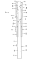
- FIG. FIG. 2 is a cross-sectional view of the terminal fitting of the first embodiment, showing a state in which the slide member is placed at a connection position relative to the connection member.
- FIG. 3 is a perspective view of the terminal fitting of the first embodiment, showing a state in which the sliding member is disposed at a spaced position relative to the connecting member.
- FIG. 4 is a perspective view of a connecting member in the terminal fitting of the first embodiment.
- FIG. 5 is a perspective view of the connecting member of the terminal fitting of the first embodiment, seen from a different direction than that of FIG. FIG.
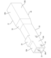
- FIG. 6 is a perspective view of a slide member in the terminal fitting of the first embodiment.
- FIG. 7 is a rear view of the slide member in the terminal fitting of the first embodiment.
- FIG. 8 is a plan view showing a state in which the terminal fitting of the first embodiment is accommodated in a housing and an electric wire is inserted into the terminal fitting.
- the terminal fitting of the present disclosure is (1) A terminal fitting connected to an exposed conductor exposed from the coating at the end of an electric wire, comprising: a connection member into which the exposed conductor is inserted and having a contact portion; and a slide member attached to the connection member so as to be slidable between a spaced position where the exposed conductor is spaced from the contact portion and a connection position where the exposed conductor is in contact with the contact portion, wherein the slide member has a covering portion that covers the exposed conductor within a stroke range as it slides from the spaced position to the connection position.
- the cover portion covers the exposed conductor within the stroke range in which the sliding member slides from the separated position to the connected position, preventing the exposed conductor from interfering with foreign objects and keeping the exposed conductor protected.
- the cover portion has a cylindrical shape capable of covering the entire circumference of the exposed conductor.
- the cylindrical covering portion can cover the entire circumference of the exposed conductor, which more reliably prevents the exposed conductor from interfering with foreign objects.
- connection member has a connection piece extending inward of the slide member, the contact portion is formed midway in the extension direction of the connection piece, the connection piece has a pressing portion at the tip side in the extension direction, and the slide member has a first pressing portion that presses the contact portion against the exposed conductor at the connection position and a second pressing portion that presses the pressing portion against the coating at the connection position.
- the first pressing portion presses the contact portion against the exposed conductor, electrically connecting the connection member to the electric wire
- the second pressing portion presses the retaining portion, mechanically connecting the connection member to the electric wire. This increases the holding force with which the connection member holds the electric wire.
- the terminal fitting 10 of the first embodiment includes a connecting member 11 and a sliding member 12 that are separate from each other.
- the connecting member 11 and the sliding member 12 are both formed by punching a conductive metal plate and then bending the same.
- the front-rear direction refers to the side where the connecting member 11 is located relative to the sliding member 12.
- the up-down direction refers to the up-down direction in each of the figures except for Figures 5 and 8.
- connection member 11 has a cylindrical, for example, rectangular, connection body 13 and a pair of connection pieces 14, 15 extending rearward from the connection body 13.
- the connection body 13 extends in the front-rear direction and is open on both the front and rear sides.
- the connection body 13 is configured such that the vertical dimension is larger than the horizontal dimension.
- the connection member 11 has a locking portion 16 protruding upward from the upper wall 13A of the connection body 13. The locking portion 16 is locked in a locking hole 91 (see Fig. 8) of the housing 90, and the terminal fitting 10 is accommodated in the housing 90.
- the housing 90 shown in Fig. 8 is illustrated without a cover member that covers the terminal fitting 10 from above.
- connection member 11 has a mating contact portion (not shown) inside the connection body 13.
- the mating contact portion is connected to a tab of a mating terminal fitting (not shown).
- the tab is inserted into the connection member 11 from the front of the connection member 11, contacts the mating contact portion, and is connected to the connection member 11.
- each of the connection pieces 14, 15 is in the form of a strip extending continuously rearward from the rear end of each of the upper wall 13A and the lower wall 13B of the connection body 13.
- Each of the connection pieces 14, 15 is elastically deformable in the direction of approaching and separating from each other (up-down direction, inward-outward direction) with the rear end of each of the upper wall 13A and the lower wall 13B of the connection body 13 as a fulcrum.
- Each of the connection pieces 14, 15 has a curved surface portion 21 between the middle of the front-rear direction and the rear end, and the curved surface portion 21 makes the vertical separation distance of the rear end larger than the vertical separation distance of the front end.
- connection pieces 14, 15 has contact portions 22 in the middle of the front-rear direction that face each other in the vertical direction. As shown in Figures 4 and 5, each of the contact portions 22 is formed on the inner surface of a thick portion formed in the middle of the front-rear direction of each of the connection pieces 14, 15.
- the thick portions of each of the connection pieces 14, 15 can be formed, for example, by stacking the plate materials that make up each of the connection pieces 14, 15.
- a recess may be formed on the inner surface of this thick portion, and as shown in FIG. 4, the contact portion 22 may include a recess.
- Each connection piece 14, 15 has a pressing portion 23 at its rear end that faces each other in the up-down direction. As shown in Figures 4 and 5, each pressing portion 23 is formed on the inner surface of a thick portion formed at the rear end of each connection piece 14, 15.
- the thick portion of each connection piece 14, 15 can be formed, for example, by stacking the plate materials that make up each connection piece 14, 15.
- a recess may be formed on the inner surface of this thick portion, and as shown in Figure 4, the pressing portion 23 may include a recess.
- connection member 11 has a pair of position control parts 24 on the side walls 13C on both the left and right sides of the connection body 13.
- Each position control part 24 is claw-shaped and is formed by cutting out part of the rear end of the side wall 13C outward.
- the slide member 12 has cylindrical, for example, rectangular cylindrical cover parts 25, 26 as a whole.
- the cover parts 25, 26 are configured so that the vertical dimension is larger than the horizontal dimension.
- the cover parts 25, 26 extend in the front-rear direction and are open on both the front and rear sides.
- the front-rear length of the cover parts 25, 26 is longer than the front-rear length of each of the connection pieces 14, 15.
- the electric wire 81 is, for example, a coated electric wire, and at the front end, the coating 82 is stripped off to expose the conductor 83 consisting of a core wire or the like.
- the conductor exposed at the front end of the electric wire 81 is referred to as the exposed conductor 83.
- the electric wires 81 are provided on a wiring member 80.
- the wiring member 80 is a flat member, and has an insulating sheet portion 84 made of nonwoven fabric or the like that fixes the multiple electric wires 81 in parallel. With such a wiring member 80, it is possible to insert the multiple electric wires 81 into the corresponding terminal fittings 10 all at once by moving the sheet portion 84.
- the cover parts 25, 26 have a first cover part 25 arranged on the front side and a second cover part 26 arranged on the rear side.
- the second cover part 26 is formed to be slightly larger than the first cover part 25.
- the first cover part 25 is formed into a rectangular tube shape by an upper wall 25A, a lower wall 25B, and left and right side walls 25C.
- the second cover part 26 is also formed into a rectangular tube shape by an upper wall 26A, a lower wall 26B, and left and right side walls 26C.
- the second cover portion 26 has a sloped tapered portion 28 at the front end of each of the upper wall 26A, the lower wall 26B, and the left and right side walls 26C, which tapers forward and connects to the upper wall 25A, the lower wall 25B, and the left and right side walls 25C of the first cover portion 25.
- the first cover portion 25 has an engagement portion 29 protruding from a position near the front end of the upper wall 25A.
- the engagement portion 29 is formed, for example, by cutting out a part of the upper wall 25A of the first cover portion 25.
- the engagement portion 29 is pressed by a jig (not shown) when the slide member 12 is slid.
- the cover parts 25, 26 have a pair of connection position receiving parts 31 and separation position receiving parts 32 on the left and right side walls 25C of the first cover part 25.
- Each separation position receiving part 32 is provided with a rectangular opening shape penetrating the front end side of the side wall 25C of the first cover part 25.
- Each connection position receiving part 31 is provided with a rectangular opening shape penetrating the side wall 25C of the first cover part 25 rearward of each separation position receiving part 32 at the midpoint between the front and rear of the side wall 25C of the first cover part 25.
- the slide member 12 is shallowly fitted into the connecting member 11, and each position regulating portion 24 of the connecting member 11 elastically fits into each separated position receiving portion 32, thereby holding the slide member 12 in a state where movement is restricted to the separated position relative to the connecting member 11.
- the slide member 12 is deeply fitted into the connecting member 11, and each position regulating portion 24 of the connecting member 11 elastically fits into each connected position receiving portion 31, thereby holding the slide member 12 in a state where movement is restricted to the connected position relative to the connecting member 11.
- the covering parts 25, 26 have a pair of mutually opposing first pressing parts 33 on each of the upper wall 25A and the lower wall 25B of the first covering part 25.
- the first pressing part 33 of the upper wall 25A can be formed by bending the lower upper wall 25A downward, and has a lower surface extending in the front-to-rear direction.
- the first pressing part 33 of the lower wall 25B can be formed by bending the lower wall 25B upward, and has an upper surface extending in the front-to-rear direction.
- the covering parts 25, 26 have a pair of mutually opposing second pressing parts 35 on each of the upper wall 26A and the lower wall 26B of the second covering part 26.
- the second pressing part 35 of the upper wall 26A can be formed by bending the lower upper wall 26A downward, and has a lower surface extending in the front-to-rear direction.
- the second pressing part 35 of the lower wall 26B can be formed by bending the lower wall 26B upward, and has an upper surface extending in the front-to-rear direction.
- the terminal fitting 10 is accommodated in the housing 90 in advance.
- the slide member 12 is held in the spaced position relative to the connection member 11 by the engagement between the position restricting portions 24 and the spaced position receiving portions 32 (see FIG. 3 ).
- the exposed conductor 83 of the electric wire 81 is inserted into the terminal fitting 10.
- the exposed conductor 83 is inserted into the second cover portion 26 from the rear of the second cover portion 26, and is disposed from the second cover portion 26 to the first cover portion 25.
- the connection pieces 14, 15 are disposed away from the exposed conductor 83.
- the exposed conductor 83 is covered and protected by the cover portions 25, 26 of the slide member 12 and the connection member 11.
- the first pressing portions 33 slide along the front and rear intermediate portions of the connection pieces 14, 15 while the curved surface portion 21 is deformed, and press the contact portions 22 of the connection pieces 14, 15 inward.
- the contact portions 22 of the connection pieces 14, 15 are pressed by the first pressing portions 33 to approach each other, and come into strong contact with the exposed conductor 83 to sandwich the exposed conductor 83 from above and below (see FIG. 2).
- the second pressing portions 35 slide along the rear end (tip) of the connection pieces 14, 15 to press the holding portions 23 of the connection pieces 14, 15 inward.
- connection pieces 14, 15 are pressed by the second pressing portions 35 to approach each other, and come into strong contact with the front end of the insulation 82 of the electric wire 81 to sandwich the insulation 82 from above and below. In this way, each connection piece 14, 15 clamps the exposed conductor 83 and coating 82 of the electric wire 81, so that the terminal fitting 10 is electrically and mechanically connected to the electric wire 81.
- the cover parts 25 and 26 cover the exposed conductor 83 within the stroke range in which the slide member 12 slides from the separated position to the connected position, so that the exposed conductor 83 can be prevented from interfering with foreign objects and the exposed conductor 83 can be kept protected.
- the covering portions 25 and 26 are cylindrical and can cover the entire circumference of the exposed conductor 83, it is possible to more reliably prevent the exposed conductor 83 from interfering with foreign objects.
- connection member 11 has a contact portion 22 midway in the extension direction of the connection pieces 14, 15, and a pressing portion 23 at the tip side (rear end side) of the extension direction of the connection pieces 14, 15.
- the slide member 12 has a first pressing portion 33 that presses the contact portion 22 against the exposed conductor 83 at the connection position, and a second pressing portion 35 that presses the pressing portion 23 against the coating 82 at the connection position. Therefore, when the slide member 12 reaches the connection position, the first pressing portion 33 presses the contact portion 22 against the exposed conductor 83, electrically connecting the connection member 11 to the electric wire 81, and the second pressing portion 35 presses the pressing portion 23, mechanically connecting the connection member 11 to the electric wire 81. This increases the holding force with which the connection member 11 holds the electric wire 81.
- the covering portion is formed to cover the entire circumference of the exposed conductor.
- the covering portion may have an opening shape that does not cover a part of the exposed conductor, as long as interference between the exposed conductor and a foreign object can be avoided.
- the contact portion and the pressing portion are formed on a common (same) connecting piece.
- the contact portion and the pressing portion may be formed on different connecting pieces.
- the electric wire is provided in a wiring member fixed to the sheet portion.
- the electric wire may be configured as a linear covered electric wire without being fixed to the sheet portion.
- the pressing portion is set to contact the coating at the same time as the contact portion is set to contact the exposed conductor.
- the pressing portion may be set to contact the coating after the contact portion is set to contact the exposed conductor.
- the pressing portion may be set to contact the coating after the contact portion is set to contact the exposed conductor.
- connection member 12 Slide member 13: Connection body 13A: Upper wall of connection body 13B: Lower wall of connection itself 13C: Side wall of connection body 14: Upper connection piece 15: Lower connection piece 16: Locking portion 21: Curved surface portion 22: Contact portion 23: Pressing portion 24: Position regulating portion 25: First cover portion (cover portion) 25A: Upper wall of the first cover portion 25B: Lower wall of the first cover portion 25C: Side wall of the first cover portion 26: Second cover portion (cover portion) 26A: Upper wall of second cover portion 26B: Lower wall of second cover portion 26C: Side wall of second cover portion 28: Reduced diameter portion 29: Engagement portion 31: Connection position receiving portion 32: Separation position receiving portion 33: First pressing portion 35: Second pressing portion 80: Wiring member 81: Electric wire 82: Covering 83: Exposed conductor (conductor) 84: Seat portion 90: Housing 91: Locking hole
Landscapes
- Connector Housings Or Holding Contact Members (AREA)
- Connections Effected By Soldering, Adhesion, Or Permanent Deformation (AREA)
Abstract
端子金具(10)は、電線(81)の被覆(82)から露出する露出導体(83)が挿入され、接触部(22)を有する接続部材(11)と、接続部材(11)に対し、露出導体(83)が接触部(22)から離れた離間位置と接触部(22)に接触する接続位置との間をスライド可能に装着されるスライド部材(12)と、を備える。スライド部材(12)は、離間位置から接続位置へとスライドするストローク範囲で、露出導体(83)を覆う覆い部(25,26)を有している。
Description
本開示は、端子金具に関する。
特許文献1は、端子本体と称される接続部材と、接続部材に装着されるスライド部材と、を備えた端子金具を開示している。端子金具は、ハウジングに収容される。接続部材には、電線の端末部における被覆から露出する露出導体(芯線)が挿入される。スライド部材は、接続部材に対し、露出導体が接続部材の接触部(接触面)から離れた離間位置と接触部に接触する接続位置との間をスライド可能とされている。
端子金具と電線との接続作業の一例を説明すると、まず端子金具がハウジングに収容され、ハウジングの後面に治具が当てられる。その状態で、電線の露出導体が治具に形成された誘い込み部によってガイドされつつスライド部材から接続部材へと挿入される。続いて、治具が離脱させられ、スライド部材が離間位置から接続位置へと押し込まれる。これにより、電線の露出導体が接続部材の接触部に接触可能な状態になる。
上記のように、誘い込み部が形成された治具を使用して、接続部材に露出導体を挿入する作業を行うと、治具の離脱後、ハウジングの後方に、露出導体の一部が露出したまま残ることになる。このため、露出導体の一部に異物が干渉して損傷等する懸念がある。
そこで、本開示は、被覆から露出する露出導体を保護することが可能な端子金具を提供することを目的とする。
本開示の端子金具は、電線の端末部で被覆から露出する露出導体に接続される端子金具であって、前記露出導体が挿入され、接触部を有する接続部材と、前記接続部材に対し、前記露出導体が前記接触部から離れた離間位置と前記接触部に接触する接続位置との間をスライド可能に装着されるスライド部材と、を備え、前記スライド部材は、前記離間位置から前記接続位置へとスライドするストローク範囲で、前記露出導体を覆う覆い部を有している。
本開示によれば、被覆から露出する露出導体を保護することが可能な端子金具を提供することができる。
[本開示の実施形態の説明]
最初に本開示の実施態様を列記して説明する。
本開示の端子金具は、
(1)電線の端末部で被覆から露出する露出導体に接続される端子金具であって、前記露出導体が挿入され、接触部を有する接続部材と、前記接続部材に対し、前記露出導体が前記接触部から離れた離間位置と前記接触部に接触する接続位置との間をスライド可能に装着されるスライド部材と、を備え、前記スライド部材は、前記離間位置から前記接続位置へとスライドするストローク範囲で、前記露出導体を覆う覆い部を有している。
最初に本開示の実施態様を列記して説明する。
本開示の端子金具は、
(1)電線の端末部で被覆から露出する露出導体に接続される端子金具であって、前記露出導体が挿入され、接触部を有する接続部材と、前記接続部材に対し、前記露出導体が前記接触部から離れた離間位置と前記接触部に接触する接続位置との間をスライド可能に装着されるスライド部材と、を備え、前記スライド部材は、前記離間位置から前記接続位置へとスライドするストローク範囲で、前記露出導体を覆う覆い部を有している。
スライド部材が離間位置から接続位置へとスライドするストローク範囲で、覆い部が露出導体を覆うから、露出導体が異物と干渉することを回避でき、露出導体を保護状態に置くことができる。
(2)上記(1)に記載の端子金具において、前記覆い部は、前記露出導体の全周を覆うことが可能な筒形状をなしていることが好ましい。
筒形状の覆い部が露出導体の全周を覆うことが可能とされるため、露出導体が異物と干渉することをより確実に回避できる。
(3)上記(1)または(2)に記載の端子金具において、前記接続部材は、前記スライド部材の内側に延びる接続片を有し、前記接触部は、前記接続片の延び方向の途中に形成され、前記接続片は、前記延び方向の先端側に、押さえ部を有し、前記スライド部材は、前記接続位置で前記接触部を前記露出導体に押圧する第1押圧部と、前記接続位置で前記押さえ部を前記被覆に押圧する第2押圧部と、を有していることが好ましい。
スライド部材が接続位置に至ると、第1押圧部が接触部を露出導体に押圧して、接続部材が電線に電気的に接続されるのに加え、第2押圧部が押さえ部を押圧して、接続部材が電線に機械的に接続される。よって、接続部材が電線を保持する保持力を高めることができる。
[本開示の実施形態の詳細]
本開示の具体例を、以下に図面を参照しつつ説明する。なお、本発明はこの例示に限定されるものではなく、請求の範囲によって示され、請求の範囲と均等の意味および範囲内でのすべての変更が含まれることが意図される。
本開示の具体例を、以下に図面を参照しつつ説明する。なお、本発明はこの例示に限定されるものではなく、請求の範囲によって示され、請求の範囲と均等の意味および範囲内でのすべての変更が含まれることが意図される。
<実施形態1>
実施形態1の端子金具10は、図1-図3に示すように、互いに別体の接続部材11およびスライド部材12を備えている。接続部材11およびスライド部材12は、いずれも導電性の金属板を打ち抜いた後、曲げ加工等して形成される。なお、以下の説明において、前後方向については、スライド部材12に対して接続部材11が位置する側を前側とする。上下方向は、図5および図8を除く各図の上下方向を基準とする。
実施形態1の端子金具10は、図1-図3に示すように、互いに別体の接続部材11およびスライド部材12を備えている。接続部材11およびスライド部材12は、いずれも導電性の金属板を打ち抜いた後、曲げ加工等して形成される。なお、以下の説明において、前後方向については、スライド部材12に対して接続部材11が位置する側を前側とする。上下方向は、図5および図8を除く各図の上下方向を基準とする。
(接続部材)
接続部材11は、図4および図5に示すように、筒状、例えば、角筒状の接続本体13と、接続本体13から後方に延びる一対の接続片14,15と、を有している。接続本体13は、前後方向に延び、前後両側に開放されている。本実施形態1の場合、接続本体13は、左右寸法よりも上下寸法を大きくして構成される。接続部材11は、接続本体13の上壁13Aから上方に突出する係止部16を有している。係止部16は、ハウジング90の係止孔91(図8を参照)に係止され、端子金具10をハウジング90に収容させる。なお、図8に示すハウジング90は、端子金具10を上方から覆うカバー部材を省略して図示している。
接続部材11は、図4および図5に示すように、筒状、例えば、角筒状の接続本体13と、接続本体13から後方に延びる一対の接続片14,15と、を有している。接続本体13は、前後方向に延び、前後両側に開放されている。本実施形態1の場合、接続本体13は、左右寸法よりも上下寸法を大きくして構成される。接続部材11は、接続本体13の上壁13Aから上方に突出する係止部16を有している。係止部16は、ハウジング90の係止孔91(図8を参照)に係止され、端子金具10をハウジング90に収容させる。なお、図8に示すハウジング90は、端子金具10を上方から覆うカバー部材を省略して図示している。
接続部材11は、接続本体13の内部に、図示しない相手接触部を有している。相手接触部は、図示しない相手端子金具のタブに接続される。タブは、接続部材11の前方から接続部材11の内部に挿入され、相手接触部に接触して接続部材11に接続される。
各接続片14,15は、図4および図5に示すように、接続本体13の上壁13Aおよび下壁13Bの各々の後端から後方に連続して延びる帯板状をなしている。各接続片14,15は、接続本体13の上壁13Aおよび下壁13Bの各々の後端を支点として互いに接近、離間する方向(上下方向、内外方向)に弾性変形可能とされている。各接続片14,15は、前後方向の途中と後端部との間に曲面部21を有し、曲面部21を介して後端部の上下方向の離間距離を前端部の上下方向の離間距離よりも大きくしている。各接続片14,15は、前後方向の途中に、上下方向で互いに対向する接触部22を有している。図4および図5に示すように、各接触部22は、各接続片14,15の前後方向の途中に形成された厚肉部分の内面に形成されている。各接続片14,15の厚肉部分は、例えば、各接続片14,15を構成する板材を積層することによって形成可能である。この厚肉部分の内面には凹みが形成されていても良く、図4に示すように、接触部22が凹みを含んでいても良い。
各接続片14,15は、後端部に、上下方向で互いに対向する押さえ部23を有している。図4および図5に示すように、各押さえ部23は、各接続片14,15の後端部に形成された厚肉部分の内面に形成されている。各接続片14,15の厚肉部分は、例えば、各接続片14,15を構成する板材を積層することによって形成可能である。この厚肉部分の内面には凹みが形成されていても良く、図4に示すように、押さえ部23が凹みを含んでいても良い。
接続部材11は、図4および図5に示すように、接続本体13の左右両側の側壁13Cに、一対の位置規制部24を有している。各位置規制部24は、爪状をなし、側壁13Cの後端側の一部を外側に切り起こして形成される。
(スライド部材)
スライド部材12は、図6に示すように、全体として、筒状、例えば、角筒状の覆い部25,26を有している。本実施形態1の場合、覆い部25,26は、左右寸法よりも上下寸法を大きくして構成される。覆い部25,26は、前後方向に延び、前後両側に開放されている。図2に示すように、覆い部25,26の前後方向の長さは、各接続片14,15の前後方向の長さよりも長い。スライド部材12は、接続部材11の各接続片14,15を挿入した状態で、接続部材11に対し、離間位置(図3を参照)と接続位置(図1および図2を参照)との間をスライド可能(摺動可能)とされている。スライド部材12が接続位置にあるときに、接続部材11が電線81に電気的および機械的に接続される。
スライド部材12は、図6に示すように、全体として、筒状、例えば、角筒状の覆い部25,26を有している。本実施形態1の場合、覆い部25,26は、左右寸法よりも上下寸法を大きくして構成される。覆い部25,26は、前後方向に延び、前後両側に開放されている。図2に示すように、覆い部25,26の前後方向の長さは、各接続片14,15の前後方向の長さよりも長い。スライド部材12は、接続部材11の各接続片14,15を挿入した状態で、接続部材11に対し、離間位置(図3を参照)と接続位置(図1および図2を参照)との間をスライド可能(摺動可能)とされている。スライド部材12が接続位置にあるときに、接続部材11が電線81に電気的および機械的に接続される。
図2に示すように、電線81は、例えば、被覆電線であって、前端部において、被覆82が皮剥ぎされ、芯線等からなる導体83が露出している。以下、電線81の前端部において露出する導体を、露出導体83と称する。
本実施形態1の場合、図8に示すように、電線81は、配線部材80に設けられている。配線部材80は、扁平な部材であって、複数本の電線81を並列に固定する不織布等からなる絶縁性のシート部84を有している。このような配線部材80であれば、シート部84を移動させることで、複数本の電線81をそれぞれに対応する端子金具10に一括して挿入することが可能となる。
覆い部25,26は、図6に示すように、前側に配置される第1覆い部25と、後側に配置される第2覆い部26と、を有している。第2覆い部26は、第1覆い部25よりも一回り大きく形成されている。第1覆い部25は、上壁25A、下壁25Bおよび左右の側壁25Cによって四角筒状に形成されている。第2覆い部26も、上壁26A、下壁26Bおよび左右の側壁26Cによって四角筒状に形成されている。
第2覆い部26は、上壁26A、下壁26Bおよび左右の側壁26Cの各々の前端部に、前方に向けて縮径し、それぞれ、第1覆い部25の上壁25A、下壁25Bおよび左右の側壁25Cに連なる斜面状の縮径部28を有している。
第1覆い部25は、上壁25Aの前端部寄りの位置に、係合部29を突設させている。係合部29は、例えば、第1覆い部25の上壁25Aの一部を切り起こして形成される。係合部29は、スライド部材12をスライドする際に、図示しない治具によって押圧される。
覆い部25,26は、第1覆い部25の左右両側の側壁25Cに、前後一対ずつの接続位置受け部31および離間位置受け部32を有している。各離間位置受け部32は、第1覆い部25の側壁25Cの前端側に、矩形の開口形状で貫設されている。各接続位置受け部31は、第1覆い部25の側壁25Cの前後中間側における各離間位置受け部32よりも後方に、各離間位置受け部32と同様、矩形の開口形状で貫設されている。
図3に示すように、スライド部材12が接続部材11に浅く嵌合され、接続部材11の各位置規制部24が各離間位置受け部32に弾性的に嵌り込むことにより、スライド部材12が接続部材11に対して離間位置に移動を規制された状態に保持される。図1に示すように、スライド部材12が接続部材11に深く嵌合され、接続部材11の各位置規制部24が各接続位置受け部31に弾性的に嵌り込むことにより、スライド部材12が接続部材11に対して接続位置に移動を規制された状態に保持される。
覆い部25,26は、図2および図7に示すように、第1覆い部25の上壁25Aおよび下壁25Bの各々に、互いに対向する一対の第1押圧部33を有している。上壁25Aの第1押圧部33は、下側の上壁25Aを下向きに屈曲させることで形成可能であり、前後方向に延びる下面を有している。下壁25Bの第1押圧部33は、下壁25Bを上向きに屈曲させることで形成可能であり、前後方向に延びる上面を有している。
覆い部25,26は、図2および図7に示すように、第2覆い部26の上壁26Aおよび下壁26Bの各々に、互いに対向する一対の第2押圧部35を有している。上壁26Aの第2押圧部35は、下側の上壁26Aを下向きに屈曲させることで形成可能であり、前後方向に延びる下面を有している。下壁26Bの第2押圧部35は、下壁26Bを上向きに屈曲させることで形成可能であり、前後方向に延びる上面を有している。
(端子金具の作用)
端子金具10は、予めハウジング90に収容される。このとき、スライド部材12は、各位置規制部24と各離間位置受け部32との係止によって、接続部材11に対して離間位置に保持される(図3を参照)。その状態で、端子金具10に電線81の露出導体83が挿入される。露出導体83は、第2覆い部26の後方から第2覆い部26に挿入され、第2覆い部26から第1覆い部25にわたって配置される。スライド部材12が離間位置にあるときに、各接続片14,15は露出導体83から離れて配置される。露出導体83は、スライド部材12の覆い部25,26および接続部材11によって覆われて保護される。
端子金具10は、予めハウジング90に収容される。このとき、スライド部材12は、各位置規制部24と各離間位置受け部32との係止によって、接続部材11に対して離間位置に保持される(図3を参照)。その状態で、端子金具10に電線81の露出導体83が挿入される。露出導体83は、第2覆い部26の後方から第2覆い部26に挿入され、第2覆い部26から第1覆い部25にわたって配置される。スライド部材12が離間位置にあるときに、各接続片14,15は露出導体83から離れて配置される。露出導体83は、スライド部材12の覆い部25,26および接続部材11によって覆われて保護される。
その状態で、図示しない治具が係合部29に当てがわれ、係合部29が治具によって前方に押圧される。これにより、各位置規制部24と各離間位置受け部32との係止が解除され、スライド部材12が接続部材11に対して前進して接続位置に移動させられる。
スライド部材12が接続位置に至る際に、曲面部21の変形を伴いつつ各第1押圧部33が各接続片14,15の前後途中部位を摺動して各接続片14,15の接触部22を内側に押圧する。各接続片14,15の接触部22は、各第1押圧部33により押圧されて互いに接近し、露出導体83と強く接触して露出導体83を上下方向から挟み込む(図2を参照)。また、スライド部材12が接続位置に至る際に、各第2押圧部35が各接続片14,15の後端部(先端部)を摺動して各接続片14,15の押さえ部23を内側に押圧する。各接続片14,15の押さえ部23は、各第2押圧部35により押圧されて互いに接近し、電線81の被覆82の前端部と強く接触して被覆82を上下方向から挟み込む。こうして各接続片14,15が電線81の露出導体83および被覆82を挟み込むことにより、端子金具10が電線81に電気的および機械的に接続される。
スライド部材12が離間位置から接続位置に移動する間、およびスライド部材12が接続位置にあるときに、露出導体83は、スライド部材12の覆い部25,26によって覆われて保護される状態が維持される。
以上説明したように、本実施形態1によれば、スライド部材12が離間位置から接続位置へとスライドするストローク範囲で、覆い部25,26が露出導体83を覆うため、露出導体83が異物と干渉することを回避でき、露出導体83を保護状態に置くことができる。
また、覆い部25,26が露出導体83の全周を覆うことが可能な筒形状をなしているため、露出導体83が異物と干渉することをより確実に回避できる。
また、接続部材11は、接続片14,15の延び方向の途中に接触部22を有し、接続片14,15の延び方向の先端側(後端側)に押さえ部23を有している。スライド部材12は、接続位置で接触部22を露出導体83に押圧する第1押圧部33と、接続位置で押さえ部23を被覆82に押圧する第2押圧部35と、を有している。このため、スライド部材12が接続位置に至ると、第1押圧部33が接触部22を露出導体83に押圧して、接続部材11が電線81に電気的に接続されるのに加え、第2押圧部35が押さえ部23を押圧して、接続部材11が電線81に機械的に接続される。よって、接続部材11が電線81を保持する保持力を高めることができる。
[本開示の他の実施形態]
今回開示された上記実施形態1はすべての点で例示であって制限的なものではないと考えるべきである。
上記実施形態1の場合、覆い部は、露出導体の全周を覆うように形成されていた。これに対し、他の実施形態によれば、覆い部は、露出導体と異物との干渉を回避可能である限り、露出導体の一部を覆わない開口形状を有していても良い。
上記実施形態1の場合、接触部および押さえ部は、互いに共通(同一)の接続片に形成されていた。これに対し、他の実施形態によれば、接触部および押さえ部は、互いに異なる別の接続片に形成されていても良い。
上記実施形態1の場合、電線は、シート部に固定された配線部材に設けられていた。これに対し、他の実施形態の場合、電線は、シート部に固定されず、全体が線状の被覆電線として構成されていても良い。
上記実施形態1の場合、接触部が露出導体に接触するのと同時に、押さえ部が被覆と接触するように設定されていた。これに対し、他の実施形態の場合、接触部が露出導体に接触した後、押さえ部が被覆と接触するように設定されていても良い。あるいは、押さえ部が被覆と接触した後、接触部が露出導体に接触するように設定されていても良い。
今回開示された上記実施形態1はすべての点で例示であって制限的なものではないと考えるべきである。
上記実施形態1の場合、覆い部は、露出導体の全周を覆うように形成されていた。これに対し、他の実施形態によれば、覆い部は、露出導体と異物との干渉を回避可能である限り、露出導体の一部を覆わない開口形状を有していても良い。
上記実施形態1の場合、接触部および押さえ部は、互いに共通(同一)の接続片に形成されていた。これに対し、他の実施形態によれば、接触部および押さえ部は、互いに異なる別の接続片に形成されていても良い。
上記実施形態1の場合、電線は、シート部に固定された配線部材に設けられていた。これに対し、他の実施形態の場合、電線は、シート部に固定されず、全体が線状の被覆電線として構成されていても良い。
上記実施形態1の場合、接触部が露出導体に接触するのと同時に、押さえ部が被覆と接触するように設定されていた。これに対し、他の実施形態の場合、接触部が露出導体に接触した後、押さえ部が被覆と接触するように設定されていても良い。あるいは、押さえ部が被覆と接触した後、接触部が露出導体に接触するように設定されていても良い。
10…端子金具
11…接続部材
12…スライド部材
13…接続本体
13A…接続本体の上壁
13B…接続本来の下壁
13C…接続本体の側壁
14…上側の接続片
15…下側の接続片
16…係止部
21…曲面部
22…接触部
23…押さえ部
24…位置規制部
25…第1覆い部(覆い部)
25A…第1覆い部の上壁
25B…第1覆い部の下壁
25C…第1覆い部の側壁
26…第2覆い部(覆い部)
26A…第2覆い部の上壁
26B…第2覆い部の下壁
26C…第2覆い部の側壁
28…縮径部
29…係合部
31…接続位置受け部
32…離間位置受け部
33…第1押圧部
35…第2押圧部
80…配線部材
81…電線
82…被覆
83…露出導体(導体)
84…シート部
90…ハウジング
91…係止孔
11…接続部材
12…スライド部材
13…接続本体
13A…接続本体の上壁
13B…接続本来の下壁
13C…接続本体の側壁
14…上側の接続片
15…下側の接続片
16…係止部
21…曲面部
22…接触部
23…押さえ部
24…位置規制部
25…第1覆い部(覆い部)
25A…第1覆い部の上壁
25B…第1覆い部の下壁
25C…第1覆い部の側壁
26…第2覆い部(覆い部)
26A…第2覆い部の上壁
26B…第2覆い部の下壁
26C…第2覆い部の側壁
28…縮径部
29…係合部
31…接続位置受け部
32…離間位置受け部
33…第1押圧部
35…第2押圧部
80…配線部材
81…電線
82…被覆
83…露出導体(導体)
84…シート部
90…ハウジング
91…係止孔
Claims (3)
- 電線の端末部で被覆から露出する露出導体に接続される端子金具であって、
前記露出導体が挿入され、接触部を有する接続部材と、
前記接続部材に対し、前記露出導体が前記接触部から離れた離間位置と前記接触部に接触する接続位置との間をスライド可能に装着されるスライド部材と、を備え、
前記スライド部材は、前記離間位置から前記接続位置へとスライドするストローク範囲で、前記露出導体を覆う覆い部を有している、端子金具。 - 前記覆い部は、前記露出導体の全周を覆うことが可能な筒形状をなしている、請求項1に記載の端子金具。
- 前記接続部材は、前記スライド部材の内側に延びる接続片を有し、
前記接触部は、前記接続片の延び方向の途中に形成され、
前記接続片は、前記延び方向の先端側に、押さえ部を有し、
前記スライド部材は、前記接続位置で前記接触部を前記露出導体に押圧する第1押圧部と、前記接続位置で前記押さえ部を前記被覆に押圧する第2押圧部と、を有している、請求項1または請求項2に記載の端子金具。
Applications Claiming Priority (2)
| Application Number | Priority Date | Filing Date | Title |
|---|---|---|---|
| JP2023095351A JP2024176634A (ja) | 2023-06-09 | 2023-06-09 | 端子金具 |
| JP2023-095351 | 2023-06-09 |
Publications (1)
| Publication Number | Publication Date |
|---|---|
| WO2024252959A1 true WO2024252959A1 (ja) | 2024-12-12 |
Family
ID=93795487
Family Applications (1)
| Application Number | Title | Priority Date | Filing Date |
|---|---|---|---|
| PCT/JP2024/019257 Ceased WO2024252959A1 (ja) | 2023-06-09 | 2024-05-24 | 端子金具 |
Country Status (2)
| Country | Link |
|---|---|
| JP (1) | JP2024176634A (ja) |
| WO (1) | WO2024252959A1 (ja) |
Citations (5)
| Publication number | Priority date | Publication date | Assignee | Title |
|---|---|---|---|---|
| JP2000138078A (ja) * | 1998-10-30 | 2000-05-16 | Yazaki Corp | 高圧電線用接続端子 |
| JP2019061742A (ja) * | 2017-09-22 | 2019-04-18 | 古河電気工業株式会社 | コネクタ、コネクタの組立方法、コネクタ付ワイヤーハーネス、接続端子、及び、ハウジング |
| JP2020087671A (ja) * | 2018-11-22 | 2020-06-04 | 矢崎総業株式会社 | 端子接続構造 |
| JP2020202092A (ja) * | 2019-06-11 | 2020-12-17 | 株式会社オートネットワーク技術研究所 | 端子、及び、端子付き電線 |
| CN217607034U (zh) * | 2022-06-30 | 2022-10-18 | 珠海舍创科技有限公司 | 一种快速接线端子 |
-
2023
- 2023-06-09 JP JP2023095351A patent/JP2024176634A/ja active Pending
-
2024
- 2024-05-24 WO PCT/JP2024/019257 patent/WO2024252959A1/ja not_active Ceased
Patent Citations (5)
| Publication number | Priority date | Publication date | Assignee | Title |
|---|---|---|---|---|
| JP2000138078A (ja) * | 1998-10-30 | 2000-05-16 | Yazaki Corp | 高圧電線用接続端子 |
| JP2019061742A (ja) * | 2017-09-22 | 2019-04-18 | 古河電気工業株式会社 | コネクタ、コネクタの組立方法、コネクタ付ワイヤーハーネス、接続端子、及び、ハウジング |
| JP2020087671A (ja) * | 2018-11-22 | 2020-06-04 | 矢崎総業株式会社 | 端子接続構造 |
| JP2020202092A (ja) * | 2019-06-11 | 2020-12-17 | 株式会社オートネットワーク技術研究所 | 端子、及び、端子付き電線 |
| CN217607034U (zh) * | 2022-06-30 | 2022-10-18 | 珠海舍创科技有限公司 | 一种快速接线端子 |
Also Published As
| Publication number | Publication date |
|---|---|
| JP2024176634A (ja) | 2024-12-19 |
Similar Documents
| Publication | Publication Date | Title |
|---|---|---|
| CN111293452B (zh) | 软扁平电缆电连接器 | |
| JP6708025B2 (ja) | シールドコネクタ | |
| EP1986284B1 (en) | A connector and an assembling method therefor | |
| US7980880B2 (en) | Connector | |
| US20070275589A1 (en) | Connector | |
| EP2375512B1 (en) | Terminal fitting and production method therefor | |
| JP2000058204A (ja) | シールドコネクタ | |
| JP3601772B2 (ja) | コネクタ | |
| US20240275082A1 (en) | Electric cable connection system | |
| JP6782736B2 (ja) | 端子金具 | |
| WO2020203391A1 (ja) | 端子および端子付き電線 | |
| JP7121913B2 (ja) | 端子、および端子付き電線 | |
| JP6393418B2 (ja) | コネクタ | |
| EP3989369B1 (en) | Connection terminal | |
| JP3282717B2 (ja) | 圧接コネクタ | |
| JP2024176634A (ja) | 端子金具 | |
| JP7144290B2 (ja) | 端子接続構造 | |
| JP2012064536A (ja) | コネクタ組立体 | |
| JP5214503B2 (ja) | 差込形電線コネクタ | |
| EP2112715A2 (en) | Lock structure and cover lock structure of terminal cap | |
| US20230261423A1 (en) | Shield connector | |
| JP2005056600A (ja) | 電線端子 | |
| JP3601773B2 (ja) | 端子 | |
| US11894634B2 (en) | Connector | |
| JP7786299B2 (ja) | コネクタ及びコネクタの製造方法 |
Legal Events
| Date | Code | Title | Description |
|---|---|---|---|
| 121 | Ep: the epo has been informed by wipo that ep was designated in this application |
Ref document number: 24819191 Country of ref document: EP Kind code of ref document: A1 |
|
| NENP | Non-entry into the national phase |
Ref country code: DE |