WO2024252931A1 - 光ファイバ保持部品、光ファイバアセンブリ、光コネクタ、および光結合デバイス - Google Patents
光ファイバ保持部品、光ファイバアセンブリ、光コネクタ、および光結合デバイス Download PDFInfo
- Publication number
- WO2024252931A1 WO2024252931A1 PCT/JP2024/018860 JP2024018860W WO2024252931A1 WO 2024252931 A1 WO2024252931 A1 WO 2024252931A1 JP 2024018860 W JP2024018860 W JP 2024018860W WO 2024252931 A1 WO2024252931 A1 WO 2024252931A1
- Authority
- WO
- WIPO (PCT)
- Prior art keywords
- optical fiber
- ferrule
- flat surface
- optical
- face
- Prior art date
- Legal status (The legal status is an assumption and is not a legal conclusion. Google has not performed a legal analysis and makes no representation as to the accuracy of the status listed.)
- Ceased
Links
Images


Classifications
-
- G—PHYSICS
- G02—OPTICS
- G02B—OPTICAL ELEMENTS, SYSTEMS OR APPARATUS
- G02B6/00—Light guides; Structural details of arrangements comprising light guides and other optical elements, e.g. couplings
- G02B6/24—Coupling light guides
- G02B6/36—Mechanical coupling means
- G02B6/38—Mechanical coupling means having fibre to fibre mating means
-
- G—PHYSICS
- G02—OPTICS
- G02B—OPTICAL ELEMENTS, SYSTEMS OR APPARATUS
- G02B6/00—Light guides; Structural details of arrangements comprising light guides and other optical elements, e.g. couplings
- G02B6/24—Coupling light guides
- G02B6/36—Mechanical coupling means
- G02B6/40—Mechanical coupling means having fibre bundle mating means
Definitions
- the present disclosure relates to an optical fiber holding component, an optical fiber assembly, an optical connector, and an optical coupling device.
- Patent Document 1 discloses an MT connector for optically connecting multiple optical fibers to multiple other optical fibers at once.
- the MT connector in Patent Document 1 also uses multiple multi-core optical fibers (hereinafter referred to as "MCF"), each containing multiple cores, as the optical fibers. Therefore, the multiple MCFs, which are each aligned by rotating around the fiber axis, are temporarily held by multiple fiber holding parts that maintain the aligned state for one or two fibers at a time. By inserting these multiple optical fiber holding parts into ferrules, an MT connector in which the aligned state of the multiple MCFs is maintained is obtained.
- MCF multi-core optical fibers
- the optical fiber holding component of the present disclosure holds a plurality of optical fibers relative to a ferrule, and is fixed in a state where at least a portion of the optical fibers is inserted into the storage space of the ferrule.
- the ferrule has a front end face provided with a plurality of fiber holes into which the tip portions of the optical fibers are respectively inserted, a rear end face provided with an opening defined by an opening end with a plurality of recessed corners each chamfered, and a storage space extending from the rear end face toward the front end face and having the same cross-sectional shape as the opening.
- the optical fiber holding component also has a first end face and a second end face, a plurality of through holes, a first flat surface, and a pair of projected corners.
- the first end face and the second end face are arranged along a first direction from the front end face toward the rear end face of the ferrule.
- the plurality of through holes have a shape extending from the first end face along the first direction, are arranged along a second direction perpendicular to the first direction, and pass corresponding optical fibers among the plurality of optical fibers from the second end face toward the first end face.
- the first flat surface directly faces the ferrule flat surface.
- the ferrule flat surface is a reference installation surface that is a part of the inner wall surface that defines the storage space of the ferrule, and is a flat surface sandwiched between a pair of adjacent corners among the multiple corners. The pair of corners are arranged to sandwich the first flat surface along the second direction.
- each of the pair of corners is chamfered so that a non-contact state is maintained with respect to the pair of corners when the ferrule flat surface and the first flat surface are in contact.
- the width of the optical fiber holding component along the second direction satisfies the relationship that the width of the first flat surface is set to be equal to or less than the width of the ferrule flat surface, and the maximum width of the optical fiber holding component is longer than the width of the ferrule flat surface.
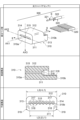
- FIG. 1 is a diagram showing an example of an assembly process for an optical coupling device according to the present disclosure.
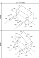
- FIG. 2 is a diagram showing an example of a ferrule structure that can be applied to the optical connector of the present disclosure.
- FIG. 3 is a diagram showing an example of the structure of the optical fiber assembly and holding equipment for optical fiber of the present disclosure.
- FIG. 4 is a diagram for explaining an inserted state of holding equipment for optical fiber of the present disclosure.
- FIG. 5 is a diagram for explaining the change in shape of the optical fiber after the optical fiber assembly is inserted into the ferrule.
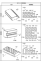
- FIG. 6 is a diagram showing a structure of a modified example of holding equipment for optical fiber of the present disclosure.
- the MT connector of Patent Document 1 had the problem of a complicated positioning mechanism for the ferrules and optical fiber holding parts. This is because, due to the structural nature of the MCF, all optical fiber holding parts must be individually positioned with high precision not only in the horizontal and vertical directions, but also in the rotational direction.
- each optical fiber holding component when multiple optical fiber holding components are adhesively fixed to a ferrule, a clearance for injecting adhesive is required between the ferrule and the multiple optical fiber holding components.
- the clearance can cause the multiple optical fiber holding components to become unstable when fixed in the ferrule.
- each optical fiber holding component will become misaligned with respect to the fiber hole of the ferrule that holds the tip portion of the MCF. In such a situation, even if multiple MCFs are inserted into the fiber hole of the ferrule, unnecessary stress will be applied to the part of the held MCF that is exposed from each optical fiber holding component, which may cause damage to the MCF.
- the present disclosure has been made to solve the problems described above, and aims to provide an optical fiber holding component, an optical fiber assembly, an optical connector, and an optical coupling device that are easy to fix to a ferrule and have a structure for limiting positional fluctuations before being fixed to the ferrule.
- the optical fiber holding component of the present disclosure is a component that holds multiple optical fibers relative to a ferrule and is fixed in a state where at least a portion of the optical fibers is inserted into the storage space of the ferrule.
- the optical fiber holding component also functions as a component that maintains the alignment state of each MCF.
- the ferrule in which at least a portion of the optical fiber holding component is inserted into the storage space, has a front end face with multiple fiber holes into which the tip portions of multiple optical fibers are respectively inserted, a rear end face with an opening defined by multiple chamfered opening ends at each of the multiple corners, and a storage space that extends from the rear end face toward the front end face and has the same cross-sectional shape as the opening.
- the optical fiber holding component is a component that is fixed to the ferrule while holding multiple optical fibers, and a part of it is inserted into the storage space from the opening.
- the optical fiber holding component has a first end face and a second end face, multiple through holes, a first flat surface, and a pair of corners.
- the first end face and the second end face are arranged along a first direction from the front end face to the rear end face of the ferrule.
- the multiple through holes have a shape extending from the first end face along the first direction, are arranged along a second direction perpendicular to the first direction, and each of the multiple optical fibers passes through a corresponding optical fiber from the second end face to the first end face.
- the first flat surface is an installation reference surface that is a part of the inner wall surface that defines the storage space of the ferrule, and directly faces the ferrule flat surface that is sandwiched between a pair of adjacent corners among the multiple corners.
- the pair of corners are arranged to sandwich the first flat surface along the second direction.
- each of the pair of corners is chamfered so that a non-contact state with the pair of corners is maintained when the ferrule flat surface and the first flat surface are in contact.
- the width of the optical fiber holding component along the second direction satisfies the relationship that the width of the first flat surface is set to be equal to or smaller than the width of the ferrule flat surface relative to the width of the ferrule along the second direction, and the maximum width of the optical fiber holding component is longer than the width of the ferrule flat surface.
- the "flat surface” disclosed in this specification means a surface having a curvature of 0.1 (1/mm) or less.
- a “corner” and a “corner” mean a portion sandwiched between a pair of adjacent “flat surfaces,” which are adjacent to the "corner” or “corner” and are continuous with each other.
- the "chamfering" of the corner of the opening end at the rear end face of the ferrule and the “chamfering" of the corner of the optical fiber holding component include “C-chamfering,” which processes the edge portion into a surface inclined at 45 degrees from the flat surface, and “R-chamfering,” which processes the surface of the edge portion smoothly.
- the rear end face of the ferrule, to which the optical fiber holding component is inserted and fixed has an opening defined by an opening end with multiple chamfered corners. Meanwhile, the corners of the optical fiber holding component are also chamfered so as not to come into contact with the corners.
- the width of the first flat surface of the optical fiber holding component is set to be equal to or smaller than the width of the ferrule flat surface, which serves as the installation reference surface. Meanwhile, the maximum width of the optical fiber holding component is set to be longer than the width of the ferrule flat surface.
- the width of the first flat surface between the pair of corners may be equal to the width of the ferrule flat surface.
- the corners of the opening end at the rear end face of the ferrule are chamfered, and the corners of the optical fiber holding component are also chamfered. Therefore, when the width of the first flat surface and the width of the ferrule flat surface are equal, the movement of the optical fiber holding component along the second direction is automatically restricted. In other words, once the first flat surface and the ferrule flat surface come into contact, the posture of the optical fiber holding component before fixing within the ferrule is stable.
- the multiple through holes arranged on the first end face may include multiple row forming groups each defined by one or more through holes arranged along the second direction, and the multiple row forming groups are arranged along a third direction perpendicular to both the first and second directions.
- the multiple through holes are arranged two-dimensionally on the first end face, making it possible for the optical fiber holding component to hold a larger number of optical fibers.
- multiple optical fibers are arranged not only in the second direction but also in the third direction, it becomes possible to significantly increase the number of optical fibers held by the optical fiber holding component, and as a result, the workability of mounting ferrules on multiple optical fibers is significantly improved.
- the first flat surface may be a surface parallel to both the first direction and the second direction.
- the first flat surface may also be a surface parallel to both the first direction and the third direction.
- the third direction is a direction perpendicular to each of the first direction and the second direction.
- the first flat surface is a surface parallel to both the first direction and the third direction
- the second direction which is the arrangement direction of the fiber holes of the ferrule
- the optical fiber holding component may have a second flat surface parallel to the first flat surface.
- the optical fiber holding component may have a third flat surface formed continuously from one of the pair of corners to the first flat surface.
- the first flat surface and the third flat surface may be perpendicular to each other.
- the first end face may have a rectangular shape.
- both the first end face and the second end face are located within the storage space.
- only the first end face is located within the storage space. In either case, the optical fiber holding component becomes easier to handle, and the optical fiber holding component can be positioned with high precision within the ferrule.
- the optical fiber assembly of the present disclosure includes an optical fiber holding component having a structure described in any one of (1) to (7) above, and a plurality of optical fibers.
- the plurality of optical fibers are fixed in each of a plurality of through holes of the optical fiber holding component.
- the tip portion of each of the plurality of optical fibers inserted into a plurality of fiber holes arranged on the front end face of the ferrule has the resin coating covering the glass portion removed. Therefore, the portion of the optical fiber held in each of the plurality of through holes of the optical fiber holding component may be the portion from which the resin coating has been removed, or may be the portion covered with the resin coating. In this way, when the optical fiber holding component of the present disclosure disclosed in any one of (1) to (7) above is applied, an optical fiber assembly that is easy to handle is obtained.
- the optical connector of the present disclosure comprises the optical fiber assembly described in (8) above and a ferrule. As described above, at least a portion of the optical fiber assembly is inserted into the storage space of the ferrule. In such a configuration, the position of the optical fiber holding component in the storage space of the ferrule is maintained with a portion of the optical fiber holding component in contact with the flat surface of the ferrule. The tip portions of the multiple optical fibers are inserted into the multiple fiber holes of the ferrule while being fixed in the multiple through holes of the optical fiber holding component. In this case, an optical connector is obtained in which high rotation alignment accuracy is maintained for each of the multiple optical fibers.
- the optical coupling device of the present disclosure includes a first optical connector and a second optical connector that function as the optical connector described in (9) or (10) above.
- the relative positions of the first optical connector and the second optical connector are fixed with the front end face of the first optical connector facing the front end face of the second optical connector. In this case, an optical coupling device that enables optical coupling with low connection loss is obtained.
- FIG. 1 is a diagram showing an example of an assembly process for an optical coupling device of the present disclosure.
- the optical coupling device 1 shown in FIG. 1 includes a pair of optical connectors 100 optically connected by a connection part 400, and a connection part 400.
- FIG. 1 shows optical connectors 100A and 100B, each of which has the same structure, as the pair of optical connectors 100 to be optically coupled.
- the connection part 400 includes a through hole 410 for directly facing the optical connector 100A and the optical connector 100B, and guide pins 450A and 450B for fixing the relative positions of the optical connector 100A and the optical connector 100B.
- the optical connector 100A includes a ferrule 200 and an optical fiber assembly 300.
- the ferrule 200 has a front end face 210a with a plurality of fiber holes 230, a rear end face 210b with an opening 210c, and a storage space 240 provided between the front end face 210a and the rear end face 210b.
- the storage space 240 is connected to the outside of the ferrule 200 through the opening 210c of the rear end face 210b and an injection port 241 for injecting adhesive provided on the upper end face of the optical connector 100A.
- the optical connector 100A also has guide holes 220a and 220b into which guide pins 450A and 450B held by the connection part 400 are inserted, respectively.
- the optical fiber assembly 300 includes a plurality of optical fibers 320 and an optical fiber holding component 310 that holds the plurality of optical fibers 320.
- the plurality of optical fibers 320 includes a glass optical fiber 321 and a resin coating 322 that covers the outer circumference of the glass optical fiber 321.
- the optical fiber holding component 310 includes a first end face 310a and a second end face 310b that are arranged along a first direction from the front end face 210a toward the rear end face 210b of the ferrule 200.
- the optical fiber holding component 310 holds the plurality of optical fibers 320 in a state in which the tip portions of the plurality of optical fibers 320 from which a part of the resin coating 322 has been removed are exposed from the first end face 310a.
- the optical fiber holding component 310 is inserted from the first end face 310a through the opening 210c into the storage space 240 of the ferrule 200, and then is adhesively fixed to the ferrule 200 while maintaining its posture in the
- the optical connector 100B has a structure similar to that of the optical connector 100A described above.
- the connection part 400 is fixed to the front end face 210a of the optical connector 100A by inserting the first ends of the guide pins 450A and 450B of the connection part 400 into the guide holes 220a and 220b, respectively.
- the connection part 400 is fixed to the front end face 210a of the optical connector 100B by inserting the second ends of the guide pins 450A and 450B of the connection part 400 into the guide holes 220a and 220b, respectively. In this way, the relative positions of the optical connectors 100A and 100B are fixed by the connection part 400, and an optical coupling device 1 is obtained.
- the optical connector 100 of the present disclosure is an MT connector, and a single optical fiber holding component 310 is mounted on the ferrule 200.
- a single optical fiber holding component 310 can mount multiple optical fibers 320 in all of the fiber holes 230 of the ferrule 200.
- one MCF When multiple optical fibers 320 are inserted, rotated, and fixed one by one, one MCF is first placed on the optical fiber holding component 310. In this state, the MCF is rotated in the direction indicated by the arrow S to perform rotational alignment, and the MCF after rotational alignment is fixed to the optical fiber holding component 310 with adhesive. This series of steps of insertion, rotational alignment, and fixing is repeated for all multiple optical fibers to obtain the optical fiber assembly 300. Finally, the optical fiber holding component 310 of the obtained optical fiber assembly 300 is inserted into the storage space 240 of the ferrule 200 through the opening 210c, and the optical fiber holding component 310 is fixed to the ferrule 200 in a predetermined position and attitude to obtain the optical connector 100.
- each MCF is rotated in the direction indicated by the arrow S to perform rotational alignment.
- the MCF after rotational alignment may be temporarily fixed using a jig that grasps the resin coating 322. Then, all MCFs after rotational alignment are adhesively fixed to the optical fiber holding component 310 at once, and the optical fiber assembly 300 is obtained.
- the optical fiber holding component 310 of the obtained optical fiber assembly 300 is inserted into the storage space 240 of the ferrule 200 from the opening 210c, and the optical fiber holding component 310 is adhesively fixed to the ferrule 200 in a predetermined position and posture to obtain the optical connector 100.
- FIG. 2 is a diagram showing an example of a ferrule structure applicable to the optical connector of the present disclosure (indicated as "ferrule” in FIG. 2).
- the left column of FIG. 2 (indicated as “single row arrangement” in FIG. 2) shows an example of a ferrule 200 in which fiber holes 230 for holding the tip portion of the optical fiber 320 are arranged in a single row
- the right column of FIG. 2 (indicated as "double row arrangement” in FIG. 2) shows an example of a ferrule 200A in which fiber holes 230 for holding the tip portion of the optical fiber 320 are arranged in two rows.
- the upper part of FIG. 2 (indicated as "cross-sectional structure" in FIG.
- FIG. 2 shows the cross-sectional structures of the ferrule 200 and the ferrule 200A taken along line I-I shown in FIG. 1.
- the middle part of FIG. 2 (indicated as “front end face” in FIG. 2) shows the front end faces 210a of the ferrule 200 and the ferrule 200A.
- the lower part of Figure 2 (labeled “rear end face” in Figure 2) shows the rear end faces 210b of ferrules 200 and 200A.
- the "single row" ferrule 200 shown in the top left column of Fig. 2 has a front end face 210a with multiple fiber holes 230, a rear end face 210b with an opening 210c, and a storage space 240 provided between the front end face 210a and the rear end face 210b.
- the multiple fiber holes 230 extend along a first direction from the front end face 210a to the rear end face 210b, and are arranged in a row along a second direction perpendicular to the first direction, as shown in the middle left column of Fig. 2.
- the storage space 240 is connected to the outside of the ferrule 200 through an opening 210c provided in the rear end face 210b and an injection port 241 for injecting adhesive resin.
- the storage space 240 has a cross-sectional shape that substantially matches the shape of the opening 210c, and between the stopper 232 and the opening 210c, there is a ferrule flat surface 242 that is a part of the inner wall that defines the storage space 240.
- the curvature of this ferrule flat surface 242 is 0.1 (1/mm) or less, and the ferrule flat surface 242 functions as a reference surface for installing the holding equipment for optical fiber 310.
- the "two-row" ferrule 200A shown in the top right column of Figure 2 has the same structure as the above-mentioned ferrule 200, except for the arrangement of the multiple fiber holes 230. That is, in the ferrule 200A, as shown in the middle right column of Figure 2, two rows of optical fibers 320 arranged along the second direction are provided along a third direction perpendicular to both the first and second directions. Note that each row defines a row formation group including one or more fiber holes 230.
- both the rear end face 210b of the ferrule 200 in the "single row arrangement” and the rear end face 210b of the ferrule 200A in the "double row arrangement” have the same structure. That is, the rear end face 210b has an opening 210c defined by the opening end of each of the corners 211 chamfered.
- R-chamfering is suitable from the viewpoint of ease of processing. In the following description and the related drawings, an example is shown in which the corners 211 of the opening end that define the opening 210c are R-chamfered.
- a ferrule flat surface 242 is arranged between a pair of adjacent corners 211, and the width of the ferrule flat surface 242 along the second direction is L1. Therefore, the cross-sectional shape of the storage space 240 perpendicular to the first direction matches the shape of the opening 210c.
- the curvature of the R-chamfered corner 211 is 1/R (1/mm).
- R is the radius of curvature, and specifically, the radius of curvature R may be 0.05 mm or more and 0.5 mm or less.
- Figure 3 is a diagram showing an example of the structure of the optical fiber assembly 300 of the present disclosure including the optical fiber holding component 310 of the present disclosure (labeled "optical fiber assembly” in Figure 3).
- the upper part of Figure 3 shows a diagram for explaining the assembly process of the optical fiber assembly 300.
- the middle part of Figure 3 shows the cross-sectional structure of the optical fiber holding component 310, which is part of the optical fiber assembly 300, taken along line II-II shown in the upper part of Figure 3.
- the lower part of Figure 3 (labeled "planar structure” in Figure 3) shows the planar structure of the optical fiber holding component 310 when looking at the second end face 310b.
- the optical fiber holding component 310 is provided with a through hole for holding the glass optical fiber 321 from which the resin coating 322 has been removed, among the multiple optical fibers 320.
- the optical fiber holding component 310 is provided with a flat surface, and a positioning structure is adopted that enables smooth mounting of the optical fiber 320 by contacting this flat surface with the ferrule flat surface 242.
- the corners of the optical fiber holding component 310 close to the ferrule 200 are chamfered to enable accurate surface alignment.
- the optical fiber holding component 310 has one or more rows of through holes, and the number of these through holes is the same as the number of fiber holes 230 in the ferrule 200.
- the optical fiber holding component 310 is part of the optical fiber assembly 300, and is a component that is fixed to the ferrule 200 while holding multiple optical fibers 320. A part of it is inserted into the storage space 240 from the opening 210c of the ferrule 200 while holding multiple optical fibers 320.
- the axis AX1 shown in the upper part of Fig. 3 is an axis that indicates the first direction
- the axis AX2 is an axis that indicates the second direction
- the axis AX3 is an axis that indicates the third direction.
- the optical fiber holding component 310 has a first end face 310a and a second end face 310b, a plurality of through holes 315, a flat surface 311, and a pair of corners 319.
- the first end face 310a and the second end face 310b are arranged along an axis AX1 indicating a first direction.
- the plurality of through holes 315 have a shape extending from the first end face 310a along the axis AX1, are arranged along an axis AX2 perpendicular to the axis AX1, and pass corresponding optical fibers among the plurality of optical fibers 320 from the second end face 310b toward the first end face 310a.
- the flat surface 311 directly faces the ferrule flat surface 242, which is a mounting reference surface that is a part of the inner wall surface that defines the storage space 240 of the ferrule 200.
- the pair of corners 319 are arranged to sandwich the flat surface 311 along the axis AX2.
- a taper portion 316 is provided between the through hole 315 and the second end face 310b, to facilitate the insertion of each optical fiber 320, and an introduction portion 317 and a groove portion 318 are provided to insert a section covered with a resin coating 322 in order to stabilize the posture of each optical fiber 320.
- the groove portion 318 shown in the figure is a V-groove, but instead of the V-groove, a U-groove with a curvature radius larger than the inner diameter of the through hole 315 may be used.
- the optical fiber 320 may be fixed to the optical fiber holding component 310 using, for example, an ultraviolet-curing, heat-curing, or anaerobic adhesive, or laser welding.
- an ultraviolet-curing, heat-curing, or anaerobic adhesive, or laser welding for example, glass, resin, or the like that transmits ultraviolet light with a wavelength of 200 nm to 400 nm and visible light with a wavelength of 400 nm to 800 nm is suitable for the material of the optical fiber holding component 310.
- Each of the pair of corners 319 is chamfered so as to maintain a non-contact state with the pair of R-chamfered corners 211 when the ferrule flat surface 242 and the flat surface 311 are in contact.
- the pair of corners 319 shown in the lower part of Figure 3 are R-chamfered so that the curvature is 1/r (1/mm). Note that r is the radius of curvature, and the relationship r ⁇ R is satisfied.
- they since it is sufficient for the pair of corners 319 to maintain a non-contact state with the pair of R-chamfered corners 211 when the ferrule flat surface 242 and the flat surface 311 are in contact, they may be C-chamfered, for example, as shown in the lower part of Figure 4.
- the width of the optical fiber holding component 310 along the axis AX2 satisfies the relationship that, relative to the width of the ferrule 200 along the axis AX2, the width L2 of the flat surface 311 is set to be equal to or less than the width L1 of the ferrule flat surface 242, and the maximum width L3 of the optical fiber holding component 310 is longer than the width L1 of the ferrule flat surface 242.
- “Insertion state where the ferrule flat surface 242 and the flat surface 311 are not in contact” means a state where the flat surface 311 of the holding equipment for optical fiber 310 is not in contact with the ferrule flat surface 242 inside the storage space 240 of the ferrule 200, that is, a state where a gap is generated between the ferrule flat surface 242 and the flat surface 311 by the angle ⁇ due to the holding equipment for optical fiber 310 being inserted into the storage space 240 in a state where it is shifted along the axis AX2. More specifically, this will be explained using Figures 5 and 6.
- the width L2 of the flat surface 311 between the pair of corners 319 may ideally be equal to the width L1 of the ferrule flat surface.
- the corners of the opening end at the rear end face 210b of the ferrule 200 are R-chamfered, and the corners 319 of the optical fiber holding equipment 310 are also R-chamfered. Therefore, when the width L2 of the flat surface 311 and the width L1 of the ferrule flat surface 242 are equal, the movement of the optical fiber holding equipment 310 along the axis AX2 is automatically restricted. In other words, once the flat surface 311 and the ferrule flat surface 242 come into contact, the posture of the optical fiber holding equipment 310 before fixing inside the ferrule 200 is stabilized.
- the multiple through holes 315 are arranged in a row along the axis AX2 on the first end face 310a.
- the multiple through holes 315 may be arranged in two or more rows extending along the axis AX2 along the axis AX3, as shown in FIG. 6 described later. In this way, the multiple through holes 315 are arranged two-dimensionally on the first end face 310a, so that the optical fiber holding component 310 can hold more optical fibers 320.
- multiple optical fibers 320 are arranged not only along the axis AX2 but also along the axis AX3, it is possible to significantly increase the number of optical fibers 320 held by the optical fiber holding component 310, and as a result, the workability of mounting ferrules on multiple optical fibers 320 is significantly improved.
- the flat surface 311 of the optical fiber holding component 310 is shown as a surface directly facing the ferrule flat surface 242.
- the installation reference surface in the ferrule 200 may be an inner wall surface other than the ferrule flat surface 242.
- the flat surface of the optical fiber holding component 310 may be a surface parallel to both the axis AX1 and the axis AX2, such as the flat surface 311 or the flat surface 312.
- the flat surface of the optical fiber holding component 310 may be a surface parallel to both the axis AX1 and the axis AX3, such as the flat surface 313 or the flat surface 314.
- the flat surface 311 or the flat surface 312 parallel to both the axis AX1 and the axis AX2 is adopted as the flat surface of the optical fiber holding component 310, it becomes possible to utilize a large surface parallel to the multiple optical fibers 320 due to the structure of the optical fiber holding component 310 and the ferrule 200. Therefore, it becomes possible to more stabilize the posture of the optical fiber holding component 310 inside the ferrule 200.
- the flat surfaces 313 and 314 of the optical fiber holding component 310 are surfaces formed continuously from one of the pair of corners 319 to the flat surface 311. In this case, the flat surfaces 311 and 313, or the flat surfaces 311 and 314 may be perpendicular to each other.
- the first end face 310a may have a rectangular or elliptical shape.
- both the first end face 310a and the second end face 310b are located inside the storage space 240.
- only the first end face 310a is located inside the storage space 240. In either case, the optical fiber holding component 310 becomes easier to handle, and the optical fiber holding component 310 can be positioned highly accurately inside the ferrule 200.
- Figure 4 is a diagram for explaining the insertion state of the optical fiber holding component 310 of the present disclosure (indicated as "inserted state of optical fiber holding component” in Figure 4).
- the upper part of Figure 4 (indicated as “horizontal position” in Figure 4) shows the position of the optical fiber holding component 310 inserted into the ferrule 200 with the ferrule flat surface 242 and the flat surface 311 in contact.
- the middle part of Figure 4 (indicated as "inclined position” in Figure 4) shows the position of the optical fiber holding component 310 inserted into the ferrule 200 with the flat surface 311 inclined relative to the ferrule flat surface 242.
- the lower part of Figure 4 (indicated as "modified corner” in Figure 4) shows a modified chamfering process for the corner 319 of the optical fiber holding component 310.
- the optical fiber holding component 310 When the optical fiber holding component 310 is stored in the storage space 240 of the ferrule 200 through the opening 210c, the flat surface 311 of the optical fiber holding component 310 and the ferrule flat surface 242 come into contact with each other. That is, as shown in the upper part of FIG. 4, the optical fiber holding component 310 takes a horizontal position. Normally, when the optical fiber holding component 310 is adhesively fixed to the ferrule 200, a clearance for injecting adhesive is required between the ferrule 200 and the optical fiber holding component 310. Therefore, the clearance causes instability in the position of the optical fiber holding component 310 when fixed inside the ferrule 200.
- the ferrule flat surface 242 is sandwiched between a pair of R-chamfered corners 211, and the presence of these pair of corners 211 reduces the movement of the optical fiber holding component 310 itself along the axis AX2.
- the width L1 of the ferrule flat surface 242 and the width L2 of the flat surface 311 of the optical fiber holding component 310 are the same, and when the ferrule flat surface 242 and the flat surface 311 are in contact, the R-chamfered corner portion 319 is maintained in a non-contact state with the similarly R-chamfered corner portion 211.
- the optical fiber holding component 310 when the optical fiber holding component 310 is stored in the storage space 240 of the ferrule 200 through the opening 210c, if the flat surface 311 of the optical fiber holding component 310 is inclined by an angle ⁇ (°) with respect to the ferrule flat surface 242, i.e., if the optical fiber holding component 310 is displaced along the axis AX2, the optical fiber holding component 310 will be inclined as shown in the middle of Figure 4.
- the corner portion 319 of the optical fiber holding component 310 rides up on the corner portion 211 of the ferrule 200, and the movement of the optical fiber holding component 310 along the axis AX2 is restricted.
- the optical connector 100 of the present disclosure maintains a clearance between the inner wall surface of the ferrule 200 and the optical fiber holding component 310, so that the angle between the ferrule flat surface 242 and the flat surface 311 is 0° or more and 1° or less when a part of the optical fiber holding component 310 is in contact with the ferrule flat surface 242.
- the above-mentioned posture restriction effect is obtained by setting the width L2 of the flat surface 311 equal to or shorter than the width L1 of the ferrule flat surface 242, setting the maximum width L3 of the second end surface 310b of the optical fiber holding component 310 longer than the width L1 of the ferrule flat surface 242, and maintaining a non-contact state between the corner portion 319 and the corner portion 211 when the flat surface 311 and the ferrule flat surface 242 are in contact.
- the optical fiber holding component 310 can be inserted and fixed into the ferrule 200 with high precision, and the posture fluctuation of the optical fiber holding component 310 before fixing inside the ferrule 200 can be effectively restricted.
- the optical fiber holding component 310 holds multiple optical fibers 320, these optical fibers 320 can be mounted in the ferrule 200 all at once.
- the corners 319 of the optical fiber holding component 310 are R-chamfered, but as shown in the lower row of Fig. 4, the corners 319 may be C-chamfered. In this case as well, when the ferrule flat surface 242 and the flat surface 311 are in contact with each other, the C-chamfered corners 319 are kept in a non-contact state with the R-chamfered corners 211.
- Figure 5 is a diagram for explaining the change in shape of the optical fiber 320 after the optical fiber assembly 300 is inserted into the ferrule 200 (marked "change in shape of optical fiber” in Figure 5).
- the upper part of Figure 5 shows the change in shape of the tip portion of the optical fiber 320 when the optical fiber holding component 310 is in the horizontal position shown in the upper part of Figure 4.
- the lower part of Figure 5 shows the change in shape of the tip portion of the optical fiber 320 when the optical fiber holding component 310 is in the inclined position shown in the middle part of Figure 4.
- the first end face 310a of the optical fiber holding component 310 and the tapered portion 231 connected to the fiber hole 230 of the ferrule 200 directly face each other as shown in the upper part of Figure 5.
- the tip portion of the optical fiber located between the tapered portion 231 and the first end face 310a i.e., the glass optical fiber 321 exposed from the first end face 310a, maintains a linear shape.
- the optical fiber holding component 310 stored in the storage space 240 of the ferrule 200 is in an inclined position as shown in the middle of Figure 4, the first end face 310a of the optical fiber holding component 310 and the tapered portion 231 connected to the fiber hole 230 of the ferrule 200 face each other directly, as shown in the bottom of Figure 5.
- the row of through holes 315 on the first end face 310a of the optical fiber holding component 310 is inclined at an angle ⁇ (°) with respect to the axis AX2.
- the positions of the through holes 315 on the first end face 310a are deviated from the arrangement direction of the fiber holes 230, i.e., the direction along the axis AX2.
- the glass optical fiber 321 exposed from the first end face 310a is guided to the fiber hole 230 by the function of the tapered portion 231, but unnecessary bending stress is applied to the glass optical fiber 321 exposed between the first end face 310a and the tapered portion 231. If this bending stress increases, that is, if the angle ⁇ (°) increases, the transmission loss increases and breakage occurs. Therefore, in the optical connector 100 disclosed herein, a clearance is provided so that the angle between the flat surface 311 of the optical fiber holding component 310 and the ferrule flat surface 242 is 0° or more and 1° or less.
- FIG. 6 is a diagram showing the structure of a modified example of the optical fiber holding component 310 of the present disclosure (indicated as "optical fiber holding component” in FIG. 6).
- the left column of FIG. 6 (indicated as “outline” in FIG. 6) shows the perspective views of the optical fiber holding components 310A, 310B, and 310C according to the modified examples
- the right column of FIG. 6 (indicated as "cross-sectional structure” in FIG. 6) shows the cross-sectional structures of the optical fiber holding components 310A, 310B, and 310C according to the modified examples.
- the upper part of FIG. 6 (indicated as "Modification 1" in FIG.
- FIG. 6 shows the perspective view of the optical fiber holding component 310A according to the first modified example and the cross-sectional structure along the line III-III shown in the perspective view.
- the middle part of FIG. 6 shows the perspective view of the optical fiber holding component 310B according to the second modified example and the cross-sectional structure along the line IV-IV shown in the perspective view.
- the lower part of Figure 6 shows a perspective view of an optical fiber holding component 310C relating to a third modification and a cross-sectional structure along line V-V shown in the perspective view.
- the through hole 315 is provided with an introduction section 317 at a position opposite to the first end face 310a, which holds the tapered section 316 and a section of the resin coating 322 of the optical fiber 320.
- the optical fiber holding component 310A is also provided with a groove section 318 extending from the introduction section 317 to the second end face 310b.
- the introduction section 317 has an inner diameter larger than the inner diameter of the through hole 315.
- the groove section 318 may be a V groove or a U groove with a curvature radius larger than the inner diameter of the through hole 315.
- the introduction section 317 and the groove section 318 are regions where the resin coating 322 is placed at a lower position than the through hole 315 so that unnecessary bending does not occur in the inserted optical fiber 320.
- This optical fiber holding component 310A has a structure in which multiple optical fibers 320 can be arranged in two rows. Therefore, in order to facilitate the insertion of the optical fiber 320, in this optical fiber holding component 310A, the longitudinal positions of the introduction section 317, the groove section 318 that holds the resin coating 322 of the optical fiber 320, or both, are different for each row of optical fiber 320.
- the through hole 315 is also provided with an introduction section 317 that holds the tapered section 316 and the section of the resin coating 322 of the optical fiber 320 at a position opposite to the first end face 310a.
- the optical fiber holding component 310B After one row of optical fibers 320 is inserted, the optical fiber holding component 310B is turned over to insert the next row of optical fibers 320.
- the optical fiber holding component 310B has a U-groove with a curvature radius larger than the inner diameter of the through hole 315 as the groove section 318.
- the introduction section 317 and the groove section 318 are areas where the resin coating 322 is placed at a lower position than the through hole 315 so that unnecessary bending does not occur in the inserted optical fiber 320.
- the introduction section 317 has an inner diameter larger than the inner diameter of the through hole 315.
- the optical fiber holding component 310B has a structure that allows multiple optical fibers 320 to be arranged in two rows.
- the longitudinal positions of the introduction section 317, the groove section 318, or both of them are aligned with each other for each row of optical fibers 320. In this way, in order to facilitate the insertion of the optical fibers 320, the introduction section 317, the groove section 318 that holds the resin coating, or both of them are symmetrical with respect to any plane in the optical fiber holding component 310B.
- the optical fiber holding component 310C according to the third modified example shown in the lower part of FIG. 6 has a similar structure to the optical fiber holding component 310A according to the first modified example, but is different in that injection holes H1 and H2 for bonding the optical fiber 320 are provided in the through hole 315.
- the through hole 315 is provided with an introduction part 317 that holds the tapered part 316 and a section of the resin coating 322 of the optical fiber 320 at a position opposite to the first end face 310a.
- the optical fiber holding component 310C is also provided with a groove part 318 that extends from the introduction part 317 to the second end face 310b.
- the introduction part 317 has an inner diameter larger than the inner diameter of the through hole 315.
- the groove part 318 may be a V groove or a U groove with a curvature radius larger than the inner diameter of the through hole 315.
- the introduction part 317 and the groove part 318 are areas where the resin coating 322 is placed at a lower position than the through hole 315 so that unnecessary bending does not occur in the inserted optical fiber 320.
- the optical fiber holding component 310C has a structure that allows multiple optical fibers 320 to be arranged in two rows. Therefore, in order to facilitate the insertion of the optical fibers 320, in this optical fiber holding component 310A, the longitudinal positions of the introduction section 317, the groove section 318 that holds the resin coating 322 of the optical fiber 320, or both, are different for each row of the optical fibers 320.
- the optical fiber 320 may be fixed using, for example, an ultraviolet-curing, heat-curing, or anaerobic adhesive, or laser welding.
- glass, resin, etc. that transmits ultraviolet light with a wavelength of 200 nm to 400 nm and visible light with a wavelength of 400 nm to 800 nm are suitable for the material of each of these optical fiber holding components 310A, 310B, and 310C.
Landscapes
- Physics & Mathematics (AREA)
- General Physics & Mathematics (AREA)
- Optics & Photonics (AREA)
- Mechanical Coupling Of Light Guides (AREA)
Priority Applications (3)
| Application Number | Priority Date | Filing Date | Title |
|---|---|---|---|
| EP24819164.5A EP4726449A1 (en) | 2023-06-06 | 2024-05-22 | Optical fiber holding component, optical fiber assembly, optical connector, and optical coupling device |
| JP2025526045A JPWO2024252931A1 (https=) | 2023-06-06 | 2024-05-22 | |
| CN202480035850.7A CN121195195A (zh) | 2023-06-06 | 2024-05-22 | 光纤保持部件、光纤组件、光连接器以及光耦合器件 |
Applications Claiming Priority (2)
| Application Number | Priority Date | Filing Date | Title |
|---|---|---|---|
| JP2023-093169 | 2023-06-06 | ||
| JP2023093169 | 2023-06-06 |
Publications (1)
| Publication Number | Publication Date |
|---|---|
| WO2024252931A1 true WO2024252931A1 (ja) | 2024-12-12 |
Family
ID=93795425
Family Applications (1)
| Application Number | Title | Priority Date | Filing Date |
|---|---|---|---|
| PCT/JP2024/018860 Ceased WO2024252931A1 (ja) | 2023-06-06 | 2024-05-22 | 光ファイバ保持部品、光ファイバアセンブリ、光コネクタ、および光結合デバイス |
Country Status (4)
| Country | Link |
|---|---|
| EP (1) | EP4726449A1 (https=) |
| JP (1) | JPWO2024252931A1 (https=) |
| CN (1) | CN121195195A (https=) |
| WO (1) | WO2024252931A1 (https=) |
Citations (9)
| Publication number | Priority date | Publication date | Assignee | Title |
|---|---|---|---|---|
| US20040071407A1 (en) * | 2000-10-25 | 2004-04-15 | Henricus Vergeest | Optical ferrule-less connector |
| JP2015512530A (ja) * | 2012-04-05 | 2015-04-27 | ナノプレシジョン プロダクツ インコーポレイテッドNanoprecision Products, Inc. | 光ファイバコネクタ用の高密度多ファイバフェルール |
| WO2016031678A1 (ja) | 2014-08-29 | 2016-03-03 | 古河電気工業株式会社 | 多心コネクタ、コネクタおよびコネクタ接続構造 |
| WO2016152246A1 (ja) * | 2015-03-25 | 2016-09-29 | 株式会社フジクラ | フェルール、及び、光ファイバ付きフェルールの製造方法 |
| WO2018135368A1 (ja) * | 2017-01-17 | 2018-07-26 | 住友電気工業株式会社 | 光ファイバ保持部品、光コネクタ、及び光結合構造 |
| JP2019533836A (ja) * | 2016-11-08 | 2019-11-21 | モレックス エルエルシー | レンズ素子を有するマルチファイバフェルール |
| WO2021020073A1 (ja) * | 2019-08-01 | 2021-02-04 | 株式会社フジクラ | 光コネクタ |
| WO2021049540A1 (ja) * | 2019-09-13 | 2021-03-18 | 小池 康博 | 一括成型マルチ光伝送シートアセンブリ、接続構造体、光モジュール、アクティブ光ケーブルおよびその製造方法 |
| JP2023093169A (ja) | 2021-12-22 | 2023-07-04 | 三浦工業株式会社 | 船舶用発電システム |
-
2024
- 2024-05-22 JP JP2025526045A patent/JPWO2024252931A1/ja active Pending
- 2024-05-22 CN CN202480035850.7A patent/CN121195195A/zh active Pending
- 2024-05-22 EP EP24819164.5A patent/EP4726449A1/en active Pending
- 2024-05-22 WO PCT/JP2024/018860 patent/WO2024252931A1/ja not_active Ceased
Patent Citations (9)
| Publication number | Priority date | Publication date | Assignee | Title |
|---|---|---|---|---|
| US20040071407A1 (en) * | 2000-10-25 | 2004-04-15 | Henricus Vergeest | Optical ferrule-less connector |
| JP2015512530A (ja) * | 2012-04-05 | 2015-04-27 | ナノプレシジョン プロダクツ インコーポレイテッドNanoprecision Products, Inc. | 光ファイバコネクタ用の高密度多ファイバフェルール |
| WO2016031678A1 (ja) | 2014-08-29 | 2016-03-03 | 古河電気工業株式会社 | 多心コネクタ、コネクタおよびコネクタ接続構造 |
| WO2016152246A1 (ja) * | 2015-03-25 | 2016-09-29 | 株式会社フジクラ | フェルール、及び、光ファイバ付きフェルールの製造方法 |
| JP2019533836A (ja) * | 2016-11-08 | 2019-11-21 | モレックス エルエルシー | レンズ素子を有するマルチファイバフェルール |
| WO2018135368A1 (ja) * | 2017-01-17 | 2018-07-26 | 住友電気工業株式会社 | 光ファイバ保持部品、光コネクタ、及び光結合構造 |
| WO2021020073A1 (ja) * | 2019-08-01 | 2021-02-04 | 株式会社フジクラ | 光コネクタ |
| WO2021049540A1 (ja) * | 2019-09-13 | 2021-03-18 | 小池 康博 | 一括成型マルチ光伝送シートアセンブリ、接続構造体、光モジュール、アクティブ光ケーブルおよびその製造方法 |
| JP2023093169A (ja) | 2021-12-22 | 2023-07-04 | 三浦工業株式会社 | 船舶用発電システム |
Also Published As
| Publication number | Publication date |
|---|---|
| EP4726449A1 (en) | 2026-04-15 |
| CN121195195A (zh) | 2025-12-23 |
| JPWO2024252931A1 (https=) | 2024-12-12 |
Similar Documents
| Publication | Publication Date | Title |
|---|---|---|
| CN103597393B (zh) | 横向插入光纤的套管组件 | |
| JP7040464B2 (ja) | 光ファイバ保持部品、光コネクタ、及び光結合構造 | |
| EP3734339B1 (en) | Optical connector and optical connection structure | |
| US20060263034A1 (en) | Method of making optical connector ferrule, die for making optical connector ferrule, optical connector ferrule made by this method, and optical connector and optical wiring system using the same | |
| US11940655B2 (en) | Optical connector and optical connection structure | |
| US20120201499A1 (en) | Ferrule with alignment pin channels | |
| US20250216616A1 (en) | Optical fiber holding component, optical fiber coupling structure, optical connector, and optical coupling structure | |
| WO2020121618A1 (ja) | フェルール、ファイバ付きフェルール及びファイバ付きフェルールの製造方法 | |
| JPWO2023199632A5 (https=) | ||
| WO2024252931A1 (ja) | 光ファイバ保持部品、光ファイバアセンブリ、光コネクタ、および光結合デバイス | |
| JP7388368B2 (ja) | フェルール及び光コネクタ | |
| WO2024142472A1 (ja) | 光ファイバ保持部品およびフェルールアセンブリ | |
| US20260016643A1 (en) | Optical connector, ferrule, and optical coupling structure | |
| US20230417995A1 (en) | Optical connector and optical connection structure | |
| JP7123857B2 (ja) | フェルール、ファイバ付きフェルール及びファイバ付きフェルールの製造方法 | |
| US20250138252A1 (en) | Optical connector ferrule and optical connector | |
| WO2024147241A1 (ja) | 光コネクタフェルール、光コネクタ、及び光結合構造 | |
| WO2025028118A1 (ja) | 保持部材、光コネクタ、および光接続アセンブリ | |
| EP4625012A1 (en) | Optical fiber holding component, optical fiber coupling structure, optical connector, and optical coupling structure | |
| JPH02146508A (ja) | 多心光コネクタ用プラスチックフェルール | |
| CN118056148A (zh) | 光连接器 | |
| US20120106904A1 (en) | Molding of optical connectors using a core pin | |
| WO2025239152A1 (ja) | 光コネクタ | |
| WO2025075062A1 (ja) | 光コネクタ、光接続アセンブリ、および光コネクタの製造方法 | |
| WO2025075063A1 (ja) | 光コネクタ、光接続アセンブリ、光導波路部材、および光コネクタの製造方法 |
Legal Events
| Date | Code | Title | Description |
|---|---|---|---|
| 121 | Ep: the epo has been informed by wipo that ep was designated in this application |
Ref document number: 24819164 Country of ref document: EP Kind code of ref document: A1 |
|
| ENP | Entry into the national phase |
Ref document number: 2025526045 Country of ref document: JP Kind code of ref document: A |
|
| WWE | Wipo information: entry into national phase |
Ref document number: 2024819164 Country of ref document: EP |
|
| NENP | Non-entry into the national phase |
Ref country code: DE |
|
| ENP | Entry into the national phase |
Ref document number: 2024819164 Country of ref document: EP Effective date: 20260107 |
|
| ENP | Entry into the national phase |
Ref document number: 2024819164 Country of ref document: EP Effective date: 20260107 |
|
| ENP | Entry into the national phase |
Ref document number: 2024819164 Country of ref document: EP Effective date: 20260107 |
|
| ENP | Entry into the national phase |
Ref document number: 2024819164 Country of ref document: EP Effective date: 20260107 |
|
| ENP | Entry into the national phase |
Ref document number: 2024819164 Country of ref document: EP Effective date: 20260107 |
|
| WWP | Wipo information: published in national office |
Ref document number: 2024819164 Country of ref document: EP |