WO2024252841A1 - 電力変換装置の制御装置 - Google Patents
電力変換装置の制御装置 Download PDFInfo
- Publication number
- WO2024252841A1 WO2024252841A1 PCT/JP2024/017261 JP2024017261W WO2024252841A1 WO 2024252841 A1 WO2024252841 A1 WO 2024252841A1 JP 2024017261 W JP2024017261 W JP 2024017261W WO 2024252841 A1 WO2024252841 A1 WO 2024252841A1
- Authority
- WO
- WIPO (PCT)
- Prior art keywords
- motor
- power conversion
- torque
- control device
- conversion device
- Prior art date
- Legal status (The legal status is an assumption and is not a legal conclusion. Google has not performed a legal analysis and makes no representation as to the accuracy of the status listed.)
- Ceased
Links
Images




Classifications
-
- H—ELECTRICITY
- H02—GENERATION; CONVERSION OR DISTRIBUTION OF ELECTRIC POWER
- H02P—CONTROL OR REGULATION OF ELECTRIC MOTORS, ELECTRIC GENERATORS OR DYNAMO-ELECTRIC CONVERTERS; CONTROLLING TRANSFORMERS, REACTORS OR CHOKE COILS
- H02P21/00—Arrangements or methods for the control of electric machines by vector control, e.g. by control of field orientation
- H02P21/14—Estimation or adaptation of machine parameters, e.g. flux, current or voltage
- H02P21/20—Estimation of torque
-
- H—ELECTRICITY
- H02—GENERATION; CONVERSION OR DISTRIBUTION OF ELECTRIC POWER
- H02P—CONTROL OR REGULATION OF ELECTRIC MOTORS, ELECTRIC GENERATORS OR DYNAMO-ELECTRIC CONVERTERS; CONTROLLING TRANSFORMERS, REACTORS OR CHOKE COILS
- H02P27/00—Arrangements or methods for the control of AC motors characterised by the kind of supply voltage
- H02P27/04—Arrangements or methods for the control of AC motors characterised by the kind of supply voltage using variable-frequency supply voltage, e.g. inverter or converter supply voltage
- H02P27/06—Arrangements or methods for the control of AC motors characterised by the kind of supply voltage using variable-frequency supply voltage, e.g. inverter or converter supply voltage using DC to AC converters or inverters
- H02P27/08—Arrangements or methods for the control of AC motors characterised by the kind of supply voltage using variable-frequency supply voltage, e.g. inverter or converter supply voltage using DC to AC converters or inverters with pulse width modulation
-
- H—ELECTRICITY
- H02—GENERATION; CONVERSION OR DISTRIBUTION OF ELECTRIC POWER
- H02P—CONTROL OR REGULATION OF ELECTRIC MOTORS, ELECTRIC GENERATORS OR DYNAMO-ELECTRIC CONVERTERS; CONTROLLING TRANSFORMERS, REACTORS OR CHOKE COILS
- H02P2205/00—Indexing scheme relating to controlling arrangements characterised by the control loops
- H02P2205/05—Torque loop, i.e. comparison of the motor torque with a torque reference
Definitions
- the present invention relates to a control device for a power conversion device.
- Patent Document 1 describes a control device for a permanent magnet synchronous motor that switches between a low-speed torque estimator and a high-speed torque estimator according to the angular speed of the electric motor, and switches between torque estimators that can perform good torque estimation in both low and high angular speed rotational speed ranges of the electric motor.
- the control device described in Patent Document 1 does not have a mechanism for suppressing the torque error ratio (the difference between the torque command and the true torque value divided by the true torque value) caused by temperature fluctuations below an allowable value, and it is necessary to select the torque estimation unit and determine the switching conditions by trial and error.
- the present invention aims to provide a control device for a power conversion device that can suppress the torque error ratio caused by temperature fluctuations to within an allowable value.
- the control device for a power conversion device is a control device for a power conversion device that drives an electric motor, and includes a calculation device, which calculates the output of the electric motor and calculates the amount of loss change due to a temperature change of the electric motor, and if the ratio of the amount of loss change to the output of the electric motor is smaller than the allowable torque error ratio of the electric motor, a first torque estimate based on the output of the electric motor and the rotation speed of the electric motor is set as the torque estimate of the electric motor, and otherwise a second torque estimate based on the current of the electric motor and the rotor phase of the electric motor is set as the torque estimate of the electric motor.
- the present invention provides a control device for a power conversion device that can suppress the torque error ratio caused by temperature fluctuations to within an allowable value.
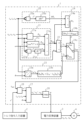
- FIG. 1 is a block diagram illustrating a hardware configuration of a control device according to a first embodiment of the present invention.
- FIG. 2 is a block diagram for explaining the operation of the control device according to the first embodiment of the present invention.
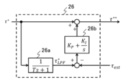
- FIG. 3 is a block diagram showing the configuration of the torque command correction unit.
- FIG. 4 is an explanatory diagram for explaining the correction of the torque command by the torque command correcting unit.
- FIG. 5 is a block diagram showing the configuration of the vector control unit.
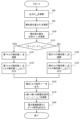
- FIG. 6 is a flowchart of a control process executed by the control device according to the first embodiment.
- FIG. 7 is a schematic diagram showing an electric vehicle equipped with a control device according to the second embodiment.
- control device 1 for the power conversion device 3 according to an embodiment of the present invention will be described with reference to Figures 1 to 6.
- FIG. 1 is a block diagram showing a schematic hardware configuration of a control device 1 according to a first embodiment of the present invention.
- the control device 1 is composed of a computer having an arithmetic device 11 such as a CPU (Central Processing Unit), MPU (Micro Processing Unit), DSP (Digital Signal Processor), etc., a non-volatile memory 12 such as a ROM (Read Only Memory), flash memory, or hard disk drive, a volatile memory 13 known as a RAM (Random Access Memory), an input/output interface 14, and other peripheral circuits.
- arithmetic device 11 may be an ASIC (application specific integrated circuit), an FPGA (field programmable gate array), etc.
- the non-volatile memory 12 stores programs capable of executing various calculations.
- the non-volatile memory 12 is a storage medium (storage device) capable of reading programs that realize the functions of this embodiment.
- the volatile memory 13 is a storage medium (storage device) that temporarily stores the results of calculations by the calculation device 11 and signals input from the input/output interface 14.
- the calculation device 11 is a device that expands the programs stored in the non-volatile memory 12 into the volatile memory 13 and executes calculations, and performs predetermined calculation processing on data taken from the input/output interface 14, the non-volatile memory 12, and the volatile memory 13 in accordance with the programs.
- the control device 1 is connected to a torque command input device 2 and a power conversion device 3.
- the torque command input device 2 is a device that uses the control device 1 to drive the electric motor 4 with a desired torque.
- the power conversion device 3 is a device that drives the electric motor 4.
- the torque command input device 2 outputs a torque command, which will be described later, to the control device 1.
- the control device 1 outputs a number of gate signals g, which will be described later, to the power conversion device 3 based on the torque command input from the torque command input device 2.
- the power conversion device 3 drives the electric motor 4 based on the multiple gate signals g input from the control device 1.
- the input section of the input/output interface 14 converts signals input from various devices (such as the torque command input device 2) into data that can be calculated by the calculation device 11.
- the output section of the input/output interface 14 generates an output signal according to the calculation result in the calculation device 11, and outputs the signal to various devices (such as the power conversion device 3).
- FIG. 2 is a block diagram for explaining the operation of the control device 1 according to the first embodiment of the present invention.
- the control device 1 includes a motor output calculation unit 21, a first torque estimation unit 22, a second torque estimation unit 23, a switching unit 24, a loss change amount calculation unit 25, a torque command correction unit 26, a vector control unit 27, and a PWM control unit 28.
- These components are supplied with the U-, V-, and W-phase voltages vu , vv , and vw of the power conversion device 3, the U-, V-, and W-phase currents iu , iv , and iw of the power conversion device 3, the frequency ⁇ of the motor 4, and the rotor phase ⁇ of the motor 4.
- These values are current values acquired from the power conversion device 3 and the motor 4 by sensors (not shown) or the like at any time, and are supplied to the components of the control device 1.
- the motor output calculation unit 21 includes an inner product calculation unit 21 a, an addition/subtraction unit 21 b, a loss calculation unit 21 c, an inner product calculation unit 21 d, and a copper loss calculation unit 21 e.
- the motor output calculation unit 21 calculates an output P out of the motor 4 based on U-, V-, and W-phase voltages v u , v v , and v w of the power conversion device 3, U-, V-, and W-phase currents i u , iv , and i w of the power conversion device 3, and a frequency ⁇ of the motor 4.
- the inner product calculation unit 21a calculates the input P in of the motor 4, which is the inner product of the U-phase, V-phase, and W-phase voltages v u , v v , and v w of the power conversion device 3 and the U-phase, V-phase, and W-phase currents i u , i v , and i w of the power conversion device 3.
- the loss calculation unit 21c calculates the loss P LI expressed as "a ⁇ m i n +b" using coefficients a and b. In other words, the loss P LI is a value obtained by adding an offset value b to the product of the current multiplier i n and the frequency multiplier ⁇ m of the motor 4.
- the loss P LI is, for example, an eddy current loss or a hysteresis loss.
- the loss PLI is, for example, an eddy current loss or a hysteresis loss.
- a and b at this time are identified by, for example, calibration.
- Other possible examples of the loss PLI include AC copper loss and mechanical loss, and a, b, m, and n are calibrated in advance so that the error between "a ⁇ m i n +b" and the actual measurement value is minimized.
- Calibration is performed, for example, by attaching sensors capable of measuring losses to the power conversion device 3, the motor 4, etc., changing the frequency ⁇ of the motor 4 and the U-phase, V-phase, and W-phase currents iu , iv , and iw of the power conversion device 3, respectively, to measure the losses, and searching for a, b, m, and n that minimize the difference from the actual measurement value.
- the motor output calculation unit 21 thereby calculates some or all of the eddy current loss, hysteresis loss, AC copper loss, and mechanical loss as PLI .
- R is the winding resistance value of the motor 4.
- the addition and subtraction unit 21b calculates the output Pout of the motor 4 by the following equation (1).
- P out P in -P LI -P LR ...(1) Equation (1) holds true because the gap between the input and output to the motor 4 is the loss of the motor 4 .
- the second torque estimation unit 23 includes a three-phase to two-phase conversion unit 23a and a torque model 3b.
- the second torque estimation unit 23 calculates a second torque estimation value ⁇ 2 from U-phase, V-phase and W-phase currents iu , iv and iw of the power conversion device 3 and a rotor phase ⁇ of the electric motor 4.
- the three-phase to two-phase conversion unit 23a converts the U-phase, V-phase and W-phase currents iu , iv and iw of the power conversion device 3 into d-axis and q-axis currents id and iq using the rotor phase ⁇ of the electric motor 4.
- the second torque estimation unit 23 calculates the second torque estimation value ⁇ 2 using the torque model 3b expressed by the following equation (3).
- ⁇ 2 P m (K e + (L d - L q ) i d ) i q ... (3)
- Pm is the number of pole pairs
- K e is the induced voltage coefficient
- L d is the d-axis inductance
- L q is the q-axis inductance.
- the second torque estimate ⁇ 2 is a value calculated by performing three-phase to two-phase conversion on the U-phase, V-phase, and W-phase currents i u , iv , and i w (three-phase AC currents) of the motor 4 to d-axis and q-axis currents i d , i q using the rotor phase ⁇ of the motor 4, and then based on the d-axis and q-axis currents i d , i q , the inductances L d , L q of the motor 4, and the induced voltage coefficient K e of the motor 4.
- the switching unit 24 includes a loss change ratio calculation unit 24a, a comparison unit 24b, and a switch 24c.
- the switching unit 24 outputs either the first torque estimate value ⁇ 1 or the second torque estimate value ⁇ 2 as the torque estimate value ⁇ est .
- the loss change ratio calculation unit 24a calculates a ratio ⁇ L of the "loss change amount ⁇ P L of the electric motor 4 during temperature fluctuation" to the output P out of the electric motor 4. In the following description, this ratio ⁇ L is referred to as the loss change ratio ⁇ L .
- the comparator 24b compares the absolute value
- the switch 24c outputs the first torque estimate ⁇ 1 as the torque estimate ⁇ est when the flag F is Yes, and outputs the second torque estimate ⁇ 2 as the torque estimate ⁇ est when the flag F is No.
- the loss change amount calculation unit 25 includes an inner product calculation unit 25a and a copper loss change amount calculation unit 25b.
- the amount of loss change ⁇ P L is the product of the amount of change ⁇ R in the winding resistance value R due to the temperature change of the motor 4 and the square of the current of the motor 4, i 2.
- the winding resistance change ⁇ R is a value measured or estimated in advance and stored in the nonvolatile memory 12 or the like, and is read out from the nonvolatile memory 12 or the like as necessary.
- FIG. 3 is a block diagram showing the configuration of the torque command correction unit 26.
- the torque command correction unit 26 corrects the torque command ⁇ * based on the torque estimate value ⁇ est and outputs the corrected value as a corrected torque command ⁇ ** .
- the torque command correction unit 26 includes a low-pass filter 26a and a PI control unit 26b.
- the low-pass filter 26a with a time constant T simulates the response of torque control. Therefore, the output ⁇ LPF * of the low-pass filter 26a represents an ideal torque response.
- the torque command correction unit 26 inputs the difference between the output ⁇ LPF * of the low-pass filter 26a and the torque estimate value ⁇ est to the PI control unit 26b, adds the output to the torque command ⁇ * , and outputs it as a corrected torque command ⁇ ** . That is, the corrected torque command ⁇ ** is determined by two-degree-of-freedom control in which the torque estimate value ⁇ est is fed back and the torque command ⁇ * is fed forward.
- Fig. 4 is an explanatory diagram for explaining the correction of the torque command ⁇ * by the torque command correction unit 26.
- the horizontal axis of Fig. 4 indicates time, and the vertical axis indicates the torque value.
- the torque command correction unit 26 is disabled until time t1 shown in Fig. 4, and is enabled after time t1 . It is also assumed that the torque command ⁇ * is constant over the entire time axis shown in Fig. 4.
- the torque estimate ⁇ est (and the actual torque ⁇ of the electric motor 4) is indicated by a solid line, and the corrected torque command ⁇ ** is indicated by a dashed line.
- the torque command corrector 26 is disabled until time t1 , so the torque command ⁇ * and the corrected torque command ⁇ ** match until time t1 .
- the output ⁇ LPF * of the low-pass filter 26a is greater than the torque estimate ⁇ est, so the output of the PI control unit 26b becomes positive, and the corrected torque command ⁇ ** increases.
- the vector control unit 27 calculates U-phase, V-phase, and W-phase voltage commands vu*, vv*, and vw * based on the correction torque command ⁇ ** , the U-phase, V-phase, and W-phase currents iu , iv , and iw of the power conversion device 3 , and the rotor phase ⁇ of the electric motor 4.
- the vector control unit 27 includes a torque/current command conversion unit 27a, a current control unit 27b, a three-phase to two-phase conversion unit 27c, and a two-phase to three-phase conversion unit 27d.
- the torque/current command conversion unit 27a converts the correction torque command ⁇ ** into d-axis/q-axis current commands i d * , i q * .
- the three-phase/two-phase conversion unit 27c converts the U-phase/V-phase/W-phase currents i u , i v , and i w of the power conversion device 3 into d-axis/q-axis currents i d , i q using the rotor phase ⁇ of the motor 4.
- the current control unit 27b calculates d-axis/q-axis voltage commands v d * , v q * based on the d-axis/q-axis current commands i d * , i q * and the d-axis/q-axis currents i d , i q .
- the two-phase/three-phase conversion unit 27d converts the d-axis/q-axis voltage commands v d * , v q * into U-phase/V-phase/W-phase voltage commands v u * , v v * , and v w * using the rotor phase ⁇ of the motor 4.
- the PWM control unit 28 outputs a plurality of gate signals g (i.e., PWM control signals) to the power conversion device 3 based on the U-phase, V-phase, and W-phase voltage commands vu * , vv * , and vw * , thereby controlling the power conversion device 3.
- U-phase, V-phase, and W-phase voltages vu , vv , and vw are applied to the electric motor 4, U-phase, V-phase, and W-phase currents iu , iv , and iw flow, and an actual torque ⁇ is generated.
- step S80 the motor output calculation unit 21 calculates the output P out of the motor 4 based on the U-phase, V-phase, and W-phase voltages v u , v v , and v w of the power conversion device 3, the U-phase, V-phase, and W-phase currents i u , iv , and i w of the power conversion device 3, and the frequency ⁇ of the motor 4.
- step S90 the loss change calculation unit 25 calculates the loss change amount ⁇ P L of the motor 4 during temperature fluctuation.
- step S100 the switching unit 24 calculates the ratio ⁇ L of the loss change amount using the output P out of the motor 4 calculated in step S80 and the loss change amount ⁇ P L of the motor 4 during temperature fluctuation calculated in step S90.
- step S110 the switching unit 24 compares the absolute value
- step S120 the first torque estimation unit 22 calculates the first torque estimate value ⁇ 1 by the above-mentioned equation (2).
- step S130 the switching unit 24 outputs the first torque estimate value ⁇ 1 calculated in step S120 as the torque estimate value ⁇ est . Thereafter, the process proceeds to step S160.
- step S140 the second torque estimation unit 23 calculates the second torque estimation value ⁇ 2 by the above-mentioned equation (3).
- step S150 the switching unit 24 outputs the second torque estimation value ⁇ 2 calculated in step S140 as the torque estimation value ⁇ est . Thereafter, the process proceeds to step S160.
- step S160 the torque command correction unit 26 corrects the torque command ⁇ * based on the torque estimation value ⁇ est output in step S120 or step S140, and outputs the corrected value as a corrected torque command ⁇ ** .
- step S170 the vector control unit 27 calculates U-phase, V-phase, and W-phase voltage commands vu * , vv * , and vw * based on the corrected torque command ⁇ ** output in step S160, the U-phase, V-phase, and W-phase currents iu, iv , and iw of the power conversion device 3, and the rotor phase ⁇ of the motor 4.
- step S180 the PWM control unit 28 outputs a plurality of gate signals g to the power conversion device 3 based on the U -phase, V-phase, and W-phase voltage commands vu * , vv * , and vw * calculated in step S170, thereby controlling the power conversion device 3.
- the torque error ratio ⁇ will eventually become zero by the torque command correction unit 26. Since the calculation of the second torque estimation value ⁇ 2 by the second torque estimator 23 is affected by a detection error of the rotor phase ⁇ of the electric motor 4, it is desirable to use the first torque estimation value ⁇ 1 calculated by the first torque estimator 22 as much as possible. However, since the calculation of the first torque estimation value ⁇ 1 by the first torque estimator 22 is affected by temperature fluctuations in the winding resistance value R used in the calculation of the copper loss P LR , the torque error ratio ⁇ does not become zero. In other words, an error due to temperature fluctuations occurs in the first torque estimation value ⁇ 1. In other words, a non-zero torque error ratio ⁇ occurs in the first torque estimation value ⁇ 1 due to temperature fluctuations.
- the control device 1 suppresses the torque error ratio ⁇ due to temperature fluctuation to at most the allowable torque error ratio ⁇ MAX by the switching unit 24 and the loss change amount calculation unit 25.
- the principle of this operation is as follows.
- (Operation Principle 1) The first torque estimator 22 is applied by the comparator 24b and the switch 24c only when "
- (Operation Principle 2) The torque error ratio ⁇ is expressed by the following equation (5) due to the effect of the torque command corrector 26.
- " ⁇ est ⁇ 1 " within the application range of the first torque estimation section 22.
- the first torque estimator 22 is applied only when "
- the second torque estimator 23 is affected by the detection error of the rotor phase ⁇ of the motor 4, but is not affected by the winding resistance fluctuation ⁇ R due to temperature fluctuations, and is robust against temperature fluctuations.
- the calculation device 11 calculates the output P out of the motor 4, calculates the loss change amount ⁇ P L due to a temperature change of the motor 4, and if the absolute value
- the calculation device 11 sets the inner product (output of the power conversion device 3) of the U-phase, V- phase , and W-phase voltages vu , vv, and vw of the power conversion device 3 and the U-phase, V-phase, and W-phase currents iu , iv , and iw of the power conversion device 3 as the input Pin of the motor 4, and sets the value obtained by subtracting the loss PLI of the motor 4 from the input Pin of the motor 4 as the output Pout of the motor 4. In this manner, the output Pout of the motor 4 can be calculated taking into account losses of the motor 4 such as copper loss.
- the calculation device 11 calculates the loss change amount ⁇ P L based on the product a ⁇ m i n of the current multiplier i n and the frequency multiplier ⁇ m of the motor 4 plus the offset value b. In this way, the copper loss, which accounts for a large part of the influence of temperature fluctuations, can be calculated with a simple calculation. Since only a simple calculation is required, the amount of calculation is reduced, and power consumption can be reduced.
- the calculation device 11 determines the loss change amount ⁇ P L as the product of the winding resistance variation ⁇ R, which is the amount of change in the winding resistance value R due to a temperature change of the motor 4, and the square i2 of the current of the motor 4. Since it is configured in this way, the loss change amount ⁇ P L can be calculated with a small amount of calculation.
- the calculation device 11 sets the first torque estimated value ⁇ 1 to a value obtained by dividing the output P out of the electric motor 4 by the frequency ⁇ (rotation speed) of the electric motor 4. Since this is done, when the temperature does not fluctuate greatly, the first torque estimator 22 can stably obtain a highly accurate torque estimated value.
- the calculation device 11 performs three-phase to two-phase conversion of the U-phase, V-phase and W-phase currents iu , iv , iw (three-phase AC currents) of the power conversion device 3 of the motor 4 into d-axis and q-axis currents id , iq using the rotor phase ⁇ of the motor 4 , and calculates the second torque estimation value ⁇ 2 based on the d-axis and q-axis currents id, iq, the d-axis inductance Ld and q-axis inductance Lq of the motor 4, and the induced voltage coefficient Ke of the motor 4. Since this is done in this manner, when temperature fluctuations are severe, the second torque estimator 23 can stably obtain a highly accurate torque estimation value.
- the calculation device 11 corrects the torque command ⁇ * input to the control device 1 based on the torque estimate value ⁇ est of the electric motor 4, and outputs a gate signal g (PWM control signal) to the power conversion device 3 based on the corrected torque command ⁇ ** . In this manner, the power conversion device 3 can be stably controlled to a desired torque.
- the calculation device 11 is a two-degree-of-freedom control system in which the torque estimation value ⁇ est is fed back and the torque command ⁇ * is fed forward. As a result, even if the first torque estimator 22 and the second torque estimator 23 are switched, the estimation result does not become unstable and high estimation accuracy can be steadily maintained.
- control device according to the second embodiment of the present invention will be described with reference to FIG. 7. Note that the same reference symbols are used for configurations that are the same as or equivalent to those described in the first embodiment, and differences will be mainly described.
- FIG. 7 is a schematic diagram showing an electric vehicle 200 equipped with a control device 100 according to the second embodiment.
- the electric vehicle 200 is an electric vehicle that uses an electric motor 4 as a drive source. That is, the electric vehicle 200 has four electric motors 4, and each electric motor 4 is connected to the axles of four wheels 201 equipped on the electric vehicle 200. For each of the four electric motors 4, a corresponding control device 100 and power conversion device 3 are provided.
- the electric vehicle 200 includes a control device (hereinafter also referred to as an electric vehicle control device) 202 that controls each part of the electric vehicle 200.
- the electric vehicle control device 202 corresponds to the torque command input device 2 described in the first embodiment. That is, the electric vehicle control device 202 outputs torque commands ⁇ 1 * , ⁇ 2 * , ⁇ 3 * , and ⁇ 4 * for accelerating and decelerating the electric vehicle 200 to each of the four control devices 100. Since the electric vehicle 200 is operated under a wide range of conditions from low speed to high speed, the temperature of the electric motor 4 constantly fluctuates, but the control device 100 according to the second embodiment can suppress the torque error ratio ⁇ to the allowable torque error ratio ⁇ MAX or less. Therefore, the electric vehicle 200 can be accelerated and decelerated stably.
- the operation of the torque command correction unit 26 may be different from that described in FIG. 3.
- the torque estimation value ⁇ est may be directly used as the corrected torque command ⁇ ** .
- the output may oscillate when switching between the first torque estimation unit 22 and the second torque estimation unit 23, and may become unstable in a transient state.
- the input P in of the motor 4 may be obtained by the product of the input to the power conversion device 3 and the power conversion efficiency by the power conversion device 3, instead of the dot product of the U-phase, V-phase, and W-phase voltages vu, vv, and vw of the power conversion device 3 and the U-phase, V-phase, and W-phase currents iu, iv, and iw of the power conversion device 3.
- 1,100...control device 2...torque command input device, 3...power conversion device, 4...electric motor, 11...arithmetic device, 12...non-volatile memory, 13...volatile memory, 14...input/output interface, 21...motor output calculation unit, 22...first torque estimation unit, 23...second torque estimation unit, 24...switching unit, 25...loss change amount calculation unit, 26...torque command correction unit, 27...vector control unit, 28...PWM control unit, 200...electric vehicle, 201...wheel, 202...electric vehicle control device
Landscapes
- Engineering & Computer Science (AREA)
- Power Engineering (AREA)
- Control Of Ac Motors In General (AREA)
Abstract
Description
Pout = Pin-PLI-PLR …(1)
式(1)は、電動機4への入出力のギャップが電動機4の損失であることから成り立つ。
τ1 = Pout / ω …(2)
式(2)は電動機4の出力Poutがトルクと周波数の積であることから成り立つ。
τ2 = Pm (Ke+(Ld ‐ Lq)id )iq …(3)
ここで、Pmは極対数、Keは誘起電圧係数、Ldはd軸インダクタンス、Lqはq軸インダクタンスである。つまり第2トルク推定値τ2は、電動機4の回転子位相θを用いて電動機4のU相・V相・W相電流iu、iv、iw(三相交流電流)をd軸・q軸電流id、iqに三相二相変換し、その後、d軸・q軸電流id、iqと電動機4のインダクタンスLd、Lqと電動機4の誘起電圧係数Keとに基づいて演算される値である。
Δτ = (τ ‐ τ*)/τ* …(4)
このため、トルク推定に誤差がない限り、トルク誤差比率Δτはトルク指令補正部26の補正によりいずれゼロで安定する。
(動作原理1)比較部24bおよび切替器24cによって、「|ΔτL| < ΔτMAX」の場合に限り第1トルク推定部22が適用される。
(動作原理2)トルク誤差比率Δτは、トルク指令補正部26の効果によって、次式(5)で表される。
Δτ = (τ-τ*)/τ* = (τ-τest)/τest …(5)
ここで、第1トルク推定部22の適用範囲では「τest = τ1」である。また、上式(1)、(2)より次式(6)が成り立つ。
τest = τ1 = (Pin-PLI-PLR)/ω …(6)
同様に、実トルクτについては次式(7)が成り立つ。
τ = (Pin-PLI-PLR-ΔPL)/ω …(7)
式(5)に式(6)および式(7)を代入すると、次式(8)が得られる。
Δτ = (-ΔPL)/(Pin-PLI-PLR) = -ΔPL/POUT …(8)
以上より、「Δτ=-ΔτL」であることが分かる。
(動作原理3)上記の(1)および(2)より、「|ΔτL| < ΔτMAX」すなわち「|Δτ| < ΔτMAX」の場合に限り、第1トルク推定部22が適用される。ゆえに第1トルク推定部22の適用時、温度変動によるトルク誤差比率Δτが許容トルク誤差比率ΔτMAXを超えることはなく、もし超える場合には第2トルク推定部23に自動的に切り替わる。第2トルク推定部23は電動機4の回転子位相θの検出誤差の影響は受けるが、温度変動による巻線抵抗変動ΔRの影響を受けることはなく、温度変動に対してロバストとなる。
トルク指令補正部26の動作は、図3で説明したものと異なっていてもよい。例えばトルク推定値τestをそのまま補正トルク指令τ**としてもよい。この場合でも、定常的には精度よくトルク推定を行うことができる。ただし、第1トルク推定部22と第2トルク推定部23との切替時に出力が振動し、過渡的には不安定になるおそれがある。
電動機4の入力Pinを、電力変換装置3のU相・V相・W相電圧vu、vv、vwと電力変換装置3のU相・V相・W相電流iu、iv、iwとの内積ではなく、電力変換装置3の入力と電力変換装置3による電力の変換効率との積により求めてもよい。
Claims (9)
- 電動機を駆動する電力変換装置の制御装置であって、
演算装置を備え、
前記演算装置は、
前記電動機の出力を演算し、
前記電動機の温度変化による損失変化量を演算し、
前記電動機の出力に対する前記損失変化量の比率が前記電動機の許容トルク誤差比率よりも小さい場合には、前記電動機の出力と前記電動機の回転速度とに基づく第1トルク推定値を前記電動機のトルク推定値とし、それ以外の場合には、前記電動機の電流と前記電動機の回転子位相とに基づく第2トルク推定値を前記電動機のトルク推定値とする、
電力変換装置の制御装置。 - 請求項1に記載の電力変換装置の制御装置において、
前記演算装置は、前記電力変換装置の入力と変換効率との積、または前記電力変換装置の出力を前記電動機の入力とし、前記電動機の入力から前記電動機の損失を差し引いた値を前記電動機の出力とする、
電力変換装置の制御装置。 - 請求項2に記載の電力変換装置の制御装置において、
前記演算装置は、前記電動機の電流の乗数と周波数の乗数との積にオフセット値を加算した値に基づいて前記損失変化量を演算する、
電力変換装置の制御装置。 - 請求項1に記載の電力変換装置の制御装置において、
前記演算装置は、前記電動機の温度変化による巻線抵抗値の変化量と前記電動機の電流の2乗との積を前記損失変化量とする、
電力変換装置の制御装置。 - 請求項1に記載の電力変換装置の制御装置において、
前記演算装置は、前記電動機の出力を前記電動機の回転速度で除算した値を前記第1トルク推定値とする、
電力変換装置の制御装置。 - 請求項1に記載の電力変換装置の制御装置において、
前記演算装置は、前記電動機の回転子位相を用いて前記電動機の三相交流電流をd軸・q軸電流に三相二相変換し、当該d軸・q軸電流と前記電動機のインダクタンスと前記電動機の誘起電圧係数とに基づいて前記第2トルク推定値を演算する、
電力変換装置の制御装置。 - 請求項1に記載の電力変換装置の制御装置において、
前記演算装置は、前記制御装置に入力されたトルク指令を前記電動機のトルク推定値に基づいて補正し、補正した前記トルク指令に基づいて前記電力変換装置にPWM制御信号を出力する、
電力変換装置の制御装置。 - 請求項7に記載の電力変換装置の制御装置において、
前記演算装置は、前記トルク推定値をフィードバック、前記トルク指令をフィードフォワードとする二自由度制御系である、
電力変換装置の制御装置。 - 請求項1に記載の電力変換装置の制御装置において、
前記電動機を駆動源とする電動車の制御装置からトルク指令が入力される、
電力変換装置の制御装置。
Priority Applications (2)
| Application Number | Priority Date | Filing Date | Title |
|---|---|---|---|
| EP24819078.7A EP4727002A1 (en) | 2023-06-08 | 2024-05-09 | Control apparatus for electric power conversion device |
| CN202480011004.1A CN120642204A (zh) | 2023-06-08 | 2024-05-09 | 电力转换装置的控制装置 |
Applications Claiming Priority (2)
| Application Number | Priority Date | Filing Date | Title |
|---|---|---|---|
| JP2023094987A JP2024176449A (ja) | 2023-06-08 | 2023-06-08 | 電力変換装置の制御装置 |
| JP2023-094987 | 2023-06-08 |
Publications (1)
| Publication Number | Publication Date |
|---|---|
| WO2024252841A1 true WO2024252841A1 (ja) | 2024-12-12 |
Family
ID=93795277
Family Applications (1)
| Application Number | Title | Priority Date | Filing Date |
|---|---|---|---|
| PCT/JP2024/017261 Ceased WO2024252841A1 (ja) | 2023-06-08 | 2024-05-09 | 電力変換装置の制御装置 |
Country Status (4)
| Country | Link |
|---|---|
| EP (1) | EP4727002A1 (ja) |
| JP (1) | JP2024176449A (ja) |
| CN (1) | CN120642204A (ja) |
| WO (1) | WO2024252841A1 (ja) |
Citations (5)
| Publication number | Priority date | Publication date | Assignee | Title |
|---|---|---|---|---|
| JP2002233199A (ja) | 2001-02-05 | 2002-08-16 | Railway Technical Res Inst | 永久磁石同期電動機の制御装置 |
| JP2015133891A (ja) * | 2014-01-13 | 2015-07-23 | 日産自動車株式会社 | 同期電動機のトルク推定システム |
| JP2016187250A (ja) * | 2015-03-27 | 2016-10-27 | 三菱電機株式会社 | 電動機制御装置 |
| JP2018093642A (ja) * | 2016-12-05 | 2018-06-14 | 東洋電機製造株式会社 | 温度推定装置 |
| JP2020167870A (ja) * | 2019-03-29 | 2020-10-08 | 株式会社日立製作所 | 永久磁石同期機の駆動装置、永久磁石同期機のトルク補償方法、および電気車 |
-
2023
- 2023-06-08 JP JP2023094987A patent/JP2024176449A/ja active Pending
-
2024
- 2024-05-09 EP EP24819078.7A patent/EP4727002A1/en active Pending
- 2024-05-09 CN CN202480011004.1A patent/CN120642204A/zh active Pending
- 2024-05-09 WO PCT/JP2024/017261 patent/WO2024252841A1/ja not_active Ceased
Patent Citations (5)
| Publication number | Priority date | Publication date | Assignee | Title |
|---|---|---|---|---|
| JP2002233199A (ja) | 2001-02-05 | 2002-08-16 | Railway Technical Res Inst | 永久磁石同期電動機の制御装置 |
| JP2015133891A (ja) * | 2014-01-13 | 2015-07-23 | 日産自動車株式会社 | 同期電動機のトルク推定システム |
| JP2016187250A (ja) * | 2015-03-27 | 2016-10-27 | 三菱電機株式会社 | 電動機制御装置 |
| JP2018093642A (ja) * | 2016-12-05 | 2018-06-14 | 東洋電機製造株式会社 | 温度推定装置 |
| JP2020167870A (ja) * | 2019-03-29 | 2020-10-08 | 株式会社日立製作所 | 永久磁石同期機の駆動装置、永久磁石同期機のトルク補償方法、および電気車 |
Also Published As
| Publication number | Publication date |
|---|---|
| JP2024176449A (ja) | 2024-12-19 |
| CN120642204A (zh) | 2025-09-12 |
| EP4727002A1 (en) | 2026-04-15 |
Similar Documents
| Publication | Publication Date | Title |
|---|---|---|
| JP6667407B2 (ja) | 制御装置 | |
| JP4881635B2 (ja) | 永久磁石モータのベクトル制御装置 | |
| JP4730073B2 (ja) | 永久磁石同期モータのベクトル制御装置,インバータモジュール、及び永久磁石同期電動機モータ定数表示システム | |
| JP2009142116A (ja) | 永久磁石モータの位置センサレス制御装置 | |
| EP3537601B1 (en) | Motor control method | |
| JPWO2016125567A1 (ja) | 同期機制御装置および同期機の永久磁石温度推定方法 | |
| JP2010200430A (ja) | 電動機の駆動制御装置 | |
| CN104779872B (zh) | 同步电动机的控制装置及控制方法 | |
| JP6358834B2 (ja) | ベクトル制御装置、それを組み込んだインバータ及びそれを組み込んだインバータとモータとのセット装置 | |
| US20140232308A1 (en) | Inverter apparatus | |
| JP2019050684A (ja) | パワーステアリング装置の制御装置 | |
| JP7151872B2 (ja) | 永久磁石同期機の制御装置 | |
| JP2000037098A (ja) | 速度センサレスベクトル制御を用いた電力変換装置 | |
| JP5050387B2 (ja) | モーター制御装置 | |
| JP4650110B2 (ja) | 電動機の制御装置 | |
| JP2024176449A (ja) | 電力変換装置の制御装置 | |
| JP5996485B2 (ja) | モータの駆動制御装置 | |
| JP7627204B2 (ja) | 電力変換装置 | |
| JP2007135345A (ja) | 磁石モータ制御装置 | |
| WO2024048258A1 (ja) | モータ制御装置 | |
| JP2010268567A (ja) | 交流電動機の制御装置 | |
| JP4687104B2 (ja) | 永久磁石型回転電動機の制御装置およびその方法 | |
| JP6711170B2 (ja) | モータ制御装置 | |
| JP7819556B2 (ja) | モータ制御方法及びモータ制御装置 | |
| JP2009100600A (ja) | インバータ制御装置とその制御方法 |
Legal Events
| Date | Code | Title | Description |
|---|---|---|---|
| 121 | Ep: the epo has been informed by wipo that ep was designated in this application |
Ref document number: 24819078 Country of ref document: EP Kind code of ref document: A1 |
|
| WWE | Wipo information: entry into national phase |
Ref document number: 202480011004.1 Country of ref document: CN |
|
| WWP | Wipo information: published in national office |
Ref document number: 202480011004.1 Country of ref document: CN |
|
| WWE | Wipo information: entry into national phase |
Ref document number: 2024819078 Country of ref document: EP |
|
| NENP | Non-entry into the national phase |
Ref country code: DE |
|
| ENP | Entry into the national phase |
Ref document number: 2024819078 Country of ref document: EP Effective date: 20260108 |
|
| ENP | Entry into the national phase |
Ref document number: 2024819078 Country of ref document: EP Effective date: 20260108 |
|
| ENP | Entry into the national phase |
Ref document number: 2024819078 Country of ref document: EP Effective date: 20260108 |
|
| ENP | Entry into the national phase |
Ref document number: 2024819078 Country of ref document: EP Effective date: 20260108 |
|
| ENP | Entry into the national phase |
Ref document number: 2024819078 Country of ref document: EP Effective date: 20260108 |