WO2024252724A1 - 清掃システム - Google Patents
清掃システム Download PDFInfo
- Publication number
- WO2024252724A1 WO2024252724A1 PCT/JP2024/003431 JP2024003431W WO2024252724A1 WO 2024252724 A1 WO2024252724 A1 WO 2024252724A1 JP 2024003431 W JP2024003431 W JP 2024003431W WO 2024252724 A1 WO2024252724 A1 WO 2024252724A1
- Authority
- WO
- WIPO (PCT)
- Prior art keywords
- cleaning
- camera
- vehicle
- travel
- running
- Prior art date
- Legal status (The legal status is an assumption and is not a legal conclusion. Google has not performed a legal analysis and makes no representation as to the accuracy of the status listed.)
- Ceased
Links
Images

Classifications
-
- B—PERFORMING OPERATIONS; TRANSPORTING
- B08—CLEANING
- B08B—CLEANING IN GENERAL; PREVENTION OF FOULING IN GENERAL
- B08B5/00—Cleaning by methods involving the use of air flow or gas flow
- B08B5/04—Cleaning by suction, with or without auxiliary action
-
- B—PERFORMING OPERATIONS; TRANSPORTING
- B65—CONVEYING; PACKING; STORING; HANDLING THIN OR FILAMENTARY MATERIAL
- B65G—TRANSPORT OR STORAGE DEVICES, e.g. CONVEYORS FOR LOADING OR TIPPING, SHOP CONVEYOR SYSTEMS OR PNEUMATIC TUBE CONVEYORS
- B65G1/00—Storing articles, individually or in orderly arrangement, in warehouses or magazines
- B65G1/02—Storage devices
- B65G1/04—Storage devices mechanical
Definitions
- the present invention relates to a cleaning system, and in particular to a cleaning system for cleaning a track along which a transport vehicle that transports goods travels.
- Patent Document 1 JP Patent Publication No. 2022-180403 (Patent Document 1) describes a robot service device.
- This robot service device is used in a robot retrieval system in which a robot handles loaded items, and is configured to assist the robot in handling multiple operable loaded items.
- the robot service device is configured to be able to travel vertically and horizontally on a grid on which the robot travels, and to be able to move to any position on the grid.
- This robot service device is also equipped with a cleaning means and a camera means.
- the present invention therefore aims to provide a cleaning system that can accurately grasp the condition of the track on which the transport vehicle travels and can effectively clean the track.
- the present invention is a cleaning system for cleaning a track along which a transport vehicle for transporting goods travels, and is characterized by having a cleaning vehicle that travels along the track, a cleaning device mounted on the cleaning vehicle and cleaning the running surface of the running track with which the wheels of the transport vehicle come into contact, a front camera mounted on the cleaning vehicle and taking pictures of the running surface on the forward side in the running direction, a rear camera mounted on the cleaning vehicle and taking pictures of the running surface on the rear side in the running direction, and a recording device that records the forward image taken by the front camera and the rear image taken by the rear camera in association with each other.
- the front camera photographs the running surface on the forward side in the running direction
- the rear camera photographs the running surface on the rear side in the running direction
- the condition of the running surface of the running track can be accurately grasped and it can be accurately determined whether cleaning is necessary.
- the recording device records the front image taken by the front camera and the rear image taken by the rear camera in association with each other, so when the cleaning vehicle cleans while traveling, the condition of the running surface before and after cleaning can be easily compared and the results of the cleaning can be accurately evaluated. As a result, the running surface can be effectively cleaned by the cleaning vehicle.
- the cleaning device cleans between the front and rear cameras, so the cleaning device itself does not enter the field of view of the front and rear cameras.
- the cleaning device does not create blind spots on the road surface, and the front and rear cameras can see the entire road surface in front and rear, allowing the condition of the road surface to be accurately grasped.
- the running track on which the transport vehicle travels has running surfaces on both sides of the width of the vehicle
- the front camera is configured to simultaneously capture images of the running surfaces on both sides of the width of the vehicle on the forward side in the running direction
- the rear camera is configured to simultaneously capture images of the running surfaces on both sides of the width of the vehicle on the rear side in the running direction.
- the present invention simultaneously captures two driving surfaces, one in front and one in rear, using the front camera and the other in rear, making it possible to grasp the condition of many driving surfaces using a small number of cameras.
- the vehicle further includes a front light that irradiates light onto the traveling surface photographed by the front camera, and a rear light that irradiates light onto the traveling surface photographed by the rear camera.
- the position detected by the position sensor is recorded in association with the front image and rear image, so the position on the traveling track of the images captured by the front camera and rear camera can be easily identified, and the images captured by the front camera and rear camera can be effectively used for various maintenance of the traveling track.
- ceiling transport vehicles run on a track installed near the ceiling of a building, making it difficult to visually inspect the running surface or to manually clean the running surface.
- the running surface is photographed with a front camera and a rear camera, and the running surface is cleaned with a cleaning device, making it easy to clean the running track, which is difficult to clean, and to easily understand the results of the cleaning.
- the front and rear cameras are positioned between the wheels on both sides in the width direction, so the front and rear cameras do not protrude significantly above the running surface, and the height of the cleaning vehicle above the running surface can be kept low, allowing the running track of the overhead transport vehicle to be configured compactly.
- the cleaning device is preferably disposed above the running surface of the running track and has a suction nozzle for sucking up dust on the running surface and a suction device for sucking air from the suction nozzle, and the suction device is suspended from the cleaning vehicle below the running surface.
- a suction nozzle that sucks up dust on the running surface is positioned above the running surface, and a suction device that sucks air from this suction nozzle is suspended below the running surface from the cleaning vehicle. Therefore, even if the space above the running surface is narrow, a large suction device with strong suction power can be used, ensuring sufficient cleaning power for the cleaning device.
- the cleaning system of the present invention makes it possible to accurately grasp the condition of the track on which the transport vehicle travels, and to effectively clean the track.
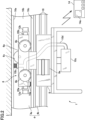
- FIG. 2 is a front view of a cleaning vehicle provided in the cleaning system according to the embodiment of the present invention.
- FIG. 2 is a side view of a cleaning vehicle provided in the cleaning system according to the embodiment of the present invention.
- Fig. 1 is a front view of a cleaning vehicle provided in a cleaning system according to an embodiment of the present invention
- Fig. 2 is a side view of the cleaning vehicle provided in the cleaning system according to an embodiment of the present invention.
- the cleaning system 1 is a system for cleaning a track on which a transport vehicle for transporting items travels.
- the transport vehicle (not shown) is a ceiling transport vehicle that travels on a track 4 provided on the ceiling surface 2.
- the cleaning vehicle 6 provided in the cleaning system 1 of this embodiment is configured to clean the track 4 while traveling on the track 4 provided on the ceiling surface 2.
- the present invention can be applied to a cleaning system for cleaning a track on which any transport vehicle other than a ceiling transport vehicle travels.
- a cleaning system 1 includes a cleaning vehicle 6, a main body 8 attached to the bottom surface of the cleaning vehicle 6, a cleaning device 10, a first camera 12a which is a front camera, a second camera 12b which is a rear camera, and a recording device 14.
- the track 4 on which the cleaning vehicle 6 of the cleaning system 1 runs has a rail 4a on which the cleaning vehicle 6 runs and brackets 4b attached to both ends of the width direction of the underside of this rail 4a.
- the rail 4a is an elongated member with a roughly rectangular cross section overall, with the center of the bottom edge cut out to open downward. That is, the rail 4a is composed of an upper surface portion 16a that is fixed along the ceiling surface 2, side surfaces 16b that extend vertically downward from both ends of the upper surface portion 16a, and a lower surface portion 16c that protrudes inward in the width direction of the rail 4a from the lower ends of each side surface portion 16b.
- the upper surface of the lower surface portion 16c is a flat surface that protrudes inward from both sides in the width direction of the cleaning vehicle 6, and constitutes the running surface of the running track 4.
- each bracket 4b is elongated members with a roughly E-shaped cross section, and are attached to the underside of each lower portion 16c of the rail 4a. That is, each bracket 4b consists of a vertical portion that extends vertically and three horizontal portions that extend horizontally from the vertical portion toward the center of the rail 4a, and a power supply line 18 is attached to the tip of each of the two lower horizontal portions.
- the cleaning vehicle 6 is a device for traveling on the track 4, and has a carriage 6a, four driven wheels 6b attached to both sides of the carriage 6a, and a drive wheel 6c (Figure 2) that protrudes upward from the center of the width of the carriage 6a.
- the carriage 6a of the cleaning vehicle 6 is placed inside the rail 4a, which has a substantially rectangular cross section, and travels inside the rail 4a in the longitudinal direction of the rail 4a.
- Two driven wheels 6b are provided on each of the widthwise ends of the carriage 6a, and these four driven wheels 6b are placed on the upper surface of each lower surface 16c of the rail 4a, and the cleaning vehicle 6 travels on each lower surface 16c. Therefore, the upper surface of each lower surface 16c forms the running surface of the running track 4, and the four driven wheels 6b of the cleaning vehicle 6 (the wheels (not shown) of the transport vehicle when the transport vehicle (not shown) travels on the running track 4) come into contact with this running surface.
- the running track 4 is provided with running surfaces located on both sides of the carriage 6a, and each driven wheel 6b travels on these running surfaces.
- the cleaning vehicle 6 has only one drive wheel 6c at the center of the width of the carriage 6a, and is provided so as to protrude upward from the carriage 6a. That is, the drive wheel 6c is biased upward from the carriage 6a and pressed against the lower surface of the upper surface 16a of the rail 4a.
- the drive wheel 6c is rotated by a motor (not shown) built into the carriage 6a, causing the cleaning vehicle 6 to run along the rail 4a.
- the cleaning vehicle 6 in this embodiment is configured to run by rotating the drive wheel 6c pressed against the upper surface 16a of the rail 4a, but the present invention can also be configured so that the vehicle runs by rotating a wheel placed on the running surface.
- the main body 8 is attached to the bottom surface of the carriage 6a of the cleaning vehicle 6, and passes between the bottom surfaces 16c of the rails 4a, extending below the track 4.
- a power supply coil 8a is attached to each side of the main body 8, and the cleaning vehicle 6 is configured to receive power in a non-contact manner from a power supply line 18 attached to the bracket 4b.
- Each power supply coil 8a is configured with a roughly E-shaped cross section and is arranged to face the bracket 4b, which also has a roughly E-shaped cross section. That is, the power supply coil 8a with an E-shaped cross section is attached to the main body 8 and is composed of a vertical section oriented vertically and three horizontal sections protruding horizontally from the vertical section. The central horizontal section of the three horizontal sections of the power supply coil 8a is located between the two power supply lines 18 attached to the bracket 4b, and has a conductor wound around it. With this configuration, when a current flows through the power supply line 18, an electromotive force is generated in the power supply coil 8a, and power is supplied to the cleaning vehicle 6 in a non-contact manner.
- the cleaning device 10 has two lower nozzles 10a, which are suction nozzles attached to the underside of the carriage 6a, an upper nozzle 10b attached to the upper surface of the carriage 6a, and a suction device 10c for sucking air from these nozzles.
- Each lower nozzle 10a is arranged above the running surface so as to face each running surface (the upper surface of each lower surface portion 16c of the rail 4a) and is configured to suck up dust on the running surface.
- the upper nozzle 10b is arranged to face the lower surface of the upper surface portion 16a of the rail 4a.
- the suction device 10c is suspended from the main body portion 8 below the cleaning vehicle 6. Therefore, in this embodiment, the suction device 10c is suspended from the cleaning vehicle 6 below the running surface.
- the suction device 10c is configured to operate with power supplied to the cleaning vehicle 6 via the power supply coil 8a.
- each lower nozzle 10a which is arranged to face each traveling surface, is attached to the underside of the front end of the carriage portion 6a of the cleaning vehicle 6, and is configured to suck up dust and the like on the traveling surface.
- the left side in FIG. 2 is called the front side of the cleaning vehicle 6, and the right side is called the rear side of the cleaning vehicle 6, but the cleaning vehicle 6 can travel both to the right and to the left in FIG. 2.
- the lower nozzle 10a has a cup-shaped member that opens downwards and a brush attached around the opening.
- the brush attached to the lower nozzle 10a is positioned so that its tip comes into contact with the traveling surface, and is configured to scrape off dust and the like on the traveling surface.
- the cup-shaped member attached to the lower nozzle 10a is also connected to a hose 10d extending from the suction device 10c, and is configured so that the inside of the cup-shaped member is under negative pressure. As a result, the dust and the like scraped off by the brush are sucked into the cup-shaped member together with air, and are collected by the suction device 10c through the hose 10d.
- the upper nozzle 10b has a cup-shaped member that opens upwards and a brush attached around the opening.
- the brush attached to the upper nozzle 10b is positioned so that its tip comes into contact with the upper surface 16a of the rail 4a, and is configured to scrape off dust and other particles adhering to the upper surface 16a.
- a hose 10d extending from the suction device 10c is also connected to the cup-shaped member attached to the upper nozzle 10b, and the dust and other particles scraped off by the brush are collected in the suction device 10c through the hose 10d.
- the first camera 12a which is a front camera, is directed forward in the direction of travel of the cleaning vehicle 6 and is configured to capture the travel surface on the forward side in the travel direction. That is, the first camera 12a is provided on the front side of the cleaning vehicle 6 and is configured to simultaneously capture the travel surface on both sides in the width direction on the forward side in the travel direction.
- the second camera 12b which is a rear camera, is directed backward in the direction of travel of the cleaning vehicle 6 and is configured to capture the travel surface on the rear side in the travel direction.
- the second camera 12b is provided on the rear side of the cleaning vehicle 6 and is configured to simultaneously capture the travel surface on both sides in the width direction on the rear side in the travel direction.
- the lower nozzle 10a of the cleaning device 10 is disposed between the first camera 12a and the second camera 12b, and the cleaning device 10 is configured to clean the traveling surface located between the first camera 12a and the second camera 12b.
- the left side in FIG. 2 is the front side of the cleaning vehicle 6, and the right side is the rear side of the cleaning vehicle 6, and the first camera 12a is called the front camera and the second camera 12b is called the rear camera, but when the cleaning vehicle 6 travels to the right in FIG. 2, the second camera 12b functions as the front camera and the first camera 12a functions as the rear camera.
- the first camera 12a and the second camera 12b are configured to capture video of the front and rear traveling surfaces while the cleaning vehicle 6 is traveling while cleaning.
- the video captured by each camera is wirelessly transmitted to the recording device 14 and recorded. Therefore, in this embodiment, the main body 8 of the cleaning vehicle 6 is equipped with a transmission unit (not shown) that transmits image information acquired by the first camera 12a and the second camera 12b to the recording device 14.
- a transmission unit not shown
- each camera captures video in this embodiment, the present invention can also be configured so that each camera captures still images of the front and rear traveling surfaces at predetermined time intervals while traveling.
- a front light 20a is provided on each side of the first camera 12a, and is adapted to irradiate light onto the traveling surface photographed by the first camera 12a.
- the front light 20a is disposed further forward of the cart section 6a than the lower nozzle 10a, so that the shadow of the lower nozzle 10a is not cast on the surface illuminated by the light from the front light 20a, and the traveling surface can be clearly photographed by the first camera 12a.
- rear lights 20b are provided on both sides of the second camera 12b, and are designed to illuminate the driving surface photographed by the second camera 12b.
- two front lights 20a and two rear lights 20b are provided on each side of the camera, but only one front light or one rear light may be provided above or below the camera.
- a position sensor 22 that detects the position at which the cleaning vehicle 6 is traveling is provided on the upper surface of the carriage portion 6a.
- This position sensor 22 is configured to read point marks 22a provided at multiple locations on the traveling track 4.
- a plurality of point marks 22a are provided at predetermined intervals on the upper surface portion 16a of the rail 4a that constitutes the traveling track 4 so as to face the position sensor 22.
- the point marks 22a position information of the point mark 22a on the running track 4 is embedded, and based on this position information, information on the position where the cleaning vehicle 6 is currently running can be obtained.
- the point marks 22a are composed of bar codes (not shown), and the position sensor 22 is composed of a bar code reader (not shown).
- information on the position on the running track 4 is embedded as a bar code.
- the cart unit 6a is equipped with a rotary encoder (not shown), which detects the rotation of the driven wheels 6b, thereby making it possible to calculate the distance traveled by the cart unit 6a.
- the cleaning vehicle 6 can accurately acquire information on the position where the cart unit 6a is currently traveling.
- the position information acquired in this way is transmitted to the recording device 14 together with the image information acquired by the first and second cameras.
- the position information of the cleaning vehicle 6 is detected by a position sensor using point marks, but the position information of the cleaning vehicle 6 can be detected by any position sensor, such as a sensor using a GPS (Global Positioning System).
- the recording device 14 is configured to record the forward image captured by the first camera 12a, the rearward image captured by the second camera 12b, and information on the location where the cleaning vehicle 6 is traveling, in association with each other.
- the images captured by the first and second cameras and information on the location of the cleaning vehicle 6 are wirelessly transmitted from the cleaning vehicle 6 to the recording device 14, and this information is recorded in the recording device 14, but the recording device 14 may also be mounted on the cleaning vehicle 6.
- the recording device 14 is also equipped with a display 14a for displaying the images captured by the first camera 12a and the second camera 12b online or offline. In this way, the recording device 14 records the forward image, the rearward image, and the position information in association with each other, so that it is possible to easily compare the state of the traveling surface before the cleaning vehicle 6 passes, captured as a forward image, with the state of the traveling surface at the same location after the cleaning vehicle 6 has passed, captured as a rearward image. This allows the results of cleaning the traveling surface by the cleaning vehicle 6 to be appropriately judged.
- the image information acquired by the first camera 12a and the second camera 12b and recorded in the recording device 14 is simultaneously presented on the display 14a in a comparable manner. That is, a forward image captured by the first camera 12a and a rearward image captured by the second camera 12b of the same location on the traveling surface as the forward image are displayed side-by-side on the display 14a. Therefore, the operator can easily recognize the results of cleaning the traveling surface by the cleaning system 1 by simply comparing the left and right images on the display 14a.
- the present invention can be configured to automatically compare images captured by the first camera 12a and the second camera 12b of the same location on the travel surface, which are recorded in the recording device 14, through image analysis, to evaluate the results of cleaning by the cleaning vehicle 6 based on the comparison, and to display the evaluation results on the display 14a.
- the present invention can be configured to display on the display 14a any positions on the travel track 4 that are determined to be insufficiently cleaned as a result of the evaluation.
- the first camera 12a photographs the running surface on the forward side in the running direction
- the second camera 12b photographs the running surface on the backward side in the running direction, so that the condition of the running surface of the running track 4 can be accurately grasped and the need for cleaning can be accurately determined.
- the recording device 14 records the forward image taken by the first camera 12a and the rear image taken by the second camera 12b in association with each other, so that when the cleaning vehicle 6 cleans while traveling, the condition of the running surface before and after cleaning can be easily compared and the results of the cleaning can be accurately evaluated. As a result, the cleaning of the running surface by the cleaning vehicle 6 can be effectively carried out.
- the cleaning device 10 cleans between the first camera 12a and the second camera 12b, so the cleaning device 10 itself does not enter the field of view of the first camera 12a and the second camera 12b.
- the cleaning device 10 does not create blind spots on the running surface, and the first camera 12a and the second camera 12b can see the entire running surface on the front and rear sides, making it possible to accurately grasp the condition of the running surface.
- the first camera 12a and the second camera 12b simultaneously capture images of two running surfaces, one on the front side and one on the rear side, so the condition of many running surfaces can be grasped with a small number of cameras.
- the front light 20a and the rear light 20b illuminate the front and rear travel surfaces, so that the first camera 12a and the second camera 12b can clearly photograph the travel surface, and the condition of the travel surface can be accurately grasped. Furthermore, because the travel surface is illuminated by the front light 20a and the rear light 20b, light can be illuminated to the required range only when photographing is performed by the first camera 12a and the second camera 12b, and energy required for illumination can be saved compared to when the entire device is illuminated at all times.
- the position detected by the position sensor 22 is recorded in association with the forward image and the rearward image, so that the positions on the traveling track of the images taken by the first camera 12a and the second camera 12b can be easily identified, and the images taken by the first camera 12a and the second camera 12b can be effectively used for various maintenance of the traveling track.
- the traveling surface is photographed by the first camera 12a and the second camera 12b, and the traveling surface is cleaned by the cleaning device 10, so that the traveling track 4 of the ceiling transport vehicle, which is difficult to clean, can be easily cleaned and the cleaning results can be easily understood.
- the first camera 12a and the second camera 12b are respectively arranged between the driven wheels 6b on both sides in the width direction, so that the first and second cameras do not protrude significantly above the running surface, and the height of the cleaning vehicle 6 above the running surface can be kept low, allowing the running track 4 of the ceiling transport vehicle to be configured compactly.
- the lower nozzle 10a that sucks up dust on the running surface is positioned above the running surface, and the suction device 10c that sucks air from this lower nozzle 10a is suspended below the running surface from the cleaning vehicle 6. Therefore, even if the space above the running surface is narrow, a large suction device 10c with strong suction power can be used, ensuring sufficient cleaning power for the cleaning device 10.
- the cleaning system of the above-mentioned embodiment of the present invention was applied to cleaning the running track on which a ceiling transport vehicle runs, but the present invention can be applied to cleaning any running track on which a transport vehicle runs, such as a running track provided on a floor surface.
- the present invention can be configured at a minimum using the components set forth in claim 1 of the claims, but the present invention can also be configured by appropriately combining these minimum components with the components set forth in the above-mentioned embodiment.
Landscapes
- Engineering & Computer Science (AREA)
- Mechanical Engineering (AREA)
- Control Of Position, Course, Altitude, Or Attitude Of Moving Bodies (AREA)
Abstract
搬送車が走行する走行軌道の状態を適確に把握することができる清掃システムを提供する。本発明は、物品を搬送する搬送車が走行する走行軌道(4)を清掃するための清掃システム(1)であって、走行軌道を走行するための清掃用走行車(6)と、この清掃用走行車に搭載され、搬送車の車輪が接触する、走行軌道の走行面を清掃するための清掃装置(10)と、清掃用走行車に搭載され、走行方向前方に向けられて走行方向前方側の走行面を撮影する前方カメラ(12a)と、清掃用走行車に搭載され、走行方向後方に向けられて走行方向後方側の走行面を撮影する後方カメラ(12b)と、前方カメラによって撮影された前方画像と、後方カメラによって撮影された後方画像と、を対応付けて記録する記録装置(14)と、を有することを特徴としている。
Description
本発明は、清掃システムに関し、特に、物品を搬送する搬送車が走行する走行軌道を清掃するための清掃システムに関する。
特開2022-180403号公報(特許文献1)には、ロボットサービス装置が記載されている。このロボットサービス装置は、ロボットが積物品の取り扱いを行うロボット取り出しシステムにおいて使用され、操作可能な複数のロボット積物品の取り扱いを助けるように構成されている。ロボットサービス装置は、ロボットが走行する格子上を縦方向及び横方向に走行することができ、格子上の任意の位置に移動することができるように構成されている。また、このロボットサービス装置には、クリーニング手段、及びカメラ手段が備えられている。
しかしながら、特許文献1記載のロボットサービス装置においては、クリーニング手段、及びカメラ手段が設けられているものの、走行する格子の状態(汚れ)や、クリーニング手段によるクリーニングの結果(除去された汚れの程度)を適切に把握することができないという問題がある。このため、特許文献1記載のロボットサービス装置では、搬送車(ロボット)が走行する走行軌道(格子)の状態に応じた、適切な清掃を行うことが難しい。
従って、本発明は、搬送車が走行する走行軌道の状態を適確に把握することができ、走行軌道の清掃を効果的に実行することができる清掃システムを提供することを目的としている。
上述した課題を解決するために、本発明は、物品を搬送する搬送車が走行する走行軌道を清掃するための清掃システムであって、走行軌道を走行する清掃用走行車と、この清掃用走行車に搭載され、搬送車の車輪が接触する、走行軌道の走行面を清掃する清掃装置と、清掃用走行車に搭載され、走行方向前方側の走行面を撮影する前方カメラと、清掃用走行車に搭載され、走行方向後方側の走行面を撮影する後方カメラと、前方カメラによって撮影された前方画像と、後方カメラによって撮影された後方画像と、を対応付けて記録する記録装置と、を有することを特徴としている。
このように構成された本発明によれば、前方カメラが走行方向前方側の走行面を撮影し、後方カメラが走行方向後方側の走行面を撮影するので、走行軌道の走行面の状態を適確に把握することができ、清掃の要否を正確に判断することができる。また、記録装置が、前方カメラによって撮影された前方画像と、後方カメラによって撮影された後方画像を対応付けて記録するので、清掃用走行車が走行しながら清掃を行った場合に、清掃前後の走行面の状態を容易に比較することができ、清掃の成果を正確に評価することができる。この結果、清掃用走行車による走行面の清掃を、効果的に実施することができる。
本発明において、好ましくは、前方カメラは清掃用走行車の前方側に設けられ、後方カメラは清掃用走行車の後方側に設けられ、清掃装置は、前方カメラと後方カメラの間に位置する走行面を清掃するように構成されている。
このように構成された本発明によれば、清掃装置が前方カメラと後方カメラの間を清掃するので、清掃装置自体が前方カメラ及び後方カメラの視界に入ることがない。この結果、清掃装置によって走行面に死角が形成されることがなく、前方カメラ及び後方カメラから、前方側、後方側の走行面全体を見通すことができ、走行面の状態を適確に把握することができる。
本発明において、好ましくは、搬送車が走行する走行軌道は搬送車の幅方向両側に走行面が設けられ、前方カメラは走行方向前方側の幅方向両側の走行面を同時に撮影し、後方カメラは走行方向後方側の幅方向両側の走行面を同時に撮影するように構成されている。
このように構成された本発明によれば、前方カメラ、後方カメラによって、前方側及び後方側の夫々2つの走行面が同時に撮影されるので、少ないカメラの台数で、多くの走行面の状態を把握することができる。
本発明において、好ましくは、さらに、前方カメラによって撮影される走行面に光を照射する前方ライトと、後方カメラによって撮影される走行面に光を照射する後方ライトと、を有する。
このように構成された本発明によれば、前方ライト及び後方ライトによって、前方及び後方の走行面に光が照射されるので、前方カメラ及び後方カメラによって走行面を鮮明に撮影することができ、走行面の状態を正確に把握することができる。また、前方ライト及び後方ライトによって走行面が照明されるので、前方カメラ及び後方カメラによって撮影を行うときだけ、必要な範囲に光を照射することができ、装置全体を常時照明する場合に比べ、照明に要するエネルギーを節約することができる。
本発明において、好ましくは、さらに、清掃用走行車が走行している位置を検出する位置センサを有し、記録装置は、位置センサによって検出された位置と、前方カメラによって撮影された前方画像と、後方カメラによって撮影された後方画像と、を関連付けて記録する。
このように構成された本発明によれば、位置センサによって検出された位置が、前方画像及び後方画像と関連付けて記録されるので、前方カメラ及び後方カメラによって撮影された画像の、走行軌道上の位置を容易に特定することができ、前方カメラ及び後方カメラによって撮影された画像を、走行軌道の様々なメンテナンスにも有効に活用することができる。
本発明において、好ましくは、搬送車は天井面に設けられた走行軌道を走行する天井搬送車であり、清掃用走行車は、天井面に設けられた走行軌道の走行面を清掃する。
一般に、天井搬送車は、建屋の天井近傍に設けられた走行軌道上を走行するため、目視による走行面の点検や、人手による走行面の清掃が困難である。上記のように構成された本発明によれば、前方カメラ及び後方カメラによって走行面を撮影し、清掃装置によって走行面を清掃するので、清掃が困難な走行軌道を容易に清掃することができると共に、清掃の結果を容易に把握することができる。
本発明において、好ましくは、走行軌道の走行面は、清掃用走行車の幅方向両側から内方に向けて夫々突出するように設けられた平面であり、清掃用走行車は幅方向両側の走行面上で夫々転がる車輪を有し、前方カメラ及び後方カメラは、幅方向において、両側の車輪の間に夫々配置されている。
このように構成された本発明によれば、前方カメラ及び後方カメラは、幅方向において、両側の車輪の間に夫々配置されているので、前方、及び後方カメラが走行面の上方に大きく突出することがなく、清掃用走行車の、走行面よりも上方の高さを低く抑えることができ、天井搬送車の走行軌道をコンパクトに構成することができる。
本発明において、好ましくは、清掃装置は、走行軌道の走行面の上側に配置され、走行面上の埃を吸い取るための吸引ノズルと、この吸引ノズルから空気を吸引するための吸引装置と、を有し、吸引装置は、清掃用走行車から走行面よりも下方に吊り下げられている。
このように構成された本発明によれば、走行面上の埃を吸い取る吸引ノズルが走行面の上側に配置され、この吸引ノズルから空気を吸引する吸引装置が清掃用走行車から走行面よりも下方に吊り下げられている。このため、走行面よりも上方のスペースが狭い場合でも、吸引力の強い大型の吸引装置を採用することができ、清掃装置に十分な清掃力を確保することができる。
本発明の清掃システムによれば、搬送車が走行する走行軌道の状態を適確に把握することができ、走行軌道の清掃を効果的に実行することができる。
次に、添付図面を参照して、本発明の実施形態による清掃システムを説明する。
図1は、本発明の実施形態による清掃システムに備えられた清掃用走行車の正面図である。図2は、本発明の実施形態による清掃システムに備えられた清掃用走行車の側面図である。
図1は、本発明の実施形態による清掃システムに備えられた清掃用走行車の正面図である。図2は、本発明の実施形態による清掃システムに備えられた清掃用走行車の側面図である。
まず、本発明の実施形態による清掃システム1は、物品を搬送する搬送車が走行する走行軌道を清掃するためのシステムである。また、本実施形態において、搬送車(図示せず)は、天井面2に設けられた走行軌道4を走行する天井搬送車である。そして、本実施形態の清掃システム1に備えられた清掃用走行車6は、天井面2に設けられた走行軌道4を走行しながら、走行軌道4を清掃するように構成されている。なお、本発明は、天井搬送車以外の任意の搬送車が走行する走行軌道を清掃するための清掃システムに適用することができる。
図1及び図2に示すように、本発明の実施形態による清掃システム1は、清掃用走行車6と、この清掃用走行車6の底面に取り付けられた本体部8と、清掃装置10と、前方カメラである第1カメラ12aと、後方カメラである第2カメラ12bと、記録装置14と、を有する。
一方、図1に示すように、清掃システム1の清掃用走行車6が走行する走行軌道4は、清掃用走行車6が走行するレール4aと、このレール4a下面の幅方向両端に取り付けられたブラケット4bと、を有する。
レール4aは、全体として略長方形断面の細長い部材であり、下辺中央部が切り欠かれて下方に向けて開放している。即ち、レール4aは、天井面2に沿って固定される上面部16aと、この上面部16aの両端から鉛直下方に向けて延びる側面部16bと、各側面部16bの下端から、レール4aの幅方向内方に向けて突出する下面部16cから構成されている。なお、後述するように、下面部16cの上側の面は、清掃用走行車6の幅方向両側から内方に向けて夫々突出するように設けられた平面であり、走行軌道4の走行面を構成する。
ブラケット4bは、略E字型断面の細長い部材であり、レール4aの各下面部16cの下側面に夫々取り付けられている。即ち、各ブラケット4bは、鉛直方向に延びる鉛直部と、この鉛直部からレール4aの中央へ向けて水平方向に延びる3つの水平部からなり、下側の2つの水平部の先端には、給電線18が夫々取り付けられている。
清掃用走行車6は、走行軌道4上を走行するための装置であり、台車部6aと、この台車部6aの両側面に夫々取り付けられた車輪である4つの従動輪6bと、台車部6aの幅方向中央から上方に突出するように設けられた駆動輪6c(図2)と、を有する。
清掃用走行車6の台車部6aは、略長方形断面のレール4aの内側に配置され、レール4aの内部をレール4aの長手方向に走行する。台車部6aの幅方向両端には、夫々2つずつ従動輪6bが設けられており、これら4つの従動輪6bは、レール4aの各下面部16cの上側の面に載せられ、清掃用走行車6は各下面部16c上を走行する。従って、各下面部16cの上側の面は走行軌道4の走行面を構成し、この走行面に清掃用走行車6の4つの従動輪6b(搬送車(図示せず)が走行軌道4を走行する場合には搬送車の車輪(図示せず))が接触する。即ち、走行軌道4には、台車部6aの両側に位置するように走行面が夫々設けられており、各従動輪6bがこれらの走行面上を走行する。
一方、図2に示すように、清掃用走行車6の駆動輪6cは、台車部6aの幅方向中央に1つだけ備えられ、台車部6aから上方に向けて突出するように設けられている。即ち、駆動輪6cは、台車部6aから上方に向けて付勢されており、レール4aの上面部16aの下側の面に押し付けられている。この駆動輪6cを台車部6aに内蔵されたモータ(図示せず)によって回転駆動することにより、清掃用走行車6がレール4aに沿って走行する。このように、本実施形態における清掃用走行車6は、レール4aの上面部16aに押し付けられた駆動輪6cを回転駆動することによって走行するように構成されているが、走行面に載せられた車輪を回転駆動することによって走行するように本発明を構成することもできる。
また、図1に示すように、本体部8は、清掃用走行車6の台車部6aの底面に取り付けられ、レール4aの各下面部16cの間を通って、走行軌道4の下方まで延びている。また、本体部8の両側面には、給電コイル8aが夫々取り付けられており、清掃用走行車6は、ブラケット4bに取り付けられた給電線18から非接触で給電を受けられるように構成されている。
各給電コイル8aは略E字型断面に構成され、略E字型断面のブラケット4bと向かい合うように配置される。即ち、E字型断面の給電コイル8aは、本体部8に取り付けられ、鉛直方向に向けられた鉛直部と、この鉛直部から水平方向に向けて突出する3つの水平部から構成されている。給電コイル8aの3つの水平部のうちの中央の水平部は、ブラケット4bに取り付けられた2本の給電線18の間に位置すると共に、その周囲には導線が巻回されている。この構成により、給電線18に電流が流されると、給電コイル8aに起電力が発生し、清掃用走行車6に非接触で電力が供給される。
次に、清掃装置10は、台車部6aの下面に取り付けられた吸引ノズルである2つの下側ノズル10aと、台車部6aの上面に取り付けられた上側ノズル10bと、これらのノズルから空気を吸引するための吸引装置10cと、を有する。各下側ノズル10aは、夫々、各走行面(レール4aの各下面部16cの上側の面)に対向するように、走行面の上側に配置され、走行面上の埃を吸い取るように構成されている。また、上側ノズル10bは、レール4aの上面部16aの下側の面に対向するように配置されている。さらに、吸引装置10cは、清掃用走行車6の下方の本体部8から吊り下げられている。このため、本実施形態において、吸引装置10cは、走行面よりも下方に、清掃用走行車6から吊り下げられている。なお、本実施形態において、吸引装置10cは、給電コイル8aを介して清掃用走行車6に供給された電力により作動するように構成されている。
図2に示すように、各走行面に対向するように配置された各下側ノズル10aは、清掃用走行車6の台車部6aの前端部下面に取り付けられており、走行面上の埃等を吸い取るように構成されている。なお、ここでは便宜的に、図2における左側を清掃用走行車6の前方側、右側を清掃用走行車6の後方側と呼んでいるが、清掃用走行車6は、図2における右方向にも、左方向にも走行することができる。
また、具体的には、下側ノズル10aは、下方に向けて開放したカップ状の部材と、その開口部の周囲に取り付けられたブラシと、を有する。下側ノズル10aに設けられたブラシは、その先端が走行面に接触するように配置され、走行面上の埃等を掻き取るように構成されている。また、下側ノズル10aに設けられたカップ状の部材には、吸引装置10cから延びるホース10dが接続されており、カップ状の部材の内部が負圧にされるように構成されている。これにより、ブラシによって掻き取られた埃等が、空気と共にカップ状の部材の中に吸い込まれ、ホース10dを通って吸引装置10cに集められる。
同様に、上側ノズル10bは、上方に向けて開放したカップ状の部材と、その開口部の周囲に取り付けられたブラシと、を有する。上側ノズル10bに設けられたブラシは、その先端がレール4aの上面部16aに接触するように配置され、上面部16aに付着した埃等を掻き取るように構成されている。また、上側ノズル10bに設けられたカップ状の部材にも、吸引装置10cから延びるホース10dが接続されており、ブラシによって掻き取られた埃等が、ホース10dを通って吸引装置10cに集められる。
次に、図2に示すように、前方カメラである第1カメラ12aは、清掃用走行車6による走行方向前方に向けられ、走行方向前方側の走行面を撮影するように構成されている。即ち、第1カメラ12aは、清掃用走行車6の前方側に設けられており、走行方向前方側の幅方向両側の走行面を同時に撮影するように構成されている。同様に、後方カメラである第2カメラ12bは、清掃用走行車6による走行方向後方に向けられ、走行方向後方側の走行面を撮影するように構成されている。また、第2カメラ12bは、清掃用走行車6の後方側に設けられており、走行方向後方側の幅方向両側の走行面を同時に撮影するように構成されている。これら第1カメラ12a及び第2カメラ12bは、幅方向において、清掃用走行車6の両側の従動輪6bの間に夫々配置されている。
さらに、本実施形態において、清掃装置10の下側ノズル10aは、第1カメラ12aと第2カメラ12bの間に配置されており、清掃装置10は、第1カメラ12aと第2カメラ12bの間に位置する走行面を清掃するように構成されている。なお、上述したように、ここでは便宜的に、図2における左側を清掃用走行車6の前方側、右側を清掃用走行車6の後方側とし、第1カメラ12aを前方カメラ、第2カメラ12bを後方カメラと呼んでいるが、清掃用走行車6が図2における右方向に走行する場合には、第2カメラ12bが前方カメラとして機能し、第1カメラ12aが後方カメラとして機能する。
また、本実施形態において、第1カメラ12a及び第2カメラ12bは、清掃用走行車6による清掃中に、走行しながら前方側及び後方側の走行面を動画として撮影するように構成されている。各カメラにより撮影された動画は、無線により記録装置14に送信され、記録される。従って、本実施形態において、清掃用走行車6の本体部8には、第1カメラ12a及び第2カメラ12bによって取得された画像情報を記録装置14に送信する送信部(図示せず)が備えられている。なお、本実施形態において、各カメラは動画を撮影しているが、各カメラが前方側及び後方側の走行面を、走行しながら所定の時間間隔で静止画として撮影するように本発明を構成することもできる。
さらに、図1に示すように、第1カメラ12aの両側には、前方ライト20aが夫々設けられており、第1カメラ12aによって撮影される走行面に光を照射するようになっている。また、本実施形態において、前方ライト20aは、下側ノズル10aよりも台車部6aの前方側に配置されているので、前方ライト20aによる光の照射面に、下側ノズル10aの影ができることはなく、第1カメラ12aにより、走行面を鮮明に撮影することができる。
同様に、第2カメラ12bの両側には、後方ライト20b(図2)が夫々設けられており、第2カメラ12bによって撮影される走行面に光を照射するようになっている。なお、本実施形態においては、前方ライト20a、後方ライト20bとも、カメラの両側に2つずつ設けられているが、カメラの上側ないし下側等に、1つだけ前方ライト、後方ライトを設けても良い。
次に、図1に示すように、台車部6aの上面には、清掃用走行車6が走行している位置を検出する位置センサ22が設けられている。この位置センサ22は、走行軌道4上の複数箇所に設けられたポイントマーク22aを読み取るように構成されている。ポイントマーク22aは、走行軌道4を構成するレール4aの上面部16aに、位置センサ22と対向するように、所定の間隔で複数設けられている。走行中において、走行軌道4に設けられたポイントマーク22aの下を清掃用走行車6が通過すると、ポイントマーク22aの情報が位置センサ22により取得される。
ポイントマーク22aには、そのポイントマーク22aの走行軌道4上における位置情報が埋め込まれており、この位置情報に基づいて、清掃用走行車6が現在走行している位置の情報を取得することができる。本実施形態において、ポイントマーク22aはバーコード(図示せず)により構成され、位置センサ22はバーコードリーダ(図示せず)により構成されている。各ポイントマーク22aには、走行軌道4上における位置の情報がバーコードとして埋め込まれている。
一方、台車部6aには、ロータリーエンコーダ(図示せず)が備えられており、このロータリーエンコーダによって従動輪6bの回転を検出することにより、台車部6aの走行距離を演算できるようになっている。このように、位置センサ22によって取得されたポイントマーク22aの情報、及びロータリーエンコーダによって検出された走行距離に基づいて、清掃用走行車6は、台車部6aが現在走行している位置の情報を正確に取得することができる。このように取得された位置の情報は、第1、第2カメラによって取得された画像情報と共に、記録装置14に送信される。なお、本実施形態においては、ポイントマークを使用した位置センサにより、清掃用走行車6の位置情報を検出しているが、GPS(Global Positioning System)を利用したセンサ等、任意の位置センサを使用して清掃用走行車6の位置情報を検出することができる。
記録装置14は、第1カメラ12aによって撮影された前方画像と、第2カメラ12bによって撮影された後方画像と、清掃用走行車6が走行している位置の情報と、を対応付けて記録するように構成されている。なお、本実施形態においては、第1、第2カメラによって撮影された画像、及び清掃用走行車6の位置の情報が、清掃用走行車6から記録装置14に無線で送信され、これらの情報が記録装置14に記録されているが、記録装置14は清掃用走行車6に搭載されていても良い。
また、記録装置14には、第1カメラ12a、第2カメラ12bによって撮影された画像を、オンライン、又はオフラインで表示するためのディスプレイ14aが備えられている。このように、記録装置14には、前方画像、後方画像、及び位置の情報が対応付けて記録されるので、前方画像として撮影された清掃用走行車6が通過する前の走行面の状態と、後方画像として撮影された清掃用走行車6が通過した後の同一地点における走行面の状態を容易に比較することができる。これにより、清掃用走行車6による走行面の清掃の成果を適切に判断することができる。
本実施形態においては、第1カメラ12a、第2カメラ12bによって取得され、記録装置14に記録された画像情報が、比較可能に、同時にディスプレイ14a上に提示される。即ち、第1カメラ12aによって撮影された前方画像と、この前方画像と走行面の同一箇所を撮影した第2カメラ12bによる後方画像が、ディスプレイ14a上に横に並べて表示される。このため、オペレータは、ディスプレイ14a上の左右の画像を比較するだけで、容易に清掃システム1による走行面の清掃の成果を認識することができる。
或いは、記録装置14に記録された、走行面の同一箇所を撮影した第1カメラ12a、第2カメラ12bによる画像を画像解析により自動的に比較し、それに基づいて清掃用走行車6による清掃の成果を評価して、評価結果がディスプレイ14aに表示されるように本発明を構成することもできる。例えば、評価の結果、十分に清掃されていないと判断された走行軌道4上の位置が、ディスプレイ14aに表示されるように本発明を構成することもできる。
本発明の実施形態の清掃システム1によれば、第1カメラ12aが走行方向前方側の走行面を撮影し、第2カメラ12bが走行方向後方側の走行面を撮影するので、走行軌道4の走行面の状態を適確に把握することができ、清掃の要否を正確に判断することができる。また、記録装置14が、第1カメラ12aによって撮影された前方画像と、第2カメラ12bによって撮影された後方画像を対応付けて記録するので、清掃用走行車6が走行しながら清掃を行った場合に、清掃前後の走行面の状態を容易に比較することができ、清掃の成果を正確に評価することができる。この結果、清掃用走行車6による走行面の清掃を、効果的に実施することができる。
また、本実施形態の清掃システム1によれば、清掃装置10が第1カメラ12aと第2カメラ12bの間を清掃するので、清掃装置10自体が第1カメラ12a及び第2カメラ12bの視界に入ることがない。この結果、清掃装置10によって走行面に死角が形成されることがなく、第1カメラ12a及び第2カメラ12bから、前方側、後方側の走行面全体を見通すことができ、走行面の状態を適確に把握することができる。
さらに、本実施形態の清掃システム1によれば、第1カメラ12a、第2カメラ12bによって、前方側及び後方側の夫々2つの走行面が同時に撮影されるので、少ないカメラの台数で、多くの走行面の状態を把握することができる。
また、本実施形態の清掃システム1によれば、前方ライト20a及び後方ライト20bによって、前方及び後方の走行面に光が照射されるので、第1カメラ12a及び第2カメラ12bによって走行面を鮮明に撮影することができ、走行面の状態を正確に把握することができる。また、前方ライト20a及び後方ライト20bによって走行面が照明されるので、第1カメラ12a及び第2カメラ12bによって撮影を行うときだけ、必要な範囲に光を照射することができ、装置全体を常時照明する場合に比べ、照明に要するエネルギーを節約することができる。
さらに、本実施形態の清掃システム1によれば、位置センサ22によって検出された位置が、前方画像及び後方画像と関連付けて記録されるので、第1カメラ12a及び第2カメラ12bによって撮影された画像の、走行軌道上の位置を容易に特定することができ、第1カメラ12a及び第2カメラ12bによって撮影された画像を、走行軌道の様々なメンテナンスにも有効に活用することができる。
また、本実施形態の清掃システム1によれば、第1カメラ12a及び第2カメラ12bによって走行面を撮影し、清掃装置10によって走行面を清掃するので、清掃が困難な天井搬送車の走行軌道4を容易に清掃することができると共に、清掃の結果を容易に把握することができる。
さらに、本実施形態の清掃システム1によれば、第1カメラ12a及び第2カメラ12bは、幅方向において、両側の従動輪6bの間に夫々配置されているので、第1、第2カメラが走行面の上方に大きく突出することがなく、清掃用走行車6の、走行面よりも上方の高さを低く抑えることができ、天井搬送車の走行軌道4をコンパクトに構成することができる。
また、本実施形態の清掃システム1によれば、走行面上の埃を吸い取る下側ノズル10aが走行面の上側に配置され、この下側ノズル10aから空気を吸引する吸引装置10cが清掃用走行車6から走行面よりも下方に吊り下げられている。このため、走行面よりも上方のスペースが狭い場合でも、吸引力の強い大型の吸引装置10cを採用することができ、清掃装置10に十分な清掃力を確保することができる。
以上、本発明の実施形態を説明したが、上述した実施形態に種々の変更を加えることができる。特に、上述した本発明の実施形態の清掃システムは、天井搬送車が走行する走行軌道の清掃に適用されていたが、床面に設けられた走行軌道等、任意の搬送車が走行する走行軌道の清掃に本発明を適用することができる。また、本発明は、特許請求の範囲の請求項1に記載された構成要素により、最小限構成することができるが、この最小限の構成要素に、上述した実施形態に記載されている構成要素を適宜組み合わせて、本発明を構成することもできる。
1 清掃システム
2 天井面
4 走行軌道
4a レール
4b ブラケット
6 清掃用走行車
6a 台車部
6b 従動輪(車輪)
6c 駆動輪
8 本体部
8a 給電コイル
10 清掃装置
10a 下側ノズル(吸引ノズル)
10b 上側ノズル
10c 吸引装置
10d ホース
12a 第1カメラ(前方カメラ)
12b 第2カメラ(後方カメラ)
14 記録装置
14a ディスプレイ
16a 上面部
16b 側面部
16c 下面部
18 給電線
20a 前方ライト
20b 後方ライト
22 位置センサ
22a ポイントマーク
2 天井面
4 走行軌道
4a レール
4b ブラケット
6 清掃用走行車
6a 台車部
6b 従動輪(車輪)
6c 駆動輪
8 本体部
8a 給電コイル
10 清掃装置
10a 下側ノズル(吸引ノズル)
10b 上側ノズル
10c 吸引装置
10d ホース
12a 第1カメラ(前方カメラ)
12b 第2カメラ(後方カメラ)
14 記録装置
14a ディスプレイ
16a 上面部
16b 側面部
16c 下面部
18 給電線
20a 前方ライト
20b 後方ライト
22 位置センサ
22a ポイントマーク
Claims (8)
- 物品を搬送する搬送車が走行する走行軌道を清掃するための清掃システムであって、
上記走行軌道を走行する清掃用走行車と、
この清掃用走行車に搭載され、上記搬送車の車輪が接触する、上記走行軌道の走行面を清掃する清掃装置と、
上記清掃用走行車に搭載され、走行方向前方側の上記走行面を撮影する前方カメラと、
上記清掃用走行車に搭載され、走行方向後方側の上記走行面を撮影する後方カメラと、
上記前方カメラによって撮影された前方画像と、上記後方カメラによって撮影された後方画像と、を対応付けて記録する記録装置と、
を有することを特徴とする清掃システム。 - 上記前方カメラは上記清掃用走行車の前方側に設けられ、上記後方カメラは上記清掃用走行車の後方側に設けられ、上記清掃装置は、上記前方カメラと上記後方カメラの間に位置する上記走行面を清掃するように構成されている請求項1記載の清掃システム。
- 上記搬送車が走行する走行軌道は上記搬送車の幅方向両側に走行面が設けられ、上記前方カメラは走行方向前方側の幅方向両側の走行面を同時に撮影し、上記後方カメラは走行方向後方側の幅方向両側の走行面を同時に撮影するように構成されている請求項1記載の清掃システム。
- さらに、上記前方カメラによって撮影される走行面に光を照射する前方ライトと、上記後方カメラによって撮影される走行面に光を照射する後方ライトと、を有する請求項1記載の清掃システム。
- さらに、上記清掃用走行車が走行している位置を検出する位置センサを有し、上記記録装置は、上記位置センサによって検出された位置と、上記前方カメラによって撮影された前方画像と、上記後方カメラによって撮影された後方画像と、を関連付けて記録する請求項1記載の清掃システム。
- 上記搬送車は天井面に設けられた走行軌道を走行する天井搬送車であり、上記清掃用走行車は、天井面に設けられた走行軌道の走行面を清掃する請求項1記載の清掃システム。
- 上記走行軌道の走行面は、上記清掃用走行車の幅方向両側から内方に向けて夫々突出するように設けられた平面であり、上記清掃用走行車は幅方向両側の走行面上で夫々転がる車輪を有し、上記前方カメラ及び上記後方カメラは、幅方向において、両側の車輪の間に夫々配置されている請求項6記載の清掃システム。
- 上記清掃装置は、上記走行軌道の走行面の上側に配置され、上記走行面上の埃を吸い取るための吸引ノズルと、この吸引ノズルから空気を吸引するための吸引装置と、を有し、上記吸引装置は、上記清掃用走行車から上記走行面よりも下方に吊り下げられている請求項6又は7に記載の清掃システム。
Applications Claiming Priority (2)
| Application Number | Priority Date | Filing Date | Title |
|---|---|---|---|
| JP2023-095629 | 2023-06-09 | ||
| JP2023095629 | 2023-06-09 |
Publications (1)
| Publication Number | Publication Date |
|---|---|
| WO2024252724A1 true WO2024252724A1 (ja) | 2024-12-12 |
Family
ID=93795823
Family Applications (1)
| Application Number | Title | Priority Date | Filing Date |
|---|---|---|---|
| PCT/JP2024/003431 Ceased WO2024252724A1 (ja) | 2023-06-09 | 2024-02-02 | 清掃システム |
Country Status (2)
| Country | Link |
|---|---|
| TW (1) | TW202448379A (ja) |
| WO (1) | WO2024252724A1 (ja) |
Citations (5)
| Publication number | Priority date | Publication date | Assignee | Title |
|---|---|---|---|---|
| JP2006039620A (ja) * | 2004-07-22 | 2006-02-09 | Murata Mach Ltd | 搬送台車システム |
| JP2016052919A (ja) * | 2014-09-02 | 2016-04-14 | 村田機械株式会社 | 搬送車システム |
| JP2018069161A (ja) * | 2016-10-30 | 2018-05-10 | エム・テイ・システム株式会社 | 清掃作業台車及び導管清掃システム |
| KR20210025791A (ko) * | 2019-08-28 | 2021-03-10 | 시너스텍 주식회사 | 오버헤드 호이스트 이송장치 |
| JP2023013612A (ja) * | 2021-07-16 | 2023-01-26 | 株式会社ダイフク | 清掃システム |
-
2024
- 2024-02-02 WO PCT/JP2024/003431 patent/WO2024252724A1/ja not_active Ceased
- 2024-03-20 TW TW113110260A patent/TW202448379A/zh unknown
Patent Citations (5)
| Publication number | Priority date | Publication date | Assignee | Title |
|---|---|---|---|---|
| JP2006039620A (ja) * | 2004-07-22 | 2006-02-09 | Murata Mach Ltd | 搬送台車システム |
| JP2016052919A (ja) * | 2014-09-02 | 2016-04-14 | 村田機械株式会社 | 搬送車システム |
| JP2018069161A (ja) * | 2016-10-30 | 2018-05-10 | エム・テイ・システム株式会社 | 清掃作業台車及び導管清掃システム |
| KR20210025791A (ko) * | 2019-08-28 | 2021-03-10 | 시너스텍 주식회사 | 오버헤드 호이스트 이송장치 |
| JP2023013612A (ja) * | 2021-07-16 | 2023-01-26 | 株式会社ダイフク | 清掃システム |
Also Published As
| Publication number | Publication date |
|---|---|
| TW202448379A (zh) | 2024-12-16 |
Similar Documents
| Publication | Publication Date | Title |
|---|---|---|
| JP6527941B2 (ja) | 移動体 | |
| JP5495070B2 (ja) | 天井搬送設備の清掃装置 | |
| JP2005211365A (ja) | 自律走行ロボットクリーナー | |
| JPH06154718A (ja) | ダクト内清掃装置 | |
| KR100671023B1 (ko) | 배관 검사 및 청소 로봇 | |
| CN114951076A (zh) | 一种全自动轮胎标识检测和清洁装车设备 | |
| WO2024252724A1 (ja) | 清掃システム | |
| JP2021122879A (ja) | 画像処理装置及び画像処理装置を備えた搬送装置 | |
| GB2561969A (en) | Cleaning apparatus for cleaning a rail system | |
| CN114160506A (zh) | 制动梁清洗线及方法 | |
| KR102242361B1 (ko) | 이송 시스템 및 이것의 제어 방법 | |
| KR100671020B1 (ko) | 배관 검사 및 청소 로봇에 장착되는 브러쉬부 및 전방카메라부 | |
| CN115813253A (zh) | 清扫系统 | |
| JP4504744B2 (ja) | ダクト清掃ロボットのカメラ撮像モニターシステムと、それを用いたダクト清掃方法 | |
| JP2025134046A (ja) | 乗客コンベア及び乗客コンベア用のステップ | |
| JP3945157B2 (ja) | 給電設備 | |
| JP6937706B2 (ja) | 走行路検査車両、走行路検査方法、及び走行路検査システム | |
| JP2004018132A (ja) | ダストコントロール製品の仕分け装置 | |
| JP2005081947A (ja) | 清掃用車両 | |
| JP2007022191A (ja) | 観察装置 | |
| JPS63262119A (ja) | 自走式掃除機 | |
| JP7543953B2 (ja) | 撮像システム、撮像方法、及び撮像プログラム | |
| JP2004181141A (ja) | 温室の清掃装置 | |
| JP6651792B2 (ja) | 連続搭載設備 | |
| JP4029695B2 (ja) | 移動体の給電設備 |
Legal Events
| Date | Code | Title | Description |
|---|---|---|---|
| 121 | Ep: the epo has been informed by wipo that ep was designated in this application |
Ref document number: 24818963 Country of ref document: EP Kind code of ref document: A1 |
|
| NENP | Non-entry into the national phase |
Ref country code: DE |