WO2024252635A1 - 工具ポット - Google Patents
工具ポット Download PDFInfo
- Publication number
- WO2024252635A1 WO2024252635A1 PCT/JP2023/021422 JP2023021422W WO2024252635A1 WO 2024252635 A1 WO2024252635 A1 WO 2024252635A1 JP 2023021422 W JP2023021422 W JP 2023021422W WO 2024252635 A1 WO2024252635 A1 WO 2024252635A1
- Authority
- WO
- WIPO (PCT)
- Prior art keywords
- tool
- pot
- piece
- arm
- insertion direction
- Prior art date
- Legal status (The legal status is an assumption and is not a legal conclusion. Google has not performed a legal analysis and makes no representation as to the accuracy of the status listed.)
- Ceased
Links
Images
















Classifications
-
- B—PERFORMING OPERATIONS; TRANSPORTING
- B23—MACHINE TOOLS; METAL-WORKING NOT OTHERWISE PROVIDED FOR
- B23Q—DETAILS, COMPONENTS, OR ACCESSORIES FOR MACHINE TOOLS, e.g. ARRANGEMENTS FOR COPYING OR CONTROLLING; MACHINE TOOLS IN GENERAL CHARACTERISED BY THE CONSTRUCTION OF PARTICULAR DETAILS OR COMPONENTS; COMBINATIONS OR ASSOCIATIONS OF METAL-WORKING MACHINES, NOT DIRECTED TO A PARTICULAR RESULT
- B23Q3/00—Devices holding, supporting, or positioning work or tools, of a kind normally removable from the machine
- B23Q3/155—Arrangements for automatic insertion or removal of tools, e.g. combined with manual handling
- B23Q3/157—Arrangements for automatic insertion or removal of tools, e.g. combined with manual handling of rotary tools
Definitions
- This disclosure relates to a tool magazine that includes multiple tool pots, each of which holds a tool for a machine tool.
- Some tool pots include a pot body, a cylindrical member, a biasing member, a piece, and a contact member.
- the pot body is configured so that an end of a tool can be inserted into it.
- the cylindrical member is fixed inside the pot body with its axis facing the insertion direction of the tool.
- the piece is installed inside the cylindrical member so that it can be displaced in both the insertion direction and the anti-insertion direction, which is the opposite direction.
- the biasing member is stored in a storage space inside the cylindrical member, which is a space on the insertion direction side of the piece, and biases the piece in the anti-insertion direction.
- the contact member protrudes outward from the outer periphery of the cylindrical member as the piece is displaced in the anti-insertion direction. When the end of the tool is inserted into the tool pot, the end of the tool is held by the contact member.
- the biasing member expands and contracts when holding and releasing a tool.
- This causes the storage space to repeatedly expand and compress.
- the coolant used during processing with the tool may be dispersed in the space in which the tool pot is installed.
- the repeated expansion and compression of the storage space may cause the coolant to seep into the storage space.
- the storage space is surrounded by a cylindrical member and a link, some of the coolant that seeps in is likely to remain inside the storage space. This may cause the coolant to remain in the storage space for a long period of time, which may lead to corrosion of the cylindrical member, biasing member, and link. This corrosion may lead to defects in the tool holding operation of the tool pot.
- This disclosure has been made in consideration of the above circumstances, and aims to provide a tool pot that allows coolant to be easily discharged from the storage space even if the coolant seeps into the storage space.
- a tool magazine includes a plurality of tool pots, each of which holds a tool of a machine tool, the tool pots comprising: A pot body configured to allow an end of the tool to be inserted therein; a cylindrical member fixed inside the pot body with its axis oriented in the insertion direction of the tool; a piece disposed inside the cylindrical member so as to be displaceable in the insertion direction and in a counter-insertion direction opposite thereto; a biasing member that is stored in a storage space that is a space inside the cylindrical member and on the side of the piece in the insertion direction, and biases the piece in the direction opposite to the insertion direction; a contact member that protrudes outward from an outer periphery of the cylindrical member in response to displacement of the piece in the anti-insertion direction, When the end of the tool is inserted into the tool pot, the end of the tool is held by the contact member; A communication passage is formed extending from the end of the piece on the side facing the insertion direction to the end of the piece on
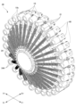
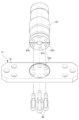
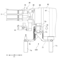
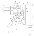
- FIG. 1 is a perspective view showing a tool exchange device according to an embodiment of the present invention.
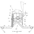
- FIG. 13 is a view of the tool changer as viewed in the Y+ direction.
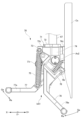
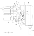
- FIG. 13 is a view of the arm and its surroundings viewed in the Y+ direction.
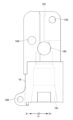
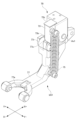
- FIG. 13 is a side view of the fixing member as viewed in the X+ direction.
- 11 is a cross-sectional view of the magazine as viewed in the Y+ direction.
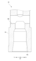
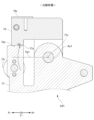
- FIG. 8 is a cross-sectional view of the pot body as viewed in the X-direction, specifically, a cross-section taken along line fig. 8-fig. 8 in FIG. 7.
- FIG. 1 is a cross-sectional view of a pot body with a clamp mechanism attached thereto, as viewed in the X-direction.
- 11 is a cross-sectional view taken in the X-direction, showing a state in which a position maintaining member is further attached to the pot body.
- FIG. 1 is a cross-sectional view of a tool pot holding a tool as viewed in the X-direction.
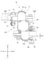
- FIG. 13 is a view of the pot body viewed in the Y+ direction.
- 4 is a cross-sectional view of the arm rotating device as viewed in the Y+ direction.
- FIG. FIG. 4 is an exploded perspective view showing a pivot member and an arm base.
- FIG. 11 is a cross-sectional view of the lower part of the pivot member and the arm base as viewed in the Y+ direction.
- FIG. FIG. 13 is a view of the arm as viewed in the Y+ direction.
- FIG. 13 is a view showing the arm and the spindle-side cam Cs as viewed in the Y+ direction.
- 1 is a perspective view showing a first gripping member 77 and its surroundings.
- FIG. 13 is a view of the first gripping member 77 and its surroundings as viewed in the Y+ direction.
- 22 is a cross-sectional view of the first gripping member 77 and the first base member as viewed in the Y+ direction, specifically, a cross-section taken along line fig22-fig22 in FIG. 18.
- FIG. 13 is a cross-sectional view of a first gripping member 77 and a first base member in a comparative example, viewed in the Y+ direction.
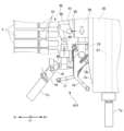
- FIG. 4 is a diagram showing an initial state of tool replacement by the tool replacement device.
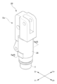
- FIG. FIG. FIG. FIG. FIG. FIG. FIG. FIG. FIG. FIG. 11 is a perspective view showing a tool pot according to a second embodiment.
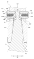
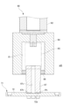
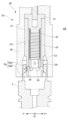
- 35 is a cross-sectional view of the tool pot as viewed in the X-direction, specifically, a cross-section taken along line fig. 35-fig. 35 shown in FIG. 34.
- 11 is a cross-sectional view taken in the X-direction, showing a state in which a tool is being held in the tool pot.
- FIG. 1 is a cross-sectional view of a tool pot holding a tool as viewed in the X-direction.
- FIG. 38 is a cross-sectional view of the tool pot seen from below, specifically, a cross-section taken along line fig 38-fig 38 shown in FIG. 37.
- FIG. 11 is a perspective view showing another example of a bridge.
- the first embodiment is a reference form of the present disclosure
- the second embodiment is an embodiment of the present disclosure.
- Tool changer 80 shown in Fig. 1 is installed relative to machine tool 90 as shown in Fig. 2.
- X direction two predetermined directions that are perpendicular to each other in a horizontal plane as shown in Fig. 1
- Y direction two predetermined directions that are perpendicular to each other in a horizontal plane as shown in Fig. 1
- X- direction two predetermined directions that are perpendicular to each other in a horizontal plane as shown in Fig. 1
- the opposite direction will be referred to as the "X+ direction”.
- Y- direction the opposite direction
- Y+ direction the opposite direction
- the machine tool 90 includes a spindle assembly 95.
- the spindle assembly 95 has a spindle 97 and a housing 96.
- the spindle 97 is installed with its axial length oriented in the vertical direction.
- the housing 96 covers the spindle 97.
- the spindle assembly 95 is configured to be capable of being raised and lowered.
- the base end of one of the multiple tools T is attached to the lower end of the spindle 97.
- a pull stud bolt pB is provided at the base end of each tool T.
- the tool T of the multiple tools T that has been attached to the spindle 97 so far will be referred to as the "previously used tool Tp”
- the tool T of the multiple tools T that will be next attached to the spindle 97 will be referred to as the "next used tool Tn.”
- the tool changer 80 includes a control device 51, and also includes a magazine 30, a magazine rotation device 39, an arm 70, an arm rotation device 60, an arm lifting device 55, and a pot drive mechanism 40 within the internal space wS of the machine tool 90.
- the "magazine 30" may be read as the "tool magazine”
- the arm 70 may be read as the "tool changer arm”.
- the magazine 30 and the spindle assembly 95 are arranged side by side in the X direction, and specifically, the spindle assembly 95 is arranged on the +X direction side of the magazine 30.
- the arm rotation device 60 is provided between the magazine 30 and the spindle assembly 95.
- the pot drive mechanism 40 is provided between the magazine 30 and the arm rotation device 60.
- the arm 70 is provided below the arm rotation device 60.
- the arm lifting device 55 is provided above the arm rotation device 60.
- the magazine 30 shown in FIG. 1 includes a magazine base 38, a rotating member 35, and a plurality of tool pots 10.
- the rotating member 35 is attached to the magazine base 38 so as to be rotatable about an axis in the X direction.
- the magazine rotation device 39 is attached to the magazine base 38.
- the magazine rotation device 39 includes an actuator such as a motor.
- the magazine rotation device 39 rotates the rotating member 35 about an axis in the X direction relative to the magazine base 38.
- the multiple tool pots 10 are attached to the rotating member 35 in a line in the direction of rotation. As a result, by rotating the rotating member 35, one of the multiple tool pots 10 is placed in the lowest "exchange position ep" which serves as a standby position for tool exchange.
- the tool pot 10 at the exchange position ep rotates around the axis in the Y direction to an exchange angle Ea shown in FIG. 26 and a storage angle Sa shown in FIG. 24.
- the exchange angle Ea shown in FIG. 26 is the angle at which the held tool T can be exchanged, and more specifically, the angle at which the tool pot 10 stands upright in the vertical direction.
- the storage angle Sa shown in FIG. 24 is the angle at which the held tool T is stored, and more specifically, the angle at which the tool pot 10 lies down in the X direction.
- the magazine 30 further includes a plurality of biasing members 31 and a fixed member 34.
- Each biasing member 31 is provided for each tool pot 10.
- the fixed member 34 is a metal member fixed to the swivel member 35.
- the fixed member 34 extends in an annular shape in the swivel direction of the swivel member 35.
- the fixed member 34 has support portions 344 arranged in the swivel direction of the swivel member 35.
- the support portions 344 are provided for each tool pot 10.
- each support portion 344 is key-shaped so as to be able to engage with the end of the biasing member 31.
- each biasing member 31 biases the corresponding tool pot 10 toward the storage angle Sa.
- each tool pot 10 includes a pot body 18, a clamping mechanism 12, and a posture maintaining member 13.
- Each pot body 18 is made of resin. As shown in FIG. 1, each pot body 18 is attached to the rotating member 35 so as to be rotatable about an axis Ax that extends in a tangential direction to the rotating direction of the rotating member 35. Therefore, the tool pot 10 at the exchange position ep shown in FIG. 3 can rotate about an axis in the Y direction.
- the upper part of the pot body 18 is provided with a recess 181 for mounting the pot roller 48 described later. Furthermore, as shown in FIG. 12, the pot body 18 is provided with a roller hole 182, an axle hole 184, and an engagement hole 188.
- the roller hole 182 is a hole for mounting a shaft material that rotatably supports the pot roller 48 described later.
- the axle hole 184 is a hole for mounting the aforementioned shaft material Ax. As described above, one end of the urging member 31 is inserted into the engagement hole 188.
- the tool pot 10 is configured as follows when viewed at the exchange angle Ea in the exchange position ep shown in Figure 2.
- the pot body 18 has an insertion hole 18v extending upward from the bottom end of the pot body 18, into which the pull stud bolt pB of the tool T can be inserted. Therefore, the pot body 18 is cylindrical and opens downward. As shown in FIG. 8, the upper part of the pot body 18 has a clamp attachment hole 18h extending in the Y direction and intersecting with the insertion hole 18v.
- the clamp mechanism 12 includes a clamp base 122, a pair of contact members 127, and a pair of biasing members 126.
- the clamp base 122 is a metal member.
- Each biasing member 126 is a metal compression spring.
- Each contact member 127 is a metal ball.
- the clamp mechanism 12 is made of metal.
- the clamp base 122 extends in the Y direction, and a cylindrical hole 122h extending in the Y direction is provided on the inside of the clamp base 122.
- the clamp base 122 is cylindrical.
- a clamp hole 122v is provided in the center of the clamp base 122 in the Y direction, which passes through the clamp base 122 in the vertical direction and intersects with the cylindrical hole 122h.
- a head 122e is formed on the end of the clamp base 122 on the Y+ direction side, protruding radially outward from the clamp base 122 further than other parts.
- the clamp base 122 is attached to the pot body 18 by inserting the clamp base 122 into the clamp mounting hole 18h in the Y+ direction.
- a pair of contact members 127 are installed inside the cylindrical hole 122h. Specifically, the Y- side contact member 127 is installed on the Y- side of the axis of the clamp hole 122v so that it can be displaced in the Y direction. On the other hand, the Y+ side contact member 127 is installed on the Y+ side of the axis of the clamp hole 122v so that it can be displaced in the Y direction.
- the pair of biasing members 126 are installed in the cylindrical hole 122h at a position located outside the pair of contact members 127 in the Y direction.
- Retainers 125 are attached to both ends of the clamp base 122 in the Y direction to hold the outer ends of the pair of biasing members 126 in the Y direction.
- each biasing member 126 is interposed between the retainer 125 and the contact member 127, and biases the contact member 127 inward in the Y direction.
- the biasing member 126 on the Y- side biases the contact member 127 on the Y- side in the Y+ direction
- the biasing member 126 on the Y+ side biases the contact member 127 on the Y+ side in the Y- direction.
- the clamp base 122 has an engagement recess 122d that is recessed upward in the area including the lower end of the clamp hole 122v and its surrounding area.
- the posture-maintaining member 13 shown in FIG. 7 is a metal member that is inserted into the insertion hole 18v of the pot body 18.
- An insertion hole 13v is formed in the posture-maintaining member 13.
- a protrusion 131 that protrudes upward is formed in the inner peripheral portion of the posture-maintaining member 13, i.e., the portion on the insertion hole 13v side.
- the projection 131 of the attitude-maintaining member 13 is engaged with the engagement recess 122d of the clamp base 122 by press-fitting or the like.
- the insertion hole 13v of the attitude-maintaining member 13 is a hole for passing the pull stud bolt pB to the clamp mechanism 12 when the pull stud bolt pB is inserted into the insertion hole 18v of the pot body 18.
- the insertion hole 13v has a tapered shape that reduces in diameter as it advances upward, i.e., toward the clamp mechanism 12. This allows the insertion hole 13v to guide the pull stud bolt pB into the clamp hole 122v of the clamp mechanism 12.
- the pair of contact members 127 When the pull stud bolt pB is inserted into the clamp hole 122v shown in FIG. 10, the pair of contact members 127 are pushed outward in the Y direction by the pull stud bolt pB, and then, as shown in FIG. 11, the pair of contact members 127 return to the inside in the Y direction. As a result, the pair of contact members 127 hold the pull stud bolt pB from the outside in the Y direction.
- the arm lifting device 55 includes an actuator such as a motor.
- the arm lifting device 55 raises and lowers the arm rotation device 60 to which the arm 70 is attached, thereby raising and lowering the arm rotation device 60 and the arm 70.
- the uppermost point in the driving range of the arm 70 by the arm lifting device 55 will be referred to as the "uppermost point of the arm,” and the lowermost point in that driving range will be referred to as the "lowest point of the arm.”
- the pot drive mechanism 40 shown in Figure 2 includes a pot drive cam 41, a link roller 45, a link mechanism 46, and a pot roller 48.
- the pot drive cam 41 is attached to the arm rotation device 60 and moves up and down together with the arm rotation device 60 and the arm 70.
- the link roller 45 is attached to the upper end of the link mechanism 46.
- the pot roller 48 is attached to the lower part of the end of the pot body 18 on the X+ direction side so as to be rotatable about an axis in the Y direction.
- the link roller 45 is biased against the pot drive cam 41 by the weight of the link mechanism 46 and the biasing force of the biasing member 31.
- the arm rotation device 60 shown in FIG. 2 includes a driving source 62, a housing 64, a reducer 65, a seal member 66, and a pivot member 67.
- the driving source 62 is an actuator such as a motor.
- the housing 64 has a cylindrical shape that opens at the top and bottom. An internal space iS is formed inside the housing 64.
- the reducer 65 is stored in the internal space iS.
- the upper opening of the housing 64 is closed by the driving source 62.
- the pivot member 67 is provided below the reducer 65.
- the driving source 62 rotates the pivot member 67 via the reducer 65.
- the seal member 66 closes the lower opening of the housing 64 while allowing the pivot member 67 to pass in the vertical direction.
- a base plate 72, which is part of an arm base 71, which is part of an arm 70, is fixed to the lower end of the pivot member 67. As a result, the arm 70 rotates around the vertical axis together with the pivot member 67.
- a through hole 67v is provided in the pivot shaft member 67, and a communication passage Ph is formed between the pivot shaft member 67 and the base plate 72.
- the through hole 67v and the communication passage Ph allow the internal space iS to communicate with the outside of the housing 64.
- the through hole 67v penetrates the pivot shaft member 67 in the vertical direction. Therefore, the upper end of the through hole 67v is connected to the internal space iS.
- a communication groove 67h is provided on the lower surface of the pivot shaft member 67, extending from the lower end of the through hole 67v to the outer circumferential surface of the pivot shaft member 67. Note that in this embodiment, there are two communication grooves 67h, but there may be one, or three or more.
- the upper surface of the base plate 72 is provided with an engagement recess 72d.
- the lower end of the pivot shaft member 67 engages with the engagement recess 72d.
- the base plate 72 is fixed to the lower end of the pivot shaft member 67 by a bolt Bt or the like.
- a communication passage Ph is formed inside the inner wall of the communication groove 67h.
- the vertical depth of the engagement recess 72d is deeper than the vertical depth of the communication groove 67h.
- an upward extension portion 67e is formed, which extends upward from the ceiling surface of the end of the communication groove 67h on the outer periphery side of the pivot shaft member 67 and opens to the outside.
- the inside of the inner wall of this upward extension portion 67e is also part of the communication passage Ph.
- the communication passage Ph includes the inside of the inner wall of the communication groove 67h and the inside of the inner wall of the upward extension portion 67e.
- the ceiling surface of the communication groove 67h i.e., the ceiling surface of the communication passage Ph other than the upward extension portion 67e, is located lower than the lower end Lp of the opening of the communication passage Ph on the outer peripheral surface side of the rotating shaft member 67, i.e., the upper surface of the base plate 72.
- the gas in the through hole 67v is sucked in, but by ensuring that the length of the through hole 67v is sufficient, the cutting fluid cf that has accumulated in the communication passage Ph can only rise to the middle of the through hole 67v.
- the arm 70 shown in FIG. 2 includes an arm base 71, a first gripping member 77, a second gripping member 78, a first biasing member 75, and a second biasing member 76.
- the arm base 71 includes a first base member 73 and a second base member 74.
- the state in which the arm 70 is at a predetermined rotation angle is referred to as the "first basic state bS1," and as shown in FIG. 29, the state in which the arm 70 is rotated 180° around the vertical axis from the first basic state bS1 is referred to as the "second basic state bS2.”
- the arm 70 is configured as follows.
- the first base member 73 is attached to the underside of the portion of the base plate 72 on the Y+ direction side.
- the second base member 74 is attached to the underside of the portion of the base plate 72 on the Y- direction side.
- the first gripping member 77 has a broken line shape that extends downward and then in the X- direction.
- the second gripping member 78 has a broken line shape that extends downward and then in the X+ direction.
- the upper end of the first gripping member 77 is attached to the first base member 73 by a first shaft member Ax1 extending in the Y direction so as to be rotatable about an axis in the Y direction.
- the upper end of the second gripping member 78 is attached to the second base member 74 by a second shaft member Ax2 extending in the Y direction so as to be rotatable about an axis in the Y direction. In this way, the first gripping member 77 and the second gripping member 78 are attached to the arm base 71.
- a first gripping portion 77e is provided at the tip of the first gripping member 77.
- a second gripping portion 78e is provided at the tip of the second gripping member 78.
- the first gripping member 77 and the second gripping member 78 will be collectively referred to as “gripping members 77, 78.”
- the first gripping portion 77e and the second gripping portion 78e will be collectively referred to as “gripping portions 77e, 78e.”
- Each gripping portion 77e, 78e has a U-shape that opens toward the tip, and is configured to be able to grip the portion of the upper part of the tool T below the pull stud bolt pB.
- each of the gripping members 77, 78 is displaced between a gripping angle Ga for gripping the tool T and a release angle Ra for releasing the grip of the tool T by rotating about an axis in the Y direction.
- the first biasing member 75 and the second biasing member 76 are both tension springs.
- the first biasing member 75 has one end attached to the first gripping member 77 and the other end attached to the first base member 73.
- the second biasing member 76 has one end attached to the second gripping member 78 and the other end attached to the second base member 74.
- the first biasing member 75 biases the first gripping member 77 toward the gripping angle Ga.
- the second biasing member 76 biases the second gripping member 78 toward the gripping angle Ga.
- a first roller 77r is attached to the first gripping member 77.
- a second roller 78r is attached to the second gripping member 78.
- a magazine side cam Cm is provided on the X- direction side of the arm 70.
- the magazine side cam Cm is attached to the frame or housing of the tool changer 80.
- a spindle side cam Cs is provided on the X+ direction side of the arm 70.
- the spindle side cam Cs is attached to the frame or housing 96 of the spindle assembly 95, and rises and falls together with the spindle assembly 95. Note that the "spindle side cam Cs" may be read as a "pressure member".
- the underside of the end of the first base member 73 on the X-direction side forms a first abutment surface 73s.
- the first abutment surface 73s abuts against the first gripping member 77 at a position that prevents rotation toward the gripping angle Ga, thereby limiting the range of rotation of the first gripping member 77 toward the gripping angle Ga.
- a first abutment surface 77s that abuts parallel to the first abutment surface 73s from below is provided on the upper part of the first gripping member 77.
- the underside of the end portion on the X+ direction side of the second base member 74 constitutes a second abutment surface 74s.
- the second abutment surface 74s abuts against the second gripping member 78 at a position that prevents rotation toward the gripping angle Ga, thereby limiting the range of rotation of the second gripping member 78 toward the gripping angle Ga.
- a second abutment surface 78s that abuts parallel to the second abutment surface 74s from below is provided on the upper portion of the second gripping member 78.
- the above explanation is for the arm 70 when viewed in the first basic state bS1.
- the explanation for the arm 70 when viewed in the second basic state bS2 is similar to the above explanation, except that "first" and "second" are read as the other, and the reference numerals are read as appropriate.
- the first gripping member 77 shown in FIG. 22 repeatedly collides with the first abutment surface 73s by repeatedly rotating toward the gripping angle Ga side and toward the release angle Ra side. If the first gripping member 77 slides against the first abutment surface 73s during this collision, wear will progress on the first abutment surface 73s and the first gripping member 77, which may cause malfunction of the arm 70. Similarly, if the second gripping member 78 slides against the second abutment surface 74s, wear will progress on the second abutment surface 74s and the second gripping member 78, which may cause malfunction of the arm 70.
- the first abutment surface 73s extends along a first imaginary plane Vp1 that includes the entire rotation axis 77c of the first gripping member 77, i.e., the entire center line of the first shaft material Ax1.
- the tangent direction of the rotation direction of the first gripping member 77 on the first abutment surface 73s necessarily faces the direction perpendicular to the surface of the first abutment surface 73s. This suppresses the generation of a force that would cause the first gripping member 77 to shift parallel to the first abutment surface 73s.
- the tangent direction of the rotation direction of the first gripping member 77 at the first abutment surface 73s is inclined with respect to the perpendicular direction of the first abutment surface 73s. This makes it easier for a force to be applied that causes the first gripping member 77 to shift parallel to the first abutment surface 73s.
- this embodiment makes it possible to reduce sliding when the first gripping member 77 collides with the first abutment surface 73s.
- the second abutment surface 74s extends along the second imaginary plane Vp2 that includes the entire rotation axis 78c of the second gripping member 78, i.e., the entire center line of the second shaft material Ax2. Therefore, for the same reason as in the case of the first abutment surface 73s, sliding can be suppressed when the second gripping member 78 collides with the second abutment surface 74s.
- the second problem to be solved by the arm 70 of this embodiment will be described.
- the power to the arm rotation device 60 is usually also turned off.
- the arm 70 is released from the current rotation phase that was held by the arm rotation device 60.
- the spindle side cam Cs is pressing against the second gripping member 78 or when the spindle side cam Cs is pressing against the first gripping member 77, if the power to the arm rotation device 60 is turned off, the arm 70 will rotate due to the pressing force.
- the arm 70 is configured as follows.
- a plate-shaped first rotation stop member 73z that protrudes from the first base member 73 in the Y+ direction is provided on the X- direction side of the upper surface of the first base member 73.
- a plate-shaped second rotation stop member 74z that protrudes from the second base member 74 in the Y- direction is provided on the X+ direction side of the upper surface of the second base member 74.
- the first rotation stop member 73z and the second rotation stop member 74z are collectively referred to as "rotation stop members 73z, 74z.”
- the second rotation stop member 74z is disposed to the side of the spindle side cam Cs in the Y+ direction with a small clearance CLh as shown in FIG. 18. This second rotation stop member 74z restricts the rotation of the arm 70 when the power supply to the arm rotation device 60 is turned OFF.
- the above explanation is for the arm 70 when viewed in the first basic state bS1.
- the explanation for the arm 70 when viewed in the second basic state bS2 is similar to the above explanation, except that "first" and "second" are read as the other, and the reference numerals are read as appropriate.
- control device 51 controls each drive device, including the magazine rotation device 39, the arm rotation device 60, and the arm lifting device 55.
- the specific procedure for tool replacement based on the control by the control device 51 will be described below.
- the arm 70 in the initial state, the arm 70 is at the uppermost point. At this time, the arm 70 may be in either the first basic state bS1 or the second basic state bS2. Below, a case where the arm 70 is in the first basic state bS1 in the initial state will be described.
- the tool pot 10 at the replacement position ep is positioned at a storage angle Sa according to the profile of the pot drive cam 41.
- the first gripping member 77 is positioned at a release angle Ra according to the profile of the magazine-side cam Cm, and the second gripping member 78 is also positioned at a release angle Ra according to the profile of the spindle-side cam Cs.
- the first gripping member 77 rotates to a gripping angle Ga according to the profile of the magazine side cam Cm, and grips the next tool to be used Tn in the tool pot 10 at an exchange angle Ea. From that state, as shown in FIG. 27, the first gripping member 77 descends to remove the next tool to be used Tn from the tool pot 10.
- the arm 70 is rotated 180° around the vertical axis by the arm rotation device 60.
- This rotation changes the state from the first basic state bS1 to the second basic state bS2.
- the second gripping member 78 and the previously used tool Tp are on the X- side
- the first gripping member 77 and the next tool to be used Tn are on the X+ side.
- the second gripping member 78 rises as shown in FIG. 31 to attach the previously used tool Tp to the tool pot 10 at the exchange angle Ea. From that state, as shown in FIG. 32, the second gripping member 78 rotates toward the release angle Ra in accordance with the profile of the magazine-side cam Cm, and releases its grip on the previously used tool Tp.
- the above describes the case where the initial state is the first basic state bS1.
- the explanation for the case where the initial state is the second basic state bS2 is similar to the above explanation, except that "first" and "second” are read as the other, and the symbols are read as the corresponding ones.
- the fixed member 34 is fixed to the swivel member 35 and extends in the swivel direction.
- the fixed member 34 has support parts 344 arranged in the swivel direction for each tool pot 10.
- a biasing member 31 is provided for each tool pot 10.
- Each biasing member 31 is attached to the corresponding tool pot 10 and the corresponding support part 344, and biases the corresponding tool pot toward the storage angle Sa. Therefore, a single fixed member 34 can support multiple biasing members 31 on the swivel member 35. Therefore, multiple biasing members 31 can be supported on the swivel member 35 without providing a support member for supporting the biasing member 31 on the magazine base 38 for each tool pot 10. This reduces the assembly man-hours for the tool magazine 30 and the manufacturing cost.
- the biasing member 31 is a tension spring.
- Each support portion 344 has a key shape that can engage with the end of the biasing member 31. This allows the fixing member 34 to be realized with a simple shape.
- the fixing member 34 is annular and goes around in the rotation direction of the rotating member 35. Therefore, the strength of the fixing member 34 can be ensured more efficiently than when the fixing member 34 is C-shaped, for example.
- the clamp mechanism 12 is attached to the clamp attachment hole 18h.
- the posture-maintaining member 13 is inserted into the insertion hole 18v and maintains the posture of the clamp mechanism 12 relative to the pot body 18. Therefore, the posture of the clamp mechanism 12 relative to the pot body 18 can be maintained without using screws or the like. This makes it possible to select a material for the pot body 18 that is difficult to secure with screws in terms of strength, and to simplify the structure of the pot body 18. This leads to a reduction in weight, size, and cost of the tool pot 10.
- the posture-maintaining member 13 is formed with an insertion hole 13v that allows the pull stud bolt pB to pass through to the clamp mechanism 12 when the pull stud bolt pB is inserted into the insertion hole 18v. Therefore, the posture-maintaining member 13 does not impede the passage of the pull stud bolt pB, and the outer shape of the posture-maintaining member 13 is necessarily larger than the outer shape of the pull stud bolt pB. This allows the size of the posture-maintaining member 13 to be sufficiently large within a limited space such as the inside of the pot body 18. This allows the posture of the clamp mechanism 12 relative to the pot body 18 to be sufficiently firmly maintained.
- the tool pot 10 can be made lighter, smaller, and less expensive, while still maintaining a sufficiently strong position of the clamp mechanism 12 relative to the pot body 18.
- a protrusion 131 that protrudes toward the clamp mechanism 12 is formed on the portion of the posture maintaining member 13 on the side of the insertion hole 13v. As shown in Figure 10, the protrusion 131 engages with the clamp mechanism 12, thereby maintaining the posture of the clamp mechanism 12 relative to the pot body 18. This allows the posture of the clamp mechanism 12 to be maintained with a simple shape.
- the insertion hole 13v has a tapered shape that narrows toward the clamp mechanism 12. Therefore, the insertion hole 13v can guide the pull stud bolt pB into the clamp mechanism 12.
- the pot body 18 shown in FIG. 10 is made of resin. This allows the tool pot 10 to be made lighter, smaller, and less expensive.
- the clamp mechanism 12 and the posture-maintaining member 13 are made of metal. This ensures that the clamp mechanism 12, which actually holds the tool, and the posture-maintaining member 13, which maintains its posture, have sufficient strength.
- the posture-maintaining member 13 maintains the posture of the clamp mechanism 12 relative to the pot body 18 by engaging with the clamp base 122, which houses a pair of contact members 127 and a pair of biasing members 126 inside. This allows the posture of the clamp mechanism 12 to be maintained in a simple manner.
- the pivot shaft member 67 is provided with a through hole 67v that extends vertically and whose upper end communicates with the internal space iS.
- a base plate 72 is attached to the lower end of the pivot shaft member 67.
- a communication passage Ph is formed between the pivot shaft member 67 and the base plate 72, connecting the lower end of the through hole 67v to the outside of the outer circumferential surface of the pivot shaft member 67. Therefore, even if cutting fluid enters and accumulates in the internal space iS, the cutting fluid can be discharged through the through hole 67v and the communication passage Ph to the in-machine space wS.
- the ceiling surface of the communication groove 67h i.e., the ceiling surface of the communication passage Ph other than the upward extension portion 67e, is located at a lower position than the lower end Lp of the opening of the communication passage Ph on the outer peripheral surface side of the rotating shaft member 67.
- the first gripping member 77 has a first contact surface 77s that contacts the first abutment surface 73s in parallel. Therefore, compared to when, for example, a roller or the like of the first gripping member 77 makes linear contact with the first abutment surface 73s, the contact area of the first gripping member 77 with the first abutment surface 73s can be increased, thereby reducing wear between the first abutment surface 73s and the first gripping member 77.
- the second gripping member 78 has a second contact surface 78s that contacts the second abutment surface 74s in parallel. Therefore, for the same reason as above, wear between the second abutment surface 74s and the second gripping member 78 can be reduced.
- the arm 70 is provided with a first rotation stop member 73z and a second rotation stop member 74z.
- the second rotation stop member 74z stops the rotation by abutting against the spindle side cam Cs at a position that prevents the rotation due to the pressure.
- the first rotation stop member 73z stops the rotation by abutting against the spindle side cam Cs at a position that prevents the rotation due to the pressure.
- the first rotation stop member 73z or the second rotation stop member 74z can prevent the arm 70 from rotating due to the pressure.
- This embodiment differs from the first embodiment in that the magazine 30 shown in FIG. 4 includes a plurality of tool pots 20 shown in FIG. 34 instead of a plurality of tool pots 10. Note that the pot rollers are not shown in FIG. 34. Also, as shown in FIG. 36, this embodiment differs in that an engagement portion Eg is formed at the base end of each tool T instead of a pull stud bolt pB.
- the engagement portion Eg has an upper portion EgU and a lower portion EgD. The upper portion EgU protrudes more toward the inner circumference of the tool T than the lower portion EgD. Note that the engagement portion Eg may be read as the "end of the tool.”
- the tool pot 20 includes a pot body 28, a cylindrical member 27, a biasing member 22, a piece 23, and a number of contact members 24.
- the pot body 28 is made of resin.
- the cylindrical member 27 is made of metal.
- the biasing member 22 is a metal compression spring.
- the piece 23 is made of metal.
- Each contact member 24 is a metal ball.
- the tool pot 20 is configured as follows when viewed in the state shown in FIG. 35, i.e., when the tool pot 20 is positioned at the exchange angle Ea in the exchange position ep.
- the pot body 28 has a cylindrical shape that opens downward, and is configured so that the engagement portion Eg of the tool T can be inserted from below, as shown in Figures 36 and 37. Therefore, “upward” in the following may be read as “the direction in which the tool T is inserted,” and “downward” in the following may be read as "the direction opposite to the insertion of the tool T.”
- the cylindrical member 27 is fixed inside the pot body 28 with its axis oriented vertically.
- the piece 23 is installed inside the lower end of the cylindrical member 27 so that it can be displaced vertically.
- the space inside the cylindrical member 27 above the piece 23 is referred to as the "storage space sS.”
- the biasing member 22 is stored in the storage space sS.
- a retainer 21 for holding the upper end of the biasing member 22 is attached to the upper end of the cylindrical member 27.
- the biasing member 22 is interposed between the retainer 21 and the piece 23, and biases the piece 23 downward.
- a number of mounting holes 27h are provided through the lower end of the cylindrical member 27. In the bottom view shown in FIG. 38, these mounting holes 27h extend radially in the radial direction of the cylindrical member 27.
- Each contact member 24 is attached to one of the mounting holes 27h. As a result, each contact member 24 is configured to be able to protrude outward from the outer periphery of the cylindrical member 27 and retract inward. Note that although the figure shows three contact members 24, the number may be two or less, or four or more.
- the piece 23 has a tapered surface 23t at its lower end.
- the tapered surface 23t presses the multiple contact members 24, causing them to protrude outward from the outer periphery of the lower end of the tubular member 27.
- a communication passage Pv is formed in the bridge 23.
- the communication passage Pv is configured as follows:
- the communication passage Pv extends from the upper end to the lower end of the piece 23, connecting the storage space sS with the outside.
- a communication hole 23v is formed as the communication passage Pv, as shown in FIG. 39.
- the communication hole 23v penetrates the piece 23 in the vertical direction.
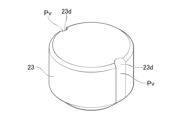
- a communication groove 23d may be formed as the communication passage Pv, as shown in FIG. 40.
- the communication groove 23d is recessed into the outer circumferential surface of the piece 23 and extends in the vertical direction. Note that the above explanation is for the case where the tool pot 20 is arranged at the exchange angle Ea in the exchange position ep, as described above.
- the coolant if coolant or the like infiltrates from the internal space wS shown in FIG. 35 into the storage space sS, the coolant is discharged from the communication passage Pv.
- the embodiment described above can be modified, for example, as follows.
- the arm 70 shown in Fig. 16 may have three or more gripping members 77, 78 instead of two.
- the arm rotation device 60 shown in Fig. 2 may rotate the arm 70 by 120° instead of 180°.
- a tool magazine (30) includes a plurality of tool pots (20), each of which holds a tool (T) of a machine tool (90), the tool pots (20), A pot body (28) configured so that an end portion of the tool (T) can be inserted therein; a cylindrical member (27) fixed inside the pot body (28) with its axial direction facing the insertion direction of the tool (T); a piece (23) disposed inside the cylindrical member (27) so as to be displaceable in the insertion direction and in a counter-insertion direction opposite thereto; a biasing member (22) that is stored in a storage space (sS) that is a space on the insertion direction side of the piece (23) inside the cylindrical member (27) and biases the piece (23) in the counter-insertion direction; a contact member (24) that protrudes outward from an outer periphery of the cylindrical member (27) as the piece (23) is displaced in the counter-insertion direction, When an end of the tool (T) is inserted into the tool (T) pot (10), the end
- the piece (23) has a communication hole (23v) formed therein as the communication passage (Pv) penetrating the piece (23) in the insertion direction.
- a communication groove (23d) extending in the insertion direction is formed on the outer periphery of the piece (23) as the communication passage (Pv). 3.
Landscapes
- Engineering & Computer Science (AREA)
- Mechanical Engineering (AREA)
- Automatic Tool Replacement In Machine Tools (AREA)
Abstract
たとえ格納空間内にクーラント液が浸入しても当該クーラント液が格納空間内から排出され易い工具ポットを、提供することを目的とする。工具ポットは、ポット本体と筒状部材と駒と付勢部材と接触部材とを備える。筒状部材は、ポット本体の内側に、軸線方向を工具の挿入方向に向けて固定されている。駒は、筒状部材の内側に設置されている。付勢部材は、筒状部材の内側における駒よりも挿入方向側の格納空間に格納されており、駒を反挿入方向に向けて付勢する。接触部材は、駒の反挿入方向への変位に伴い筒状部材の外周部から外方に向けて突出する。工具の端部が工具ポットに挿入された際には、当該工具の端部が接触部材によって保持される。駒における挿入方向側の端部から駒における反挿入方向側の端部にまで延在して、格納空間とその外部とを連通させる連通路が形成されている。
Description
本開示は、複数の工具ポットを備え、各工具ポットによって工作機械の工具を保持する工具マガジンにおける当該工具ポットに関する。
工具ポットの中には、ポット本体と、筒状部材と、付勢部材と、駒と、接触部材と、を備えるものがある。ポット本体は、工具の端部を挿入可能に構成されている。筒状部材は、ポット本体の内側に、軸線方向を工具の挿入方向に向けて固定されている。駒は、筒状部材の内側に、挿入方向とその反対方向としての反挿入方向に変位可能に設置されている。
付勢部材は、筒状部材の内側における駒よりも挿入方向側の空間としての格納空間に格納されており、駒を反挿入方向に向けて付勢する。接触部材は、駒の反挿入方向への変位に伴い筒状部材の外周部から外方に向けて突出する。工具の端部が工具ポットに挿入された際には、当該工具の端部が接触部材によって保持される。
上記の工具ポットにおいて、工具の保持およびその解除を行う際、付勢部材が伸び縮みする。これにより、格納空間は、膨張および圧縮を繰り返す。ところで、工具ポットが設置される空間には、工具による加工時に使用するクーラント液が霧散している可能性がある。そのため、格納空間の膨張および圧縮の繰り返しにより、格納空間内にクーラント液が浸入する可能性がある。格納空間は筒状部材と駒で囲まれているため、浸入したクーラント液の一部は、格納空間内に残りやすい。そのことから、格納空間内にクーラント液が長期間残り続け、筒状部材や付勢部材や駒の腐食が進行してしまうおそれがある。その腐食が、工具ポットによる工具の保持動作についての不良原因に繋がるおそれがある。
本開示は、上記事情に鑑みてなされたものであり、たとえ格納空間内にクーラント液が浸入しても当該クーラント液が格納空間内から排出され易い工具ポットを、提供することを目的とする。
本開示は、
複数の工具ポットを備え、各前記工具ポットによって工作機械の工具を保持する工具マガジンにおける当該工具ポットであって、
前記工具の端部を挿入可能に構成されているポット本体と、
前記ポット本体の内側に、軸線方向を前記工具の挿入方向に向けて固定されている筒状部材と、
前記筒状部材の内側に、前記挿入方向とその反対方向としての反挿入方向に変位可能に設置されている駒と、
前記筒状部材の内側における前記駒よりも前記挿入方向側の空間としての格納空間に格納されており、前記駒を前記反挿入方向に向けて付勢する付勢部材と、
前記駒の前記反挿入方向への変位に伴い前記筒状部材の外周部から外方に向けて突出する接触部材と、を備え、
前記工具の端部が前記工具ポットに挿入された際には、当該工具の端部が前記接触部材によって保持され、
前記駒における前記挿入方向側の端部から前記駒における前記反挿入方向側の端部にまで延在して、前記格納空間とその外部とを連通させる連通路が形成されている。
複数の工具ポットを備え、各前記工具ポットによって工作機械の工具を保持する工具マガジンにおける当該工具ポットであって、
前記工具の端部を挿入可能に構成されているポット本体と、
前記ポット本体の内側に、軸線方向を前記工具の挿入方向に向けて固定されている筒状部材と、
前記筒状部材の内側に、前記挿入方向とその反対方向としての反挿入方向に変位可能に設置されている駒と、
前記筒状部材の内側における前記駒よりも前記挿入方向側の空間としての格納空間に格納されており、前記駒を前記反挿入方向に向けて付勢する付勢部材と、
前記駒の前記反挿入方向への変位に伴い前記筒状部材の外周部から外方に向けて突出する接触部材と、を備え、
前記工具の端部が前記工具ポットに挿入された際には、当該工具の端部が前記接触部材によって保持され、
前記駒における前記挿入方向側の端部から前記駒における前記反挿入方向側の端部にまで延在して、前記格納空間とその外部とを連通させる連通路が形成されている。
以下、本開示の実施形態について、図面を参照しつつ説明する。ただし、本開示は、以下の実施形態に何ら限定されるものではなく、本開示の趣旨を逸脱しない範囲内で適宜変更して実施できる。第1実施形態は、本開示の参考形態であり、第2実施形態が、本開示の実施形態である。
[第1実施形態]
図1に示す工具交換装置80は、図2に示すように工作機械90に対して設置されている。以下、図1に示すように、水平面内で互いに直交し合う所定の2方向を「X方向」および「Y方向」という。また、X方向の一方を「X-方向」といい、その反対方向を「X+方向」という。また、Y方向の一方を「Y-方向」といい、その反対方向を「Y+方向」という。
図1に示す工具交換装置80は、図2に示すように工作機械90に対して設置されている。以下、図1に示すように、水平面内で互いに直交し合う所定の2方向を「X方向」および「Y方向」という。また、X方向の一方を「X-方向」といい、その反対方向を「X+方向」という。また、Y方向の一方を「Y-方向」といい、その反対方向を「Y+方向」という。
図2に示すように、工作機械90は、主軸アセンブリ95を備える。主軸アセンブリ95は、主軸97と筐体96とを有する。主軸97は、軸長方向を上下方向に向けて設置されている。筐体96は、主軸97を覆っている。主軸アセンブリ95は、昇降可能に構成されている。
主軸97の下端部には、複数の工具Tのうちの1つの基端部が取り付けられる。各工具Tの基端部には、プルスタッドボルトpBが設けられている。以下、複数の工具Tのうちの今まで主軸97に取り付けられた工具Tを「先使用工具Tp」といい、複数の工具Tのうちの次に主軸97に取り付けられる工具Tを「次使用工具Tn」という。
図2に示すように、工具交換装置80は、制御装置51を備えると共に、工作機械90の機内空間wS内に、マガジン30と、マガジン旋回装置39と、アーム70と、アーム旋回装置60と、アーム昇降装置55と、ポット駆動機構40と、を備える。なお、「マガジン30」は、「工具マガジン」と読み替えてもよく、アーム70は「工具交換アーム」と読み替えてもよい。
マガジン30と主軸アセンブリ95とは、X方向に並べて設けられており、具体的には、マガジン30よりもX+方向側に主軸アセンブリ95が設けられている。アーム旋回装置60は、マガジン30と主軸アセンブリ95との間に設けられている。ポット駆動機構40は、マガジン30とアーム旋回装置60との間に設けられている。アーム70は、アーム旋回装置60の下方に設けられている。アーム昇降装置55は、アーム旋回装置60の上方に設けられている。
まず、図1に示すマガジン30について説明する。マガジン30は、マガジンベース38と、旋回部材35と、複数の工具ポット10と、を備える。旋回部材35は、マガジンベース38に対してX方向を軸に旋回可能に取り付けられている。マガジン旋回装置39は、マガジンベース38に取り付けられている。マガジン旋回装置39は、モータなどのアクチュエータを備えている。マガジン旋回装置39は、マガジンベース38に対して旋回部材35を、X方向を軸に旋回させる。
複数の工具ポット10は、旋回部材35に対してその旋回方向に並べて取り付けられている。そのことから、旋回部材35の回動によって、複数の工具ポット10のうちの1つが、最も下側にある工具交換用の待機位置としての「交換位置ep」に配される。
交換位置epの工具ポット10は、Y方向を軸とする回動によって、図26に示す交換角度Eaと、図24に示す収納角度Saとに回動する。図26に示す交換角度Eaは、保持する工具Tを交換可能な角度であって、具体的には、工具ポット10が上下方向に起立する角度である。他方、図24に示す収納角度Saは、保持した工具Tを収納しておく角度であって、具体的には、工具ポット10がX方向に倒伏する角度である。
図4に示すように、マガジン30は、さらに、複数の付勢部材31と、固定部材34と、を備える。各付勢部材31は、工具ポット10毎に設けられている。固定部材34は、旋回部材35に固定された金属製の部材である。固定部材34は、旋回部材35の旋回方向に環状に延在している。固定部材34には、支持部344が旋回部材35の旋回方向に並べて設けられている。それらの支持部344は、工具ポット10毎に設けられている。図5に示すように、各支持部344は、付勢部材31の端部に係合可能な鍵形状である。
図6に示すように、付勢部材31の一端部は、自身に対応する工具ポット10の後述する係合孔188に挿入されることによって、当該ポット本体18に取り付けられている。付勢部材31の他端部は、当該工具ポット10に対応する支持部344に取り付けられている。これによって、図4に示すように、各付勢部材31は、自身に対応する工具ポット10を収納角度Sa側に付勢している。
図7に示すように、各工具ポット10は、ポット本体18と、クランプ機構12、姿勢保持部材13と、を備える。
各ポット本体18は、樹脂製である。図1に示すように、各ポット本体18は、旋回部材35の旋回方向の接線方向に延在する軸材Axを軸に、旋回部材35に対して、回動可能に取り付けられている。そのことから、図3に示す交換位置epの工具ポット10は、Y方向を軸に回動可能である。
図7に示すように、ポット本体18の上部には、後述するポットローラ48を取り付けるための凹部181が設けられている。さらに、ポット本体18には、図12に示すように、ローラ孔182と軸孔184と係合孔188とが設けられている。ローラ孔182は、後述するポットローラ48を回転可能に軸支する軸材を取り付けるための孔である。軸孔184は、前述の軸材Axを取り付けるための孔である。係合孔188には、前述の通り、付勢部材31の一端部が挿入される。
工具ポット10は、図2に示す交換位置epにおいて交換角度Eaに配されている状態で見て、以下のように構成されている。
図7に示すように、ポット本体18には、工具TのプルスタッドボルトpBを挿入可能な被挿入穴18vが、ポット本体18の下端から上方に向けて延在している。そのため、ポット本体18は、下方向けて開口した筒状である。図8に示すように、ポット本体18の上部には、Y方向に延在して被挿入穴18vに交わるクランプ取付穴18hが設けられている。
図9に示すように、クランプ機構12は、クランプ基部122と、一対の接触部材127と、一対の付勢部材126と、を備える。クランプ基部122は、金属製の部材である。各付勢部材126は、金属製の押圧バネである。各接触部材127は、金属製のボールである。以上のことから、クランプ機構12は、金属製である。
図7に示すように、クランプ基部122は、Y方向に延在しており、クランプ基部122の内側には、Y方向に延在する筒孔122hが設けられている。よって、クランプ基部122は、筒状である。このクランプ基部122のY方向中央部には、クランプ基部122を上下方向に貫通して筒孔122hに交わるクランプ穴122vが設けられている。クランプ基部122におけるY+方向側の端部には、他の部分よりもクランプ基部122の径方向外方に突出するヘッド122eが形成されている。
図9に示すように、クランプ基部122が、クランプ取付穴18hにY+方向に挿入されることによって、クランプ基部122がポット本体18に対して取り付けられている。
一対の接触部材127は、筒孔122h内に設置されている。具体的には、Y-側の接触部材127は、クランプ穴122vの軸心よりもY-側において、Y方向に変位可能に設置されている。他方、Y+側の接触部材127は、クランプ穴122vの軸心よりもY+側において、Y方向に変位可能に設置されている。
一対の付勢部材126は、筒孔122h内における一対の接触部材127よりもY方向外側に位置する部位に設置されている。クランプ基部122のY方向の両端部には、それら一対の付勢部材126のY方向外側の端部を保持するためのリテーナ125が取り付けられている。よって、各付勢部材126は、リテーナ125と接触部材127との間に介装されており、接触部材127をY方向内側に付勢する。つまり、Y-側の付勢部材126は、Y-側の接触部材127をY+方向に付勢し、Y+側の付勢部材126は、Y+側の接触部材127をY-方向に付勢する。
クランプ基部122におけるクランプ穴122vの下端部およびその周辺を含む部位には、上方に向けて凹む係合凹部122dが形成されている。
図7に示す姿勢保持部材13は、金属製の部材であって、ポット本体18の被挿入穴18vに挿入されている。姿勢保持部材13には、挿通孔13vが形成されている。姿勢保持部材13における内周側の部位、つまり挿通孔13v側の部位には、上側に突出する突起131が形成されている。
図10に示すように、姿勢保持部材13の突起131は、クランプ基部122の係合凹部122dに、圧入などによって係合している。それによって、ポット本体18に対してクランプ機構12が、クランプ取付穴18hの長さ方向、つまりY方向と、クランプ取付穴18hの周方向と、に位置決めされている。それによって、ポット本体18に対するクランプ機構12の姿勢が保持されている。姿勢保持部材13の挿通孔13vは、プルスタッドボルトpBがポット本体18の被挿入穴18vに挿入された際に、プルスタッドボルトpBをクランプ機構12にまで通過させるための孔である。挿通孔13vは、上側に進むに従い、つまりクランプ機構12側に進むに従い縮径するテーパ形状を有する。これによって、挿通孔13vは、プルスタッドボルトpBをクランプ機構12のクランプ穴122vに案内可能に構成されている。
図10に示すクランプ穴122vにプルスタッドボルトpBが挿入された際には、プルスタッドボルトpBによって一対の接触部材127が一旦Y方向外側に押し出されてから、図11に示すように、それら一対の接触部材127がY方向内側に戻る。それによって、一対の接触部材127が、プルスタッドボルトpBをY方向外側から保持する。
なお、以上の説明は、前述の通り、工具ポット10が図2に示す交換位置epにおいて交換角度Eaに配されている状態で見た場合の説明である。
次に、図2に示すアーム昇降装置55について説明する。アーム昇降装置55は、モータなどのアクチュエータを備える。アーム昇降装置55は、アーム70が取り付けられているアーム旋回装置60を昇降させることによって、アーム旋回装置60およびアーム70を昇降させる。以下、アーム昇降装置55によるアーム70の駆動範囲における最上点を、「アーム最上点」といい、当該駆動範囲における最下点を「アーム最下点」という。
次に図2に示すポット駆動機構40について説明する。図3に示すように、ポット駆動機構40は、ポット駆動カム41と、リンクローラ45と、リンク機構46と、ポットローラ48と、を備える。
ポット駆動カム41は、アーム旋回装置60に取り付けられており、アーム旋回装置60およびアーム70と共に昇降する。リンクローラ45は、リンク機構46の上側の端部に取り付けられている。ポットローラ48は、図3に示すように、工具ポット10が交換位置epにおいて収納角度Saに配されている状態で見て、ポット本体18のX+方向側の端部における下部に、Y方向を軸に回転可能に取り付けられている。リンク機構46の下端部がポットローラ48を押し上げることによって、工具ポット10が付勢部材31の付勢力に抗して交換角度Ea側に回動する。リンクローラ45は、リンク機構46の自重および付勢部材31の付勢力によって、ポット駆動カム41に付勢される。
図24に示すアーム最上点からのアーム70の下降時には、まず、図25に示すように、ポット駆動カム41の下部のプロフィールに従って、リンク機構46の下端部が上昇して、ポットローラ48を押し上げる。それによって、図26に示すように、工具ポット10が、付勢部材31の付勢力に抗して交換角度Eaに回動する。その後、図27に示すように、ポット駆動カム41の上部のプロフィールに従い、リンク機構46の下端部が下降して、工具ポット10が収納角度Saに回動する。
他方、図29に示すアーム最下点からのアーム70の上昇時には、まず、図30,図31に示すように、ポット駆動カム41の上部のプロフィールに従って、リンク機構46の下端部が上昇して、ポットローラ48を押し上げる。それによって、工具ポット10が、付勢部材31の付勢力に抗して交換角度Ea側に回動する。その後、図32,図33に示すように、ポット駆動カム41の下部のプロフィールに従い、リンク機構46の下端部が下降して、工具ポット10が収納角度Saに回動する。
次に図2に示すアーム旋回装置60について説明する。図13に示すように、アーム旋回装置60は、駆動源62と、ハウジング64と、減速機65と、シール部材66と、旋回軸部材67と、を備える。駆動源62は、モータなどのアクチュエータである。ハウジング64は、上下に開口した筒状の形状をしている。ハウジング64の内側には、内部空間iSが形成されている。その内部空間iSに、減速機65が格納されている。ハウジング64の上側の開口は、駆動源62によって閉じられている。旋回軸部材67は、減速機65の下方に設けられている。駆動源62は、減速機65を介して旋回軸部材67を旋回させる。シール部材66は、旋回軸部材67を上下方向に通過させつつも、ハウジング64の下側の開口を閉じている。旋回軸部材67の下端部には、アーム70の一部であるアームベース71の一部であるベースプレート72が固定されている。そのことから、アーム70は、旋回軸部材67と共に上下方向を軸に旋回する。
次に、本実施形態のアーム旋回装置60において、解決すべき課題について説明する。機内空間wSにおけるハウジング64の外部に位置する部分には、切削液などが霧散している場合がある。さらに、駆動源62が稼働して減速機65が動作した際には、ハウジング64の内部空間iSに、シール部材66と旋回軸部材67との隙間などから僅かに外気が吸引される場合がある。それらによって、外部から内部空間iSに霧状の切削液が浸入する可能性がある。この場合、一度、内部空間iS内に浸入した切削液は外部に排出され難い。そのため、内部空間iSに切削液が留まり続けることで、減速機65が腐食して減速機65に悪影響が及ぶ可能性がある。
他方、内部空間iSに溜まった切削液を抜くために、単に内部空間iSとハウジング64の外部とを繋ぐ経路を設けたのでは、その経路から逆に、外部に舞っている霧状の切削液が、気体と伴に内部空間に侵入してくるおそれがある。
以上の課題を解決するために、図13に示すように、旋回軸部材67に貫通孔67vが設けられると共に、旋回軸部材67とベースプレート72との間に連通路Phが形成されている。これら貫通孔67vと連通路Phとによって、内部空間iSがハウジング64の外部にまで連通している。
具体的には、貫通孔67vは、旋回軸部材67を上下方向に貫通している。そのことから、貫通孔67vの上端部は、内部空間iSに連通している。図14に示すように、旋回軸部材67の下面には、貫通孔67vの下端部から旋回軸部材67の外周面にまで延在する連通溝67hが設けられている。なお、本実施形態では、連通溝67hは、2本であるが、1本でも、3本以上であってもよい。
ベースプレート72の上面には、係合凹部72dが設けられている。その係合凹部72dに、旋回軸部材67の下端部が係合している。さらに、ボルトBtなどによって、ベースプレート72が、旋回軸部材67の下端部に固定される。これらによって、図15に示すように、連通溝67hの内壁の内側に、連通路Phが形成される。係合凹部72dの上下方向の深さは、連通溝67hの上下方向の深さよりも深い。旋回軸部材67の外周部には、連通溝67hにおける旋回軸部材67の外周面側の端部の天井面から上方に延在して外部に開口する上方延出部67eが形成されている。この上方延出部67eの内壁の内側も、連通路Phの一部である。つまり、連通路Phは、連通溝67hの内壁の内側と、上方延出部67eの内壁の内側と、を含む。
以上のことから、連通溝67hの天井面、つまり連通路Phにおける上方延出部67e以外の部分の天井面は、連通路Phにおける旋回軸部材67の外周面側の開口の下端Lp、つまりベースプレート72の上面、よりも低い位置にある。そのことから、機内空間wSに霧状の切削液が舞っている場合、連通路Phの大部分には、切削液cfが天井面にまで溜まる。そのため、機内空間wS内に舞っている霧状の切削液が、気体と伴に、連通路Phから内部空間iSに入ってくることがない。
なお、減速機65の動作時には、貫通孔67v内の気体が吸引されるが、貫通孔67vの長さを十分に確保することで、連通路Phに溜まった切削液cfが、貫通孔67vの中間部までしか上がって来ないようにすることができる。
次に、図2に示すアーム70について説明する。図16に示すように、アーム70は、アームベース71と、第1把持部材77と、第2把持部材78と、第1付勢部材75と、第2付勢部材76と、を備える。アームベース71は、前述のベースプレート72に加えて、第1ベース部材73と、第2ベース部材74と、を含む。
以下、図28に示すように、アーム70が所定の旋回角度である状態を「第1基本状態bS1」といい、図29に示すように、第1基本状態bS1から上下方向を軸に180°旋回した状態を「第2基本状態bS2」という。アーム70は、図28に示す第1基本状態bS1で見て、以下のように構成されている。
図16に示すように、第1ベース部材73は、ベースプレート72におけるY+方向側の部位の下面に取り付けられている。第2ベース部材74は、ベースプレート72におけるY-方向側の部位の下面に取り付けられている。
図21に示すように、第1把持部材77は、下側に延びてからX-方向側に延びる折れ線状の形状をしている。図19に示すように、第2把持部材78は、下側に延びてからX+方向側に延びる折れ線状の形状をしている。図16に示すように、第1把持部材77の上端部は、Y方向に延在する第1軸材Ax1によって、第1ベース部材73に対してY方向を軸に回動可能に取り付けられている。第2把持部材78の上端部は、Y方向に延在する第2軸材Ax2によって、第2ベース部材74に対してY方向を軸に回動可能に取り付けられている。これらによって、第1把持部材77および第2把持部材78は、アームベース71に取り付けられている。
図16に示すように、第1把持部材77の先端には、第1把持部77eが設けられている。第2把持部材78の先端には、第2把持部78eが設けられている。以下、第1把持部材77と第2把持部材78とを、まとめて「把持部材77,78」という。また、第1把持部77eおよび第2把持部78eを、まとめて「把持部77e,78e」という。
各把持部77e,78eは、先端側に向けて開口するU字状の形状をしており、工具Tの上部におけるプルスタッドボルトpBよりも下側部分を、把持可能に構成されている。
図19に示すように、各把持部材77,78は、Y方向を軸とする回動によって、工具Tを把持するための把持角度Gaと、工具Tの把持を解除するための解除角度Raとに変位する。第1付勢部材75および第2付勢部材76は、いずれも引張バネである。第1付勢部材75は、一端部が第1把持部材77に取り付けられると共に、他端部が第1ベース部材73に取り付けられている。第2付勢部材76は、一端部が第2把持部材78に取り付けられると共に、他端部が第2ベース部材74に取り付けられている。第1付勢部材75は、第1把持部材77を把持角度Ga側に付勢する。第2付勢部材76は、第2把持部材78を把持角度Ga側に付勢する。
図16に示すように、第1把持部材77には、第1ローラ77rが取り付けられている。第2把持部材78には、第2ローラ78rが取り付けられている。図3に示すように、アーム70よりもX-方向側には、マガジン側カムCmが設けられている。具体的には、マガジン側カムCmは、工具交換装置80のフレームや筐体などに取り付けられている。アーム70よりもX+方向側には、主軸側カムCsが設けられている。具体的には、主軸側カムCsは、主軸アセンブリ95のフレームや筐体96などに取り付けられており、主軸アセンブリ95と伴に昇降する。なお、「主軸側カムCs」は、「押圧部材」と読み替えてもよい。
図3に示すように、アーム70がアーム最下点からある程度以上、上昇した状態では、第1ローラ77rがマガジン側カムCmに当接し、第2ローラ78rが主軸側カムCsに当接する。このとき、第1付勢部材75によって第1ローラ77rがマガジン側カムCmに付勢され、第2付勢部材76によって第2ローラ78rが主軸側カムCsに付勢される。これらのことから、このようにアーム70がある程度以上、上昇した状態では、第1把持部材77および第2把持部材78は、マガジン側カムCmおよび主軸側カムCsのプロフィールに従って回動する。
図20に示すように、第1ベース部材73におけるX-方向側の端部の下面は、第1突き当て面73sを構成している。第1突き当て面73sは、第1把持部材77に対して、把持角度Ga側への回動を妨げる位置で当接することによって、第1把持部材77の把持角度Ga側への回動範囲を制限する。第1把持部材77の上部には、第1突き当て面73sに下側から平行に当接する第1当接面77sが設けられている。
図19に示すように、第2ベース部材74におけるX+方向側の端部の下面は、第2突き当て面74sを構成している。第2突き当て面74sは、第2把持部材78に対して、把持角度Ga側への回動を妨げる位置で当接することによって、第2把持部材78の把持角度Ga側への回動範囲を制限する。第2把持部材78の上部には、第2突き当て面74sに下側から平行に当接する第2当接面78sが設けられている。
なお、以上の説明は、前述の通り、アーム70を第1基本状態bS1で見た場合の説明である。アーム70を、第2基本状態bS2で見た場合についての説明は、以上の説明と、「第1」および「第2」の各方を他方に読み替えると共に、符号を該当するものに読み替えて同様である。
次に、本実施形態のアーム70において解決すべき第1の課題について説明する。図22に示す第1把持部材77は、把持角度Ga側への回動と解除角度Ra側への回動とを繰り返すことによって、第1突き当て面73sへの衝突を繰り返す。その衝突の際に、第1突き当て面73sに対して第1把持部材77が摺動すれば、第1突き当て面73sおよび第1把持部材77の摩耗が進行して、アーム70の動作不良が発生するおそれがある。同様に、第2突き当て面74sに対して第2把持部材78が摺動すれば、第2突き当て面74sおよび第2把持部材78の摩耗が進行して、アーム70の動作不良が発生するおそれがある。
以上の課題を解決するために、図22に示すように、第1突き当て面73sは、第1把持部材77の回動軸線77c全体、つまり第1軸材Ax1の中心線全体を含む第1仮想平面Vp1上において、当該第1仮想平面Vp1に沿って延在している。そのことから、必然的に、第1突き当て面73sにおいて、第1把持部材77の回動方向の接線方向は、第1突き当て面73sの面直方向を向く。そのことから、第1突き当て面73sに対して第1把持部材77が平行にずれようとする力の発生が抑えられる。
他方、図23に示す比較形態のように、第1突き当て面73sが、当該第1仮想平面Vp1からオフセットしている場合には、第1突き当て面73sにおいて、第1把持部材77の回動方向の接線方向は、第1突き当て面73sの面直方向に対して傾く。そのことから、第1突き当て面73sに対して第1把持部材77が平行にずれようとする力が、加わり易くなる。
以上の違いから、本実施形態によれば、第1把持部材77が第1突き当て面73sに衝突する際の摺動を抑えることができる。
また、図19に示すように、第2突き当て面74sは、第2把持部材78の回動軸線78c全体、つまり第2軸材Ax2の中心線全体を含む第2仮想平面Vp2上において、当該第2仮想平面Vp2に沿って延在している。そのことから、第1突き当て面73sの場合と同様の理由で、第2把持部材78が第2突き当て面74sに衝突する際の摺動を抑えることができる。
次に、本実施形態のアーム70において解決すべき第2の課題について説明する。図2に示す工作機械90が非常停止されたり、工作機械90の電源がOFFになったりした場合などには、通常、アーム旋回装置60の電源もOFFになる。その場合、アーム70は、アーム旋回装置60によって現在の旋回位相に保持されていたのが解除されてしまう。そのことから、図16に示すように、主軸側カムCsが第2把持部材78を押圧している状態、又は主軸側カムCsが第1把持部材77を押圧している状態において、アーム旋回装置60の電源がOFFになった場合には、その押圧力によってアーム70が旋回してしまう。
そのため、その後、工作機械90を再度稼働させた際には、アーム70が本来の旋回位相からずれている。そのため、アーム70を本来の旋回位相に復旧させる必要があり、復旧作業に手間がかかる。他方、このような問題を防ぐため、アーム旋回装置60にブレーキなどを設けた場合には、コスト高に繋がるのに加えて、制御も複雑になってしまう。
以上の課題を解決するために、図16に示す第1基本状態bS1で見て、アーム70は、次のように構成されている。第1ベース部材73の上面におけるX-方向側の部位には、第1ベース部材73からY+方向側に突出する板状の第1旋回止め部材73zが設けられている。また、第2ベース部材74の上面におけるX+方向側の部位には、第2ベース部材74からY-方向側に突出する板状の第2旋回止め部材74zが設けられている。以下、第1旋回止め部材73zおよび第2旋回止め部材74zを、まとめて「旋回止め部材73z,74z」という。
アーム旋回装置60の電源がONの状態において、図16に示すように、アーム70がアーム最下点からある程度以上、上昇した状態では、図18に示すように、第2旋回止め部材74zが、主軸側カムCsのY+方向側の側方に、若干のクリアランスCLhをおいて配される。この第2旋回止め部材74zによって、アーム旋回装置60の電源がOFFになった場合におけるアーム70の旋回が規制される。
つまり、アーム旋回装置60の電源がONであり、アーム70がアーム旋回装置60によって保持されて旋回しない状態において、図16に示すように、主軸側カムCsによって第2把持部材78が押圧される際には、第2旋回止め部材74zと主軸側カムCsとの間にクリアランスCLhが形成される。他方、アーム旋回装置60の電源がOFFにされて、主軸側カムCsによる第2把持部材78の押圧によってアーム70が上下方向を軸に旋回をしようとした際には、第2旋回止め部材74zが、当該押圧による旋回を妨げる位置でアーム70に当接することによって当該旋回を止める。
なお、以上の説明は、前述の通り、アーム70を第1基本状態bS1で見た場合の説明である。アーム70を第2基本状態bS2で見た場合の説明は、以上の説明と「第1」および「第2」の各方を他方に読み替えると共に、符号を該当するものに読み替えて同様である。
つまり、アーム旋回装置60の電源がONであり、アーム70がアーム旋回装置60によって保持されて旋回しない状態において、図31に示すように、主軸側カムCsが第1把持部材77を押圧する際には、第1旋回止め部材73zと主軸側カムCsとの間にクリアランスが形成される。他方、アーム旋回装置60の電源がOFFにされて、主軸側カムCsによる第1把持部材77の押圧によってアーム70が上下方向を軸に旋回をしようとした際には、第1旋回止め部材73zが、当該押圧による旋回を妨げる位置でアーム70に当接することによって当該旋回を止める。
図19に示すように、アーム旋回装置60によってベースプレート72を旋回させる際には、旋回止め部材73z,74zと主軸側カムCsとの間にクリアランスCLvが形成される。つまり、旋回止め部材73z,74zは、主軸側カムCsと接触しない位置に配される。
次に図2に示す制御装置51について説明する。制御装置51は、マガジン旋回装置39とアーム旋回装置60とアーム昇降装置55とを含む各駆動装置を制御する。以下に、制御装置51による制御に基づく工具交換の具体的な手順について説明する。
図24に示すように、初期状態においては、アーム70がアーム最上点にある。このとき、アーム70は、第1基本状態bS1であっても、第2基本状態bS2であってもよい。以下には、初期状態において、アーム70が第1基本状態bS1である場合について説明する。
図24に示すように、初期状態では、交換位置epの工具ポット10が、ポット駆動カム41のプロフィールに従って収納角度Saに配される。また、第1把持部材77がマガジン側カムCmのプロフィールに従って解除角度Raに配されると共に、第2把持部材78も、主軸側カムCsのプロフィールに従って解除角度Raに配される。
この状態から、図25~図28に示すように、アーム昇降装置55によってアーム70が下降すると共に、主軸アセンブリ95が上昇する。このとき、交換位置epの工具ポット10については、図26に示すように、ポット駆動カム41のプロフィールに従って交換角度Eaに回動してから、図27に示すように再び収納角度Saに回動する。
また、第1把持部材77については、図26に示すように、マガジン側カムCmのプロフィールに従って把持角度Gaに回動して、交換角度Eaの工具ポット10の次使用工具Tnを把持する。その状態から、図27に示すように、第1把持部材77は、下降して工具ポット10から次使用工具Tnを取り外す。
また、第2把持部材78については、図27に示すように、主軸側カムCsのプロフィールに従って把持角度Ga側に回動して、主軸97の先使用工具Tpを把持する。その状態から、図28に示すように、第2把持部材78は主軸97に対して相対下降して主軸97から先使用工具Tpを取り外す。
次に、図29に示すように、アーム旋回装置60によって、アーム70が上下方向を軸に180°旋回する。その旋回によって、第1基本状態bS1から第2基本状態bS2になる。これによって、第2把持部材78および先使用工具TpがX-側になり、第1把持部材77および次使用工具TnがX+側になる。
この状態から、図30~図33に示すように、主軸アセンブリ95が下降すると共に、アーム昇降装置55によってアーム70が上昇する。このとき、第1把持部材77については、図30に示すように、主軸アセンブリ95に対して相対上昇して主軸97に次使用工具Tnと取り付ける。その状態から、図31に示すように、第1把持部材は、主軸側カムCsのプロフィールに従って解除角度Ra側に回動して次使用工具Tnの把持を解除する。
また、交換位置epの工具ポット10については、図31に示すように、ポット駆動カム41のプロフィールに従って交換角度Eaに回動してから、図32,図33に示すように、再び収納角度Saに回動する。
また、第2把持部材78については、図31に示すように、上昇して交換角度Eaの工具ポット10に先使用工具Tpを取り付ける。その状態から、図32に示すように、第2把持部材78は、マガジン側カムCmのプロフィールに従って解除角度Ra側に回動して、先使用工具Tpの把持を解除する。
なお、以上には、前述の通り、初期状態が第1基本状態bS1ある場合について説明した。初期状態が第2基本状態bS2である場合について説明は、以上の説明と、「第1」および「第2」の各方を他方に読み替えると共に、符号を該当するものに読み替えて同様である。
以下に、本実施形態の構成および効果についてまとめる。
図4に示すように、固定部材34は、旋回部材35に固定されると共に旋回方向に延在している。固定部材34には、工具ポット10毎に支持部344が旋回方向に並べて設けられている。付勢部材31は、工具ポット10毎に設けられている。各付勢部材31は、自身に対応する工具ポット10とそれに対応する支持部344とに取り付けられており、自身に対応する工具ポットを収納角度Sa側に付勢する。そのため、1つの固定部材34によって、複数の付勢部材31を旋回部材35に支持することができる。そのため、付勢部材31をマガジンベース38に支持するための支持部材を、工具ポット10毎に設けることなく、複数の付勢部材31を旋回部材35に支持することができる。それによって、工具マガジン30の組立工数を抑えると共に、製造価格を抑えることができる。
付勢部材31は、引張バネである。各支持部344は、その付勢部材31の端部に係合可能な鍵形状である。そのため、固定部材34を、シンプルな形状で実現できる。
固定部材34は、旋回部材35の旋回方向に一周する環状である。そのため、例えば、固定部材34がC形などである場合と比べて、固定部材34の強度を効率的に確保できる。
固定部材34は、金属製である。そのため、この点によっても、固定部材34の強度を効率的に確保できる。
図7に示すように、クランプ機構12は、クランプ取付穴18hに取り付けられている。姿勢保持部材13は、被挿入穴18vに挿入されており、ポット本体18に対するクランプ機構12の姿勢を保持する。そのため、ネジなどを用いずに、ポット本体18に対しするクランプ機構12の姿勢を保持できる。そのため、ポット本体18の材料として、強度的にねじ固定が難しい材料を選定することや、ポット本体18の構造の単純化が可能となる。そのことから、工具ポット10の軽量化や小型化やコストダウンに繋がる。
しかも、その姿勢保持部材13には、プルスタッドボルトpBが被挿入穴18vに挿入された際に、プルスタッドボルトpBをクランプ機構12にまで通過させる挿通孔13vが形成されている。そのため、姿勢保持部材13は、プルスタッドボルトpBの通過を妨げないと共に、必然的に、姿勢保持部材13の外郭は、プルスタッドボルトpBの外郭よりも大きくなる。これにより、姿勢保持部材13のサイズを、ポット本体18内といった限られたスペース内で充分大きくできる。それによって、ポット本体18に対するクランプ機構12の姿勢を、充分強固に保持できる。
以上のことから、工具ポット10の軽量化や小型化やコストダウンを図りつつも、ポット本体18に対するクランプ機構12の姿勢を、充分強固に保持できる。
図7に示すように、姿勢保持部材13における挿通孔13v側の部位に、クランプ機構12側に突出する突起131が形成されている。その突起131が、図10に示すように、クランプ機構12に係合することによって、ポット本体18に対するクランプ機構12の姿勢が保持されている。それによって、シンプルな形状で、クランプ機構12の姿勢を保持できる。
図10に示すように、挿通孔13vは、クランプ機構12側に進むに従い縮径するテーパ形状を有する。そのため、挿通孔13vによって、プルスタッドボルトpBをクランプ機構12に案内することができる。
図10に示すポット本体18は、樹脂製である。これによって、工具ポット10の軽量化や小型化やコストダウンを図ることができる。他方、クランプ機構12および姿勢保持部材13は、金属製である。これによって、実際に工具を保持するクランプ機構12と、その姿勢を保持する姿勢保持部材13との強度を、充分大きく確保できる。
図10に示すように、姿勢保持部材13は、一対の接触部材127および一対の付勢部材126を内側に格納しているクランプ基部122に係合することによって、ポット本体18に対するクランプ機構12の姿勢を保持している。そのことから、シンプルな態様で、クランプ機構12の姿勢を保持できる。
図13に示すように、旋回軸部材67には、上下方向に延在して上端部が内部空間iSに連通する貫通孔67vが設けられている。旋回軸部材67の下端部には、ベースプレート72が取り付けられている。旋回軸部材67とベースプレート72との間には、貫通孔67vの下端部と、旋回軸部材67における外周面よりも外側と、を連通させる連通路Phが形成されている。そのため、たとえ内部空間iSに切削液が入って溜まった場合にも、その切削液を、貫通孔67vと連通路Phとを通じて、機内空間wSに排出できる。
しかも、図15に示すように、連通溝67hの天井面、つまり連通路Phにおける上方延出部67e以外の部分の天井面は、連通路Phにおける旋回軸部材67の外周面側の開口の下端Lpよりも低い位置にある。そのことから、機内空間wSに霧状の切削液が舞っている場合、連通路Phの大部分には、切削液cfが天井面にまで溜まる。そのため、機内空間wS内に舞っている霧状の切削液が、気体と伴に、連通路Phから内部空間iSに入ってくることがない。
以上によって、機内空間wS内に舞っている霧状の切削液が、気体と伴に内部空間iSに侵入してくるのを抑制しつつも、内部空間iSに切削液を溜まり難くすることができる。
図22に示すように、第1突き当て面73sは、第1把持部材77の回動軸線77c全体、つまり第1軸材Ax1の中心線全体を含む第1仮想平面Vp1上において、当該第1仮想平面Vp1に沿って延在している。そのことから、必然的に、第1突き当て面73sにおいて、第1把持部材77の回動方向の接線方向は、第1突き当て面73sの面直方向を向く。そのことから、第1把持部材77が第1突き当て面73sに衝突する際の摺動を抑えることができる。また、これと同様に、第2把持部材78が第2突き当て面74sに衝突する際の摺動も抑えることができる。
しかも、第1把持部材77は、第1突き当て面73sに対して平行に当接する第1当接面77sを有する。そのため、例えば、第1把持部材77のローラなどが第1突き当て面73sに対して線接触する場合に比べて、第1突き当て面73sに対する第1把持部材77の接触面積を大きくして、第1突き当て面73sと第1把持部材77との間での摩耗を小さくすることができる。また、第2把持部材78は、第2突き当て面74sに対して平行に当接する第2当接面78sを有する。そのため、上記と同様の理由で、第2突き当て面74sと第2把持部材78との間での摩耗を小さくすることができる。
図16に示すように、アーム70には、第1旋回止め部材73zと第2旋回止め部材74zとが設けられている。主軸側カムCsによる第2把持部材78の押圧によってアーム70が旋回をしようとした際には、第2旋回止め部材74zが、当該押圧による旋回を妨げる位置で主軸側カムCsに当接することによって当該旋回を止める。また、図31に示す主軸側カムCsによる第1把持部材77の押圧によってアーム70が旋回をしようとした際には、第1旋回止め部材73zが、当該押圧による旋回を妨げる位置で主軸側カムCsに当接することによって当該旋回を止める。そのため、主軸側カムCsによる把持部材77,78の押圧が行われている状態において、アーム旋回装置60の電源がOFFになっても、第1旋回止め部材73z又は第2旋回止め部材74zによって、当該押圧によるアーム70の旋回を防止できる。
図18に示すアーム旋回装置60の電源がONであり、ベースプレート72がアーム旋回装置60によって保持されて旋回しない状態において、第2把持部材78が主軸側カムCsによって押圧される際には、第2旋回止め部材74zと主軸側カムCsとの間にクリアランスCLhが形成される。同様に旋回しない状態において、図31に示すように、第1把持部材77が主軸側カムCsによって押圧される際にも、第1旋回止め部材73zと主軸側カムCsとの間にクリアランスが形成される。そのため、アーム旋回装置60の電源がONの状態において、主軸側カムCsに第1旋回止め部材73zや第2旋回止め部材74zが摺接して摩擦抵抗や摩耗が発生してしまう、といった心配もない。
図19に示すように、アーム旋回装置60によってベースプレート72を旋回させる際には、旋回止め部材73z,74zは、主軸側カムCsと接触しない位置に配される。そのため、ベースプレート72を旋回させる際に、第1旋回止め部材73zや第2旋回止め部材74zが主軸側カムCsの下端部に摺接して摩擦抵抗や摩耗が発生してしまう、といった心配もない。
[第2実施形態]
次に、図34~図40を参照しつつ、第2実施形態について説明する。なお、本実施形態については、第1実施形態をベースにこれと異なる点を中心に説明し、第1実施形態と同一又は類似の点については、説明を適宜省略する。
次に、図34~図40を参照しつつ、第2実施形態について説明する。なお、本実施形態については、第1実施形態をベースにこれと異なる点を中心に説明し、第1実施形態と同一又は類似の点については、説明を適宜省略する。
本実施形態は、図4に示すマガジン30が、複数の工具ポット10の代わりに、図34に示す工具ポット20を複数備える点で、第1実施形態と相違している。なお、図34では、ポットローラの図示を省略している。また、図36に示すように、各工具Tの基端部には、プルスタッドボルトpBの代わりに、係合部Egが形成されている点で相違している。係合部Egは、上部EgUと下部EgDとを有する。上部EgUは、下部EgDよりも工具Tの内周側に突出している。なお、係合部Egは、「工具の端部」と読み替えてもよい。
図35に示すように、工具ポット20は、ポット本体28と、筒状部材27と、付勢部材22と、駒23と、複数の接触部材24と、を備える。ポット本体28は、樹脂製である。筒状部材27は、金属製である。付勢部材22は、金属製の押しバネである。駒23は、金属製である。各接触部材24は、金属製のボールである。
工具ポット20は、図35に示す状態、すなわち工具ポット20が、交換位置epにおいて交換角度Eaに配されている状態で見て、以下のように構成されている。
ポット本体28は、下方に開口した筒状の形状をしており、図36,図37に示すように、工具Tの係合部Egを下側から挿入可能に構成されている。よって、以下でいう「上方」は、「工具Tの挿入方向」と読み替えてもよく、以下でいう「下方」は、「工具Tの反挿入方向」と読み替えてもよい。
図35に示すように、筒状部材27は、ポット本体28の内側に、軸線方向を上下方向に向けて固定されている。駒23は、筒状部材27の下端部の内側に、上下方向に変位可能に設置されている。以下、筒状部材27の内側における駒23よりも上側の空間を「格納空間sS」という。付勢部材22は、格納空間sSに格納されている。筒状部材27の上端部には、付勢部材22の上端部を保持するためのリテーナ21が取り付けられている。よって、付勢部材22は、リテーナ21と駒23との間に介装されており、駒23を下方に向けて付勢する。
筒状部材27の下端部には、複数の取付孔27hが貫設されている。これら複数の取付孔27hは、図38に示す下面視において、筒状部材27の径方向に放射線状に延在している。各接触部材24は、複数の取付孔27hのうちのいずれかにそれぞれ取り付けられている。そのことから、各接触部材24は、筒状部材27の外周部から外方に向けて突出可能かつ内方に向けて退入可能に構成されている。なお、図では、接触部材24は、3つであるが、2つ以下であっても、4つ以上であってもよい。
図35に示すように、駒23は、下端部にテーパ面23tを有する。そのことから、駒23の下方への変位に伴い、テーパ面23tによって複数の接触部材24が押圧されて、筒状部材27の下端部の外周部から外方に向けて突出する。
図36に示すように、工具Tの係合部Egがクランプ穴122vに挿通された際には、一旦係合部Egの上部EgUによって、複数の接触部材24が内側に押し込まれる。それら複数の接触部材24がテーパ面23tを押圧することによって、駒23が付勢部材22の付勢力に抗して押し上げられる。その後、図37に示すように、係合部Egの上部EgUが、複数の接触部材24の位置を通過すると、付勢部材22の付勢力で駒23が下降すると共に複数の接触部材24が再び外方に向けて突出する。それら複数の接触部材24が、係合部Egを保持する。このように、工具Tの係合部Egが工具ポット10に挿入された際には、当該係合部Egが複数の接触部材24によって保持される。
なお、以上の説明は、前述の通り、工具ポット20が交換位置epにおいて交換角度Eaに配されている状態で見た場合の説明である。
次に、本実施形態で解決すべき課題について説明する。図35に示す工具ポット20が、図36,図37に示すように、工具Tの係合部Egを保持する際や、その保持の解除を行う際には、付勢部材22が伸び縮みする。これにより、格納空間sSも、膨張および圧縮を繰り返す。ところで、工具ポット20が設置される機内空間wSには、工具Tによる加工時に使用するクーラント液が霧散している可能性がある。そのため、格納空間sSの膨張および圧縮の繰り返しによって、機内空間wS内のクーラント液が格納空間sS内に浸入する可能性がある。格納空間sSは筒状部材27と駒23とで囲まれているため、浸入したクーラント液の一部は、格納空間sS内に残りやすい。そのことから、格納空間sS内にクーラント液が長期間残り続け、筒状部材27や付勢部材22や駒23の腐食が進行してしまうおそれがある。その腐食が、工具ポット20による工具Tの保持動作についての不良原因に繋がるおそれがる。
この課題を解決するために、図35に示すように、駒23には、連通路Pvが形成されている。その連通路Pvは、工具ポット20が交換位置epにおいて交換角度Eaに配されている状態で見て、次のように構成されている。
連通路Pvは、駒23の上端から下端にまで延在して、格納空間sSとその外部とを連通させている。具体的には、本実施形態では、連通路Pvとして、図39に示すように連通孔23vが形成されている。連通孔23vは、駒23を上下方向に貫通している。ただし、これに代えて又は加えて、連通路Pvとして、図40に示すように連通溝23dが形成されていてもよい。連通溝23dは、駒23の外周面に凹設されて上下方向に延在している。なお、以上の説明は、前述の通り、工具ポット20が交換位置epにおいて交換角度Eaに配されている状態で見た場合の説明である。
本実施形態によれば、図35に示す機内空間wSから格納空間sSにクーラント液などが浸入した場合には、クーラント液が連通路Pvから排出される。これにより、たとえ格納空間sS内にクーラント液が浸入しても当該クーラント液が格納空間sS内から排出され易い工具ポット20を実現できる。それによって、付勢部材22や駒23や筒状部材27の腐食を抑制できる。
[他の実施形態]
以上に示した実施形態は、例えば次のように変更できる。図16に示すアーム70は、把持部材77,78を2つではなく、3つ以上備えていてもよい。そして、把持部材が例えば3つの場合には、図2に示すアーム旋回装置60は、アーム70を180°ではなく、120°回転させるようにしてもよい。
以上に示した実施形態は、例えば次のように変更できる。図16に示すアーム70は、把持部材77,78を2つではなく、3つ以上備えていてもよい。そして、把持部材が例えば3つの場合には、図2に示すアーム旋回装置60は、アーム70を180°ではなく、120°回転させるようにしてもよい。
以上の実施形態によれば、以下に示す付記1~3の工具ポット(20)を実現できる。
[付記1]
複数の工具ポット(20)を備え、各前記工具(T)ポット(10)によって工作機械(90)の工具(T)を保持する工具マガジン(30)における当該工具ポット(20)であって、
前記工具(T)の端部を挿入可能に構成されているポット本体(28)と、
前記ポット本体(28)の内側に、軸線方向を前記工具(T)の挿入方向に向けて固定されている筒状部材(27)と、
前記筒状部材(27)の内側に、前記挿入方向とその反対方向としての反挿入方向に変位可能に設置されている駒(23)と、
前記筒状部材(27)の内側における前記駒(23)よりも前記挿入方向側の空間としての格納空間(sS)に格納されており、前記駒(23)を前記反挿入方向に向けて付勢する付勢部材(22)と、
前記駒(23)の前記反挿入方向への変位に伴い前記筒状部材(27)の外周部から外方に向けて突出する接触部材(24)と、を備え、
前記工具(T)の端部が前記工具(T)ポット(10)に挿入された際には、当該工具の端部が前記接触部材(24)によって保持され、
前記駒(23)における前記挿入方向側の端部から前記駒(23)における前記反挿入方向側の端部にまで延在して、前記格納空間(sS)とその外部とを連通させる連通路(Pv)が形成されている、
工具ポット(20)。
複数の工具ポット(20)を備え、各前記工具(T)ポット(10)によって工作機械(90)の工具(T)を保持する工具マガジン(30)における当該工具ポット(20)であって、
前記工具(T)の端部を挿入可能に構成されているポット本体(28)と、
前記ポット本体(28)の内側に、軸線方向を前記工具(T)の挿入方向に向けて固定されている筒状部材(27)と、
前記筒状部材(27)の内側に、前記挿入方向とその反対方向としての反挿入方向に変位可能に設置されている駒(23)と、
前記筒状部材(27)の内側における前記駒(23)よりも前記挿入方向側の空間としての格納空間(sS)に格納されており、前記駒(23)を前記反挿入方向に向けて付勢する付勢部材(22)と、
前記駒(23)の前記反挿入方向への変位に伴い前記筒状部材(27)の外周部から外方に向けて突出する接触部材(24)と、を備え、
前記工具(T)の端部が前記工具(T)ポット(10)に挿入された際には、当該工具の端部が前記接触部材(24)によって保持され、
前記駒(23)における前記挿入方向側の端部から前記駒(23)における前記反挿入方向側の端部にまで延在して、前記格納空間(sS)とその外部とを連通させる連通路(Pv)が形成されている、
工具ポット(20)。
[付記2]
前記駒(23)に、前記連通路(Pv)として、前記駒(23)を前記挿入方向に貫通する連通孔(23v)が形成されている、
付記1に記載の工具ポット(20)。
前記駒(23)に、前記連通路(Pv)として、前記駒(23)を前記挿入方向に貫通する連通孔(23v)が形成されている、
付記1に記載の工具ポット(20)。
[付記3]
前記駒(23)の外周部には、前記連通路(Pv)として、前記挿入方向に延在する連通溝(23d)が形成されている、
付記1又は2に記載の工具ポット。
前記駒(23)の外周部には、前記連通路(Pv)として、前記挿入方向に延在する連通溝(23d)が形成されている、
付記1又は2に記載の工具ポット。
20 工具ポット
22 付勢部材
23 駒
23d 連通溝
23v 連通孔
24 接触部材
27 筒状部材
28 ポット本体
30 工具マガジン
sS 格納空間
90 工作機械
Pv 連通路
T 工具
22 付勢部材
23 駒
23d 連通溝
23v 連通孔
24 接触部材
27 筒状部材
28 ポット本体
30 工具マガジン
sS 格納空間
90 工作機械
Pv 連通路
T 工具
Claims (3)
- 複数の工具ポットを備え、各前記工具ポットによって工作機械の工具を保持する工具マガジンにおける当該工具ポットであって、
前記工具の端部を挿入可能に構成されているポット本体と、
前記ポット本体の内側に、軸線方向を前記工具の挿入方向に向けて固定されている筒状部材と、
前記筒状部材の内側に、前記挿入方向とその反対方向としての反挿入方向に変位可能に設置されている駒と、
前記筒状部材の内側における前記駒よりも前記挿入方向側の空間としての格納空間に格納されており、前記駒を前記反挿入方向に向けて付勢する付勢部材と、
前記駒の前記反挿入方向への変位に伴い前記筒状部材の外周部から外方に向けて突出する接触部材と、を備え、
前記工具の端部が前記工具ポットに挿入された際には、当該工具の端部が前記接触部材によって保持され、
前記駒における前記挿入方向側の端部から前記駒における前記反挿入方向側の端部にまで延在して、前記格納空間とその外部とを連通させる連通路が形成されている、
工具ポット。 - 前記駒に、前記連通路として、前記駒を前記挿入方向に貫通する連通孔が形成されている、
請求項1に記載の工具ポット。 - 前記駒の外周部に、前記連通路として、前記挿入方向に延在する連通溝が形成されている、
請求項1又は2に記載の工具ポット。
Priority Applications (1)
| Application Number | Priority Date | Filing Date | Title |
|---|---|---|---|
| PCT/JP2023/021422 WO2024252635A1 (ja) | 2023-06-08 | 2023-06-08 | 工具ポット |
Applications Claiming Priority (1)
| Application Number | Priority Date | Filing Date | Title |
|---|---|---|---|
| PCT/JP2023/021422 WO2024252635A1 (ja) | 2023-06-08 | 2023-06-08 | 工具ポット |
Publications (1)
| Publication Number | Publication Date |
|---|---|
| WO2024252635A1 true WO2024252635A1 (ja) | 2024-12-12 |
Family
ID=93795715
Family Applications (1)
| Application Number | Title | Priority Date | Filing Date |
|---|---|---|---|
| PCT/JP2023/021422 Ceased WO2024252635A1 (ja) | 2023-06-08 | 2023-06-08 | 工具ポット |
Country Status (1)
| Country | Link |
|---|---|
| WO (1) | WO2024252635A1 (ja) |
Citations (3)
| Publication number | Priority date | Publication date | Assignee | Title |
|---|---|---|---|---|
| JP2002160137A (ja) * | 2000-11-22 | 2002-06-04 | Howa Mach Ltd | 工具ホルダの傾倒装置 |
| JP2010228047A (ja) * | 2009-03-27 | 2010-10-14 | Katekkusu:Kk | 工具ポット及び工作機械 |
| JP2016198851A (ja) * | 2015-04-10 | 2016-12-01 | センクシア株式会社 | 工具保持部材 |
-
2023
- 2023-06-08 WO PCT/JP2023/021422 patent/WO2024252635A1/ja not_active Ceased
Patent Citations (3)
| Publication number | Priority date | Publication date | Assignee | Title |
|---|---|---|---|---|
| JP2002160137A (ja) * | 2000-11-22 | 2002-06-04 | Howa Mach Ltd | 工具ホルダの傾倒装置 |
| JP2010228047A (ja) * | 2009-03-27 | 2010-10-14 | Katekkusu:Kk | 工具ポット及び工作機械 |
| JP2016198851A (ja) * | 2015-04-10 | 2016-12-01 | センクシア株式会社 | 工具保持部材 |
Similar Documents
| Publication | Publication Date | Title |
|---|---|---|
| JPWO2009122495A1 (ja) | ピン位置決め冶具及びピン装着装置 | |
| JP2003305626A (ja) | クランプの動作検出装置 | |
| JP2009233791A (ja) | 工具交換装置 | |
| WO2024252635A1 (ja) | 工具ポット | |
| WO2024252633A1 (ja) | 工具ポット | |
| WO2024252645A1 (ja) | 工具マガジン | |
| WO2024252642A1 (ja) | 工具交換装置 | |
| WO2024252644A1 (ja) | 工具交換アーム | |
| WO2024252646A1 (ja) | 工具交換装置 | |
| JP5170641B2 (ja) | ガラス切断機用カッターヘッド装置 | |
| JP4439241B2 (ja) | 旋盤の主軸ブレーキ装置 | |
| WO2019155509A1 (ja) | 電磁ブレーキ装置、巻上機及びエレベーター | |
| JP4692089B2 (ja) | スポット溶接用電極の交換装置 | |
| CN110890816B (zh) | 转子轴入轴工装 | |
| JP2019055467A (ja) | スプリング装着装置 | |
| JP2007268675A (ja) | テーブルクランプ装置 | |
| WO2010026614A1 (ja) | アンクランプ用油圧発生装置 | |
| CN217182006U (zh) | 一种绕线治具中的转盘定位机构 | |
| JP7518751B2 (ja) | 調芯機構および同機構を備えた自動締結機 | |
| JP3888280B2 (ja) | 回転体の回転位置決め装置 | |
| JP5723613B2 (ja) | プレス機械 | |
| JPH0141690Y2 (ja) | ||
| JP3656376B2 (ja) | 回転割出装置 | |
| KR102146874B1 (ko) | 수직형 머시닝센터 | |
| JP5034108B2 (ja) | 搭載ユニット昇降装置 |
Legal Events
| Date | Code | Title | Description |
|---|---|---|---|
| 121 | Ep: the epo has been informed by wipo that ep was designated in this application |
Ref document number: 23940733 Country of ref document: EP Kind code of ref document: A1 |
|
| NENP | Non-entry into the national phase |
Ref country code: DE |