WO2024252594A1 - チェーン伸び検知装置およびエスカレーター - Google Patents
チェーン伸び検知装置およびエスカレーター Download PDFInfo
- Publication number
- WO2024252594A1 WO2024252594A1 PCT/JP2023/021246 JP2023021246W WO2024252594A1 WO 2024252594 A1 WO2024252594 A1 WO 2024252594A1 JP 2023021246 W JP2023021246 W JP 2023021246W WO 2024252594 A1 WO2024252594 A1 WO 2024252594A1
- Authority
- WO
- WIPO (PCT)
- Prior art keywords
- chain
- pulley
- lever
- sprocket
- amount
- Prior art date
- Legal status (The legal status is an assumption and is not a legal conclusion. Google has not performed a legal analysis and makes no representation as to the accuracy of the status listed.)
- Ceased
Links
Images







Classifications
-
- B—PERFORMING OPERATIONS; TRANSPORTING
- B66—HOISTING; LIFTING; HAULING
- B66B—ELEVATORS; ESCALATORS OR MOVING WALKWAYS
- B66B29/00—Safety devices of escalators or moving walkways
-
- B—PERFORMING OPERATIONS; TRANSPORTING
- B66—HOISTING; LIFTING; HAULING
- B66B—ELEVATORS; ESCALATORS OR MOVING WALKWAYS
- B66B31/00—Accessories for escalators, or moving walkways, e.g. for sterilising or cleaning
Definitions
- This disclosure relates to a chain stretch detection device and an escalator.
- Patent Document 1 discloses technology for detecting chain elongation.
- the present disclosure is intended to solve the problems described above.
- the purpose of the present disclosure is to detect the elongation of a chain used as a power transmission means with a simpler configuration.
- the chain elongation detection device includes a pair of sprockets that rotate by meshing with a target chain, a first pulley that rotates integrally with one of the pair of sprockets on the same rotation axis as the one, and a second pulley that rotates independently of the other of the pair of sprockets on the same rotation axis as the other of the pair of sprockets.
- the pair of sprockets are installed such that a straight line connecting their axial centers is parallel to the running direction of the chain, the axis distance between the pair of sprockets is set to an integer multiple of the chain pitch of the chain, and the first pulley and the second pulley are connected by a timing belt so as to maintain the same rotation angle.
- the chain elongation detection device mechanically detects the amount of elongation occurring in the chain by using the difference in the relative movement between the second pulley and a structure that is integral with the other sprocket.
- the escalator according to the present disclosure includes a chain used for transmitting power, a pair of sprockets that rotate by meshing with the chain, a first pulley that rotates integrally with one of the pair of sprockets on the same rotation axis as the one of the pair of sprockets, and a second pulley that rotates independently of the other of the pair of sprockets on the same rotation axis as the other of the pair of sprockets.
- the pair of sprockets are installed so that a straight line connecting their axis centers is parallel to the running direction of the chain, the axis distance between the pair of sprockets is set to an integer multiple of the chain pitch of the chain, and the first pulley and the second pulley are connected by a timing belt so as to maintain the same rotation angle.
- the escalator according to the present disclosure mechanically detects the amount of elongation occurring in the chain by using the difference in the relative movement between the second pulley and a structure that is integral with the other sprocket.
- the chain elongation detection device and escalator disclosed herein can detect chain elongation with a simpler configuration.
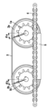
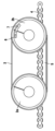
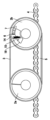
- FIG. 1 is a side view showing the configuration of a chain elongation detection device according to a first embodiment
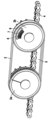
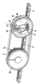
- 1 is a perspective view showing a configuration of a chain elongation detection device according to a first embodiment
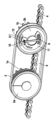
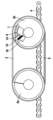
- 1 is a perspective view showing a configuration of a chain elongation detection device according to a first embodiment
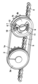
- 5 is a diagram showing an example of a state in which no chain elongation occurs in the chain elongation detection device according to embodiment 1
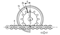
- FIG. 1 is a diagram showing an example of a state in which chain elongation occurs in the chain elongation detection device according to embodiment 1
- FIG. 11 is a diagram showing the relationship between the difference in rotation angle between the second sprocket and the second pulley and chain elongation in the first embodiment.
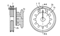
- FIG. 5 is a diagram showing an example of a configuration for detecting a difference in rotation angle between a second sprocket and a second pulley in order to detect elongation of the chain in the first embodiment.
- FIG. FIG. 8 is a diagram illustrating the operation of the configuration shown in FIG. 7 .
- FIG. 8 is a diagram illustrating the operation of the configuration shown in FIG. 7 .
- 1A and 1B are diagrams illustrating a first example of the configuration of a detector that mechanically detects the amount of elongation occurring in a chain.
- 13 is a diagram showing a second example of the configuration of a detector that mechanically detects the amount of elongation occurring in a chain.
- FIG. 13 is a diagram showing a third example of the configuration of a detector that mechanically detects the amount of elongation occurring in a chain.
- FIG. 13 is a diagram showing a third example of the configuration of a detector that mechanically detects the amount of elongation occurring in a chain.
- FIG. 13 is a diagram showing a fourth example of the configuration of a detector that mechanically detects the amount of elongation occurring in a chain.
- FIG. 13 is a diagram showing a fourth example of the configuration of a detector that mechanically detects the amount of elongation occurring in a chain.
- FIG. FIG. 13 is a diagram showing a fifth example of the configuration of a detector that mechanically detects the amount of elongation occurring in a chain.
- FIG. 13 is a diagram showing a fifth example of the configuration of a detector that mechanically detects the amount of elongation occurring in a chain.
- FIG. 13 is a diagram showing a fifth example of the configuration of a detector that mechanically detects the amount of elongation occurring in a chain.
- Fig. 1 is a side view showing the configuration of a chain elongation detection device according to embodiment 1.
- Fig. 2 and Fig. 3 are perspective views showing the configuration of the chain elongation detection device according to embodiment 1.
- the chain elongation detection device according to this embodiment is for detecting elongation of a chain 4, which is a member that transmits power by tension.
- the chain elongation detection device includes a pair of sprockets, a first sprocket 1a and a second sprocket 1b, which rotate by meshing with the chain 4, the elongation of which is to be detected.
- Figure 2 is an oblique view seen from the side of the pair of sprockets.
- the first sprocket 1a and the second sprocket 1b have the same number of teeth and diameter.
- the rotational angle of the first sprocket 1a and the rotational angle of the second sprocket 1b for a specific amount of movement of the chain 4 are equal.
- the chain elongation detection device includes a first pulley 2a fixed coaxially with the first sprocket 1a, which is one of the pair of sprockets described above, and a second pulley 2b fixed coaxially with the second sprocket 1b, which is the other.
- Figure 3 is a perspective view seen from the pulley side.
- a timing belt 3 that transmits rotation between the pulleys is wound around the first pulley 2a and the second pulley 2b.
- the first pulley 2a and the second pulley 2b have the same diameter.
- the rotation angle of the first pulley 2a and the rotation angle of the second pulley 2b for a specific amount of movement of the timing belt 3 are equal.
- the chain elongation detection device also includes a chain guide 5 as a member for guiding the chain 4 so that the chain 4 travels in a direction parallel to a straight line connecting the axial centers of the first sprocket 1a and the second sprocket 1b, as shown in Figures 1 to 3.
- a chain guide 5 as a member for guiding the chain 4 so that the chain 4 travels in a direction parallel to a straight line connecting the axial centers of the first sprocket 1a and the second sprocket 1b, as shown in Figures 1 to 3.
- the chain pitch which is the design dimension between adjacent links of the target chain 4, is known.
- the center distance between the first sprocket 1a and the second sprocket 1b is set to an integer multiple of the chain pitch of the chain 4.
- Each of a pair of sprockets arranged in this manner will have the same meshing state with the chain 4. If the chain 4 is not stretched and the spacing between adjacent links has not changed, the first sprocket 1a and the second sprocket 1b will rotate while maintaining the same rotational angle.
- the first pulley 2a is supported on the same rotation axis as the first sprocket 1a so that they rotate together.
- the first pulley 2a continues to maintain the same rotation angle as the first sprocket 1a as the chain 4 moves.
- the second pulley 2b is supported rotatably on the same rotation axis as the second sprocket 1b, but is supported so that it can rotate independently of the second sprocket 1b.
- the first pulley 2a and the second pulley 2b are connected by a timing belt 3.
- the second pulley 2b rotates at the same rotation angle as the first pulley 2a as the first pulley 2a rotates.
- the rotation angles of the first pulley 2a and the second pulley 2b are maintained in the same state without being affected by the stretching of the chain 4.
- FIG. 4 is a diagram showing an example of a state in which the chain 4 is not stretched in the chain elongation detection device according to embodiment 1.
- the rotation angle ⁇ a of the first sprocket 1a and the rotation angle ⁇ b of the second sprocket 1b are maintained at the same rotation angle ⁇ .
- the rotation angles of the first pulley 2a and the second pulley 2b, which rotate integrally and coaxially with the first sprocket 1a are also the same rotation angle ⁇ .
- Figure 5 is a diagram showing an example of a state in which the chain 4 is elongated in the chain elongation detection device according to embodiment 1.
- the second sprocket 1b has not yet started to mesh with the links of the chain 4 at the point in time when the first sprocket 1a begins to mesh with the links of the chain 4.
- a difference ⁇ corresponding to the elongation of the chain 4 occurs between the rotation angle ⁇ a of the first sprocket 1a and the rotation angle ⁇ b of the second sprocket 1b.
- the rotation angle of the second pulley 2b which rotates independently of the second sprocket 1b, is maintained at the same rotation angle ⁇ a as the rotation angle of the first sprocket 1a and first pulley 2a.
- the above-mentioned rotation angle difference ⁇ occurs between the rotation angle ⁇ a of the second pulley 2b and the rotation angle ⁇ b of the second sprocket 1b.
- the elongation occurring in the chain 4 is mechanically detected by utilizing the difference ⁇ in the rotation angle between the second sprocket 1b and the second pulley 2b on the rotation axis of the second sprocket 1b.
- FIG. 6 is a diagram showing the relationship between the difference ⁇ in the rotational angles between the second sprocket 1b and the second pulley 2b and the elongation of the chain 4 in the first embodiment.
- the second sprocket 1b rotates in accordance with the movement of the meshing chain 4.
- the second pulley 2b rotates in synchronization with the rotation of the first pulley 2a connected by the timing belt 3.
- the first pulley 2a rotates coaxially and integrally with the first sprocket 1a.
- the rotational angle of the second pulley 2b is the same as the rotational angle of the first sprocket 1a.
- the distance between the rotational axes of a pair of sprockets is set to an integer multiple of the chain pitch of the chain 4.
- the chain pitch is a known value defined by a standard.
- the distance from the position where the sprocket and chain 4 mesh to the center of rotation of that sprocket is r. If the chain 4 elongates by a length ⁇ in the region between the first sprocket 1a and the second sprocket 1b, the rotation angle of the second sprocket 1b will deviate from the rotation angle of the first sprocket 1a by a rotation angle difference ⁇ that corresponds to the elongation ⁇ of the chain 4.
- This rotation angle difference ⁇ can be calculated using the following formula (1).
- the distance r from the position where the sprocket and the chain 4 mesh to the center of rotation of the sprocket is a value that is set by design.
- the relationship between the amount of elongation ⁇ of the chain 4 to be detected and the rotation angle difference ⁇ can be uniquely determined.
- the amount of elongation ⁇ of the chain 4 is detected using the rotation angle difference ⁇ .
- FIG. 7 is a diagram showing an example of a configuration for detecting the difference ⁇ in rotation angle between the second sprocket 1b and the second pulley 2b in order to detect the elongation of the chain 4 in embodiment 1.
- the diagram on the right side of FIG. 7 shows a view from the second sprocket 1b side in the axial direction of the second sprocket 1b and the second pulley 2b.
- the diagram on the left side of FIG. 7 shows a cross-sectional view taken along line A-A of the diagram on the right side.
- the chain elongation detection device includes a pin 6 and a hole 7 as an example of a configuration for mechanically detecting the rotation angle difference ⁇ .
- the pin 6 is fixed to the surface side of the second sprocket 1b so as to stand upright in the axial direction of the second sprocket 1b.
- the pin 6 is an example of a structure integrated with the second sprocket 1b.
- the hole 7 is formed on the surface side of the second pulley 2b.
- the pin 6 passes through the hole 7.
- the hole 7 is formed so that the pin 6 can move without contact due to the relative rotation between the second sprocket 1b and the second pulley 2b.
- the hole 7 is formed in a slit shape.
- FIGS. 8 and 9 are diagrams explaining the operation of the configuration shown in FIG. 7.
- FIG. 8 shows the positional relationship between the pin 6 and the hole 7 in the initial state.
- FIG. 9 shows the positional relationship between the pin 6 and the hole 7 when the chain 4 is stretched.
- the second sprocket 1b rotates later than the first sprocket 1a by the amount of elongation of the chain 4. Because the second pulley 2b operates at the same rotation angle as the first sprocket 1a, the hole 7 of the second pulley 2b begins to rotate first relative to the pin 6 fixed to the second sprocket 1b. Compared to the initial state shown in Figure 8, only the hole 7 rotates first, resulting in the state shown in Figure 9. At this time, the relationship between the amount of deviation in the relative positions of the pin 6 and the hole 7 and the amount of elongation of the chain 4 satisfies the above-mentioned formula (1). The amount of elongation of the chain 4 can be mechanically detected from the amount of deviation in the rotation angle between the pin 6 and the hole 7.
- the amount of elongation occurring in the chain 4 is mechanically detected using the difference in the relative amount of movement between the structure integrated with the second sprocket 1b and the second pulley 2b.
- the chain elongation detection device of this embodiment can detect the elongation of the chain 4 used as a power transmission means with a simpler configuration.
- a configuration for processing signals from a sensor device for detecting the elongation of the chain 4 is not required, which can simplify the configuration of the entire device and reduce costs.
- the configuration of the detection unit for detecting the difference in the relative amount of movement between the structure integrated with the second sprocket 1b and the second pulley 2b is not limited to the pin 6 and hole 7, and any mechanical structure can be used.
- FIG. 10 is a diagram showing a first example of the configuration of a detection unit that mechanically detects the amount of elongation occurring in the chain 4.
- a scale 9 along the movement direction of the pin 6 may be provided near the hole 7.
- the scale 9 indicates the amount of movement of the structure integrated with the second sprocket 1b so that it can be visually confirmed. By visually checking the movement of the pin 6 along the scale 9, the user can easily confirm the change in the elongation of the chain 4.
- the scale 9 may display a specific number representing the elongation rate, or the scale 9 may be colored according to the elongation rate. Any method can be used to display the elongation rate and amount of elongation using the scale 9.
- FIG. 11 is a diagram showing a second example of the configuration of a detection unit that mechanically detects the amount of elongation occurring in the chain 4.
- a needle-shaped extension pin 8 may be attached to the tip of the pin 6, which is formed to connect the center of the pin 6 with the center of rotation of the second sprocket 1b and extend outward from the pin 6.
- the second pulley 2b may be equipped with a plate with a scale 9 drawn radially outward.
- the amount of movement of the tip of the extension pin 8 increases in proportion to the length of the extension pin 8, making it easier to see changes in the elongation of the chain 4.
- the chain elongation detector includes a lever 10 for enlarging and displaying the relative displacement of the pin 6 with respect to the hole 7.
- the lever 10 is supported so as to be rotatable about a lever rotation axis A fixed to the second pulley 2b.
- the chain elongation detector includes a base 11 that is fixed to the second pulley 2b so that its position can be adjusted and that moves together with it.
- the chain elongation detector includes a rotational force applying means 12 that applies a rotational force to the lever 10 so that one end of the lever 10 contacts the pin 6.
- a rotating spring can be used as the rotational force applying means 12.
- a scale 9 is drawn on the base 11 on the side opposite to the side where the lever 10 and the pin 6 contact each other.
- One end of the lever 10 contacts the pin 6, and the contact direction is in a direction in which the lever 10 is pushed toward the pin 6 by the movement of the pin 6 caused by the stretching of the chain 4.
- the lever 10 rotates around the lever rotation axis A by the movement of the pin 6.
- the scale 9 indicates the amount of movement of the other end of the lever 10 so that it can be visually confirmed.
- the distance from the lever rotation axis A to the end of the lever 10 on the side on which the scale 9 is drawn may be set to an integer n times the distance from the contact point between the lever 10 and the pin 6 to the lever rotation axis A.
- the relative displacement of the pin 6 can be displayed as n times on the scale 9 of the base 11.
- FIGS. 14 and 15 are diagrams showing a fourth example of the configuration of a detection unit that mechanically detects the amount of elongation occurring in the chain 4.
- the configuration and operation of this fourth example are basically the same as the third example shown in FIGS. 12 and 13.
- a rotational resistance load means 13 is provided instead of the rotational force imparting means 12 in the third example.
- the rotational resistance load means 13 is a resistor that aims to maintain the position of the lever 10 by applying a certain resistance to the rotational movement of the lever 10.
- a resistor using the viscous resistance of oil or sliding friction resistance can be used as the rotational resistance load means 13.
- the lever 10 receives a force from the rotation resistance load means 13 to maintain its position. This causes the lever 10 to continue to maintain the position rotated by the pin 6.
- the lever 10 indicates the maximum amount of displacement rotated by the pin 6 up to that point.
- the maximum amount of elongation of the chain 4 can be known. In this example, it is possible to detect and store whether the elongation of the chain 4 has reached a predetermined reference elongation.
- FIGS. 16, 17, and 18 are diagrams showing a fifth example of the configuration of a detection unit that mechanically detects the amount of elongation occurring in the chain 4.
- the chain elongation detection device includes a detection lever 14 that indicates, by a change in position, that the elongation of the chain 4 has reached a standard, and a lever spring 15 that is a spring for maintaining the position of the detection lever 14.
- the detection lever 14 is rotatable about an axis of rotation fixed to the second pulley 2b.
- the lever spring 15 is an example of a rotational force adding means.
- Figure 16 shows the state of each part when there is no stretch in the chain 4.
- Figure 17 shows the state of each part when there is stretch in the chain 4.
- the pin 6 is positioned relative to the hole 7 so that it does not come into contact with either end of the hole 7. When the chain 4 stretches, the pin 6 moves relative to the hole 7 according to the amount of stretch.
- the rotation angle ⁇ s of the pin 6 when the elongation of the chain 4 reaches ⁇ s can be calculated as ⁇ s ⁇ r, using the distance r from the center of rotation of the second sprocket 1b to the meshing position of the chain 4.
- the detection lever 14 is rotatably supported on a base 16 fixed on the second pulley 2b. In the initial state shown in FIG. 17 where the chain 4 is not stretched, one end of the detection lever 14 is held in a position in contact with the pin 6 by the force of the lever spring 15.
- the chain stretch detection device shown in the above embodiment can be applied to various devices that use a chain as a power transmission mechanism.
- the chain stretch detection device according to the present disclosure can be applied to elevators such as escalators, for example.
- the chain elongation detection device disclosed herein is used to detect elongation of a chain that constitutes a power transmission mechanism.
Landscapes
- Devices For Conveying Motion By Means Of Endless Flexible Members (AREA)
- Escalators And Moving Walkways (AREA)
Abstract
本開示に係るチェーン伸び検知装置は、チェーン(4)に噛み合うことで回転する第1スプロケット(1a)および第2スプロケット(1b)と、第1スプロケット(1a)と同じ回転軸で一体になって回転する第1プーリー(2a)と、第2スプロケット(2b)と同じ回転軸で独立して回転する第2プーリー(2b)と、を備える。第1スプロケット(1a)および第2スプロケット(1b)は、軸中心を結ぶ直線がチェーン(4)の走行方向と平行となるように設置され、軸間距離はチェーン(4)のチェーンピッチの整数倍に設定される。第1プーリー(2a)と第2プーリー(2b)とは、同じ回転角度を維持するようにタイミングベルト(3)によって連結される。第2スプロケット(1b)と一体となった構造物と第2プーリー(2b)との相対的な移動量の差を用いてチェーン(4)に生じる伸び量を機械的に検知する。
Description
本開示は、チェーン伸び検知装置およびエスカレーターに関するものである。
動力伝達手段として用いられるチェーンには、摩耗等を原因として伸びが生じる。特許文献1には、チェーンの伸びを検知する技術が開示されている。
特許文献1に記載の技術においては、チェーンの伸びを検知するために信号の演算処理を行う必要がある。チェーンの伸びの検知のために演算処理を行う構成要素を設けることは、チェーンを動力伝達手段として用いる装置の複雑化あるいはコストアップにつながってしまう。
本開示は、上記のような課題を解決するためのものである。本開示の目的は、動力伝達手段として用いられるチェーンの伸びをより簡易な構成によって検知することである。
本開示に係るチェーン伸び検知装置は、対象となるチェーンに噛み合うことで回転する一対のスプロケットと、前記一対のスプロケットの一方と同じ回転軸で当該一方と一体になって回転する第1プーリーと、前記一対のスプロケットの他方と同じ回転軸で当該他方とは独立して回転する第2プーリーと、を備える。前記一対のスプロケットは、軸中心を結ぶ直線が前記チェーンの走行方向と平行となるように設置され、前記一対のスプロケットの軸間距離は、前記チェーンのチェーンピッチの整数倍に設定され、前記第1プーリーと前記第2プーリーとは、同じ回転角度を維持するようにタイミングベルトによって連結される。本開示に係るチェーン伸び検知装置は、前記他方のスプロケットと一体となった構造物と前記第2プーリーとの相対的な移動量の差を用いて前記チェーンに生じる伸び量を機械的に検知する。
また、本開示に係るエスカレーターは、動力を伝達するために用いられるチェーンと、前記チェーンに噛み合うことで回転する一対のスプロケットと、前記一対のスプロケットの一方と同じ回転軸で当該一方と一体になって回転する第1プーリーと、前記一対のスプロケットの他方と同じ回転軸で当該他方とは独立して回転する第2プーリーと、を備える。前記一対のスプロケットは、軸中心を結ぶ直線が前記チェーンの走行方向と平行となるように設置され、前記一対のスプロケットの軸間距離は、前記チェーンのチェーンピッチの整数倍に設定され、前記第1プーリーと前記第2プーリーとは、同じ回転角度を維持するようにタイミングベルトによって連結される。本開示に係るエスカレーターは、前記他方のスプロケットと一体となった構造物と前記第2プーリーとの相対的な移動量の差を用いて前記チェーンに生じる伸び量を機械的に検知するものである。
また、本開示に係るエスカレーターは、動力を伝達するために用いられるチェーンと、前記チェーンに噛み合うことで回転する一対のスプロケットと、前記一対のスプロケットの一方と同じ回転軸で当該一方と一体になって回転する第1プーリーと、前記一対のスプロケットの他方と同じ回転軸で当該他方とは独立して回転する第2プーリーと、を備える。前記一対のスプロケットは、軸中心を結ぶ直線が前記チェーンの走行方向と平行となるように設置され、前記一対のスプロケットの軸間距離は、前記チェーンのチェーンピッチの整数倍に設定され、前記第1プーリーと前記第2プーリーとは、同じ回転角度を維持するようにタイミングベルトによって連結される。本開示に係るエスカレーターは、前記他方のスプロケットと一体となった構造物と前記第2プーリーとの相対的な移動量の差を用いて前記チェーンに生じる伸び量を機械的に検知するものである。
本開示に係るチェーン伸び検知装置およびエスカレーターにおいては、より簡易な構成によってチェーンの伸びを検知することができる。
以下、実施の形態について、添付の図面を参照して説明する。なお、各図において共通または対応する要素には、同一の符号を付すものとし、本開示では、重複する説明を簡略化または省略する。なお、本開示は、以下に説明する実施の形態に限定されるものではなく、以下の実施の形態によって開示される構成のあらゆる組合せおよび変形例を含み得るものである。
実施の形態1.
図1は、実施の形態1によるチェーン伸び検知装置の構成を示す側面図である。図2および図3は、実施の形態1によるチェーン伸び検知装置の構成を示す斜視図である。本実施の形態に係るチェーン伸び検知装置は、張力によって動力を伝達する部材であるチェーン4の伸びを検知するためのものである。
図1は、実施の形態1によるチェーン伸び検知装置の構成を示す側面図である。図2および図3は、実施の形態1によるチェーン伸び検知装置の構成を示す斜視図である。本実施の形態に係るチェーン伸び検知装置は、張力によって動力を伝達する部材であるチェーン4の伸びを検知するためのものである。
本実施の形態に係るチェーン伸び検知装置は、伸びの検知対象となるチェーン4と噛み合うことで回転する一対のスプロケットとして、第1スプロケット1aおよび第2スプロケット1bを備える。図2は、これら一対のスプロケット側から見た斜視図である。第1スプロケット1aおよび第2スプロケット1bは、歯数および直径が同じである。チェーン4の特定の移動量に対する第1スプロケット1aの回転角度と第2スプロケット1bの回転角度とは、等しくなっている。
本実施の形態に係るチェーン伸び検知装置は、上述した一対のスプロケットの一方である第1スプロケット1aと同軸に固定された第1プーリー2aと、他方である第2スプロケット1bと同軸に固定された第2プーリー2bと、を備える。図3は、これらのプーリー側から見た斜視図である。第1プーリー2aおよび第2プーリー2bには、プーリー間での回転を伝達するタイミングベルト3が巻き掛けられている。第1プーリー2aおよび第2プーリー2bは、直径が同じである。タイミングベルト3の特定の移動量に対する第1プーリー2aの回転角度と第2プーリー2bの回転角度とは、等しくなっている。
また、本実施の形態に係るチェーン伸び検知装置は、図1から図3に示すように、第1スプロケット1aおよび第2スプロケット1bの軸中心を結ぶ直線と平行な方向にチェーン4が走行するように当該チェーン4をガイドするための部材として、チェーンガイド5を備えている。
対象となるチェーン4の隣り合うリンク間の設計寸法であるチェーンピッチは、既知である。第1スプロケット1aおよび第2スプロケット1bの軸間距離は、チェーン4のチェーンピッチの整数倍に設定されている。このように配置された一対のスプロケットのそれぞれは、チェーン4との噛み合い状態が同じになる。チェーン4が伸びておらず、隣り合うリンクの間隔が変化していない場合には、第1スプロケット1aおよび第2スプロケット1bは同じ回転角度を保ちながら回転する。
第1プーリー2aは、第1スプロケット1aと同じ回転軸で且つ一体に回転するように支持されている。第1プーリー2aは、チェーン4の走行に従って、第1スプロケット1aと同じ回転角度を維持し続ける。一方で、第2プーリー2bは、第2スプロケット1bと同じ回転軸で回転可能に支持されているが、第2スプロケット1bとは独立して回転することができるように支持されている。
第1プーリー2aと第2プーリー2bとは、タイミングベルト3によって連結されている。第2プーリー2bは、第1プーリー2aの回転に従って、当該第1プーリー2aと同じ回転角度で回転する。第1プーリー2aの回転角度と第2プーリー2bの回転角度とは、チェーン4の伸び影響を受けずに、同じ状態で維持される。
図4は、実施の形態1によるチェーン伸び検知装置において、チェーン4の伸びが生じていない状態の一例を示す図である。上述の通り、チェーン4に伸びが生じていない状態では、第1スプロケット1aの回転角度θaと第2スプロケット1bの回転角度θbとは、同じ回転角度θで維持される。同時に、第1スプロケット1aと同軸で一体に回転する第1プーリー2aおよび第2プーリー2bの回転角度も、同じ回転角度θとなる。
図5は、実施の形態1によるチェーン伸び検知装置において、チェーン4の伸びが生じている状態の一例を示す図である。チェーン4に伸びが生じた場合、第1スプロケット1aがチェーン4のリンクと噛み合い始めた時点において、第2スプロケット1bはまだチェーン4のリンクとの噛み合いが始まっていない状態となっている。このため、第1スプロケット1aの回転角度θaに対して、第2スプロケット1bの回転角度θbには、チェーン4の伸びに相当する差Δが生じることになる。
一方で、第2スプロケット1bとは独立して回転する第2プーリー2bの回転角度は、第1スプロケット1aおよび第1プーリー2aの回転角度θaと同じ状態で維持される。第2スプロケット1bの回転軸上において、第2プーリー2bの回転角度θaと第2スプロケット1bの回転角度θbとの間には上述した回転角度の差Δが生じる。本実施の形態では、第2スプロケット1bの回転軸上における、第2スプロケット1bと第2プーリー2bとの回転角度の差Δを利用することで、チェーン4に生じる伸びを機械的に検知する。
図6は、実施の形態1における第2スプロケット1bと第2プーリー2bとの回転角度の差Δとチェーン4の伸びとの関係を示す図である。上述の通り、第2スプロケット1bは、噛み合うチェーン4の移動に従い回転する。第2プーリー2bは、タイミングベルト3によって連結された第1プーリー2aの回転と同期して回転する。第1プーリー2aは、第1スプロケット1aと同軸かつ一体に回転する。第2プーリー2bの回転角度は、第1スプロケット1aの回転角度と同じとなる。
上述の通り、本実施の形態では、1対のスプロケットの回転軸同士の間隔は、チェーン4のチェーンピッチの整数倍に設定されている。チェーンピッチは、規格で定められた既知の値である。
ここで、スプロケットとチェーン4とが噛合う位置から当該スプロケットの回転中心までの距離をrとする。第1スプロケット1aと第2スプロケット1bとの間の領域において、長さδの伸びがチェーン4に生じた場合、第2スプロケット1bの回転角度は第1スプロケット1aの回転角度に対して、チェーン4の伸びδに相当する回転角度差Δだけずれることとなる。この回転角度差Δは、次式(1)で計算することができる。
Δ=δ/r ・・・(1)
スプロケットとチェーン4とが噛合う位置から当該スプロケットの回転中心までの距離rは、設計によって設定される値である。検知の対象となるチェーン4の伸び量δと回転角度差Δとの関係は、一意に求めることができる。本実施の形態では、回転角度差Δを用いて、チェーン4の伸び量δを検知する。
図7は、実施の形態1において、チェーン4の伸びを検知するための第2スプロケット1bと第2プーリー2bとの回転角度差Δを検知する構成の一例を示す図である。図7の右側の図は、第2スプロケット1bおよび第2プーリー2bの軸方向視点において第2スプロケット1b側から見た図を示している。図7の左側の図は、右側の図のA-A断面図を示している。
本実施の形態に係るチェーン伸び検知装置は、回転角度差Δを機械的に検知するための構成の一例として、ピン6および孔7を備えている。ピン6は、第2スプロケット1bの表面側部分に、第2スプロケット1bの軸方向に直立するように固定されている。ピン6は、第2スプロケット1bと一体となった構造物の一例である。孔7は、第2プーリー2bの表面側に形成されている。孔7には、ピン6が貫通している。孔7は、第2スプロケット1bと第2プーリー2bとの間の相対的な回転によってピン6が接触することなく移動できるように形成されている。一例として、孔7は、スリット状に形成されている。
図8および図9は、図7に示す構成の動作を説明する図である。図8は、初期状態におけるピン6と孔7との位置関係を示している。図9は、チェーン4に伸びが生じた場合のピン6と孔7との位置関係を示したものである。
チェーン4に伸びが生じていない状態では、第2スプロケット1bと第2プーリー2bとの間に回転角度の差はない。チェーン4に伸びがない状態の場合、ピン6と孔7との位置関係は、図8に示す状態で保たれる。
チェーン4に伸びがある場合、第2スプロケット1bは、チェーン4の伸びの分、第1スプロケット1aに対して遅れて回転する。第2プーリー2bは第1スプロケット1aと同じ回転角度で動作するため、第2スプロケット1bに固定されたピン6に対して、第2プーリー2bの孔7が先に回転を始める。図8に示す初期状態に対して孔7だけが先に回転し、図9に示すような状態となる。この時のピン6と孔7との相対位置のずれ量とチェーン4の伸び量との間には、上述した式(1)の関係が成り立つ。ピン6と孔7との回転角度のずれ量から、チェーン4の伸び量を機械的に検知することができる。
以上に示したように、本実施の形態においては、第2スプロケット1bと一体となった構造物と第2プーリー2bとの相対的な移動量の差を用いて、チェーン4に生じる伸び量を機械的に検知する。本実施の形態に係るチェーン伸び検知装置であれば、動力伝達手段として用いられるチェーン4の伸びをより簡易な構成によって検知することができる。例えば、チェーン4の伸びの検知のためのセンサ機器からの信号を演算処理するための構成が不要であり、装置全体の構成の簡素化および低コスト化が実現できる。なお、第2スプロケット1bと一体となった構造物と第2プーリー2bとの相対的な移動量の差を検知するための検知部の構成は、ピン6および孔7に限られず、任意の機械的な構造物を用いることができる。
図10は、チェーン4に生じる伸び量を機械的に検知する検知部の構成の第1の例を示す図である。図10に示すように、孔7の近傍に、ピン6の移動方向に沿った目盛9が備えられていてもよい。目盛9は、第2スプロケット1bと一体となった構造物の移動量を視認できるように表示するものである。ユーザは、目盛9に沿ったピン6の動きを目視することにより、チェーン4の伸びの変化を容易に確認することができる。なお、この目盛9には、具体的な伸び率の数字を表示してもよいし、目盛9に伸び率に応じた色を着色してもよい。目盛9による伸び率および伸び量の表示方法には、任意の手法を用いることができる。
図11は、チェーン4に生じる伸び量を機械的に検知する検知部の構成の第2の例を示す図である。図11に示すように、ピン6の先端部分に、ピン6の中心と第2スプロケット1bの回転中心とを結んでピン6の外側に向かって伸びるように形成された、針状の延長ピン8が装着されてもよい。第2プーリー2bには、径方向外側に向かって目盛9が描かれたプレートが装備されていてもよい。図11の例であれば、延長ピン8の先端の移動量は当該延長ピン8の長さに比例して大きくなるため、チェーン4の伸びの変化をより見やすくすることができる。
図12および図13は、チェーン4に生じる伸び量を機械的に検知する検知部の構成の第3の例を示す図である。本例において、チェーン伸び検知装置は、ピン6の孔7に対する相対的な変位量を拡大表示するためのレバー10を備える。レバー10は、第2プーリー2bに固定されたレバー回転軸Aを中心に回転可能に支持されている。また、本例において、チェーン伸び検知装置は、第2プーリー2bに対して位置を調整可能なように固定されて一体に動くベース11を備える。また、本例において、チェーン伸び検知装置は、レバー10の一側の端部をピン6に接触させるようにレバー10に回転力を与える回転力付与手段12を備える。回転力付与手段12には、例えば、回転バネを用いることができる。ベース11上には、レバー10とピン6とが接触している側と反対側の部分に目盛9が描かれている。
レバー10の一側の端部はピン6と接触し、接触方向はチェーン4の伸びによって生じるピン6の動きによってピン6に向けて押される方向となっている。レバー10は、ピン6の移動によってレバー回転軸Aを中心に回転する。目盛9は、レバー10の他端の端部の移動量を視認できるように表示する。ここで、レバー10とピン6との接触点からレバー回転軸Aまでの距離に対して、レバー回転軸Aから目盛9の描かれた側のレバー10の端部まで距離を長くするとよい。例えば、レバー10とピン6との接触点からレバー回転軸Aまでの距離に対して、レバー回転軸Aから目盛9の描かれた側のレバー10の端部まで距離を整数n倍に設定してもよい。この構成により、ピン6の相対的な変位量を、ベース11の目盛9上でn倍として表示することができる。
図14および図15は、チェーン4に生じる伸び量を機械的に検知する検知部の構成の第4の例を示す図である。この第4の例における構成および動作は、基本的には、図12および図13に示した第3の例と同様である。本例においては、第3の例における回転力付与手段12に代えて、回転抵抗負荷手段13を備えている。回転抵抗負荷手段13は、レバー10の回転動作に一定の抵抗を負荷することで、レバー10の姿勢を保持することを目的とする抵抗器である。回転抵抗負荷手段13には、例えば、オイルの粘性抵抗あるいは摺動摩擦抵抗を用いた抵抗器を利用することができる。
本例において、レバー10は、回転抵抗負荷手段13により、姿勢を保持する力を受けている。これにより、レバー10はピン6によって回転させられた姿勢を保持し続けることとなる。レバー10は、その時点までにピン6によって回転させられた最大の変位量を示すこととなる。レバー10がベース11上の目盛に示す値を読み取ることで、チェーン4の伸び量の最大値を知ることができる。本例では、チェーン4の伸びが予め基準とする伸びに達しているかを検知して記憶することができる。
また、図16、図17および図18は、チェーン4に生じる伸び量を機械的に検知する検知部の構成の第5の例を示す図である。本例において、チェーン伸び検知装置は、チェーン4の伸びが基準に達したことを姿勢の変化で示す検知レバー14と、検知レバー14の姿勢を保持するためのバネであるレバー用バネ15を備えている。検知レバー14は、第2プーリー2bに固定された回転軸を中心に回転可能である。レバー用バネ15は、回転力付加手段の一例である。
図16は、チェーン4に伸びが生じていない状態の各部品の状態を示している。図17は、チェーン4に伸びが生じている状態の各部品の状態を示している。ピン6は、孔7に対して、当該孔7の両端には接触しない位置になるように配置されている。チェーン4の伸びがある場合には、その伸びの量に応じて、ピン6は孔7に対して移動する。
チェーン4の伸び量がδsに達した場合のピン6の回転角度θsは、第2スプロケット1bの回転中心とチェーン4との噛み合い位置までの距離rを用いて、δs×rとして求めることができる。
検知レバー14は、第2プーリー2b上に固定されたベース16に回転可能に支持されている。図17に示すチェーン4に伸びのない初期状態では、レバー用バネ15の力によって、検知レバー14の一側の端部がピン6に接する姿勢で保持されている。
この状態でチェーン4に伸びが生じると、ピン6は孔7の中において検知レバー14を押す。これによって検知レバー14は回転する。さらにチェーン4の伸びが進むと、ピン6によって動かされる検知レバー14の回転角度も大きくなり、やがて、図18に示すような状態となり、最終的にレバー用バネ15による回転力がゼロになる。ここからさらに検知レバー14が移動すると、レバー用バネ15による検知レバー14に与える回転力の方向は逆転する。すると、検知レバー14は、これまでと反対方向に回転し、第2プーリー2bに設置されたストッパーと接触する位置で停止する。図18は検知レバー14がこの姿勢に達した状態を示すものであり、その後、検知レバー14はレバー用バネ15の力によりこの姿勢を維持する。検知すべき基準の伸び量において検知レバー14が図18に示す姿勢となるように各部品の位置関係を設計することで、検知レバー14の姿勢を目視してチェーン4の伸び量が基準に達したかどうかを確認することができる。
上記の実施の形態に示したチェーン伸び検知装置は、動力伝達機構としてチェーンを用いた各種の機器に適用することができる。本開示に係るチェーン伸び検知装置は、例えば、エスカレーターのような昇降機に適用することができる。
本開示に係るチェーン伸び検知装置は、動力伝達機構を構成するチェーンの伸びを検知するために利用される。
1a 第1スプロケット、 1b 第2スプロケット、 2a 第1プーリー、 2b 第2プーリー、 3 タイミングベルト、 4 チェーン、 5 チェーンガイド、 6 ピン、 7 孔、 8 延長ピン、 9 目盛、 10 レバー、 11 ベース、 12 回転力付与手段、 13 回転抵抗負荷手段、 14 検知レバー、 15 レバー用バネ、 16 ベース
Claims (6)
- 対象となるチェーンに噛み合うことで回転する一対のスプロケットと、
前記一対のスプロケットの一方と同じ回転軸で当該一方と一体になって回転する第1プーリーと、
前記一対のスプロケットの他方と同じ回転軸で当該他方とは独立して回転する第2プーリーと、
を備え、
前記一対のスプロケットは、軸中心を結ぶ直線が前記チェーンの走行方向と平行となるように設置され、
前記一対のスプロケットの軸間距離は、前記チェーンのチェーンピッチの整数倍に設定され、
前記第1プーリーと前記第2プーリーとは、同じ回転角度を維持するようにタイミングベルトによって連結され、
前記他方のスプロケットと一体となった構造物と前記第2プーリーとの相対的な移動量の差を用いて前記チェーンに生じる伸び量を機械的に検知することを特徴とするチェーン伸び検知装置。 - 前記他方のスプロケットと一体となった構造物と前記第2プーリーとの相対的な移動量の差を用いて前記チェーンに生じる伸び量を機械的に検知する検知部として、
前記構造物の移動量を表示する目盛を備えたことを特徴とする請求項1に記載のチェーン伸び検知装置。 - 前記他方のスプロケットと一体となった構造物と前記第2プーリーとの相対的な移動量の差を用いて前記チェーンに生じる伸び量を機械的に検知する検知部として、
前記第2プーリーに固定されたレバー回転軸を中心に回転可能に支持されたレバーと、
前記レバーの一側の端部を前記構造物に接触させるように前記レバーに回転力を与える回転力付与手段と、
前記レバーの他側の端部の移動量を表示する目盛と、
を備え、
前記レバーの一側の端部と前記構造物との接触点から前記レバー回転軸までの距離に対して、前記レバー回転軸から前記レバーの他側の端部までの距離が長いことを特徴とする請求項1に記載のチェーン伸び検知装置。 - 前記他方のスプロケットと一体となった構造物と前記第2プーリーとの相対的な移動量の差を用いて前記チェーンに生じる伸び量を機械的に検知する検知部として、
前記第2プーリーに固定されたレバー回転軸を中心に回転可能に支持され、一側の端部を前記構造物に接触した状態で回転するレバーと、
前記レバーの回転に対して抵抗を負荷する回転抵抗負荷手段と、
前記レバーの他側の端部の移動量を表示する目盛と、
を備え、
前記レバーの一側の端部と前記構造物との接触点から前記レバー回転軸までの距離に対して、前記レバー回転軸から前記レバーの他側の端部までの距離が長いことを特徴とする請求項1に記載のチェーン伸び検知装置。 - 前記他方のスプロケットと一体となった構造物と前記第2プーリーとの相対的な移動量の差を用いて前記チェーンに生じる伸び量を機械的に検知する検知部として、
前記第2プーリーに固定された回転軸を中心に回転可能に支持された検知レバーと、
前記検知レバーの姿勢に応じた回転力を前記検知レバーに負荷する回転力負荷手段と、
を備え、
前記検知レバーは、一側の端部が前記構造物と接触した状態で前記構造物の移動によって回転し、
前記構造物の移動量が前記チェーンの伸び量が予め設定した基準に達した際における移動量に達した時に、前記構造物と接触する方向とは逆の方向に前記検知レバーが姿勢を変化させるように前記回転力負荷手段による回転力の方向が変化することを特徴とする請求項1に記載のチェーン伸び検知装置。 - 動力を伝達するために用いられるチェーンと、
前記チェーンに噛み合うことで回転する一対のスプロケットと、
前記一対のスプロケットの一方と同じ回転軸で当該一方と一体になって回転する第1プーリーと、
前記一対のスプロケットの他方と同じ回転軸で当該他方とは独立して回転する第2プーリーと、
を備え、
前記一対のスプロケットは、軸中心を結ぶ直線が前記チェーンの走行方向と平行となるように設置され、
前記一対のスプロケットの軸間距離は、前記チェーンのチェーンピッチの整数倍に設定され、
前記第1プーリーと前記第2プーリーとは、同じ回転角度を維持するようにタイミングベルトによって連結され、
前記他方のスプロケットと一体となった構造物と前記第2プーリーとの相対的な移動量の差を用いて前記チェーンに生じる伸び量を機械的に検知することを特徴とするエスカレーター。
Priority Applications (2)
| Application Number | Priority Date | Filing Date | Title |
|---|---|---|---|
| PCT/JP2023/021246 WO2024252594A1 (ja) | 2023-06-07 | 2023-06-07 | チェーン伸び検知装置およびエスカレーター |
| JP2025525556A JPWO2024252594A1 (ja) | 2023-06-07 | 2023-06-07 |
Applications Claiming Priority (1)
| Application Number | Priority Date | Filing Date | Title |
|---|---|---|---|
| PCT/JP2023/021246 WO2024252594A1 (ja) | 2023-06-07 | 2023-06-07 | チェーン伸び検知装置およびエスカレーター |
Publications (1)
| Publication Number | Publication Date |
|---|---|
| WO2024252594A1 true WO2024252594A1 (ja) | 2024-12-12 |
Family
ID=93795629
Family Applications (1)
| Application Number | Title | Priority Date | Filing Date |
|---|---|---|---|
| PCT/JP2023/021246 Ceased WO2024252594A1 (ja) | 2023-06-07 | 2023-06-07 | チェーン伸び検知装置およびエスカレーター |
Country Status (2)
| Country | Link |
|---|---|
| JP (1) | JPWO2024252594A1 (ja) |
| WO (1) | WO2024252594A1 (ja) |
Citations (6)
| Publication number | Priority date | Publication date | Assignee | Title |
|---|---|---|---|---|
| JPH09287942A (ja) * | 1996-04-24 | 1997-11-04 | Nkk Corp | リンクチェーンの伸び量測定装置 |
| JPH10170206A (ja) * | 1996-12-09 | 1998-06-26 | Nkk Corp | リンクチェーンの伸び量測定装置 |
| JP2008068960A (ja) * | 2006-09-13 | 2008-03-27 | Mitsubishi Electric Building Techno Service Co Ltd | エスカレーター踏段チェーンの伸び量測定装置 |
| JP2017019616A (ja) * | 2015-07-09 | 2017-01-26 | 東芝エレベータ株式会社 | 乗客コンベア用チェーン伸び検出装置および乗客コンベア |
| JP2022029830A (ja) * | 2020-08-05 | 2022-02-18 | 東芝エレベータ株式会社 | チェーン伸び検出装置 |
| WO2023286277A1 (ja) * | 2021-07-16 | 2023-01-19 | 三菱電機株式会社 | チェーン伸び検知装置 |
-
2023
- 2023-06-07 WO PCT/JP2023/021246 patent/WO2024252594A1/ja not_active Ceased
- 2023-06-07 JP JP2025525556A patent/JPWO2024252594A1/ja active Pending
Patent Citations (6)
| Publication number | Priority date | Publication date | Assignee | Title |
|---|---|---|---|---|
| JPH09287942A (ja) * | 1996-04-24 | 1997-11-04 | Nkk Corp | リンクチェーンの伸び量測定装置 |
| JPH10170206A (ja) * | 1996-12-09 | 1998-06-26 | Nkk Corp | リンクチェーンの伸び量測定装置 |
| JP2008068960A (ja) * | 2006-09-13 | 2008-03-27 | Mitsubishi Electric Building Techno Service Co Ltd | エスカレーター踏段チェーンの伸び量測定装置 |
| JP2017019616A (ja) * | 2015-07-09 | 2017-01-26 | 東芝エレベータ株式会社 | 乗客コンベア用チェーン伸び検出装置および乗客コンベア |
| JP2022029830A (ja) * | 2020-08-05 | 2022-02-18 | 東芝エレベータ株式会社 | チェーン伸び検出装置 |
| WO2023286277A1 (ja) * | 2021-07-16 | 2023-01-19 | 三菱電機株式会社 | チェーン伸び検知装置 |
Also Published As
| Publication number | Publication date |
|---|---|
| JPWO2024252594A1 (ja) | 2024-12-12 |
Similar Documents
| Publication | Publication Date | Title |
|---|---|---|
| JP2826556B2 (ja) | 工業用ロボツト | |
| US10710844B2 (en) | Chain stretch detection device, chain stretch detection method, and passenger conveyor | |
| US11541963B2 (en) | Adjustment mechanism and drive | |
| CN105366523A (zh) | 乘客输送机的链条单方伸长检测装置 | |
| JPH0212878B2 (ja) | ||
| WO2024252594A1 (ja) | チェーン伸び検知装置およびエスカレーター | |
| JP7601230B2 (ja) | チェーン伸び検知装置 | |
| CN101532555A (zh) | 用于拉伸传动链条的装置 | |
| JP2007040788A (ja) | かみあい伝達誤差の測定装置および測定方法 | |
| US6280358B1 (en) | Gate drive assembly | |
| IL157036A (en) | Non-slip transmissions particularly useful as continuously-variable transmissions and transmission members thereof | |
| JP3833436B2 (ja) | 電線色替え検尺装置 | |
| JP4663361B2 (ja) | 乗客コンベヤの移動手摺駆動装置 | |
| US9579930B2 (en) | Printing device and tire marking apparatus | |
| CN100567125C (zh) | 乘客输送机的扶手驱动装置 | |
| JP3540059B2 (ja) | パワーステアリングの入力トルク検出装置 | |
| JP4631688B2 (ja) | 噛合伝達誤差測定装置 | |
| JP5427333B2 (ja) | スリットコイル巻取り機のストリップ検知センサー保持装置 | |
| KR101252108B1 (ko) | 모션 비간섭 케이블 구동장치 | |
| JP2009115591A (ja) | 動力伝達チェーンの検査方法および検査装置 | |
| CN110282520B (zh) | 手动测试装置 | |
| JP2015197410A (ja) | レーダ評価装置 | |
| JPH0599287A (ja) | ベルト式変速機の操作力測定装置 | |
| JP3852903B2 (ja) | 電動レボルバ | |
| JPS6238041Y2 (ja) |
Legal Events
| Date | Code | Title | Description |
|---|---|---|---|
| 121 | Ep: the epo has been informed by wipo that ep was designated in this application |
Ref document number: 23940695 Country of ref document: EP Kind code of ref document: A1 |
|
| ENP | Entry into the national phase |
Ref document number: 2025525556 Country of ref document: JP Kind code of ref document: A |
|
| WWE | Wipo information: entry into national phase |
Ref document number: 2025525556 Country of ref document: JP |
|
| NENP | Non-entry into the national phase |
Ref country code: DE |