WO2024252592A1 - 形彫放電加工機 - Google Patents
形彫放電加工機 Download PDFInfo
- Publication number
- WO2024252592A1 WO2024252592A1 PCT/JP2023/021244 JP2023021244W WO2024252592A1 WO 2024252592 A1 WO2024252592 A1 WO 2024252592A1 JP 2023021244 W JP2023021244 W JP 2023021244W WO 2024252592 A1 WO2024252592 A1 WO 2024252592A1
- Authority
- WO
- WIPO (PCT)
- Prior art keywords
- imaging device
- spindle
- workpiece
- contact detection
- die
- Prior art date
- Legal status (The legal status is an assumption and is not a legal conclusion. Google has not performed a legal analysis and makes no representation as to the accuracy of the status listed.)
- Ceased
Links
Images


Classifications
-
- B—PERFORMING OPERATIONS; TRANSPORTING
- B23—MACHINE TOOLS; METAL-WORKING NOT OTHERWISE PROVIDED FOR
- B23H—WORKING OF METAL BY THE ACTION OF A HIGH CONCENTRATION OF ELECTRIC CURRENT ON A WORKPIECE USING AN ELECTRODE WHICH TAKES THE PLACE OF A TOOL; SUCH WORKING COMBINED WITH OTHER FORMS OF WORKING OF METAL
- B23H1/00—Electrical discharge machining, i.e. removing metal with a series of rapidly recurring electrical discharges between an electrode and a workpiece in the presence of a fluid dielectric
-
- B—PERFORMING OPERATIONS; TRANSPORTING
- B23—MACHINE TOOLS; METAL-WORKING NOT OTHERWISE PROVIDED FOR
- B23H—WORKING OF METAL BY THE ACTION OF A HIGH CONCENTRATION OF ELECTRIC CURRENT ON A WORKPIECE USING AN ELECTRODE WHICH TAKES THE PLACE OF A TOOL; SUCH WORKING COMBINED WITH OTHER FORMS OF WORKING OF METAL
- B23H11/00—Auxiliary apparatus or details, not otherwise provided for
-
- B—PERFORMING OPERATIONS; TRANSPORTING
- B23—MACHINE TOOLS; METAL-WORKING NOT OTHERWISE PROVIDED FOR
- B23H—WORKING OF METAL BY THE ACTION OF A HIGH CONCENTRATION OF ELECTRIC CURRENT ON A WORKPIECE USING AN ELECTRODE WHICH TAKES THE PLACE OF A TOOL; SUCH WORKING COMBINED WITH OTHER FORMS OF WORKING OF METAL
- B23H7/00—Processes or apparatus applicable to both electrical discharge machining and electrochemical machining
- B23H7/26—Apparatus for moving or positioning electrode relatively to workpiece; Mounting of electrode
Definitions
- This disclosure relates to a die-sinking electric discharge machine.
- a die-sinking EDM machine is a device that performs die-sinking EDM, which transfers the shape of the machining electrode onto a workpiece called a workpiece.
- the workpiece is first set on the machine table, which is installed in a machining tank filled with insulating machining fluid such as oil or water.
- the highly precisely machined machining electrode is brought closer to the workpiece, and an electric current is passed through the machining electrode to cause discharge.
- the workpiece is machined while maintaining a small constant distance between the workpiece and the machining electrode, for example about several tens of ⁇ m. This gap between the workpiece and the machining electrode is called the discharge gap.
- the discharge gap is called the discharge gap.
- the workpiece In die-sinking EDM, the workpiece is removed from the machine platen after machining and checked to see if its shape and dimensional accuracy meet the requirements. If the check shows that it does not meet the requirements, additional processing is carried out on the workpiece. When additional processing is carried out, the workpiece must be set on the machine platen again, which means it takes time before re-machining of the workpiece can begin. In addition, once the workpiece has been removed from the machine platen, it is extremely difficult to reproduce its original state with high precision and attach it in the exact same position. Furthermore, even if the position of the workpiece can be perfectly reproduced, if time has passed, the positions of the machine and tools will change, and even if the workpiece is re-machined to correct the dimensions, the corrections may not be correct.
- Patent Document 1 a camera is attached to the spindle on which the tool is attached, alongside the tool. The camera moves in sync with the tool. Images obtained by the camera are automatically recognized by a recognition device and are then displayed on a monitor. The user can confirm the shape and dimensions of the workpiece from the displayed image.
- Patent Document 1 when the camera described in Patent Document 1 is applied to a die-sinking electric discharge machine rather than a general machine tool, there is a problem that the camera lens becomes dirty due to the oily smoke generated during the die-sinking electric discharge machining, making it impossible to capture clear images, and there is also a possibility that the internal circuit board of the camera may break down.
- the present disclosure has been made in consideration of the above, and aims to provide a die-sinking electric discharge machine that can check the shape and dimensions of a workpiece without removing the workpiece from the base, while preventing contamination of the lens of the imaging device and malfunction of the imaging device.
- the die-sinking electric discharge machine comprises a spindle, a machining electrode that is detachably attached to the spindle and machines the workpiece by non-contact discharge of electric discharge on the workpiece placed in an insulating machining fluid, an imaging device that is replaced with the machining electrode and detachably attached to the spindle and photographs the workpiece machined by the machining electrode and obtains imaging data showing the shape of the workpiece after machining, a contact detection unit that is connected to the spindle and detects contact if the imaging device comes into contact with the workpiece when the imaging device is attached to the spindle, and an NC device that controls the movement and stopping of the spindle, and the NC device is characterized in that when the contact detection unit detects the contact, it brings the movement of the spindle to an emergency stop.
- the die-sinking electric discharge machine disclosed herein has the advantage of being able to check the shape and dimensions of the workpiece without removing it from the base, while preventing contamination of the lens of the imaging device and damage to the imaging device.
- FIG. 1 is a diagram showing a configuration of a die-sinking electric discharge machine according to a first embodiment
- FIG. 1 is a diagram showing an internal configuration of a control box provided in a die-sinking electric discharge machine according to a first embodiment
- FIG. 2 is a schematic diagram showing a method for imaging and checking a workpiece in the die-sinking electric discharge machine according to the first embodiment
- a flowchart showing the flow of processing by the NC device and the control box provided in the die-sinking electric discharge machine according to the first embodiment.
- FIG. 1 is a diagram showing an example of the configuration of an ATC provided in a die-sinking electric discharge machine according to a first embodiment
- FIG. 1 is a diagram showing an example of the configuration of a processing circuit provided in a control box according to a first embodiment when the processing circuit is realized by a processor and a memory;
- FIG. 1 is a diagram showing an example of a processing circuit in a control box according to a first embodiment, the processing circuit being configured with dedicated hardware;
- FIG. 1 is a diagram showing an internal configuration of a power supply panel provided in a die-sinking electric discharge machine according to a first embodiment;
- FIG. 1 is a diagram showing an internal configuration of a numerical control device (NC device) provided in a die-sinking electric discharge machine according to a first embodiment.
- NC device numerical control device
- FIG. 1 is a diagram showing a wiring configuration when a machining electrode is attached to a die-sinking electric discharge machine according to a first embodiment
- FIG. 2 is a diagram showing a wiring configuration when an imaging device and a control box are attached in the die-sinking electric discharge machine according to the first embodiment
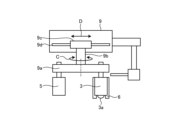
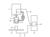
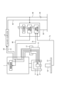
- Embodiment 1 is a diagram showing the configuration of a die-sinking electric discharge machine according to embodiment 1.
- the die-sinking electric discharge machine 100 includes a spindle 1, an electrode chuck 2, an imaging device 3, a control box 4, a machining electrode 5, a contact detection circuit 7, an ATC (Automatic Tool Changer) 9, a power supply panel 10, and a surface plate 21.
- the power supply panel 10 has a contact detection unit 70.
- an electrode chuck 2 is provided on the spindle 1 of the die-sinking electric discharge machine 100.
- the electrode chuck 2 is a mounting fixture for mounting the imaging device 3 or the machining electrode 5 to the spindle 1.
- the imaging device 3 or the machining electrode 5 is detachably fixed to the spindle 1 by the electrode chuck 2.
- the imaging device 3 and the machining electrode 5 are never both mounted on the spindle 1 at the same time; only one of them is always mounted on the spindle 1.
- the example in FIG. 1 shows the imaging device 3 mounted on the electrode chuck 2.
- the imaging device 3 has a lens 3a at its lower end.
- the lens 3a is disposed facing the workpiece 16.
- the imaging device 3 is powered via the control box 4.
- the imaging device 3 and the control box 4 are connected via a power line 41 for supplying power and a signal line 45 for transmitting imaging data.
- the imaging device 3 photographs the workpiece 16.
- the imaging device 3 then transmits the imaging data acquired by the photographing to the control box 4 via the signal line 45.
- Power is supplied to the imaging device 3 from the power source 30 via the control box 4.
- the power source 30 is an external power source such as an outlet.
- the power source 30 is composed of an AC power source such as a commercial power source, but may be a DC power source such as a storage battery.
- the imaging device 3 is composed of, for example, a camera.
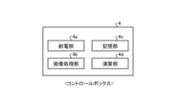
- FIG. 2 is a diagram showing the internal configuration of a control box provided in the die-sinking electric discharge machine according to the first embodiment.
- the control box 4 has a power supply unit 4a, an image processing unit 4b, a memory unit 4c, and a calculation unit 4d.
- the power supply unit 4a supplies power to the imaging device 3 using power from the power source 30.
- the image processing unit 4b processes the imaging data acquired by the imaging device 3 to generate image data 15.
- the memory unit 4c stores the operation program of the control box 4 and stores various data such as the calculation results of the control box 4.
- the calculation unit 4d performs various calculations to confirm the shape and dimensions of the workpiece 16.
- FIG. 2 is an example of the control box 4, and is not limited to this.
- the control box 4 does not necessarily have all of the parts shown in FIG. 2, and may have other configurations other than the parts shown in FIG. 2. Furthermore, some or all of the parts of the control box 4 in FIG. 2 may be composed of a cloud server. Furthermore, the control box 4 may be composed of a server. In this case, the control box 4 may be installed near the die-sinking electric discharge machine 100, or may be installed in a remote location. If the control box 4 is installed in a remote location, the control box 4 and the die-sinking electric discharge machine 100 may be connected via a network such as the Internet. In addition, in the example of FIG. 1, the control box 4 and the power supply panel 10 are configured separately, but this is not limited to the example of FIG. 1. In other words, the control box 4 may be mounted inside the power supply panel 10, or may be provided outside the power supply panel 10.
- the machining electrode 5 is attached to the spindle 1 by the electrode chuck 2.
- the machining electrode 5 is machined with high precision into a shape that is the inverse of the finished shape of the workpiece 16.
- the machining electrode 5 is made of, for example, copper or graphite, and is conductive.
- the machining electrode 5 may also be made of other materials such as tungsten, which is conductive only at temperatures higher than a certain temperature.
- the machining electrode 5 machines the workpiece 16 by non-contact discharge to the workpiece 16 placed in an insulating machining liquid.
- the workpiece 16 is placed in a machining tank filled with machining fluid.
- the machining electrode 5 is brought close to the workpiece 16, and a current is passed through the machining electrode 5 to cause discharge.
- the workpiece 16 is machined into a three-dimensional shape that is the inverse of the shape of the machining electrode 5.
- the shape of the workpiece 16 after machining is sometimes called the product shape. Note that by using the ATC 9, the machining electrode 5 and the imaging device 3 can be automatically replaced on the spindle 1 by program operation, without the user having to replace them manually.
- the machining fluid used in die-sinking electric discharge machining is composed of an insulating liquid such as water or oil.
- Dielectric breakdown is a phenomenon in which the electrical resistance drops suddenly and a large current flows when the electric field to an insulator exceeds a threshold value.
- Dielectric breakdown causes a pulse current to flow instantly, generating a high-density discharge state called an arc column, and the surface of the workpiece 16 becomes locally hot, for example, at about 6000 to 7000°C. This melts the workpiece 16, which is made of metal.
- the workpiece 16 is machined until it finally takes on the product shape.
- the imaging device 3 has a housing (not shown), an imaging device cover 6 attached to cover the housing, a lens 3a, and an electric section 3b (see FIG. 9).
- the housing forms the outer shell of the imaging device 3.
- the electric section 3b includes an internal circuit board that realizes various functions of the imaging device 3.
- the imaging device cover 6 is conductive. As shown in FIG. 1, the imaging device cover 6 has, for example, a cylindrical shape. The lower end of the imaging device cover 6 is open. The lens 3a provided at the lower end of the imaging device 3 is exposed to the outside from the opening of the imaging device cover 6. When the imaging device 3 is attached to the spindle 1, the lens 3a and the workpiece 16 face each other.
- the imaging device cover 6 is connected to a contact detection circuit 7 of the die-sinking electric discharge machine 100.
- the contact detection circuit 7 has a first contact detection line 7a and a second contact detection line 7b.
- the first contact detection line 7a connects the surface plate 21 installed in the processing tank (not shown) and the contact detection unit 70.
- the second contact detection line 7b connects the imaging device cover 6 and the contact detection unit 70.
- the spindle control unit 72a in the numerical control device (hereinafter referred to as NC device) 72 (described later) provided in the power supply panel 10 immediately brings the spindle 1 to an emergency stop. This makes it possible to minimize damage to the imaging device 3 and the workpiece 16. It is desirable that the lower end of the imaging device cover 6 is at the same height as the lens 3a of the imaging device 3 or extend to a position lower than the lens 3a. In the explanation of the first embodiment, "contact between the imaging device cover 6 of the imaging device 3 and the workpiece 16" is sometimes referred to as "contact between the imaging device 3 and the workpiece 16" for the sake of simplicity.
- the die-sinking electric discharge machine 100 is provided with an ATC 9 that replaces the machining electrode 5 and the imaging device 3 on the spindle 1.
- the ATC 9 replaces the machining electrode 5 and the imaging device 3 on the spindle 1 in response to a signal input from the outside.
- the signal input from the outside is, for example, a command from an ATC control unit 72b in an NC device 72 described later and provided on the power supply panel 10.
- the NC device 72 determines that machining of the workpiece 16 is completed, it outputs a command to the ATC 9 to remove the machining electrode 5 from the spindle 1 and attach the imaging device 3 to the spindle 1 instead of the machining electrode 5.
- the NC device 72 when the NC device 72 receives a command from the PC 8 to remachine the workpiece 16, it outputs a command to the ATC 9 to remove the imaging device 3 from the spindle 1 and attach the machining electrode 5 to the spindle 1 instead of the imaging device 3. Based on these commands from the NC device 72, the ATC 9 automatically attaches and detaches the machining electrode 5 or the imaging device 3 to the spindle 1. The machining electrode 5 or imaging device 3 removed from the spindle 1 is returned to the magazine 9a of the ATC 9.
- the ATC 9 is sometimes called an automatic tool changer.
- the imaging device 3 is provided with a first connector terminal 12 for connector connection.
- the spindle 1 is provided with a second connector terminal 13 for connector connection.
- a wired connection between the imaging device 3 and the control box 4, as well as a wired connection between the imaging device cover 6 and the contact detection unit 70 is possible.
- the main body of the first connector terminal 12 may be attached to the imaging device cover 6 instead of the imaging device 3.
- the first connector terminal 12 is not provided on the processing electrode 5.
- FIG. 14 is a diagram showing the internal configuration of a numerical control device (NC unit) provided in the die-sinking electric discharge machine according to the first embodiment. As shown in FIG.
- the NC unit 72 is provided with a spindle control unit 72a, an ATC control unit 72b, and a machining control unit 72c.
- the spindle control unit 72a controls the movement and stopping operation of the spindle 1, and performs an emergency stop of the spindle 1 in the event of an emergency.
- the ATC control unit 72b controls the operation of the ATC 9 to cause the ATC 9 to replace the machining electrode 5 with the imaging device 3.
- the machining control unit 72c supplies power to the machining electrode 5 by outputting a power command to the power supply unit 71 in the power supply panel 10.
- the machining control unit 72c also controls the value of the machining voltage at the machining electrode 5.
- the power supply panel 10 is connected to the power supply 30.
- the power supply panel 10 is also connected to the earth 11 by the earth wire 44.
- the surface plate 21 is placed in a processing tank (not shown). As shown in FIG. 1, the surface plate 21 has a flat plate shape. The surface plate 21 may have a rectangular or circular shape in a plan view. The upper surface of the surface plate 21 is placed so as to be horizontal, for example. As shown in FIG. 1, the workpiece 16 is placed on the upper surface of the surface plate 21. The surface plate 21 is connected to the contact detection unit 70 via the first contact detection line 7a. The surface plate 21 is conductive. The surface plate 21 is sometimes called a processing machine surface plate.
- a PC 8 is connected to the die-sinking electric discharge machine 100.
- the PC 8 may be one of the components of the die-sinking electric discharge machine 100, or may be installed outside the die-sinking electric discharge machine 100.
- the PC 8 has a display device such as a display.
- the PC 8 also has a user interface that accepts various inputs by user operations.
- the user interface is, for example, a keyboard and a mouse.
- the PC 8 outputs commands to the NC device 72 according to the inputs from the user.
- FIG. 3 is a schematic diagram showing a method for imaging and checking a workpiece in the die-sinking electric discharge machine according to the first embodiment.
- the upper part of Fig. 3 shows imaging data of the workpiece 16. In the imaging data in the upper part of Fig. 3, the entire state of the workpiece 16 is captured.
- the left diagram in the lower part of Fig. 3 shows a local image 60 of the workpiece 16 when the position of the spindle 1 coincides with a first measurement point A, which will be described later, and the right diagram in the lower part shows a local image 61 of the workpiece 16 when the position of the spindle 1 coincides with a second measurement point B, which will be described later.
- the images 60 and 61 are examples of images displayed on the screen of the PC 8 based on the image data 15, for example.
- the imaging device 3 is capable of clearly capturing images of the fine shape of the surface of the workpiece 16 with an accuracy of the submicron order.
- the imaging data showing the shape of each part of the workpiece 16 captured by the imaging device 3 is transferred in real time to the control box 4.
- the control box 4 converts the imaging data into image data 15 by processing the imaging data in the image processing unit 4b.
- the image data 15 is transferred from the control box 4 to the PC 8. This allows the user to sequentially check the shape and dimensions of the workpiece 16 by displaying the image data 15 on the screen of the PC 8.
- the imaging device 3 since the imaging device 3 is attached to the spindle 1, the imaging device 3 can also be moved with the movement of the spindle 1. Therefore, by moving the imaging device 3 in the height direction so that the distance between the workpiece 16 and the imaging device 3 becomes larger, it becomes possible to capture a wide range of the workpiece 16. Conversely, by moving the imaging device 3 in the height direction so that the distance between the workpiece 16 and the imaging device 3 becomes smaller, it becomes possible to capture a localized fine location of the workpiece 16. In this way, since the imaging device 3 can be moved, it is possible to capture both a wide range and a narrow range of the workpiece 16, and the focus adjustment range of the imaging device 3 becomes wide. Furthermore, the imaging device 3 can also be moved in the X direction of FIG.
- the spindle 1 can be moved in the X direction by, for example, the drive unit 50.
- the X direction is, for example, the horizontal direction.
- the drive unit 50 is composed of, for example, a motor.
- the operation of the drive unit 50 is controlled by the spindle control unit 72a of the NC unit 72.
- the power supply unit 71 in the power supply panel 10 supplies power to the drive unit 50 via the power line 46 using power from the power source 30.
- the power line 46 is arranged to pass through the spindle 1 and connects the drive unit 50 and the power supply unit 71, as shown in Figures 15 and 16 described later.
- the drive unit 50 is installed inside or outside the spindle 1.
- the spindle 1 moves in the height direction and horizontal direction by the drive unit 50, but the configuration for moving the spindle 1 may be other configurations.
- the left edge of the workpiece 16 is referred to as the first edge 16a
- the right edge of the workpiece 16 is referred to as the second edge 16b.
- one preset point on the first edge 16a is referred to as the first measurement point A
- one preset point on the second edge 16b is referred to as the second measurement point B.
- the spindle control section 72a of the NC device 72 moves the spindle 1 so as to align it with the second edge 16b or the second measurement point B of the workpiece 16. Then, when the position of the imaging device 3 attached to the spindle 1 matches the position of the second edge 16b or the second measurement point B, the control box 4 stores the current machine coordinates of the spindle 1, i.e., the coordinates ( xb , yb ) when the position of the spindle 1 matches the second measurement point B in Fig. 3, in the memory section 4c. Note that the "coordinates when the position of the spindle 1 matches the second measurement point B" is sometimes simply called the "coordinates of the second measurement point B" or the "second coordinates".
- the calculation unit 4d of the control box 4 calculates the distance between the first edge 16a and the second edge 16b and the distance between the first measurement point A and the second measurement point B based on the coordinates ( xa , ya ) of the first measurement point A and the coordinates ( xb , yb ) of the second measurement point B stored in the memory unit 4c. These distances can be calculated, for example, by the following formula (1).
- the user uses the PC 8 to compare the shape and dimensions of each part of the workpiece 16 with the design data based on the distance between two edges or the distance between two measurement points, and checks whether the workpiece 16 has been precisely machined into the final product shape, whether the dimensional accuracy meets preset requirements, etc. Furthermore, if the check shows that the workpiece 16 has not been precisely machined into the final product shape, the user replaces the imaging device 3 and the machining electrode 5 and performs die-sinking electrical discharge machining on the workpiece 16 again.
- FIG. 4 is a flow chart showing the flow of processing between the NC device and the control box provided in the die-sinking electric discharge machine according to the first embodiment.
- FIG. 4 shows the flow of processing between the NC device 72 and the control box 4 for determining the distance between the first measurement point A and the second measurement point B.
- step S1 the spindle control unit 72a of the NC device 72 moves the spindle 1 toward the first measurement point A.
- step S2 when the position of the spindle 1 coincides with the first measurement point A, the control box 4 stores the coordinates of the spindle 1, i.e., the coordinates ( xa , ya ) of the first measurement point A, as first coordinates in the memory unit 4c.
- step S3 the spindle control unit 72a of the NC device 72 moves the spindle 1 toward the second measurement point B.
- step S4 when the position of the spindle 1 coincides with the second measurement point B, the control box 4 stores the coordinates of the spindle 1, i.e., the coordinates ( xa , ya ) of the second measurement point B, as second coordinates in the memory unit 4c.
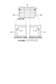
- FIG. 5 is a diagram showing an example of the configuration of the ATC provided in the die-sinking electric discharge machine according to embodiment 1.
- Fig. 6 is a schematic diagram showing how the imaging device and the machining electrode are replaced by the ATC provided in the die-sinking electric discharge machine according to embodiment 1.
- the ATC 9 has a magazine 9a, a rotating shaft 9b, a support 9c, and a guide 9d.
- the magazine 9a stores the unused machining electrodes 5 and the imaging device 3.
- the magazine 9a stores the machining electrodes 5 and the imaging device 3 in a suspended manner.
- the rotating shaft 9b connects the magazine 9a to the support 9c.
- the rotating shaft 9b can rotate in the direction indicated by the arrow C.
- the central axis of the rotating shaft 9b extends, for example, in the vertical or perpendicular direction.
- the direction indicated by the arrow C is a circumferential direction centered on the position of the central axis of the rotating shaft 9b.
- the magazine 9a In synchronization with the rotation of the rotating shaft 9b in the direction of the arrow C, the magazine 9a also rotates in the direction of the arrow C.
- the support 9c supports the magazine 9a via the rotating shaft 9b.
- the support 9c is guided by the guide 9d and can move in the direction of the arrow D.
- the guide 9d is a rod-shaped member extending in the direction of the arrow D.
- the machining electrode 5 is attached to the spindle 1 of the die-sinking electric discharge machine 100 via the electrode chuck 2.
- the machining electrode 5 can be automatically attached and detached to the electrode chuck 2 by programmed operation of the NC device 72.
- the machining electrode 5 removed from the spindle 1 of the die-sinking electric discharge machine 100 is returned to the magazine 9a of the ATC 9.
- the imaging device 3 can also be automatically attached and detached to the spindle 1 of the die-sinking electric discharge machine 100.
- Fig. 6(a) shows the imaging device 3 attached to the spindle 1
- Fig. 6(b) shows the machining electrode 5 attached to the spindle 1.
- the imaging device 3 is connected to the spindle 1 via a connector.
- the connector connection is established by connecting the first connector terminal 12 and the second connector terminal 13.
- no cables or the like are used to connect the imaging device 3 to the spindle 1.
- the camera of the conventional machining device of Patent Document 1 and the like is connected to a recognition device or a calculation device by a wired cable. If the camera of the conventional machining device of Patent Document 1 and the like were made to be automatically attached and detached by the ATC 9, problems would arise when the camera is moved in and out of the magazine of the ATC 9, such as the camera cable becoming entangled with the spindle 1, becoming immersed in the machining fluid, or becoming disconnected.
- the imaging device 3 is connected to the spindle 1 via a connector, so problems caused by such cables do not occur.
- the connector connection is explained below.
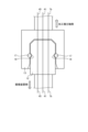
- FIG. 7 is a diagram showing an example of a connector connection configuration provided in the die-sinking electric discharge machine according to the first embodiment.
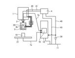
- Fig. 16 is a diagram showing a wiring configuration when an imaging device and a control box are attached to the die-sinking electric discharge machine according to the first embodiment. In Fig. 16, some wiring unnecessary for the description is omitted in order to make the description easier to understand.
- the imaging device 3 is provided with a first connector terminal 12, and the spindle 1 is provided with a second connector terminal 13.
- the first connector terminal 12 is a male type
- the second connector terminal 13 is a female type.
- the first connector terminal 12 By inserting the first connector terminal 12 into a recess of the female second connector terminal 13, the first connector terminal 12 and the second connector terminal 13 are electrically connected to each other, and a connector connection is established.
- the first connector terminal 12 may be a female type
- the second connector terminal 13 may be a male type.
- the second contact detection line 7b, the power supply line 41, and the signal line 45 run inside the first connector terminal 12 and the second connector terminal 13.
- the second contact detection line 7b connects the imaging device cover 6 and the contact detection unit 70.
- the power supply line 41 supplies power from the power supply 30 to the imaging device 3 via the control box 4.
- the signal line 45 transmits imaging data obtained by the imaging device 3 to the control box 4.
- the imaging device 3 and the control box 4 are connected by a connector so that the wired connection between them is automatically established.
- the imaging device 3 is attached to the electrode chuck 2 provided on the spindle 1 by program operation under the control of the NC device 72, and the connector connection is also automatically performed at the same time. Therefore, the user's workload can be reduced when replacing the machining electrode 5 and the imaging device 3.
- the connector connection is performed automatically, for example, the first connector terminal 12 is supported by a member having high rigidity. As shown in FIG. 1, the member is provided between the first connector terminal 12 and the imaging device 3, and is a member that holds the first connector terminal 12, and has, for example, an L-shape in a plan view.
- the recess 18 functions as a roller bearing for the roller 17.
- the roller 17 abuts against the inner wall of the recess 18 and gets caught, preventing the first connector terminal 12 from falling off the second connector terminal 13.
- a spring 19 is connected to the roller 17.
- One end of the spring 19 is joined to the roller 17, and the other end of the spring 19 is joined to the second connector terminal 13.
- the spring 19 is not contracted, and a part of the roller 17 protrudes from the inner wall of the second connector terminal 13 toward the space inside the second connector terminal 13.
- the imaging device 3 is attached to the spindle 1 via the electrode chuck 2
- the roller 17 is pressed by the insertion pressure of the first connector terminal 12, and the spring 19 contracts.
- the entire roller 17 is completely contained within the second connector terminal 13. This makes it possible to insert the first connector terminal 12 into the second connector terminal 13.
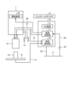
- Fig. 9 is a diagram showing the configuration of a contact detection function in the die-sinking electric discharge machine according to embodiment 1.
- Fig. 9 shows a contact detection circuit that detects contact between the image capture device cover 6 of the image capture device 3 and the workpiece 16.
- the imaging device 3 In order for the imaging device 3 to obtain an image with sub-micron-order accuracy, the imaging device 3 must be brought close to the workpiece 16.
- existing conventional die-sinking electric discharge machines are provided with a contact detection function that detects contact between the machining electrode 5 and the workpiece 16.
- existing conventional die-sinking electric discharge machines are not provided with a contact detection function that detects contact between the imaging device 3 and the workpiece 16. As a result, there have been actual cases where both the imaging device 3 and the workpiece 16 have been damaged when the imaging device 3 and the workpiece 16 come into contact.
- the contact detection circuit 7 between the machining electrode 5 and the workpiece 16, which is unique to the die-sinking electric discharge machine 100, is also applied to the imaging device 3.
- an imaging device cover 6 that can be electrically connected is attached to the imaging device 3.
- the contact detection unit 70 detects contact between the workpiece 16 and the imaging device cover 6 by detecting that a current has flowed through the electrical circuit.
- the operation when the machining electrode 5 and the workpiece 16 come into contact is similar. That is, when the workpiece 16 and the machining electrode 5 come into contact, one electrical circuit is formed by the machining electrode 5, the workpiece 16, the surface plate 21, the first contact detection line 7a, the contact detection unit 70, and the second contact detection line 7b.
- the contact detection unit 70 detects contact between the workpiece 16 and the machining electrode 5 by detecting that a current has flowed through the electrical circuit.
- the contact detection unit 70 detects contact, it instantly outputs a contact detection signal to the NC device 72.
- the NC device 72 receives the contact detection signal, it outputs a command from the spindle control unit 72a to the drive device 50 that drives the spindle 1 to make an emergency stop of the operation of the spindle 1.
- a contact detection circuit 7 composed of the first contact detection line 7a and the second contact detection line 7b is provided, so that it is possible to detect not only contact between the machining electrode 5 and the workpiece 16, but also contact between the imaging device 3 and the workpiece 16.
- the contact detection unit 70 in the power supply panel 10 immediately detects the contact and can bring about an emergency stop of the spindle 1 via the NC device 72. This makes it possible to minimize damage to the imaging device 3 and the workpiece 16.
- the imaging device cover 6 and the contact detection unit 70 need to be connected by wire, similar to the imaging device 3. It is desirable that the wired connection between the imaging device cover 6 and the contact detection unit 70 can be automatically attached and detached by program operation. Therefore, in the first embodiment, as described above, the imaging device cover 6 and the contact detection unit 70 are connected by wire using the connector connection shown in FIG.
- Fig. 10 is a diagram showing the configuration of an insulating function in the die-sinking electric discharge machine according to embodiment 1.
- Fig. 10 shows an insulating function that provides insulation between the contact detection unit 70 in the power supply panel 10 of the die-sinking electric discharge machine 100 and the control box 4.
- the insulating function is provided to prevent the spindle 1 from always coming to a stop due to an erroneous detection that the imaging device 3 and the workpiece 16 are in contact when the imaging device 3 is attached to the spindle 1.
- an earth 20 is provided in the imaging device 3 at a location that is not in contact with the housing, and the electrical part 3b of the imaging device 3 is connected to the earth 20.
- the earth 20 is not in electrical contact with the housing of the imaging device 3 or the imaging device cover 6.
- the earth 20 is sometimes called an insulating section. This makes it possible to prevent the contact detection unit 70 from erroneously detecting that the workpiece 16 and the imaging device 3 are in contact when the imaging device 3 is attached to the spindle 1 in the first embodiment.
- the power supply unit 4a, the image processing unit 4b, and the calculation unit 4d are realized by a processing circuit.
- the processing circuit may be a processor and memory that executes a program stored in a memory, or may be dedicated hardware.
- the processing circuit is also called a control circuit.
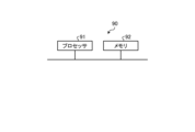
- FIG. 11 is a diagram showing an example of the configuration of a processing circuit when the processing circuit provided in the control box according to the first embodiment is realized by a processor and a memory.
- the processing circuit 90 shown in FIG. 11 is a control circuit and includes a processor 91 and a memory 92.
- each function of the processing circuit 90 is realized by software, firmware, or a combination of software and firmware.
- the software or firmware is written as a program and stored in the memory 92.
- each function is realized by the processor 91 reading and executing the program stored in the memory 92. That is, the processing circuit 90 includes a memory 92 for storing a program that will result in the processing of the control box 4 being executed.
- This program can also be said to be a program that causes the control box 4 to execute each function realized by the processing circuit 90.
- This program may be provided by a storage medium in which the program is stored, or by other means such as a communication medium.
- the above program can also be said to be a program that causes the control box 4 to execute the processes of steps S2, S4, and S5 in FIG. 4, for example.
- the above program can also be said to be a program that causes the control box 4 to execute a step of storing a first coordinate, a step of storing a second coordinate, and a step of calculating the distance between the first measurement point A and the second measurement point B based on the first coordinate and the second coordinate.
- the processor 91 is, for example, a CPU (Central Processing Unit), a processing device, an arithmetic unit, a microprocessor, a microcomputer, or a DSP (Digital Signal Processor).
- the memory 92 is, for example, a non-volatile or volatile semiconductor memory such as a RAM (Random Access Memory), a ROM (Read Only Memory), a flash memory, an EPROM (Erasable Programmable ROM), an EEPROM (registered trademark) (Electrically EPROM), a magnetic disk, a flexible disk, an optical disk, a compact disk, a mini disk, or a DVD (Digital Versatile Disc).
- FIG. 12 is a diagram showing an example of a processing circuit provided in the control box according to embodiment 1 when the processing circuit is configured with dedicated hardware.
- the processing circuit 93 shown in FIG. 12 corresponds to, for example, a single circuit, a composite circuit, a programmed processor, a parallel programmed processor, an ASIC (Application Specific Integrated Circuit), an FPGA (Field Programmable Gate Array), or a combination of these.
- the processing circuit 93 may be partially realized with dedicated hardware and partially realized with software or firmware. In this way, the processing circuit 93 can realize each of the above-mentioned functions by dedicated hardware, software, firmware, or a combination of these.
- the PC 8 is also configured with the processing circuit 90 shown in FIG. 11 or the processing circuit 93 shown in FIG. 12.
- the spindle control unit 72a, the ATC control unit 72b, and the machining control unit 72c of the NC device 72 are also configured with, for example, the processing circuit 90 shown in FIG. 11 or the processing circuit 93 shown in FIG. 12.
- the processing circuits 90 and 93 in these cases have the same configuration as those in the control box 4, so their description will be omitted here.
- the imaging device 3 that can be attached to the spindle 1 since the imaging device 3 that can be attached to the spindle 1 is provided, the surface shape and dimensions of the workpiece 16 after processing can be confirmed without removing the workpiece 16 from the surface plate 21. Therefore, even if the confirmation result indicates that additional processing is required for the workpiece 16, the time and effort required to place the workpiece 16 on the surface plate 21 again can be reduced. In addition, the occurrence of minute positional deviations due to the workpiece 16 being placed again can be prevented. Furthermore, since the imaging device 3 is attached to the spindle 1, the imaging device 3 can be moved together with the spindle 1. Therefore, it is possible to photograph the workpiece 16 in a desired range, from a wide range to a narrow range, and the focus adjustment range of the imaging device 3 can be widened.
- the earth 20 is provided in the imaging device 3 at a location that does not contact the housing of the imaging device 3 and the imaging device cover 6.
- the control box 4 and the contact detection unit 70 in the power supply panel 10 are insulated from each other by connecting the electric part 3b of the imaging device 3 to the earth 20, which is different from the earth 11. Therefore, when the imaging device 3 is attached to the spindle 1, it is possible to prevent the imaging device 3, the control box 4, the contact detection unit 70, and the spindle 1 from forming a single electric circuit. As a result, it is possible to prevent the contact detection unit 70 from erroneously detecting that the workpiece 16 and the imaging device 3 are in contact when the imaging device 3 is attached to the spindle 1.
- the imaging device 3 can be freely moved together with the spindle 1.
- the machining electrode 5 and the imaging device 3 can be automatically attached and detached to the spindle 1.
- the removed machining electrode 5 and imaging device 3 are stored in the magazine 9a of the ATC 9. Because the magazine 9a is installed away from the machining tank, it is possible to prevent the machining electrode 5 and imaging device 3 stored in the magazine 9a from being exposed to oily smoke generated from the machining fluid. As a result, it is possible to prevent the lens 3a of the imaging device 3 from being soiled by oily smoke, and the internal circuit board of the electrical section 3b of the imaging device 3 from being deteriorated by oily smoke.
- the imaging device 3 and the control box 4 are connected, and the imaging device cover 6 and the contact detection unit 70 are connected by a connector connection consisting of a first connector terminal 12 and a second connector terminal 13.
- the imaging device 3 and the control box 4, or the imaging device cover 6 and the contact detection unit 70 are connected by a wired connection using a cable or the like.
- the cable may get caught or tangled on the spindle 1 or the ATC 9, and the cable may be pulled and broken. Furthermore, the cable may become immersed in the machining fluid.
- these problems caused by the cable do not occur.
- the control box 4 can acquire the coordinates of the first measurement point A and the second measurement point B on the workpiece 16. This allows the dimensions of each part of the workpiece 16 to be easily measured.
- the user can use the PC 8 to check the image data 15 of the workpiece 16 in real time, allowing them to inspect whether the shape and dimensions of the workpiece 16 are accurate and correct.
- the camera does not have an emergency stop function in the event of contact, so there is a possibility that the camera or the workpiece may be damaged if the camera continues to come into contact with the workpiece.
- Even if the camera is equipped with an emergency stop function in case of contact if the ground of the internal circuit board of the camera is connected to the camera housing, the moment the camera is attached to the spindle, the spindle will enter an emergency stop state. As a result, the spindle will be fixed and the camera cannot be moved, making it impossible to photograph the workpiece in the desired range, and the focus adjustment range of the camera will be narrowed.
- the die-sinking electric discharge machine 100 according to the first embodiment can solve all of these problems (1) to (5) as described above.
Landscapes
- Engineering & Computer Science (AREA)
- Mechanical Engineering (AREA)
- Chemical & Material Sciences (AREA)
- Chemical Kinetics & Catalysis (AREA)
- Electrochemistry (AREA)
- Electrical Discharge Machining, Electrochemical Machining, And Combined Machining (AREA)
Priority Applications (3)
| Application Number | Priority Date | Filing Date | Title |
|---|---|---|---|
| CN202380073903.XA CN120076894B (zh) | 2023-06-07 | 2023-06-07 | 雕模放电加工机 |
| JP2023565634A JP7442753B1 (ja) | 2023-06-07 | 2023-06-07 | 形彫放電加工機 |
| PCT/JP2023/021244 WO2024252592A1 (ja) | 2023-06-07 | 2023-06-07 | 形彫放電加工機 |
Applications Claiming Priority (1)
| Application Number | Priority Date | Filing Date | Title |
|---|---|---|---|
| PCT/JP2023/021244 WO2024252592A1 (ja) | 2023-06-07 | 2023-06-07 | 形彫放電加工機 |
Publications (1)
| Publication Number | Publication Date |
|---|---|
| WO2024252592A1 true WO2024252592A1 (ja) | 2024-12-12 |
Family
ID=90096848
Family Applications (1)
| Application Number | Title | Priority Date | Filing Date |
|---|---|---|---|
| PCT/JP2023/021244 Ceased WO2024252592A1 (ja) | 2023-06-07 | 2023-06-07 | 形彫放電加工機 |
Country Status (3)
| Country | Link |
|---|---|
| JP (1) | JP7442753B1 (enExample) |
| CN (1) | CN120076894B (enExample) |
| WO (1) | WO2024252592A1 (enExample) |
Families Citing this family (1)
| Publication number | Priority date | Publication date | Assignee | Title |
|---|---|---|---|---|
| CN118848136B (zh) * | 2024-09-20 | 2025-01-14 | 国营川西机器厂 | 涡轮叶片叶尖电火花成型的自适应定位方法 |
Citations (3)
| Publication number | Priority date | Publication date | Assignee | Title |
|---|---|---|---|---|
| JP2001147115A (ja) * | 1999-11-22 | 2001-05-29 | Mitsutoyo Corp | 測定機の衝突防止装置 |
| US20180147645A1 (en) * | 2016-11-26 | 2018-05-31 | Agie Charmilles Sa | Method for machining and inspecting of workpieces |
| WO2022181441A1 (ja) * | 2021-02-26 | 2022-09-01 | Dmg森精機株式会社 | 工作機械および工作機械に着脱可能な工作機械用装置 |
Family Cites Families (6)
| Publication number | Priority date | Publication date | Assignee | Title |
|---|---|---|---|---|
| JP2876032B2 (ja) * | 1989-07-17 | 1999-03-31 | 株式会社ソディック | 放電加工装置 |
| JP3222178B2 (ja) * | 1991-07-23 | 2001-10-22 | 三菱電機株式会社 | 放電加工機および放電加工装置 |
| JP3515023B2 (ja) * | 1999-08-25 | 2004-04-05 | 太 森山 | 測定方法および測定装置 |
| JP5205996B2 (ja) * | 2008-02-04 | 2013-06-05 | 株式会社デンソー | 放電加工方法 |
| JP6321703B2 (ja) * | 2016-03-04 | 2018-05-09 | ファナック株式会社 | ワイヤ放電加工機の検査システム |
| JP7343328B2 (ja) * | 2019-08-02 | 2023-09-12 | ファナック株式会社 | ワイヤ放電加工機および制御方法 |
-
2023
- 2023-06-07 CN CN202380073903.XA patent/CN120076894B/zh active Active
- 2023-06-07 WO PCT/JP2023/021244 patent/WO2024252592A1/ja not_active Ceased
- 2023-06-07 JP JP2023565634A patent/JP7442753B1/ja active Active
Patent Citations (3)
| Publication number | Priority date | Publication date | Assignee | Title |
|---|---|---|---|---|
| JP2001147115A (ja) * | 1999-11-22 | 2001-05-29 | Mitsutoyo Corp | 測定機の衝突防止装置 |
| US20180147645A1 (en) * | 2016-11-26 | 2018-05-31 | Agie Charmilles Sa | Method for machining and inspecting of workpieces |
| WO2022181441A1 (ja) * | 2021-02-26 | 2022-09-01 | Dmg森精機株式会社 | 工作機械および工作機械に着脱可能な工作機械用装置 |
Also Published As
| Publication number | Publication date |
|---|---|
| CN120076894A (zh) | 2025-05-30 |
| JPWO2024252592A1 (enExample) | 2024-12-12 |
| JP7442753B1 (ja) | 2024-03-04 |
| CN120076894B (zh) | 2025-12-02 |
Similar Documents
| Publication | Publication Date | Title |
|---|---|---|
| JP7008044B2 (ja) | 座標測定機のための取り外し可能なプローブに電力を供給するための電力伝達構成体 | |
| US8381588B2 (en) | Storage apparatus for a measurement probe | |
| KR102105156B1 (ko) | 가공 데이터 생성 방법 및 피복 용접 방법 | |
| US5248867A (en) | Electric spark machine | |
| WO2024252592A1 (ja) | 形彫放電加工機 | |
| US20160098837A1 (en) | Substrate Inspection Apparatus and Control Method Thereof | |
| TWI738876B (zh) | 在製造操作中使用於定位管狀部件位置之系統、方法及裝置 | |
| JP7017534B2 (ja) | 工作機械、加工システム、およびプルスタッドの適否判定方法 | |
| CN107206563A (zh) | 用于确定工件在机床中的位置的方法 | |
| US20090233459A1 (en) | Wiring board and optical disk drive using the same | |
| CN112233971B (zh) | 一种晶圆清洗方法和晶圆清洗装置 | |
| JP6829062B2 (ja) | 三次元測定装置 | |
| CN104457568A (zh) | 用于恶劣环境中的无线视觉系统和方法 | |
| CN112387992A (zh) | 机床系统 | |
| JP6210591B2 (ja) | マシニングセンタ、接触検知装置、及び、接触検出用センサプローブ | |
| CN113246219A (zh) | 气夹装置、销钉定位系统、钻孔机及加工精度补偿方法 | |
| JP2009037244A (ja) | 光ファイバのスプライス接続装置 | |
| CN111751690A (zh) | 一种耐压测试设备 | |
| JPWO2024252592A5 (enExample) | ||
| KR102082072B1 (ko) | 배관-관판 용접 시스템의 u자관 축 방향 이동 검출 장치 및 방법 | |
| JPWO2019102890A1 (ja) | 基板検査装置、検査位置補正方法、位置補正情報生成方法、及び位置補正情報生成システム | |
| EP1074328A2 (en) | Method and apparatus for machining a workpiece using electric discharge machining | |
| JP7168831B2 (ja) | 研削及び/又は侵食機械、ならびに機械の測定及び/又は基準化方法 | |
| CN111932558A (zh) | 高温危险区域定位方法 | |
| JP2007095938A (ja) | テスタ、プローバ、ウエハテストシステム及び電気的接触位置検出方法 |
Legal Events
| Date | Code | Title | Description |
|---|---|---|---|
| WWE | Wipo information: entry into national phase |
Ref document number: 2023565634 Country of ref document: JP |
|
| 121 | Ep: the epo has been informed by wipo that ep was designated in this application |
Ref document number: 23940693 Country of ref document: EP Kind code of ref document: A1 |
|
| WWE | Wipo information: entry into national phase |
Ref document number: 202380073903.X Country of ref document: CN |
|
| WWP | Wipo information: published in national office |
Ref document number: 202380073903.X Country of ref document: CN |
|
| NENP | Non-entry into the national phase |
Ref country code: DE |