WO2024252547A1 - ロボット管理装置、ロボット管理方法、ロボット管理プログラムおよび記録媒体 - Google Patents
ロボット管理装置、ロボット管理方法、ロボット管理プログラムおよび記録媒体 Download PDFInfo
- Publication number
- WO2024252547A1 WO2024252547A1 PCT/JP2023/021114 JP2023021114W WO2024252547A1 WO 2024252547 A1 WO2024252547 A1 WO 2024252547A1 JP 2023021114 W JP2023021114 W JP 2023021114W WO 2024252547 A1 WO2024252547 A1 WO 2024252547A1
- Authority
- WO
- WIPO (PCT)
- Prior art keywords
- robot
- task
- energy
- energy consumption
- subtasks
- Prior art date
- Legal status (The legal status is an assumption and is not a legal conclusion. Google has not performed a legal analysis and makes no representation as to the accuracy of the status listed.)
- Ceased
Links
Images



Definitions
- This invention relates to a technology that determines whether a robot can execute a task based on the robot's remaining battery power.
- Patent Document 1 shows a technique for calculating the amount of discharge per round of a drive battery mounted on an electric golf cart that repeatedly travels around a specified course.
- Patent Document 2 shows a technique for setting an execution plan for each robot for the tasks to be performed according to the remaining power of the robot's battery.
- This invention has been made in consideration of the above problems, and aims to make it possible to estimate with high accuracy the energy consumed by a robot to execute a task, and to appropriately assign tasks to the robot.
- the robot management device includes a subtask identification unit that identifies multiple subtasks included in a task to be executed by a robot that operates using energy stored in a battery; an energy consumption estimation unit that calculates the energy required to execute the subtask for each of the multiple subtasks and estimates the energy consumed by the robot to execute the task as an estimated energy consumption based on the total energy calculated for each of the multiple subtasks; and an execution feasibility determination unit that determines whether the task can be executed by the robot based on the remaining energy in the battery and the estimated energy consumption.
- the robot management method includes a step of identifying a number of subtasks included in a task to be executed by a robot that operates using energy stored in a battery, a step of calculating the energy required to execute the subtask for each of the subtasks, and estimating the energy consumed by the robot to execute the task as an estimated energy consumption based on the total energy calculated for each of the subtasks, and a step of determining whether the robot can execute the task based on the remaining energy in the battery and the estimated energy consumption.
- the robot management program according to the present invention causes a computer to execute the robot management method described above.
- the recording medium records the robot management program in a computer-readable manner.
- robot management device robot management method, robot management program, and recording medium
- multiple subtasks included in a task to be executed by the robot are identified, and the energy required to execute the subtasks is calculated for each of the multiple subtasks.
- the energy consumed by the robot to execute the task is estimated as the estimated energy consumption.
- This makes it possible to estimate with high accuracy the energy consumed by the robot to execute the task as the estimated energy consumption.
- it is determined whether the robot can execute the task As a result, it becomes possible to estimate with high accuracy the energy consumed by the robot to execute the task, and appropriately assign tasks to robots.
- the robot management device may also be configured so that the energy consumption estimation unit calculates, for each of a number of subtasks, the energy required to execute a unit operation included in the subtask based on information that associates unit operations that the robot can execute with the energy consumed by the robot to execute the unit operation, and estimates the energy consumed by the robot to execute the task as the estimated energy consumption based on the total energy calculated for each of the multiple subtasks.
- the energy required to execute a subtask can be calculated simply and accurately based on the energy required to execute a unit operation. As a result, it is possible to accurately estimate the energy consumed by the robot to execute a task, and appropriately assign tasks to the robot.
- the robot management device may also be configured so that the energy consumption estimation unit estimates the estimated energy consumption by adjusting the total energy calculated for each of the multiple subtasks according to the surrounding environment of the robot performing the task.
- the energy consumed by the robot to perform the task can be estimated with high accuracy according to the surrounding environment of the robot.
- the robot management device may also be configured so that the energy consumption estimation unit estimates the estimated energy consumption by adjusting the total energy calculated for each of the multiple subtasks using ambient environment parameters that correspond to the ambient environment of the robot performing the task.
- the energy consumption estimation unit estimates the estimated energy consumption by adjusting the total energy calculated for each of the multiple subtasks using ambient environment parameters that correspond to the ambient environment of the robot performing the task.
- the robot management device may also be configured so that the energy consumption estimation unit corrects the surrounding environment parameters based on the energy actually consumed by the robot when executing a task.
- the surrounding environment parameters can be optimized based on the energy actually consumed by the robot when executing a task. As a result, it is possible to estimate with higher accuracy the energy consumed by the robot to execute a task thereafter.
- the robot management device may also be configured so that the energy consumption estimation unit estimates the estimated energy consumption by adjusting the total energy calculated for each of the multiple subtasks according to conditions specific to the robot that executes the task.
- the energy consumed by the robot to execute a task can be estimated with high accuracy according to conditions specific to the robot.
- the robot management device may also be configured so that the energy consumption estimation unit estimates the estimated energy consumption by adjusting the total energy calculated for each of the multiple subtasks using specific condition parameters according to conditions specific to the robot executing the task.
- the energy consumption estimation unit estimates the estimated energy consumption by adjusting the total energy calculated for each of the multiple subtasks using specific condition parameters according to conditions specific to the robot executing the task.
- the robot management device may also be configured so that the energy consumption estimation unit corrects the inherent condition parameters based on the energy actually consumed by the robot when executing a task.
- the inherent condition parameters can be optimized based on the energy actually consumed by the robot when executing a task. As a result, it is possible to estimate with higher accuracy the energy consumed by the robot to execute a task thereafter.
- the robot management device may be configured to further include a robot monitoring unit that monitors the state of the robot based on the values of the inherent condition parameters. With such a configuration, the state of the robot can be accurately grasped.
- the robot management device may also be configured so that the robot monitoring unit notifies the robot to perform maintenance if it determines that an abnormality has occurred in the robot as a result of monitoring the robot's status. With this configuration, it becomes possible to perform maintenance on the robot at an appropriate time.
- FIG. 1 is a diagram showing an example of a board production system including an FMS controller corresponding to a robot management device according to the present invention.
- 2 is a block diagram showing an example of an electrical configuration of an automatic guided vehicle that executes a predetermined task in the board production system of FIG. 1 .
- FIG. 2 is a block diagram showing an example of an electrical configuration of an FMS controller provided in the board production system of FIG. 1 .
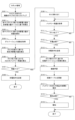
- 11 is a flowchart showing an example of robot management.
- FIG. 2 is a diagram illustrating an example of a task.
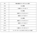
- FIG. 10 is a diagram illustrating an example of subtasks listed based on a task.
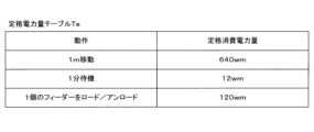
- FIG. 4 is a diagram illustrating an example of a rated power table.
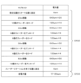
- FIG. 4 is a diagram showing an example of a calculation based on a rated power table;
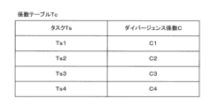
- FIG. 4 is a diagram illustrating an example of a coefficient table.
- FIG. 1 shows a flexible management system (FMS) corresponding to a robot management device according to the present invention.
- FMS flexible management system
- 2A is a block diagram showing an example of the electrical configuration of an automatic guided vehicle that executes a predetermined task in the board production system of FIG. 1
- FIG. 2B is a block diagram showing an example of the electrical configuration of an FMS controller provided in the board production system of FIG. 1.
- board production system 1 produces boards on which electronic components are mounted.
- board production system 1 includes component mounters 2A-2D, feeder stations 3A-3B, an automated guided vehicle 4 (robot), charging stations 5A-5D, and an FMS controller 9.
- Each of the component mounters 2A to 2D mounts electronic components on a board by transferring the electronic components supplied by a feeder such as a tape feeder or tray feeder to the board using a suction nozzle.
- the feeders are removably attached to predetermined locations of the component mounters 2A to 2D and are replaced as appropriate depending on the type of board being produced.
- Each of the feeder stations 3A to 3B is provided separately from the component mounters 2A to 2D in order to store the feeders.
- the unmanned guided vehicle 4 includes a vehicle body 41 and a plurality of wheels 42 that drive the vehicle body 41, and the unmanned guided vehicle 4 moves when the wheels 42 rotate.
- the specific configuration for driving the vehicle body 41 is not limited to the wheels 42, and may be, for example, a caterpillar track.
- the unmanned guided vehicle 4 also includes a travel motor 431 that drives the wheels 42 and a steering wheel 432 that changes the direction of the wheels 42. In other words, the travel motor 431 drives the wheels 42, causing the wheels 42 to rotate and the unmanned guided vehicle 4 to move.
- the steering wheel 432 changes the direction of the wheels 42, changing the direction in which the unmanned guided vehicle 4 moves.
- the unmanned guided vehicle 4 also includes a robot arm 433 (FIG. 2A) that can grab and transfer the work object. In this way, the travel motor 431, the steering wheel 432, and the robot arm 433 constitute the operating unit 43 that performs a predetermined operation.
- the automated guided vehicle 4 is equipped with a battery 44 that stores electrical energy, and the operating unit 43 performs operations using electrical energy supplied from the battery 44. Therefore, as energy is consumed by the automated guided vehicle 4 performing its operations, the amount of electrical energy stored in the battery 44 (remaining battery capacity) decreases.
- the automated guided vehicle 4 is equipped with a communication unit 45 that performs wireless communication with the FMS controller 9, and a calculation unit 49 that controls the operation unit 43, the battery 44, and the communication unit 45.
- the calculation unit 49 is, for example, a processor, and controls the operation unit 43 to execute tasks indicated by commands received by the communication unit 45 from the FMS controller 9. This allows the automated guided vehicle 4 to execute various tasks, such as transporting feeders between the feeder stations 3A-3B and the component mounters 2A-2C, and transporting boards before electronic components are mounted on them, and boards after electronic components have been mounted on them.
- the charging stations 5A to 5D ( Figure 1) are provided to charge the battery 44 installed on the automated guided vehicle 4.
- the automated guided vehicle 4 moves to one of the charging stations 5A to 5D and docks with that one charging station 5. That one charging station 5 charges the battery 44 of that automated guided vehicle 4.
- the FMS controller 9 includes a calculation unit 91, a memory unit 95, a UI (User Interface) 96, and a communication unit 97.
- the calculation unit 91 is, for example, a processor, and executes a robot management program P to construct a task setting unit 92, a dynamic task allocation unit 93, and a robot monitoring unit 94.
- the dynamic task allocation unit 93 has a subtask identification unit 931, an energy consumption estimation unit 932, and an allocation determination unit 933. Details of the task setting unit 92, dynamic task allocation unit 93, and robot monitoring unit 94 will be described later in conjunction with the robot management in FIG. 3.
- the storage unit 95 is, for example, a solid state drive (SSD).
- the UI 96 is a storage device such as a USB flash drive, and stores a robot management program P, a rated power table Te, a coefficient table Tc, and a task execution log Lt used in the robot management of FIG. 3.
- the UI 96 has input devices such as a keyboard and a mouse, and output devices such as a display and a speaker, and a user operates the input devices to input to the FMS controller 9, and recognizes notifications from the FMS controller 9 by checking the output devices. It is not necessary to configure the input devices and output devices of the UI 96 separately, and they may be configured integrally using a touch panel display or the like.
- the communication unit 97 wirelessly communicates with the communication unit 45 of the automatic guided vehicle 4.
- FIG. 3 is a flowchart showing an example of robot management.
- the flowchart in FIG. 3 is executed by the FMS controller 9 (FIG. 2B). Specifically, the flowchart in FIG. 3 is started when a task to be executed by the automated guided vehicle 4 is set by the task setting unit 92.
- the task setting unit 92 sets the task based on a program that specifies the execution of the task or on input by the user to the UI 96.
- step S101 the subtask identification unit 931 lists a number of subtasks that the automated guided vehicle 4 should execute in order to execute the task set by the task setting unit 92. This will be explained in detail using Figures 4A and 4B.
- Fig. 4A is a diagram showing an example of a task.
- a task Ts1 is set by the task setting unit 92.
- This task Ts1 is composed of the following steps: move to feeder station 3A, take out 10 feeders from feeder station 3A, move to component mounter 2A, attach 6 feeders to component mounter 2A, remove 6 feeders from component mounter 2A, move to component mounter 2B, attach 4 feeders to component mounter 2B, remove 4 feeders from component mounter 2B, move to feeder station 3A, and put 10 feeders into feeder station 3A.
- FIG. 4B is a diagram showing an example of subtasks listed based on a task.
- a plurality of subtasks ST1 to ST12 are listed by the subtask identifying unit 931.
- ST1 Set the current position of the automated guided vehicle 4 to the start position.
- ST2 Move the automated guided vehicle 4 20 meters.
- ST3 Load 10 feeders onto the automated guided vehicle 4.
- ST4 Move the automated guided vehicle 4 40 meters.
- ST5 Unload 6 feeders onto the automated guided vehicle 4.
- ST6 Load 6 feeders onto the automated guided vehicle 4.
- ST7 Move the automated guided vehicle 4 30 meters.
- ST8 Unload 4 feeders onto the automated guided vehicle 4.
- ST10 Mobility the automated guided vehicle 4 50 meters.
- ST11 Unload ten feeders onto the automated guided vehicle 4.
- ST12 ...Set feeder station 3A to the end position of the automated guided vehicle 4.
- load refers to the operation of the robot arm 433 transferring a feeder from another device to the automated guided vehicle 4
- unload refers to the operation of the robot arm 433 transferring a feeder from the automated guided vehicle 4 to another device.
- the energy consumption estimation unit 932 calculates the estimated power consumption by estimating the power consumption required to execute the task Ts1 based on the subtasks ST1 to ST12 identified in step S101 (steps S102 to S105). In particular, the calculation of the estimated power consumption is performed based on the rated power table Te ( Figure 4C).
- FIG. 4C is a diagram showing an example of a rated power table
- FIG. 4D is a diagram showing an example of a calculation based on the rated power table.
- the energy consumption estimation unit 932 calculates the amount of power required to execute each of the subtasks ST1 to ST12 based on the rated power table Te (FIG. 4C).
- the rated power table Te As shown in FIG. 4C, in the rated power table Te, unit operations that can be executed by the automated guided vehicle 4 (moving one meter, waiting one minute, loading/unloading one feeder) and the amount of power consumption (rated power consumption) required for the automated guided vehicle 4 to execute the unit operation are associated with each of a plurality of operations.
- This rated power table Te is created and provided in advance by the manufacturer of the automated guided vehicle 4.
- the energy consumption estimation unit 932 refers to the rated power table Te to calculate the amount of power consumption required to execute all unit operations included in the subtask, thereby calculating the amount of power consumption required to execute the subtask.
- the energy consumption estimation unit 932 performs this calculation of the power consumption amount for each of the subtasks ST1 to ST12 (step S102 in FIG. 4D).
- step S103 the energy consumption estimation unit 932 calculates the total amount of power consumption (total electric power amount) of the multiple subtasks by adding up the amount of power consumption calculated for each of the multiple subtasks ST1 to ST12 (step S103 in FIG. 4D).
- step S104 the energy consumption estimation unit 932 obtains a divergence coefficient from the coefficient table Tc (FIG. 4E).
- FIG. 4E is a diagram showing an example of a coefficient table.
- the coefficient table Tc shows the task Ts and the divergence coefficient C corresponding to the task Ts for each of a number of tasks Ts1 to Ts4.
- the divergence coefficient C is a coefficient for correcting the discrepancy between the amount of power consumed in the actual operation of the automated guided vehicle 4 and the amount of power shown in the rated power table Te.
- This coefficient table Tc is provided for each automated guided vehicle 4, and the coefficient table Tc differs for each individual automated guided vehicle 4.
- the energy consumption estimation unit 932 obtains the divergence coefficient C1 associated with the target task Ts1 by the coefficient table Tc.
- step S106 the allocation determination unit 933 estimates the remaining charge of the battery 44 of the automated guided vehicle 4 when the task Ts1 is completed by subtracting the estimated power consumption from the current remaining charge of the battery 44 of the automated guided vehicle 4.
- the allocation determination unit 933 compares the estimated remaining charge of the battery 44 (estimated battery remaining charge) with the allocation reference threshold to determine whether the estimated battery remaining charge is sufficient (step S107).
- the allocation determination unit 933 sets the allocation reference threshold to the amount of power required for the automated guided vehicle 4 to move from the position (end position) of the automated guided vehicle 4 at the time of completing the task Ts1 to the charging station 5 farthest from the end position.
- the allocation determination unit 933 determines that the estimated battery remaining charge is insufficient ("NO" in step S107) and transmits a charging command from the communication unit 97 to the automated guided vehicle 4 that is the subject of robot management (FIG. 3) (step S108).
- the automated guided vehicle 4 receives a charging command, it moves to one of the charging stations 5A to 5D and charges the battery 44.
- the robot management in FIG. 3 is also performed for another automated guided vehicle 4.
- the allocation determination unit 933 determines that the estimated remaining battery charge is sufficient ("YES" in step S108) and allocates task Ts1 to the automated guided vehicle 4 that is subject to robot management ( Figure 3) (step S109). In other words, the allocation determination unit 933 transmits an execution command for task Ts1 from the communication unit 97 to the automated guided vehicle 4 that is subject to robot management ( Figure 3). Upon receiving the execution command, the automated guided vehicle 4 executes task Ts1 (i.e., executes a plurality of subtasks ST1 to ST12).
- the communication unit 45 of the automated guided vehicle 4 that has thus started executing task Ts1 transmits information indicating the operation being performed by the automated guided vehicle 4 and the remaining charge of the battery 44 (i.e., the amount of power stored in the battery 44) to the communication unit 97 of the FMS controller 9, for example at a predetermined sampling period.
- the robot monitoring unit 94 acquires the information received by the communication unit 97 and accumulates it in the memory unit 95 as a task execution log Lt ( Figure 2B) (step S110).
- the robot monitoring unit 94 monitors whether the automated guided vehicle 4 has completed task Ts1. For example, when the automated guided vehicle 4 completes task Ts1, the communication unit 97 transmits a task completion notification to the FMS controller 9.
- the robot monitoring unit 94 makes the determination of step S111 based on whether or not the communication unit 97 has received a task completion notification. In other words, if the communication unit 97 has not received a task completion notification, the robot monitoring unit 94 determines that the automated guided vehicle 4 has not completed the task Ts ("NO" in step S111). On the other hand, if the communication unit 97 has received a task completion notification, the robot monitoring unit 94 determines that the automated guided vehicle 4 has completed the task Ts ("YES" in step S111) and proceeds to step S112.
- step S112 the robot monitoring unit 94 determines whether charging is necessary based on the remaining charge of the battery 44 of the automated guided vehicle 4 (step S111). That is, if the remaining battery charge is equal to or less than a predetermined value, the robot monitoring unit 94 determines that charging is necessary ("YES" in step S112) and transmits a charging command to the automated guided vehicle 4 from the communication unit 97 (step S113). When the automated guided vehicle 4 receives the charging command, it moves to one of the multiple charging stations 5A to 5D and charges the battery 44. On the other hand, if the remaining battery charge is greater than the predetermined value, the robot monitoring unit 94 determines that charging is not necessary ("NO" in step S112).
- step S112 returns "NO" or step S113 is completed, the energy consumption estimation unit 932 calculates the divergence coefficient C and various divergence coefficients that make up the divergence coefficient C based on the task execution log Lt (step S114). This will be described in more detail.
- the AGV divergence coefficient Ca is Standby divergence coefficient Cas...coefficient for correcting the deviation between the actual power consumption when the automated guided vehicle 4 is waiting and the rated power consumption in the rated power table Te.
- Movement divergence coefficient Cam manuallycoefficient for correcting the deviation between the actual power consumption when the automated guided vehicle 4 is moving and the rated power consumption in the rated power table Te.
- the task execution log Lt indicates the operations performed by the automated guided vehicle 4 in a chronological order. Furthermore, the task execution log Lt indicates the amount of power consumed by the automated guided vehicle 4 in a chronological order. Therefore, the energy consumption estimation unit 932 can determine the coefficients Cas, Cam, Caw and the coefficients Cef, Ces, and Cec based on the task execution log Lt. Specifically, a machine learning model that learns the relationship between the task execution log Lt and the coefficients Cas, Cam, Caw, Cef, Ces, and Cec is created in advance and provided in the energy consumption estimation unit 932. Therefore, the energy consumption estimation unit 932 calculates the coefficients Cas, Cam, Caw, Cef, Ces, and Cec using the machine learning model (step S114). Furthermore, the energy consumption estimation unit 932 causes the machine learning model to learn the newly acquired task execution log Lt (step S115).
- step S116 the energy consumption estimation unit 932 calculates a divergence coefficient C1 by adding the coefficients Cas, Cam, Caw, Cef, Ces, and Cec calculated in step S114, and associates the calculated divergence coefficient C1 with task Ts1 in the coefficient table Tc. In this way, the divergence coefficient C1 is corrected in the coefficient table Tc, and the coefficient table Tc is updated.
- step S117 the robot monitoring unit 94 estimates deterioration of the battery 44 of the automated guided vehicle 4 or failure of a part based on the coefficients Cas, Cam, and Caw calculated in step S114. That is, if the standby divergence coefficient Cas is an abnormal value greater than a predetermined value, deterioration of the battery 44 is estimated. If the standby divergence coefficient Cas is not an abnormal value and the movement divergence coefficient Cam is an abnormal value greater than a predetermined value, failure of a traveling system part (wheels 42, traveling motor 431, or steering 432) is estimated. Also, if the standby divergence coefficient Cas is not an abnormal value and the working divergence coefficient Caw is an abnormal value greater than a predetermined value, failure of a working system part (robot arm 433) is estimated.
- the robot monitoring unit 94 determines that it is necessary to notify the user ("YES” in step S118), notifies the user of the estimation made in step S116 using the UI 96 (step S119), and ends the robot management in FIG. 3. This allows the user to carry out necessary maintenance. If deterioration of the battery 44 or failure of a part is not estimated, the robot monitoring unit 94 determines that it is not necessary to notify the user ("NO" in step S118), and ends the robot management in FIG. 3.
- a plurality of subtasks ST1 to ST12 included in the task Ts1 to be executed by the automated guided vehicle 4 (robot) are identified (step S101), and the power consumption (energy) required to execute the subtasks is calculated for each of the subtasks ST1 to ST12 (step S102). Then, based on the total power consumption calculated for each of the subtasks ST1 to ST12, the amount of power consumed by the automated guided vehicle 4 to execute the task Ts1 is estimated as the estimated power consumption (step S105). This allows the amount of power consumed by the automated guided vehicle 4 to execute the task Ts1 to be estimated with high accuracy as the estimated energy consumption.
- step S107 based on the remaining amount of power in the battery 44 and the estimated energy consumption, it is determined whether the automated guided vehicle 4 can execute the task Ts1 (step S107). As a result, it is possible to estimate with high accuracy the amount of power consumed by the automated guided vehicle 4 to execute the task Ts1, and appropriately assign the task Ts1 to the automated guided vehicle 4.
- the energy consumption estimation unit 932 also determines the amount of power required to execute all unit operations included in the subtask for each of the subtasks ST1 to ST12 based on a rated power table Te that associates unit operations that the automated guided vehicle 4 can execute with the energy consumed by the automated guided vehicle 4 to execute the unit operations for each unit operation (step S102).
- the energy consumption estimation unit 932 determines the sum of the energies determined for each of the subtasks ST1 to ST12 (step S103), and estimates the energy consumed by the automated guided vehicle 4 to execute task Ts1 as the estimated energy consumption (step S105).
- the amount of power required to execute the subtasks can be easily and accurately determined based on the amount of power required to execute the unit operations. As a result, it is possible to accurately estimate the amount of power consumed by the automated guided vehicle 4 to execute task Ts1, and appropriately assign task Ts1 to the automated guided vehicle 4.
- the energy consumption estimation unit 932 also estimates the estimated power consumption by adjusting the total amount of power calculated for each of the subtasks ST1 to ST12 according to the surrounding environment of the robot executing task Ts1 (steps S104, S105). With this configuration, the amount of power consumed by the automated guided vehicle 4 to execute task Ts1 can be estimated with high accuracy according to the surrounding environment of the automated guided vehicle 4.
- the energy consumption estimation unit 932 also estimates the estimated power consumption by adjusting the total amount of power calculated for each of the multiple subtasks ST1 to ST12 using divergence coefficients Cef, Ces, and Cec (ambient environment parameters) according to the ambient environment of the robot executing task Ts1 (steps S104 and S105).
- divergence coefficients Cef, Ces, and Cec ambient environment parameters
- the amount of power consumed by the automated guided vehicle 4 to execute task Ts1 can be estimated with high accuracy according to the ambient environment of the automated guided vehicle 4.
- the energy consumption estimation unit 932 also corrects the divergence coefficients Cef, Ces, and Cec based on the amount of power actually consumed by the automated guided vehicle 4 when executing task Ts1 (steps S110 and S114). With this configuration, the divergence coefficients Cef, Ces, and Cec can be optimized based on the amount of power actually consumed by the automated guided vehicle 4 when executing task Ts1. As a result, it is possible to estimate with higher accuracy the amount of power consumed by the automated guided vehicle 4 to execute task Ts1 thereafter.
- the energy consumption estimation unit 932 also estimates the estimated energy consumption by adjusting the total amount of power calculated for each of the multiple subtasks ST1 to ST12 according to conditions specific to the automated guided vehicle 4 executing task Ts1 (steps S104, S105). With this configuration, the amount of power consumed by the automated guided vehicle 4 to execute task Ts1 can be estimated with high accuracy according to conditions specific to the automated guided vehicle 4.
- the energy consumption estimation unit 932 also estimates the estimated power consumption by adjusting the total amount of power calculated for each of the multiple subtasks ST1 to ST12 using divergence coefficients Cas, Cam, and Caw (specific condition parameters) according to the conditions specific to the automated guided vehicle 4 executing task Ts1 (steps S104 and S105).
- divergence coefficients Cas, Cam, and Caw specific condition parameters
- the amount of power consumed by the automated guided vehicle 4 to execute task Ts1 can be estimated with high accuracy according to the conditions specific to the automated guided vehicle 4.
- the energy consumption estimation unit 932 also corrects the divergence coefficients Cas, Cam, and Caw based on the amount of power actually consumed by the automated guided vehicle 4 when executing task Ts1 (steps S110 and S114).
- the divergence coefficients Cas, Cam, and Caw can be optimized based on the amount of power actually consumed by the automated guided vehicle 4 when executing task Ts1. As a result, it is possible to estimate with higher accuracy the amount of power consumed by the automated guided vehicle 4 to execute task Ts1 thereafter.
- the robot monitoring unit 94 monitors the state of the automated guided vehicle 4 based on the values of the divergence coefficients Cas, Cam, and Caw (step S117). With this configuration, the state of the automated guided vehicle 4 can be accurately grasped.
- the robot monitoring unit 94 determines, as a result of monitoring the state of the automated guided vehicle 4, that an abnormality has occurred in the automated guided vehicle 4, it notifies the execution of maintenance (steps S118, S119). With this configuration, it becomes possible to execute maintenance on the automated guided vehicle 4 at an appropriate time.
- the automated guided vehicle 4 corresponds to an example of a "robot” of the present invention
- the battery 44 corresponds to an example of a "battery” of the present invention
- the FMS controller 9 corresponds to an example of a "robot management device" and "computer” of the present invention
- the subtask identification unit 931 corresponds to an example of a "subtask identification unit” of the present invention
- the energy consumption estimation unit 932 corresponds to an example of an "energy consumption estimation unit” of the present invention
- the allocation determination unit 933 corresponds to an example of an "executability determination unit” of the present invention
- the robot monitoring unit 94 corresponds to an example of a "robot monitoring unit” of the present invention.
- the storage unit 95 corresponds to an example of a "recording medium" of the present invention
- the divergence coefficients Cas, Cam, and Caw correspond to an example of an "intrinsic condition parameter" of the present invention
- the divergence coefficients Cef, Ces, and Cec correspond to an example of an "ambient environment parameter” of the present invention
- the robot management program P corresponds to an example of a "robot management program” of the present invention
- each of the subtasks ST1 to ST12 corresponds to an example of a "subtask” of the present invention
- each of the tasks Ts1 to Ts4 corresponds to an example of a "task” of the present invention.
- the present invention is not limited to the above embodiment, and various modifications can be made to the above without departing from the spirit of the invention.
- the type of robot that is the subject of robot management in FIG. 3 is not limited to the automated guided vehicle 4, and may be another type of robot.
- the robot management in FIG. 3 can also be used to manage robots in a system other than board production system 1, which produces boards on which electronic components are mounted.
- the robot management program P may be provided in a variety of ways.
- the robot management program P may be loaded onto the FMS controller 9 from a server computer on the Internet.
- the server computer corresponds to an example of the "recording medium" of the present invention.
- Robot monitoring unit Storage unit (recording medium) Cas, Cam, Caw...Divergence coefficients (unique condition parameters) Cef, Ces, Cec...Divergence coefficients (ambient environment parameters) P...Robot management program ST1-ST12...Subtasks Ts1-Ts4...
Landscapes
- Control Of Position, Course, Altitude, Or Attitude Of Moving Bodies (AREA)
Abstract
無人搬送車4(ロボット)に実行させる予定のタスクTs1に含まれる複数のサブタスクST1~ST12が特定されて(ステップS101)、サブタスクの実行に要する消費電力量(エネルギー)が複数のサブタスクST1~ST12それぞれについて求められる(ステップS102)。複数のサブタスクST1~ST12のそれぞれについて求められた消費電力量の合計に基づき、無人搬送車4がタスクTs1を実行するのに消費する電力量が推定消費電力量として推定される(ステップS105)。
Description
この発明は、ロボットのバッテリー残量に応じてロボットによるタスクの実行の可否を判定する技術に関する。
ロボットはバッテリーに蓄えられた電気エネルギーを使用して動作を実行する。したがって、ロボットに所定のタスクを実行させるには、バッテリー残量に応じてロボットを管理する必要がある。そこで、例えば特許文献1では、所定のコースを繰り返し走行する電動ゴルフカートに搭載された駆動バッテリーの1ラウンド当たりの放電量を算出する技術が示されている。また、特許文献2では、ロボットのバッテリーの残量に応じて、ロボットに実行させるタスクの実行計画をロボット毎に設定する技術が示されている。
ところで、ロボットにタスクの実行を割り当てるにあたっては、ロボットが当該タスクを実行した場合に消費されるエネルギーを高精度に推定することが重要となる。つまり、消費されるエネルギーの推定精度が低いと、ロボットのタスクの実行中にバッテリー残量が無くなってタスクが中断するのを回避するために、多くのマージンを設ける必要がある。そのため、本来はバッテリーの残量が十分であるにもかかわらず、タスクの実行前にロボットにバッテリーを充電させるといった管理が実行されていた。その結果、ロボットの稼働率が上がらないといった状況があった。
この発明は上記課題に鑑みなされたものであり、タスクの実行のためにロボットにより消費されるエネルギーを高精度に推定して、ロボットへのタスクの割り当てを適切に実行可能とすることを目的とする。
本発明に係るロボット管理装置は、バッテリーに蓄えられたエネルギーによって動作するロボットに実行させる予定のタスクに含まれる複数のサブタスクを特定するサブタスク特定部と、サブタスクの実行に要するエネルギーを複数のサブタスクそれぞれについて求めて、複数のサブタスクのそれぞれについて求められたエネルギーの合計に基づき、ロボットがタスクを実行するのに消費するエネルギーを推定消費エネルギーとして推定する消費エネルギー推定部と、バッテリーにおけるエネルギーの残量と推定消費エネルギーとに基づき、ロボットによるタスクの実行の可否を判定する実行可否判定部とを備える。
本発明に係るロボット管理方法は、バッテリーに蓄えられたエネルギーによって動作するロボットに実行させる予定のタスクに含まれる複数のサブタスクを特定する工程と、サブタスクの実行に要するエネルギーを複数のサブタスクそれぞれについて求めて、複数のサブタスクのそれぞれについて求められたエネルギーの合計に基づき、ロボットがタスクを実行するのに消費するエネルギーを推定消費エネルギーとして推定する工程と、バッテリーにおけるエネルギーの残量と推定消費エネルギーとに基づき、ロボットによるタスクの実行の可否を判定する工程とを備える。
本発明に係るロボット管理プログラムは、上記のロボット管理方法をコンピューターに実行させる。
本発明に係る記録媒体は、上記のロボット管理プログラムをコンピューターにより読み取り可能に記録する。
このように構成された本発明(ロボット管理装置、ロボット管理方法、ロボット管理プログラムおよび記録媒体)では、ロボットに実行させる予定のタスクに含まれる複数のサブタスクが特定されて、サブタスクの実行に要するエネルギーが複数のサブタスクそれぞれについて求められる。そして、複数のサブタスクのそれぞれについて求められたエネルギーの合計に基づき、ロボットがタスクを実行するのに消費するエネルギーが推定消費エネルギーとして推定される。これによって、タスクの実行のためにロボットにより消費されるエネルギーを推定消費エネルギーとして高精度に推定できる。そして、バッテリーにおけるエネルギーの残量と当該推定消費エネルギーとに基づき、ロボットによるタスクの実行の可否が判定される。その結果、タスクの実行のためにロボットにより消費されるエネルギーを高精度に推定して、ロボットへのタスクの割り当てを適切に実行することが可能となる。
また、消費エネルギー推定部は、ロボットが実行可能な単位動作と、ロボットが単位動作を実行するために消費するエネルギーとを、単位動作の内容毎に対応付けた情報に基づき、サブタスクに含まれる単位動作の実行に要するエネルギーを複数のサブタスクそれぞれについて求めて、複数のサブタスクのそれぞれについて求められたエネルギーの合計に基づき、ロボットがタスクを実行するのに消費するエネルギーを推定消費エネルギーとして推定するように、ロボット管理装置を構成してもよい。かかる構成では、単位動作の実行に要するエネルギーに基づき、サブタスクの実行に要するエネルギーを簡便かつ的確に求めることができる。その結果、タスクの実行のためにロボットにより消費されるエネルギーを高精度に推定して、ロボットへのタスクの割り当てを適切に実行することが可能となる。
また、消費エネルギー推定部は、複数のサブタスクのそれぞれについて求められたエネルギーの合計を、タスクを実行するロボットの周囲環境に応じて調整して、推定消費エネルギーを推定するように、ロボット管理装置を構成してもよい。かかる構成では、タスクの実行のためにロボットにより消費されるエネルギーをロボットの周囲環境に応じて高精度に推定することができる。
また、消費エネルギー推定部は、複数のサブタスクのそれぞれについて求められたエネルギーの合計を、タスクを実行するロボットの周囲環境に応じた周囲環境パラメーターによって調整して、推定消費エネルギーを推定するように、ロボット管理装置を構成してもよい。このように周囲環境パラメーターを用いることで、タスクの実行のためにロボットにより消費されるエネルギーをロボットの周囲環境に応じて高精度に推定することができる。
また、消費エネルギー推定部は、ロボットがタスクを実行して実際に消費したエネルギーに基づき、周囲環境パラメーターを補正するように、ロボット管理装置を構成してもよい。かかる構成では、ロボットがタスクを実行して実際に消費したエネルギーに基づき周囲環境パラメーターを最適化できる。その結果、以後において、タスクの実行のためにロボットにより消費されるエネルギーをより高精度に推定することができる。
また、消費エネルギー推定部は、複数のサブタスクのそれぞれについて求められたエネルギーの合計を、タスクを実行するロボットに固有の条件に応じて調整して、推定消費エネルギーを推定するように、ロボット管理装置を構成してもよい。かかる構成では、タスクの実行のためにロボットにより消費されるエネルギーをロボットに固有の条件に応じて高精度に推定することができる。
また、消費エネルギー推定部は、複数のサブタスクのそれぞれについて求められたエネルギーの合計を、タスクを実行するロボットに固有の条件に応じた固有条件パラメーターによって調整して、推定消費エネルギーを推定するように、ロボット管理装置を構成してもよい。このように固有条件パラメーターを用いることで、タスクの実行のためにロボットにより消費されるエネルギーをロボットに固有の条件に応じて高精度に推定することができる。
また、消費エネルギー推定部は、ロボットがタスクを実行して実際に消費したエネルギーに基づき、固有条件パラメーターを補正するように、ロボット管理装置を構成してもよい。かかる構成では、ロボットがタスクを実行して実際に消費したエネルギーに基づき固有条件パラメーターを最適化できる。その結果、以後において、タスクの実行のためにロボットにより消費されるエネルギーをより高精度に推定することができる。
ところで、このように固有条件パラメーターを適宜最適化する場合、固有条件パラメーターはロボットの状態を反映したものとなる。そこで、固有条件パラメーターの値に基づき、ロボットの状態を監視するロボット監視部をさらに備えるように、ロボット管理装置を構成してもよい。かかる構成では、ロボットの状態を的確に把握することができる。
また、ロボット監視部は、ロボットの状態を監視した結果、ロボットに異常が生じたと判定すると、メンテナンスの実行を報知するように、ロボット管理装置を構成してもよい。かかる構成では、適切なタイミングでロボットにメンテナンスを実行することが可能となる。
本発明によれば、タスクの実行のためにロボットにより消費されるエネルギーを高精度に推定して、ロボットへのタスクの割り当てを適切に実行することが可能となる。
図1は本発明に係るロボット管理装置に相当するFMS(Flexible
Manufacturing System)コントローラーを備えた基板生産システムの一例を模式的に示す図であり、図2Aは図1の基板生産システムで所定のタスクを実行する無人搬送車の電気的構成の一例を示すブロック図であり、図2Bは図1の基板生産システムに具備されたFMSコントローラーの電気的構成の一例を示すブロック図である。
Manufacturing System)コントローラーを備えた基板生産システムの一例を模式的に示す図であり、図2Aは図1の基板生産システムで所定のタスクを実行する無人搬送車の電気的構成の一例を示すブロック図であり、図2Bは図1の基板生産システムに具備されたFMSコントローラーの電気的構成の一例を示すブロック図である。
この基板生産システム1では、電子部品が実装された基板が生産される。具体的には、基板生産システム1では、部品実装機2A~2D、フィーダーステーション3A~3B、無人搬送車4(ロボット)、充電ステーション5A~5DおよびFMSコントローラー9を備える。
部品実装機2A~2Dのそれぞれは、テープフィーダーあるいはトレイフィーダ-といったフィーダーによって供給される電子部品を吸着ノズルによって基板に移載することで、電子部品を基板に実装する。フィーダーは、部品実装機2A~2Dの所定箇所に着脱可能に装着され、生産される基板の品種に応じて適宜交換される。フィーダーステーション3A~3Bのぞれぞれは、フィーダーを保管するために、部品実装機2A~2Dとは別に設けられている。
無人搬送車4は、車両本体41と、車両本体41を駆動する複数の車輪42とを備え、車輪42が回転することで、無人搬送車4が走行する。なお、車両本体41を駆動する具体的構成は車輪42に限られず、例えば無限軌道でも構わない。また、無人搬送車4は、車輪42を駆動する走行モータ431と、車輪42の方向を変更するステアリング432とを有する。つまり、走行モータ431が車輪42を駆動することで、車輪42が回転して、無人搬送車4が走行する。ステアリング432が車輪42の方向を変更することで、無人搬送車4が走行する方向が変更される。さらに、無人搬送車4は、作業の対象物を掴んで移載することができるロボットアーム433(図2A)を備える。こうして走行モータ431、ステアリング432およびロボットアーム433によって所定の動作を実行する動作部43が構成される。
さらに、無人搬送車4は、電気エネルギーを蓄えるバッテリー44を備え、動作部43はバッテリー44から供給される電気エネルギーによって動作を実行する。したがって、無人搬送車4の動作の実行によってエネルギーが消費されるのに伴って、バッテリー44に蓄える電気エネルギーの量(バッテリー残量)は減少する。
さらに、無人搬送車4は、FMSコントローラー9と無線通信を行う通信部45と、動作部43、バッテリー44および通信部45を制御する演算部49とを備える。演算部49は、例えばプロセッサーであり、通信部45がFMSコントローラー9から受信した指令が示すタスクを実行するために動作部43を制御する。これによって、無人搬送車4は、例えばフィーダーステーション3A~3Bと部品実装機2A~2Cとの間でフィーダーを搬送したり、電子部品が実装される前の基板や、電子部品が実装された後の基板を搬送したりといった各種のタスクを実行する。
充電ステーション5A~5D(図1)は、無人搬送車4に搭載されたバッテリー44を充電するために設けられる。つまり、無人搬送車4は、充電ステーション5A~5Dのいずれか一の充電ステーション5に移動して、当該一の充電ステーション5にドッキングする。当該一の充電ステーション5は、この無人搬送車4のバッテリー44を充電する。
図2Bに示すように、FMSコントローラー9は、演算部91、記憶部95、UI(User Interface)96および通信部97を備える。演算部91は例えばプロセッサーであり、ロボット管理プログラムPを実行することで、タスク設定部92、動的タスク割当部93およびロボット監視部94を構築する。動的タスク割当部93は、サブタスク特定部931、消費エネルギー推定部932および割当判定部933を有する。これらタスク設定部92、動的タスク割当部93およびロボット監視部94の詳細は、図3のロボット管理と併せて後述する。
記憶部95は、例えばSSD(Solid State
Drive)等の記憶装置であり、ロボット管理プログラムPや、図3のロボット管理で使用される定格電力量テーブルTe、係数テーブルTcおよびタスク実行ログLtを記憶する。UI96は、キーボードやマウス等の入力機器と、ディスプレイやスピーカー等の出力機器とを有し、ユーザーは、入力機器を操作することで、FMSコントローラー9に対して入力を行い、出力機器を確認することで、FMSコントローラー9からの報知を認識する。なお、UI96の入力機器と出力機器とを別体で構成する必要はなく、タッチパネルディスプレイ等によってこれらを一体的に構成してもよい。通信部97は、無人搬送車4の通信部45と無線通信を行う。
Drive)等の記憶装置であり、ロボット管理プログラムPや、図3のロボット管理で使用される定格電力量テーブルTe、係数テーブルTcおよびタスク実行ログLtを記憶する。UI96は、キーボードやマウス等の入力機器と、ディスプレイやスピーカー等の出力機器とを有し、ユーザーは、入力機器を操作することで、FMSコントローラー9に対して入力を行い、出力機器を確認することで、FMSコントローラー9からの報知を認識する。なお、UI96の入力機器と出力機器とを別体で構成する必要はなく、タッチパネルディスプレイ等によってこれらを一体的に構成してもよい。通信部97は、無人搬送車4の通信部45と無線通信を行う。
図3はロボット管理の一例を示すフローチャートである。図3のフローチャートは、FMSコントローラー9(図2B)によって実行される。具体的には、無人搬送車4によって実行予定のタスクがタスク設定部92によって設定されると、図3のフローチャートが開始される。タスク設定部92は、タスクの実行を規定するプログラムあるいはユーザーによるUI96への入力に基づき、タスクを設定する。
ステップS101では、サブタスク特定部931は、タスク設定部92によって設定されたタスクの実行のために無人搬送車4が実行すべき複数のサブタスクをリストアップする。図4Aおよび図4Bを用いて、具体的に説明する。
図4Aはタスクの一例を模式的に示す図である。図4Aの例では、タスク設定部92によってタスクTs1が設定されている。このタスクTs1は、次の手順
・フィーダーステーション3Aに移動する
・10個のフィーダーをフィーダーステーション3Aから出庫する
・部品実装機2Aに移動する
・6個のフィーダーを部品実装機2Aに取り付ける
・6個のフィーダーを部品実装機2Aから取り外す
・部品実装機2Bに移動する
・4個のフィーダーを部品実装機2Bに取り付ける
・4個のフィーダーを部品実装機2Bから取り外す
・フィーダーステーション3Aに移動する
・10個のフィーダーをフィーダーステーション3Aに入庫する
で構成される。
・フィーダーステーション3Aに移動する
・10個のフィーダーをフィーダーステーション3Aから出庫する
・部品実装機2Aに移動する
・6個のフィーダーを部品実装機2Aに取り付ける
・6個のフィーダーを部品実装機2Aから取り外す
・部品実装機2Bに移動する
・4個のフィーダーを部品実装機2Bに取り付ける
・4個のフィーダーを部品実装機2Bから取り外す
・フィーダーステーション3Aに移動する
・10個のフィーダーをフィーダーステーション3Aに入庫する
で構成される。
図4Bはタスクに基づきリストアップされるサブタスクの一例を模式的に示す図である。図4Bの例では、複数のサブタスクST1~ST12が、サブタスク特定部931によってリストアップされている。具体的には、
・ST1…無人搬送車4の現在位置をスタートポジションに設定する
・ST2…無人搬送車4を20メートル移動させる
・ST3…10個のフィーダーを無人搬送車4にロードさせる
・ST4…無人搬送車4を40メートル移動させる
・ST5…6個のフィーダーを無人搬送車4にアンロードさせる
・ST6…6個のフィーダーを無人搬送車4にロードさせる
・ST7…無人搬送車4を30メートル移動させる
・ST8…4個のフィーダーを無人搬送車4にアンロードさせる
・ST9…4個のフィーダーを無人搬送車4にロードさせる
・ST10…無人搬送車4を50メートル移動させる
・ST11…10個のフィーダーを無人搬送車4にアンロードさせる
・ST12…フィーダーステーション3Aを無人搬送車4のエンドポジションに設定する
なお、ロードとは、ロボットアーム433が他の装置から無人搬送車4にフィーダーを移載する動作を示し、アンロードとは、ロボットアーム433が無人搬送車4から他の装置にフィーダーを移載する動作を示す。
・ST1…無人搬送車4の現在位置をスタートポジションに設定する
・ST2…無人搬送車4を20メートル移動させる
・ST3…10個のフィーダーを無人搬送車4にロードさせる
・ST4…無人搬送車4を40メートル移動させる
・ST5…6個のフィーダーを無人搬送車4にアンロードさせる
・ST6…6個のフィーダーを無人搬送車4にロードさせる
・ST7…無人搬送車4を30メートル移動させる
・ST8…4個のフィーダーを無人搬送車4にアンロードさせる
・ST9…4個のフィーダーを無人搬送車4にロードさせる
・ST10…無人搬送車4を50メートル移動させる
・ST11…10個のフィーダーを無人搬送車4にアンロードさせる
・ST12…フィーダーステーション3Aを無人搬送車4のエンドポジションに設定する
なお、ロードとは、ロボットアーム433が他の装置から無人搬送車4にフィーダーを移載する動作を示し、アンロードとは、ロボットアーム433が無人搬送車4から他の装置にフィーダーを移載する動作を示す。
続いて、消費エネルギー推定部932は、ステップS101で特定された複数のサブタスクST1~ST12に基づき、タスクTs1の実行に要する消費電力量を推定することで、推定消費電力量を算出する(ステップS102~S105)。特に、推定消費電力量の算出は、定格電力量テーブルTe(図4C)に基づき実行される。
図4Cは定格電力量テーブルの一例を模式的に示す図であり、図4Dは定格電力量テーブルに基づく演算の一例を模式的に示す図である。ステップS102では、消費エネルギー推定部932は、サブタスクST1~ST12それぞれの実行に要する電力量を、定格電力量テーブルTe(図4C)に基づき算出する。図4Cに示すように、定格電力量テーブルTeでは、無人搬送車4が実行しうる単位動作(1メートル移動、1分待機、1個のフィーダーをロード/アンロード)と、当該単位動作を無人搬送車4が実行するために必要とする消費電力量(定格消費電力量)とが、複数の動作それぞれについて対応付けられている。この定格電力量テーブルTeは、無人搬送車4の製造元によって予め作成されて提供される。消費エネルギー推定部932は、定格電力量テーブルTeを参照することで、サブタスクに含まれる全単位動作の実行に要する消費電力量を算出することで、当該サブタスクの実行に要する消費電力量を算出する。消費エネルギー推定部932は、この消費電力量の算出を、複数のサブタスクST1~ST12のそれぞれについて実行する(図4DのステップS102)。
ステップS103では、消費エネルギー推定部932は、複数のサブタスクST1~ST12のそれぞれについて算出された消費電力量を加算することで、複数のサブタスクの消費電力量の総量(総電力量)を算出する(図4DのステップS103)。
ステップS104では、消費エネルギー推定部932は、係数テーブルTc(図4E)からダイバージェンス係数を取得する。図4Eは係数テーブルの一例を模式的に示す図である。係数テーブルTcは、タスクTsと当該タスクTsに対応するダイバージェンス係数Cとを、複数のタスクTs1~Ts4のそれぞれについて示す。ダイバージェンス係数Cは、無人搬送車4の実際の動作で消費される電力量と、定格電力量テーブルTeで示される電力量との乖離を補正するための係数である。この係数テーブルTcは、無人搬送車4毎に設けられており、無人搬送車4の個体が異なれば、係数テーブルTcは異なる。ここの例では、消費エネルギー推定部932は、係数テーブルTcによって対象のタスクTs1に対応付けられたダイバージェンス係数C1を取得する。
ステップS105では、消費エネルギー推定部932は、ステップS103で算出した総電力量をダイバージェンス係数C1で除することで、推定消費電力量を算出する。つまり、推定消費電力量は、次式
推定消費電力量=総電力量/C1
で与えられる。こうして、無人搬送車4がタスクTs1の実行に要する電力量が、推定消費電力量として推定される。
推定消費電力量=総電力量/C1
で与えられる。こうして、無人搬送車4がタスクTs1の実行に要する電力量が、推定消費電力量として推定される。
ステップS106では、割当判定部933は、現在の無人搬送車4のバッテリー44の残量から推定消費電力量を減算することで、タスクTs1を完了した場合の無人搬送車4のバッテリー44の残量を推定する。そして、割当判定部933は、推定されるバッテリー44の残量(推定バッテリー残量)と割当基準閾値と比較することで、推定バッテリー残量が十分であるかを判定する(ステップS107)。特に、割当判定部933は、タスクTs1を完了した時点の無人搬送車4の位置(終了位置)から、当該終了位置から最も遠い充電ステーション5まで無人搬送車4が移動するために必要となる電力量に、割当基準閾値を設定する。推定バッテリー残量が割当基準閾値以下である場合には、割当判定部933は推定バッテリー残量が不十分であると判定して(ステップS107で「NO」)、ロボット管理(図3)の対象となっている無人搬送車4に通信部97から充電指令を送信する(ステップS108)。無人搬送車4は、充電指令を受信すると、複数の充電ステーション5A~5Dのうちの一の充電ステーション5に移動して、バッテリー44の充電を実行する。また、図3のロボット管理が、別の無人搬送車4を対象に実行される。
推定バッテリー残量が割当基準閾値より多い場合には、割当判定部933は推定バッテリー残量が十分であると判定して(ステップS108で「YES」)、ロボット管理(図3)の対象となっている無人搬送車4にタスクTs1を割り当てる(ステップS109)。つまり、割当判定部933は、ロボット管理(図3)の対象となっている無人搬送車4に通信部97からタスクTs1の実行指令を送信する。無人搬送車4は、実行指令を受信すると、タスクTs1を実行する(すなわち、複数のサブタスクST1~ST12を実行する)。
こうしてタスクTs1の実行を開始した無人搬送車4の通信部45は、例えば所定のサンプリング周期で、無人搬送車4が実行中の動作およびバッテリー44の残量(すなわち、バッテリー44に蓄えられている電力量)を示す情報をFMSコントローラー9の通信部97に送信する。これに対して、ロボット監視部94は、通信部97が受信した情報を取得して、タスク実行ログLt(図2B)として記憶部95に蓄積する(ステップS110)。ステップS111では、ロボット監視部94は、無人搬送車4がタスクTs1を完了したかを監視する。例えば無人搬送車4がタスクTs1を完了すると、通信部97がタスク完了通知をFMSコントローラー9に送信する。これに対して、ロボット監視部94は、通信部97によるタスク完了通知の受信の有無に基づき、ステップS111の判定を行う。つまり、通信部97がタスク完了通知を受信していない場合には、ロボット監視部94は、無人搬送車4はタスクTsを完了してないと判定する(ステップS111で「NO」)。一方、通信部97がタスク完了通知を受信した場合には、ロボット監視部94は、無人搬送車4はタスクTsを完了したと判定して(ステップS111で「YES」)、ステップS112に進む。
ステップS112では、ロボット監視部94は、無人搬送車4のバッテリー44の残量に基づき充電が必要かを判定する(ステップS111)。すなわち、バッテリー残量が所定値以下である場合には、ロボット監視部94は、充電が必要と判定し(ステップS112で「YES」)、無人搬送車4に通信部97から充電指令を送信する(ステップS113)。無人搬送車4は、充電指令を受信すると、複数の充電ステーション5A~5Dのうちの一の充電ステーション5に移動して、バッテリー44の充電を実行する。一方、バッテリー残量が所定値より多い場合には、ロボット監視部94は、充電が不要と判定する(ステップS112で「NO」)。
ステップS112で「NO」と判定され、あるいはステップS113が完了すると、消費エネルギー推定部932は、タスク実行ログLtに基づきダイバージェンス係数Cおよび当該ダイバージェンス係数Cを構成する各種ダイバージェンス係数を算出する(ステップS114)。この点について詳述する。
上述のダイバージェンス係数Cは、無人搬送車4に固有の条件で決まるAGVダイバージェンス係数Caと、無人搬送車4の周囲環境で決まる周囲環境ダイバージェンス係数Ceとの和、すなわち、
C=Ca+Ce
で与えられる。
C=Ca+Ce
で与えられる。
さらに、AGVダイバージェンス係数Caは、
・待機ダイバージェンス係数Cas…無人搬送車4が待機している状況での実際の消費電力量と定格電力量テーブルTeでの定格消費電力量との乖離を補正する係数
・移動ダイバージェンス係数Cam…無人搬送車4が移動している状況での実際の消費電力量と定格電力量テーブルTeでの定格消費電力量との乖離を補正する係数
・作業ダイバージェンス係数Caw…無人搬送車4が作業(ロード/アンロード)している状況での実際の消費電力量と定格電力量テーブルTeでの定格消費電力量との乖離を補正する係数
の和、すなわち、
Ca=Cas+Cam+Caw
で与えられる。つまり、これらの係数Cas、Cam、Cawは、無人搬送車4の個体差を吸収するための係数である。
・待機ダイバージェンス係数Cas…無人搬送車4が待機している状況での実際の消費電力量と定格電力量テーブルTeでの定格消費電力量との乖離を補正する係数
・移動ダイバージェンス係数Cam…無人搬送車4が移動している状況での実際の消費電力量と定格電力量テーブルTeでの定格消費電力量との乖離を補正する係数
・作業ダイバージェンス係数Caw…無人搬送車4が作業(ロード/アンロード)している状況での実際の消費電力量と定格電力量テーブルTeでの定格消費電力量との乖離を補正する係数
の和、すなわち、
Ca=Cas+Cam+Caw
で与えられる。つまり、これらの係数Cas、Cam、Cawは、無人搬送車4の個体差を吸収するための係数である。
また、周囲環境ダイバージェンス係数Ceは、
・摩擦ダイバージェンス係数Cef…無人搬送車4と周囲環境との間の摩擦によって生じる、定格電力量テーブルTeでの定格消費電力量との乖離を補正する係数
・傾斜ダイバージェンス係数Ces…無人搬送車4が斜面を移動することによって生じる、定格電力量テーブルTeでの定格消費電力量との乖離を補正する係数
・群衆ダイバージェンス係数Cec…無人搬送車4が人を回避することによって生じる、定格電力量テーブルTeでの定格消費電力量との乖離を補正する係数
の和、すなわち、
Ce=Cef+Ces+Cec
で与えられる。つまり、これらの係数Cef、Ces、Cecは無人搬送車4の周囲環境の違いを吸収するための係数である。
・摩擦ダイバージェンス係数Cef…無人搬送車4と周囲環境との間の摩擦によって生じる、定格電力量テーブルTeでの定格消費電力量との乖離を補正する係数
・傾斜ダイバージェンス係数Ces…無人搬送車4が斜面を移動することによって生じる、定格電力量テーブルTeでの定格消費電力量との乖離を補正する係数
・群衆ダイバージェンス係数Cec…無人搬送車4が人を回避することによって生じる、定格電力量テーブルTeでの定格消費電力量との乖離を補正する係数
の和、すなわち、
Ce=Cef+Ces+Cec
で与えられる。つまり、これらの係数Cef、Ces、Cecは無人搬送車4の周囲環境の違いを吸収するための係数である。
これに対して、タスク実行ログLtは、無人搬送車4が実行した動作を時系列で示す。さらに、タスク実行ログLtは、無人搬送車4が消費した電力量を時系列で示す。したがって、消費エネルギー推定部932は、タスク実行ログLtに基づき、係数Cas、Cam、Cawおよび係数Cef、Ces、Cecを求めることができる。具体的には、タスク実行ログLtと、係数Cas、Cam、Caw、Cef、Ces、Cecとの関係を学習した機械学習モデルが予め作成されて、消費エネルギー推定部932に設けられている。そこで、消費エネルギー推定部932は、機械学習モデルによって係数Cas、Cam、Caw、Cef、Ces、Cecを算出する(ステップS114)。さらに、消費エネルギー推定部932は、新たに取得されたタスク実行ログLtを機械学習モデルに学習させる(ステップS115)。
ステップS116では、消費エネルギー推定部932は、ステップS114で算出された係数Cas、Cam、Caw、Cef、Ces、Cecを加算することでダイバージェンス係数C1を算出し、算出されたダイバージェンス係数C1を係数テーブルTcにおいてタスクTs1に対応付ける。こうして、係数テーブルTcにおいてダイバージェンス係数C1が補正されることで、係数テーブルTcが更新される。
ステップS117では、ロボット監視部94は、ステップS114で算出された係数Cas、Cam、Cawに基づき、無人搬送車4のバッテリー44の劣化や部品の故障を推定する。つまり、待機ダイバージェンス係数Casが所定値より大きい異常値である場合には、バッテリー44の劣化が推定される。待機ダイバージェンス係数Casは異常値ではなく、移動ダイバージェンス係数Camが所定値より大きい異常値である場合には、走行系の部品(車輪42、走行モータ431あるいはステアリング432)の故障が推定される。また、待機ダイバージェンス係数Casは異常値ではなく、作業ダイバージェンス係数Cawが所定値より大きい異常値である場合には、作業系の部品(ロボットアーム433)の故障が推定される。
バッテリー44の劣化や部品の故障が推定された場合には、ロボット監視部94は、ユーザーへの報知が必要と判定して(ステップS118で「YES」)、UI96を用いてステップS116で推定した内容をユーザーに報知して(ステップS119)、図3のロボット管理を終了する。これによって、ユーザーは必要なメンテナンスを実行できる。バッテリー44の劣化や部品の故障が推定されない場合には、ロボット監視部94は、ユーザーへの報知が不要と判定して(ステップS118で「NO」)、図3のロボット管理を終了する。
以上に説明する実施例では、無人搬送車4(ロボット)に実行させる予定のタスクTs1に含まれる複数のサブタスクST1~ST12が特定されて(ステップS101)、サブタスクの実行に要する消費電力量(エネルギー)が複数のサブタスクST1~ST12それぞれについて求められる(ステップS102)。そして、複数のサブタスクST1~ST12のそれぞれについて求められた消費電力量の合計に基づき、無人搬送車4がタスクTs1を実行するのに消費する電力量が推定消費電力量として推定される(ステップS105)。これによって、タスクTs1の実行のために無人搬送車4により消費される電力量を推定消費エネルギーとして高精度に推定できる。そして、バッテリー44における電力量の残量と当該推定消費エネルギーとに基づき、無人搬送車4によるタスクTs1の実行の可否が判定される(ステップS107)。その結果、タスクTs1の実行のために無人搬送車4により消費される電力量を高精度に推定して、無人搬送車4へのタスクTs1の割り当てを適切に実行することが可能となる。
また、消費エネルギー推定部932は、無人搬送車4が実行可能な単位動作と、無人搬送車4が単位動作を実行するために消費するエネルギーとを、単位動作の内容毎に対応付けた定格電力量テーブルTeに基づき、サブタスクに含まれる全単位動作の実行に要する電力量を複数のサブタスクST1~ST12それぞれについて求める(ステップS102)。そして、消費エネルギー推定部932は、複数のサブタスクST1~ST12のそれぞれについて求められたエネルギーの合計を求めて(ステップS103)、無人搬送車4がタスクTs1を実行するのに消費するエネルギーを推定消費エネルギーとして推定する(ステップS105)。かかる構成では、単位動作の実行に要する電力量に基づき、サブタスクの実行に要する電力量を簡便かつ的確に求めることができる。その結果、タスクTs1の実行のために無人搬送車4により消費される電力量を高精度に推定して、無人搬送車4へのタスクTs1の割り当てを適切に実行することが可能となる。
また、消費エネルギー推定部932は、複数のサブタスクST1~ST12のそれぞれについて求められた電力量の合計を、タスクTs1を実行するロボットの周囲環境に応じて調整して、推定消費電力量を推定する(ステップS104、S105)。かかる構成では、タスクTs1の実行のために無人搬送車4により消費される電力量を無人搬送車4の周囲環境に応じて高精度に推定することができる。
また、消費エネルギー推定部932は、複数のサブタスクST1~ST12のそれぞれについて求められた電力量の合計を、タスクTs1を実行するロボットの周囲環境に応じたダイバージェンス係数Cef、Ces、Cec(周囲環境パラメーター)によって調整して、推定消費電力量を推定する(ステップS104、S105)。このようにダイバージェンス係数Cef、Ces、Cecを用いることで、タスクTs1の実行のために無人搬送車4により消費される電力量を無人搬送車4の周囲環境に応じて高精度に推定することができる。
また、消費エネルギー推定部932は、無人搬送車4がタスクTs1を実行して実際に消費した電力量に基づき、ダイバージェンス係数Cef、Ces、Cecを補正する(ステップS110、S114)。かかる構成では、無人搬送車4がタスクTs1を実行して実際に消費した電力量に基づきダイバージェンス係数Cef、Ces、Cecを最適化できる。その結果、以後において、タスクTs1の実行のために無人搬送車4により消費される電力量をより高精度に推定することができる。
また、消費エネルギー推定部932は、複数のサブタスクST1~ST12のそれぞれについて求められた電力量の合計を、タスクTs1を実行する無人搬送車4に固有の条件に応じて調整して、推定消費エネルギーを推定する(ステップS104、S105)。かかる構成では、タスクTs1の実行のために無人搬送車4により消費される電力量を無人搬送車4に固有の条件に応じて高精度に推定することができる。
また、消費エネルギー推定部932は、複数のサブタスクST1~ST12のそれぞれについて求められた電力量の合計を、タスクTs1を実行する無人搬送車4に固有の条件に応じたダイバージェンス係数Cas、Cam、Caw(固有条件パラメーター)によって調整して、推定消費電力量を推定する(ステップS104、S105)。このようにダイバージェンス係数Cas、Cam、Cawを用いることで、タスクTs1の実行のために無人搬送車4により消費される電力量を無人搬送車4に固有の条件に応じて高精度に推定することができる。
また、消費エネルギー推定部932は、無人搬送車4がタスクTs1を実行して実際に消費した電力量に基づき、ダイバージェンス係数Cas、Cam、Cawを補正する(ステップS110、S114)。かかる構成では、無人搬送車4がタスクTs1を実行して実際に消費した電力量に基づき、ダイバージェンス係数Cas、Cam、Cawを最適化できる。その結果、以後において、タスクTs1の実行のために無人搬送車4により消費される電力量をより高精度に推定することができる。
ところで、このようにダイバージェンス係数Cas、Cam、Cawを適宜最適化する場合、ダイバージェンス係数Cas、Cam、Cawは無人搬送車4の状態を反映したものとなる。そこで、ロボット監視部94は、ダイバージェンス係数Cas、Cam、Cawの値に基づき、無人搬送車4の状態を監視する(ステップS117)。かかる構成では、無人搬送車4の状態を的確に把握することができる。
また、ロボット監視部94は、無人搬送車4の状態を監視した結果、無人搬送車4に異常が生じたと判定すると、メンテナンスの実行を報知する(ステップS118、S119)。かかる構成では、適切なタイミングで無人搬送車4にメンテナンスを実行することが可能となる。
このように上記の実施形態では、無人搬送車4が本発明の「ロボット」の一例に相当し、バッテリー44が本発明の「バッテリー」の一例に相当し、FMSコントローラー9が本発明の「ロボット管理装置」および「コンピューター」の一例に相当し、サブタスク特定部931が本発明の「サブタスク特定部」の一例に相当し、消費エネルギー推定部932が本発明の「消費エネルギー推定部」の一例に相当し、割当判定部933が本発明の「実行可否判定部」の一例に相当し、ロボット監視部94が本発明の「ロボット監視部」の一例に相当し、記憶部95が本発明の「記録媒体」の一例に相当し、ダイバージェンス係数Cas、Cam、Cawが本発明の「固有条件パラメーター」の一例に相当し、ダイバージェンス係数Cef、Ces、Cecが本発明の「周囲環境パラメーター」の一例に相当し、ロボット管理プログラムPが本発明の「ロボット管理プログラム」の一例に相当し、サブタスクST1~ST12のそれぞれが本発明の「サブタスク」の一例に相当し、タスクTs1~Ts4のそれぞれが本発明の「タスク」の一例に相当する。
なお、本発明は上記実施形態に限定されるものではなく、その趣旨を逸脱しない限りにおいて上述したものに対して種々の変更を加えることが可能である。例えば、図3のロボット管理の対象となるロボットの種類は、無人搬送車4に限られず、他の種類のロボットでもよい。
また、図3のロボット管理は、電子部品が実装された基板を生産する基板生産システム1とは異なるシステムにおいてロボットを管理するために使用することができる。
また、ロボット管理プログラムPの提供態様は種々想定される。例えば、インターネット上のサーバーコンピューターから、FMSコントローラー9にロボット管理プログラムPを談ロードしてもよい。この場合、サーバーコンピューターが本発明の「記録媒体」の一例に相当する。
4…無人搬送車(ロボット)
44…バッテリー
9…FMSコントローラー(ロボット管理装置、コンピューター)
931…サブタスク特定部
932…消費エネルギー推定部
933…割当判定部(実行可否判定部)
94…ロボット監視部
95…記憶部(記録媒体)
Cas、Cam、Caw…ダイバージェンス係数(固有条件パラメーター)
Cef、Ces、Cec…ダイバージェンス係数(周囲環境パラメーター)
P…ロボット管理プログラム
ST1~ST12…サブタスク
Ts1~Ts4…
44…バッテリー
9…FMSコントローラー(ロボット管理装置、コンピューター)
931…サブタスク特定部
932…消費エネルギー推定部
933…割当判定部(実行可否判定部)
94…ロボット監視部
95…記憶部(記録媒体)
Cas、Cam、Caw…ダイバージェンス係数(固有条件パラメーター)
Cef、Ces、Cec…ダイバージェンス係数(周囲環境パラメーター)
P…ロボット管理プログラム
ST1~ST12…サブタスク
Ts1~Ts4…
Claims (13)
- バッテリーに蓄えられたエネルギーによって動作するロボットに実行させる予定のタスクに含まれる複数のサブタスクを特定するサブタスク特定部と、
前記サブタスクの実行に要するエネルギーを前記複数のサブタスクそれぞれについて求めて、前記複数のサブタスクのそれぞれについて求められたエネルギーの合計に基づき、前記ロボットが前記タスクを実行するのに消費するエネルギーを推定消費エネルギーとして推定する消費エネルギー推定部と、
前記バッテリーにおけるエネルギーの残量と前記推定消費エネルギーとに基づき、前記ロボットによる前記タスクの実行の可否を判定する実行可否判定部と
を備えたロボット管理装置。 - 前記消費エネルギー推定部は、前記ロボットが実行可能な単位動作と、前記ロボットが前記単位動作を実行するために消費するエネルギーとを、前記単位動作の内容毎に対応付けた情報に基づき、前記サブタスクに含まれる前記単位動作の実行に要するエネルギーを前記複数のサブタスクそれぞれについて求めて、前記複数のサブタスクのそれぞれについて求められたエネルギーの合計に基づき、前記ロボットが前記タスクを実行するのに消費するエネルギーを推定消費エネルギーとして推定する請求項1に記載のロボット管理装置。
- 前記消費エネルギー推定部は、前記複数のサブタスクのそれぞれについて求められたエネルギーの合計を、前記タスクを実行する前記ロボットの周囲環境に応じて調整して、前記推定消費エネルギーを推定する請求項1または2に記載のロボット管理装置。
- 前記消費エネルギー推定部は、前記複数のサブタスクのそれぞれについて求められたエネルギーの合計を、前記タスクを実行する前記ロボットの周囲環境に応じた周囲環境パラメーターによって調整して、前記推定消費エネルギーを推定する請求項3に記載のロボット管理装置。
- 前記消費エネルギー推定部は、前記ロボットが前記タスクを実行して実際に消費したエネルギーに基づき、前記周囲環境パラメーターを補正する請求項4に記載のロボット管理装置。
- 前記消費エネルギー推定部は、前記複数のサブタスクのそれぞれについて求められたエネルギーの合計を、前記タスクを実行する前記ロボットに固有の条件に応じて調整して、前記推定消費エネルギーを推定する請求項1ないし5のいずれか一項に記載のロボット管理装置。
- 前記消費エネルギー推定部は、前記複数のサブタスクのそれぞれについて求められたエネルギーの合計を、前記タスクを実行する前記ロボットに固有の条件に応じた固有条件パラメーターによって調整して、前記推定消費エネルギーを推定する請求項6に記載のロボット管理装置。
- 前記消費エネルギー推定部は、前記ロボットが前記タスクを実行して実際に消費したエネルギーに基づき、前記固有条件パラメーターを補正する請求項7に記載のロボット管理装置。
- 前記固有条件パラメーターの値に基づき、前記ロボットの状態を監視するロボット監視部をさらに備える請求項8に記載のロボット管理装置。
- 前記ロボット監視部は、前記ロボットの状態を監視した結果、前記ロボットに異常が生じたと判定すると、メンテナンスの実行を報知する請求項9に記載のロボット管理装置。
- バッテリーに蓄えられたエネルギーによって動作するロボットに実行させる予定のタスクに含まれる複数のサブタスクを特定する工程と、
前記サブタスクの実行に要するエネルギーを前記複数のサブタスクそれぞれについて求めて、前記複数のサブタスクのそれぞれについて求められたエネルギーの合計に基づき、前記ロボットが前記タスクを実行するのに消費するエネルギーを推定消費エネルギーとして推定する工程と、
前記バッテリーにおけるエネルギーの残量と前記推定消費エネルギーとに基づき、前記ロボットによる前記タスクの実行の可否を判定する工程と
を備えたロボット管理方法。 - 請求項11に記載のロボット管理方法をコンピューターに実行させるロボット管理プログラム。
- 請求項12に記載のロボット管理プログラムをコンピューターにより読み取り可能に記録する記録媒体。
Priority Applications (1)
| Application Number | Priority Date | Filing Date | Title |
|---|---|---|---|
| PCT/JP2023/021114 WO2024252547A1 (ja) | 2023-06-07 | 2023-06-07 | ロボット管理装置、ロボット管理方法、ロボット管理プログラムおよび記録媒体 |
Applications Claiming Priority (1)
| Application Number | Priority Date | Filing Date | Title |
|---|---|---|---|
| PCT/JP2023/021114 WO2024252547A1 (ja) | 2023-06-07 | 2023-06-07 | ロボット管理装置、ロボット管理方法、ロボット管理プログラムおよび記録媒体 |
Publications (1)
| Publication Number | Publication Date |
|---|---|
| WO2024252547A1 true WO2024252547A1 (ja) | 2024-12-12 |
Family
ID=93795563
Family Applications (1)
| Application Number | Title | Priority Date | Filing Date |
|---|---|---|---|
| PCT/JP2023/021114 Ceased WO2024252547A1 (ja) | 2023-06-07 | 2023-06-07 | ロボット管理装置、ロボット管理方法、ロボット管理プログラムおよび記録媒体 |
Country Status (1)
| Country | Link |
|---|---|
| WO (1) | WO2024252547A1 (ja) |
Citations (8)
| Publication number | Priority date | Publication date | Assignee | Title |
|---|---|---|---|---|
| JP2000042959A (ja) * | 1998-07-28 | 2000-02-15 | Denso Corp | 移動ロボットシステムの充電制御装置 |
| JP2006150562A (ja) * | 2004-12-01 | 2006-06-15 | Toshiba Corp | ロボット、モジュール選択装置およびロボットの制御方法 |
| JP2009031992A (ja) * | 2007-07-26 | 2009-02-12 | Panasonic Electric Works Co Ltd | 自律移動装置 |
| JP2019097272A (ja) * | 2017-11-21 | 2019-06-20 | 株式会社クボタ | 作業車及び作業車管理システム |
| JP2020075785A (ja) * | 2018-11-07 | 2020-05-21 | 村田機械株式会社 | 搬送車システム |
| JP2020518906A (ja) * | 2017-04-28 | 2020-06-25 | ロブアート ゲーエムベーハーROBART GmbH | ロボットのナビゲーションの方法 |
| US11400823B1 (en) * | 2018-04-11 | 2022-08-02 | Amazon Technolgies, Inc. | Dynamic scheduling of tasks and charging of an autonomous mobile device |
| JP2022120146A (ja) * | 2020-09-30 | 2022-08-17 | 株式会社リコー | スケジューリングシステム、スケジューリング方法およびプログラム |
-
2023
- 2023-06-07 WO PCT/JP2023/021114 patent/WO2024252547A1/ja not_active Ceased
Patent Citations (8)
| Publication number | Priority date | Publication date | Assignee | Title |
|---|---|---|---|---|
| JP2000042959A (ja) * | 1998-07-28 | 2000-02-15 | Denso Corp | 移動ロボットシステムの充電制御装置 |
| JP2006150562A (ja) * | 2004-12-01 | 2006-06-15 | Toshiba Corp | ロボット、モジュール選択装置およびロボットの制御方法 |
| JP2009031992A (ja) * | 2007-07-26 | 2009-02-12 | Panasonic Electric Works Co Ltd | 自律移動装置 |
| JP2020518906A (ja) * | 2017-04-28 | 2020-06-25 | ロブアート ゲーエムベーハーROBART GmbH | ロボットのナビゲーションの方法 |
| JP2019097272A (ja) * | 2017-11-21 | 2019-06-20 | 株式会社クボタ | 作業車及び作業車管理システム |
| US11400823B1 (en) * | 2018-04-11 | 2022-08-02 | Amazon Technolgies, Inc. | Dynamic scheduling of tasks and charging of an autonomous mobile device |
| JP2020075785A (ja) * | 2018-11-07 | 2020-05-21 | 村田機械株式会社 | 搬送車システム |
| JP2022120146A (ja) * | 2020-09-30 | 2022-08-17 | 株式会社リコー | スケジューリングシステム、スケジューリング方法およびプログラム |
Similar Documents
| Publication | Publication Date | Title |
|---|---|---|
| CN113128823A (zh) | 自动导引车管理系统及方法 | |
| US20130116868A1 (en) | Battery maintenance system | |
| CN108284759B (zh) | 充电控制装置以及充电控制方法 | |
| CN113131554B (zh) | 优化otg无线充电单元的配置的方法 | |
| US11675364B2 (en) | System and method for preventing depletion of a robotic energy source | |
| CN114648199A (zh) | 用于处理工件的规划系统和方法 | |
| CN102474121A (zh) | 作业车的二次电池充电管理方法及作业车的二次电池充电系统 | |
| CN107689653B (zh) | 机器人充电控制方法、装置、调度服务器和机器人 | |
| CN117360829B (zh) | 一种基于无人机的自动换电管理方法及装置 | |
| US20210016433A1 (en) | System and method for configuring and servicing a robotic host platform | |
| CN110854946A (zh) | 充电调度方法及系统、电子设备和存储介质 | |
| CN111864861A (zh) | 机器人智能充电方法及智能充电交互系统 | |
| JP2021160905A (ja) | 無人フォークリフト用充電システム | |
| CN108139873B (zh) | 打印机电力管理 | |
| JP6911388B2 (ja) | 自動走行移動体システム | |
| EP2951048B1 (en) | Battery maintenance system | |
| CN109861313B (zh) | 电池更换装置、电池更换系统及调度方法 | |
| US20240006932A1 (en) | Distributed wireless charging network for automated guided vehicles | |
| JP4735520B2 (ja) | 移動体用充電システム及びそれに用いる充電装置 | |
| WO2023101875A1 (en) | Charging management for an autonomous electric work vehicles at a worksite | |
| KR101270125B1 (ko) | 신재생 에너지로 구동되는 로봇의 전원관리 장치 및 방법 | |
| EP4712303A1 (en) | System and method for optimizing operating state of battery using a cloud | |
| CN109987173B (zh) | 一种电源自动更换系统与方法 | |
| CN113799638A (zh) | 控制自动运输单元的充电的方法、设备和存储介质 | |
| CN115046563B (zh) | 行驶路线分配方案生成方法、设备、存储介质及程序产品 |
Legal Events
| Date | Code | Title | Description |
|---|---|---|---|
| NENP | Non-entry into the national phase |
Ref country code: DE |