WO2024252509A1 - 電力変換装置および電動車両 - Google Patents
電力変換装置および電動車両 Download PDFInfo
- Publication number
- WO2024252509A1 WO2024252509A1 PCT/JP2023/020929 JP2023020929W WO2024252509A1 WO 2024252509 A1 WO2024252509 A1 WO 2024252509A1 JP 2023020929 W JP2023020929 W JP 2023020929W WO 2024252509 A1 WO2024252509 A1 WO 2024252509A1
- Authority
- WO
- WIPO (PCT)
- Prior art keywords
- substrate
- power conversion
- conversion device
- core
- conversion element
- Prior art date
- Legal status (The legal status is an assumption and is not a legal conclusion. Google has not performed a legal analysis and makes no representation as to the accuracy of the status listed.)
- Pending
Links
Images

Classifications
-
- H—ELECTRICITY
- H02—GENERATION; CONVERSION OR DISTRIBUTION OF ELECTRIC POWER
- H02M—APPARATUS FOR CONVERSION BETWEEN AC AND AC, BETWEEN AC AND DC, OR BETWEEN DC AND DC, AND FOR USE WITH MAINS OR SIMILAR POWER SUPPLY SYSTEMS; CONVERSION OF DC OR AC INPUT POWER INTO SURGE OUTPUT POWER; CONTROL OR REGULATION THEREOF
- H02M3/00—Conversion of DC power input into DC power output
-
- H—ELECTRICITY
- H02—GENERATION; CONVERSION OR DISTRIBUTION OF ELECTRIC POWER
- H02M—APPARATUS FOR CONVERSION BETWEEN AC AND AC, BETWEEN AC AND DC, OR BETWEEN DC AND DC, AND FOR USE WITH MAINS OR SIMILAR POWER SUPPLY SYSTEMS; CONVERSION OF DC OR AC INPUT POWER INTO SURGE OUTPUT POWER; CONTROL OR REGULATION THEREOF
- H02M7/00—Conversion of AC power input into DC power output; Conversion of DC power input into AC power output
- H02M7/42—Conversion of DC power input into AC power output without possibility of reversal
- H02M7/44—Conversion of DC power input into AC power output without possibility of reversal by static converters
- H02M7/48—Conversion of DC power input into AC power output without possibility of reversal by static converters using discharge tubes with control electrode or semiconductor devices with control electrode
Definitions
- This application relates to a power conversion device and an electric vehicle.
- Electric vehicles that use a motor as a drive source are equipped with multiple power conversion devices.
- the power conversion devices are used to drive the motor or to regenerate drive energy to the battery.
- Specific power conversion devices include a charger that converts commercial AC power into DC power and charges the high-voltage battery, a DC/DC converter that converts the DC power of the high-voltage battery to the voltage of the battery for auxiliary equipment (e.g. 12V), and an inverter that converts DC power from the battery into AC power for the motor.
- the current sensor is composed of a bus bar, a C-shaped core made of a magnetic material, and a magnetoelectric conversion element, with the bus bar being placed inside the C-shaped core and the magnetoelectric conversion element being provided in the gap of the C-shaped core.
- the above-mentioned C-shaped core can be formed with a short gap length at the cutout, which enhances the magnetic collection effect on the magnetoelectric conversion element. For this reason, C-shaped cores are often used as magnetic cores that make up current sensors.
- the magnetoelectric conversion element is connected to a substrate and detects the magnetic flux generated in the cutout due to the current flowing through the bus bar.
- the core is equipped with a shielding section to reduce the influence of external magnetic fields on the magnetoelectric conversion element.
- the side portion of the C-shaped core extends opposite the bottom portion of the C-shaped core, and the current sensor and shield portion are integrally formed. This reduces the influence of external magnetic fields on the magnetoelectric conversion element while maintaining the high magnetic collection effect of the C-shaped core, making it possible to miniaturize the power conversion device.
- the present application therefore aims to obtain a power conversion device that can improve the positioning accuracy of the magnetoelectric conversion element relative to the gap portion of the core, thereby improving current detection accuracy, while maintaining the high magnetic collection effect of the core and the compact size of the power conversion device, and can reduce the influence of external magnetic fields on the gap portion of the core.
- the power conversion device disclosed in the present application is A substrate having a through hole; A bus bar connected to the power module and arranged to face the substrate; a core that is a cylinder having a notch and that surrounds the bus bar, the core having a pair of protrusions formed along the notch; a magnetoelectric conversion element disposed on the substrate and converting a detected magnetic field into an electric signal; Equipped with At least one of the pair of protrusions of the core is inserted into the through hole and fixed to the substrate; The magnetoelectric transducer is disposed in a notch portion of the core or in a gap between a pair of protrusions of the core. It is characterized by the above.
- the protruding portion of the core made of a magnetic material is inserted into one or more through holes provided in the substrate, and the magnetoelectric conversion element is disposed in a portion of the substrate adjacent to the through hole, so that the core maintains a high magnetic collection effect while also fulfilling the role of positioning with respect to the substrate. Therefore, it is possible to obtain a power conversion device that can improve the positioning accuracy of the magnetoelectric conversion element with respect to the gap portion of the core, thereby improving the current detection accuracy, and that can reduce the influence of external magnetic fields on the gap portion of the core.
- FIG. 1 is a schematic diagram showing a general configuration of a power conversion device according to a first embodiment; 1 is a perspective view showing a main part of a power conversion device according to a first embodiment. 1 is a front view showing a main part of a power conversion device according to a first embodiment. 2 is a front view for explaining a current sensor of the power conversion device according to the first embodiment. FIG. 2 is a front view for explaining a structure of a current sensor of the power conversion device according to the first embodiment.
- FIG. 11 is a plan view showing a main part of a power conversion device according to a second embodiment. FIG. 11 is a front view showing a main part of a power conversion device according to a second embodiment. FIG. FIG. FIG.
- FIG. 11 is a front view showing a main part of a power conversion device according to a third embodiment.
- FIG. 13 is a front view showing a main part of a power conversion device according to a fourth embodiment.
- FIG. 13 is a front view showing a main part of a power conversion device according to a fifth embodiment.
- Embodiment 1 A power conversion device 100 that converts electric power is mounted on a vehicle such as an electric vehicle or a hybrid vehicle that uses a motor as one of its drive sources.
- a vehicle such as an electric vehicle or a hybrid vehicle that uses a motor as one of its drive sources.
- the configuration of this power conversion device 100 will be outlined below with reference to FIG.
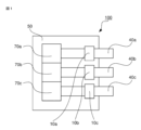
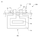
- FIG. 1 is a schematic diagram showing the general configuration of the power conversion device 100. This FIG. 1 also shows the power conversion device 100 as viewed from the underside of the substrate 50, which is a main component.
- bus bars 40a, 40b, 40c are configured to penetrate the inside of cores 10a, 10b, 10c, which have a notch at the top and a convex shape when viewed from the front, and which constitute current sensors 30a, 30b, 30c (these current sensors will be described in detail below) attached to the substrate 50 (the bus bars and convex cores will also be described in detail below), and are connected to power modules 70a, 70b, 70c provided in the power conversion device 100, respectively.
- the power modules 70a, 70b, and 70c have been described as being separate, but they may be integrated. Next, the configuration of the main parts of the power conversion device 100 will be described in detail with reference to Figures 2 to 5.
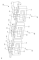
- FIG. 2 is a perspective view showing the main parts of the power conversion device 100 according to the first embodiment
- FIG. 3 is a front view showing the main parts of the power conversion device 100.
- FIG. 2 and FIG. 3 are views of the overall configuration of the power conversion device 100 with the housing surrounding the power conversion device 100 removed.
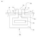
- FIG. 4 is a front view showing the current sensor 30a, which is a main part of the power conversion device 100 in FIG. 2
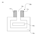
- FIG. 5 is a front view showing the convex-shaped core 10a, which is a main part of the current sensor 30a in FIG. 4.
- the power conversion device 100 includes three flat bus bars 40a, 40b, and 40c through which each phase of a three-phase current flows.
- a current sensor 30a is provided on the bus bar 40a
- a current sensor 30b is provided on the bus bar 40b
- a current sensor 30c is provided on the bus bar 40c.
- the bus bars 40a, 40b, and 40c have the same shape, and the current sensors 30a, 30b, and 30c have the same configuration, as described below.
- the power conversion device 100 also includes convex-shaped cores 10a, 10b, and 10c that constitute current sensors 30a, 30b, and 30c, and magnetoelectric conversion elements 20a, 20b, and 20c mounted on the surface of a substrate 50.
- each of the cores is a cylinder as a whole, has a notch, and a pair of columns (hereinafter also referred to as a pair of protrusions) are disposed facing each other toward the outside along the notch.
- the three bus bars 40a, 40b, and 40c are conductors through which three-phase currents, u-phase, v-phase, and w-phase, respectively, flow.
- These three bus bars are made of, for example, copper or aluminum.
- the materials are not limited to these, and other materials may be used as long as they allow current to flow.
- the cores 10a, 10b, and 10c which are formed in a convex shape when viewed from the front of the device, are each made of a magnetic material and include cores 12a, 12b, and 12c that are C-shaped when viewed from the front of the device, and a pair of protrusions 11a, 11b, and 11c (hereinafter also referred to as shield parts) that extend from the ends of the C-shaped core in the direction opposite to the positions where the bus bars 40a, 40b, and 40c are installed.
- the substrate 50 is also equipped with passive components such as an integrated circuit (IC), resistors, and capacitors, as well as other necessary electrical components, such as a circuit for controlling the operation of the power module.
- the substrate 50 has the function of detecting the current flowing through each of the bus bars 40a, 40b, and 40c using the magnetoelectric conversion elements 20a, 20b, and 20c.
- the magnetoelectric conversion elements 20a, 20b, and 20c also detect an external magnetic field, which is a magnetic field other than the magnetic field generated by the current flowing through the bus bars 40a, 40b, and 40c being measured. This external magnetic field detected by the magnetoelectric conversion elements 20a, 20b, and 20c results in an error in the current measurement.
- the magnetic field generated due to the current flowing through adjacent busbars 40b and 40c is one type of external magnetic field.
- gap 13b hereinafter also referred to as gap portion 13b
- gap 13c hereinafter also referred to as gap portion 13c
- the efficiency of magnetic collection when the convex core 10a collects the magnetic field generated by the current flowing through the busbar 40a is inversely proportional to the size of the gap in the gap 13a.
- a surface-mount type magnetoelectric conversion element can be used in the power conversion device 100 of the first embodiment.
- the magnetoelectric conversion element is surface-mounted on the substrate 50.
- the mounting form of the magnetoelectric conversion element on the substrate 50 is not limited to the surface mounting type, but by using a surface-mount type magnetoelectric conversion element, the effect of vibration on the magnetoelectric conversion element can be suppressed, and thus the accuracy of current detection of the power conversion device 100 can be improved.
- the multiple convex cores 10a, 10b, and 10c and the multiple bus bars 40a, 40b, and 40c are integrated by resin molding or the like, the multiple components can be treated as a single component. In this way, since a plurality of components can be treated as a single component, the assembly and inspection processes can be simplified, and the productivity of the power conversion device 100 can be improved.
- convex cores 10a, 10b, 10c and the bus bars 40a, 40b, 40c may be combined separately, and then integrated with resin 60 in different combinations (for example, the combination of convex core 10a and bus bar 40a).
- the current sensors 30a, 30b, and 30c are arranged side by side at the edge of the substrate 50 (close to the front), but the arrangement of the current sensors 30a, 30b, and 30c is not limited to this.
- the convex cores 10a, etc. can be arranged in the center of the substrate 50 instead of at the edge.
- the freedom of arrangement of the electrical components and current sensors 30a, 30b, and 30c mounted on the substrate 50 is improved, and the productivity of the power conversion device 100 can be improved.
- the current sensor 30a is composed of a convex-shaped core 10a and a magnetoelectric conversion element 20a
- the current sensor 30b is composed of a convex-shaped core 10b and a magnetoelectric conversion element 20b
- the current sensor 30c is composed of a convex-shaped core 10c and a magnetoelectric conversion element 20c.
- the assembly error of each of the magnetoelectric conversion elements 20a, 20b, and 20c to the gaps 13a, 13b, and 13c can be reduced.
- the pair of protrusions of the core is fixed to the through-holes of the substrate, and the convex core and the substrate are integrated, so that the error factors such as dimensional tolerances can be reduced.
- the convex cores 10a, 10b, and 10c all have the same shape, and a portion of each is attached to the substrate 50.
- the magnetoelectric conversion elements 20a, 20b, and 20c all have the same shape, and are disposed on the surface of the substrate 50 in the same manner. Therefore, in the following, the current sensor 30a will be taken as a representative example, and its configuration will be described in more detail with reference to Figs. 4 and 5 which are front views of the power conversion device.
- the current sensor 30a is composed of a convex core 10a, a magnetoelectric conversion element 20a, and a bus bar 40a.
- the convex core 10a is formed of a C-shaped core 12a and a protruding portion 11a.
- the end of the C-shaped core 12a and the protruding portion 11a are formed in pairs, facing each other symmetrically on the left and right, so that a gap 13a (gap portion 13a) is formed.
- the magnetoelectric conversion element 20a is disposed on the surface of the substrate 50 within the gap portion 13a.
- the power conversion device is shown in a plan view, so in these figures, the core 10a is referred to as a convex core 10a (the same applies below).
- the C-shaped cores 12b and 12c related to the cores 10b and 10c shown in Figs. 2 and 3 were not described in relation to Fig. 4, but these are also similar to the case of the C-shaped core 12a.
- the substrate 50 has two through holes 51a on the left and right of the magnetoelectric conversion element 20a, i.e., the magnetoelectric conversion element 20a is placed on the surface of the substrate 50 between the two through holes 51a, and converts the detected magnetic field into an electrical signal and outputs it.
- the magnetoelectric conversion element 20a is only placed on one surface of the substrate 50 facing the bus bar 40a, not on both the front and back surfaces of the substrate 50.
- the magnetoelectric conversion element 20a when the magnetoelectric conversion element 20a is placed on one side of the substrate 50, by placing the magnetoelectric conversion element 20a on the side of the substrate 50 closer to the bus bar 40a (the bottom side in FIG. 4), the magnetoelectric conversion element 20a is less susceptible to the effects of external magnetic fields. This reduces the effects of external magnetic fields that cause noise, and increases the signal-to-noise ratio (signal/noise ratio), improving the accuracy of current detection by the power conversion device 100.
- a Hall element or an MR (Magneto Resistive) element is used for the magnetoelectric conversion element 20a.
- MR elements include AMR (Anisotropic Magneto Resistive) elements, GMR (Giant Magneto Resistive) elements, and TMR (Tunnel Magneto Resistive) elements, but any element can be used.
- the magnetoelectric conversion element 20a is not limited to these elements, and other elements can be used as long as they have the function of converting the detected magnetic field into an electrical signal and outputting it.
- the location where the magnetoelectric conversion element 20a is mounted is not limited to one side of the substrate 50, and it may be mounted on the other side of the substrate 50. This is because if the magnetoelectric conversion element 20a is placed in the gap portion 13a of the convex core 10a, it is possible to detect the magnetic flux caused by the current flowing through the busbar 40a.
- the convex core 10a is integrally formed from a C-shaped core 12a made of a magnetic material and a protruding portion 11a (also called a shielding portion 11a because it has a shielding function; see the hatched portion in FIG. 5), and a bus bar 40a is installed passing through the convex core 10a.
- a pair of protrusions 11a which are the legs of the convex core 10a, are inserted into two through holes 51a located on the left and right in FIG. 4, respectively, and are arranged on the substrate 50.
- the convex core 10a which is a component of the current sensor 30a, is integrally provided with the substrate 50, and the space of both the convex core 10a and the substrate 50 is shared, so that the power conversion device 100 can be made lower in height in the direction perpendicular to the surface of the substrate 50 compared to a substrate without through holes 51a.
- the protrusions 11a which are the legs of the convex core 10a, are inserted into the through holes 51, the relative positional relationship between the gap portion 13a and the magnetoelectric conversion element 20a does not change when the magnetoelectric conversion element 20a is displaced in the vertical direction due to an external force such as vibration, and the relative positional relationship can be maintained.
- the shield portion 11a is disposed near the magnetoelectric conversion element 20a, the effect of the external magnetic field on the gap portion 13a can be reduced. This means that the current detection accuracy of the power conversion device 100 can be improved.
- the material for the convex core 10a may be, for example, electromagnetic steel sheet, iron, permalloy, or ferrite. These materials may be ferromagnetic materials such as iron, nickel, or cobalt, or materials containing ferromagnetic materials, with soft magnetic materials being particularly suitable.
- the method for manufacturing the convex core 10a may be a wound iron core or a laminated core.
- a magnetic field generated in the gap portion 13a due to the current flowing through the busbar 40a reaches the magnetoelectric conversion element 20a.
- the main direction of magnetism (magnetic line of force vector) of the magnetoelectric conversion element 20a is parallel to the arrangement surface of the substrate 50 on which the magnetoelectric conversion element 20a is arranged.
- the magnetoelectric conversion element 20a then generates a voltage according to the magnitude of the magnetic field it senses, converts the generated voltage into a current, and outputs an electrical signal corresponding to the magnitude of the measured current to a circuit provided on the substrate 50.
- the IC in the magnetoelectric conversion element 20a is equipped with a converter that converts the magnetic field into a current and converts the magnitude of the magnetic field into a current value.
- the converter it is also possible for the converter to be included in a separate IC that is different from the magnetoelectric conversion element 20a, and for this separate IC to be mounted on the substrate 50.
- Embodiment 2 A power conversion device 100a according to the second embodiment will be described below with reference to the drawings.
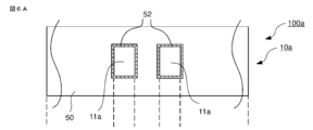
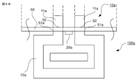
- 6A and 6B are a plan view (upper side) and a front view (lower side), respectively, showing one current sensor 30a constituting a main part of a power conversion device 100a according to the second embodiment.
- the shield portion 11a which is the two legs of the convex core 10a constituting the gap portion 13a, is inserted into two through holes 51a provided in the substrate 50, and adhesive 52 is applied to the boundary portion (the gap) between the two legs of the convex core 10a and the through hole 51a.
- the adhesive 52 is used to fix the shield portion 11a, which is the two legs of the convex core 10a, to the two through holes 51a provided in the substrate 50, thereby reducing the relative displacement between the gap portion 13a and the predetermined position of the magnetoelectric conversion element 20a caused by external forces such as vibration. This improves the accuracy of current detection in the power conversion device 100a.
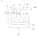
- FIG. 7 is a front view showing one current sensor 30a which is a main part of a power conversion device 100b according to the third embodiment.
- the power conversion device 100b according to the third embodiment differs from the power conversion devices shown in the first and second embodiments in that one of the two legs of the convex core 10a is inserted into one through hole 51a provided in the substrate 50 and is arranged on the substrate 50.
- the left shield part (hereinafter also referred to as the left leg) is inserted into the through hole 51 and disposed on the substrate 50.
- the left leg part of the convex core 10a and the through hole 51 can maintain the relative positional relationship between the position of the gap part 13a and the position of the magneto-electric conversion element 20a against the external force such as vibration, so that the accuracy of current detection of the power conversion device 100 can be improved compared to the case where it is affected by an external force such as vibration.
- the shield portion 11a is disposed in the vicinity of the magnetoelectric conversion element 20a, the influence of an external magnetic field on the magnetoelectric conversion element 20a due to a change in the position of the gap portion 13a can be reduced.
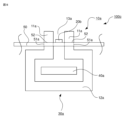
- Embodiment 4 A power conversion device 100c according to the fourth embodiment will be described below with reference to the drawings. 8 is a front view showing one current sensor 30a which is a main part of a power conversion device 100c according to embodiment 4.
- the power conversion device 100c according to embodiment 4 differs from the configurations shown in embodiments 1 and 2 in that the magnetoelectric conversion element is disposed on the upper surface of the substrate 50 on the side farther from the bus bar.
- the gap portion 13a of the convex core 10a is configured to penetrate the substrate 50 on which the magnetoelectric conversion element is arranged, so that the magnetoelectric conversion element 20b can be arranged on either the upper or lower surface of the substrate 50.
- the temperature of the bus bar 40a rises.
- the magnetic field detection accuracy of the magnetoelectric conversion element 20b changes due to the influence of temperature changes, so the influence of temperature changes from the bus bar 40a can be reduced when the magnetoelectric conversion element 20b is arranged on the surface of the substrate 50 farther from the bus bar 40a than when it is arranged on the surface closer to the bus bar 40a.
- the magnetoelectric conversion element 20a is arranged on the surface of the substrate 50 farther from the busbar 40a, as in the power conversion device 100c of the fourth embodiment, the effect of temperature changes from the busbar 40a can be reduced, improving the detection accuracy of the current flowing through the busbar 40a.
- Embodiment 5 A power conversion device 100d according to the fifth embodiment will be described below with reference to the drawings. 9 is a front view showing one current sensor 30a which is a main part of a power conversion device 100d according to embodiment 5.
- the power conversion device 100d according to embodiment 5 differs from the configurations shown in embodiments 1 and 2 in that two magnetoelectric conversion elements 20a, 20b are arranged on both sides of a substrate 50.
- the gap portion 13a of the convex core 10a is inserted into the through hole 51a of the substrate 50, so that the magnetoelectric conversion elements 20a and 20b can be arranged on both sides of the substrate 50.
- the magnetoelectric conversion elements 20a and 20b By arranging the magnetoelectric conversion elements 20a and 20b on the bottom and top surfaces of the substrate 50, respectively, it is possible to provide redundancy to the current detection function of the current sensor 30a.
- the magnetoelectric conversion element 20a arranged on one side of the substrate 50 is the main element and the magnetoelectric conversion element 20b arranged on the other side is the sub element, during normal operation the value obtained from the magnetoelectric conversion element 20a is acquired as the current detection value. If the magnetoelectric conversion element 20a is shorted to the power or ground, or if another fault occurs, it can be determined whether or not a fault has occurred in the magnetoelectric conversion element 20a by comparing the value with that of the sub magnetoelectric conversion element 20b arranged on the other side of the substrate 50. Note that the division of roles between the main and sub magnetoelectric conversion elements described above means that either the magnetoelectric conversion element 20a or 20b can be designated as the main element.
- the various features, aspects, and functions described in one or more embodiments are not limited to application to a particular embodiment, but may be applied to the embodiments alone or in various combinations. Therefore, countless modifications not exemplified are assumed within the scope of the technology disclosed in the present specification, including, for example, modifying, adding, or omitting at least one component, and further, extracting at least one component and combining it with a component of another embodiment.
- the power conversion devices according to the first to fifth embodiments can be mounted and used in various electric vehicles, for example, hybrid vehicles or electric vehicles (EVs).
- the control speed is increased in order to improve the output accuracy.
- the faster the control speed the higher the noise level tends to be. Therefore, the present power conversion device, which can improve the current detection accuracy by reducing the influence of the external magnetic field, is particularly useful.
Landscapes
- Engineering & Computer Science (AREA)
- Power Engineering (AREA)
- Measuring Instrument Details And Bridges, And Automatic Balancing Devices (AREA)
Priority Applications (2)
| Application Number | Priority Date | Filing Date | Title |
|---|---|---|---|
| JP2025525483A JPWO2024252509A1 (enExample) | 2023-06-06 | 2023-06-06 | |
| PCT/JP2023/020929 WO2024252509A1 (ja) | 2023-06-06 | 2023-06-06 | 電力変換装置および電動車両 |
Applications Claiming Priority (1)
| Application Number | Priority Date | Filing Date | Title |
|---|---|---|---|
| PCT/JP2023/020929 WO2024252509A1 (ja) | 2023-06-06 | 2023-06-06 | 電力変換装置および電動車両 |
Publications (1)
| Publication Number | Publication Date |
|---|---|
| WO2024252509A1 true WO2024252509A1 (ja) | 2024-12-12 |
Family
ID=93795319
Family Applications (1)
| Application Number | Title | Priority Date | Filing Date |
|---|---|---|---|
| PCT/JP2023/020929 Pending WO2024252509A1 (ja) | 2023-06-06 | 2023-06-06 | 電力変換装置および電動車両 |
Country Status (2)
| Country | Link |
|---|---|
| JP (1) | JPWO2024252509A1 (enExample) |
| WO (1) | WO2024252509A1 (enExample) |
Citations (6)
| Publication number | Priority date | Publication date | Assignee | Title |
|---|---|---|---|---|
| JP2011242276A (ja) * | 2010-05-19 | 2011-12-01 | Auto Network Gijutsu Kenkyusho:Kk | 電流センサ |
| JP2012247420A (ja) * | 2011-05-30 | 2012-12-13 | Melexis Technologies Nv | 電線を流れる電流を測定するための装置 |
| JP2014106101A (ja) * | 2012-11-27 | 2014-06-09 | Toyota Industries Corp | 電流センサ |
| JP2021175248A (ja) * | 2020-04-23 | 2021-11-01 | 三菱電機株式会社 | 電力変換装置 |
| JP2022519060A (ja) * | 2019-01-30 | 2022-03-18 | レム・インターナショナル・エスエイ | 磁界検出器モジュールを備えた電流変換器 |
| WO2023090228A1 (ja) * | 2021-11-16 | 2023-05-25 | 株式会社デンソー | 電流センサ |
-
2023
- 2023-06-06 WO PCT/JP2023/020929 patent/WO2024252509A1/ja active Pending
- 2023-06-06 JP JP2025525483A patent/JPWO2024252509A1/ja active Pending
Patent Citations (6)
| Publication number | Priority date | Publication date | Assignee | Title |
|---|---|---|---|---|
| JP2011242276A (ja) * | 2010-05-19 | 2011-12-01 | Auto Network Gijutsu Kenkyusho:Kk | 電流センサ |
| JP2012247420A (ja) * | 2011-05-30 | 2012-12-13 | Melexis Technologies Nv | 電線を流れる電流を測定するための装置 |
| JP2014106101A (ja) * | 2012-11-27 | 2014-06-09 | Toyota Industries Corp | 電流センサ |
| JP2022519060A (ja) * | 2019-01-30 | 2022-03-18 | レム・インターナショナル・エスエイ | 磁界検出器モジュールを備えた電流変換器 |
| JP2021175248A (ja) * | 2020-04-23 | 2021-11-01 | 三菱電機株式会社 | 電力変換装置 |
| WO2023090228A1 (ja) * | 2021-11-16 | 2023-05-25 | 株式会社デンソー | 電流センサ |
Also Published As
| Publication number | Publication date |
|---|---|
| JPWO2024252509A1 (enExample) | 2024-12-12 |
Similar Documents
| Publication | Publication Date | Title |
|---|---|---|
| JP6350785B2 (ja) | インバータ装置 | |
| US20130169267A1 (en) | Current sensor | |
| US11105831B2 (en) | Current sensor | |
| US10746821B2 (en) | Current sensor | |
| JP6711086B2 (ja) | 電流センサ | |
| JP6504260B2 (ja) | 電流センサおよびこれを備える電力変換装置 | |
| US11041887B2 (en) | Current sensor | |
| JP2007121283A (ja) | 電流測定値用組立体群 | |
| CN114144684B (zh) | 用于交变电流的频率补偿测量的基于磁场的电流传感器 | |
| JP2019109126A (ja) | 電流センサ | |
| JP6825023B2 (ja) | 電力変換装置 | |
| JP2018096795A (ja) | 電流センサ | |
| CN113495183A (zh) | 电流传感器及其制造方法、电控制装置、以及电流传感器的设计方法 | |
| JP4766477B2 (ja) | 電流検出装置およびそれを備えた電力変換装置 | |
| WO2014203862A2 (ja) | 電流センサ | |
| US11199563B2 (en) | Electric current sensor | |
| CN113644830B (zh) | 功率转换装置 | |
| WO2024252509A1 (ja) | 電力変換装置および電動車両 | |
| US20220334147A1 (en) | Current sensor | |
| Kim et al. | Coreless hall current sensor for automotive inverters decoupling cross-coupled field | |
| JP2012063285A (ja) | 電流センサ | |
| JP2019007935A (ja) | 電流センサ | |
| JP2020183927A (ja) | 電流センサ | |
| JP2020012671A (ja) | 電流センサ | |
| WO2024116410A1 (ja) | 電流検出装置および電力変換装置 |
Legal Events
| Date | Code | Title | Description |
|---|---|---|---|
| 121 | Ep: the epo has been informed by wipo that ep was designated in this application |
Ref document number: 23940615 Country of ref document: EP Kind code of ref document: A1 |
|
| WWE | Wipo information: entry into national phase |
Ref document number: 2025525483 Country of ref document: JP |