WO2024252482A1 - 線路セグメントを組み立てる方法、治具、線路セグメント、及び線路 - Google Patents
線路セグメントを組み立てる方法、治具、線路セグメント、及び線路 Download PDFInfo
- Publication number
- WO2024252482A1 WO2024252482A1 PCT/JP2023/020848 JP2023020848W WO2024252482A1 WO 2024252482 A1 WO2024252482 A1 WO 2024252482A1 JP 2023020848 W JP2023020848 W JP 2023020848W WO 2024252482 A1 WO2024252482 A1 WO 2024252482A1
- Authority
- WO
- WIPO (PCT)
- Prior art keywords
- rack gear
- base
- jig
- rail
- face
- Prior art date
- Legal status (The legal status is an assumption and is not a legal conclusion. Google has not performed a legal analysis and makes no representation as to the accuracy of the status listed.)
- Ceased
Links
Images







Classifications
-
- E—FIXED CONSTRUCTIONS
- E01—CONSTRUCTION OF ROADS, RAILWAYS, OR BRIDGES
- E01B—PERMANENT WAY; PERMANENT-WAY TOOLS; MACHINES FOR MAKING RAILWAYS OF ALL KINDS
- E01B29/00—Laying, rebuilding, or taking-up tracks; Tools or machines therefor
- E01B29/02—Transporting, laying, removing, or renewing lengths of assembled track, assembled switches, or assembled crossings
Definitions
- the present disclosure relates to a method for assembling track segments, a jig, a track segment, and a track.
- Patent Document 1 Trains for running gears equipped with rack gears and rails are known (for example, Patent Document 1).
- a railway line is constructed by laying multiple track segments, each of which has a rack gear and a rail, side by side.
- a certain gap may be provided between the rack gears of two adjacent track segments.
- a jig in another aspect of the present disclosure, includes a base, a rail, and a rack gear, and is installed on the base to assemble track segments that constitute a track on which a bogie runs.
- the jig includes a positioning rack gear that is disposed at an end of the base in the running direction so as to extend in the running direction of the bogie.
- the positioning rack gear engages with a rack gear fixed to the base, thereby positioning the rack gear at a predetermined position relative to the base.
- a track segment constituting the track on which the bogie runs includes a base, a rail laid on the base so as to extend in the running direction of the bogie and on which the bogie runs, and a rack gear laid on the base so as to extend in the running direction and engaging with a drive unit provided on the bogie to generate power for running the bogie on the rail.
- One end face of the rail in the running direction is positioned offset in one direction of the running direction from one end face of the rack gear in the running direction
- the other end face of the rail in the running direction is positioned offset in the other direction of the running direction from the other end face of the rack gear in the running direction.
- FIG. 2 is a perspective view of a traveling device according to one embodiment.
- FIG. 2 is a top view of the line shown in FIG. 1 .
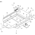
- FIG. 3 is a perspective view of the line segment shown in FIG. 2 .
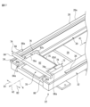
- FIG. 4 is an enlarged perspective view of one end of the base of the line segment shown in FIG. 3 .
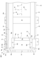
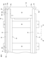
- 4 is an enlarged top view of the other end of the base of the line segment shown in FIG. 3.
- FIG. FIG. 4 is an enlarged perspective view of one end of the line segment shown in FIG. 3 .
- FIG. 7 is an enlarged top view of the end of the line segment shown in FIG. 6 .
- FIG. 4 is an enlarged perspective view of the other end of the line segment shown in FIG. 3 .
- FIG. 9 is an enlarged top view of the end of the line segment shown in FIG. 8 .
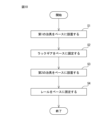
- 4 is a flowchart illustrating an example of a method for assembling track segments.
- FIG. 2 is a perspective view of a first jig for assembling the track segments.
- FIG. 12 is a perspective view showing a state in which the first jig shown in FIG. 11 is installed on a base.
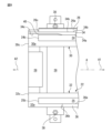
- FIG. 13 is a top view of the first jig and the base shown in FIG. 12 .
- FIG. 14 is a top view showing a state in which a rack gear is fixed to the base shown in FIG. 13 .
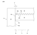
- FIG. 15 is an enlarged view of the vicinity of an end face of the rack gear shown in FIG. 14 .
- FIG. 13 is an exploded perspective view of a second jig for assembling the track segments.
- FIG. 17 is a perspective view showing a state in which the second jig shown in FIG. 16 is installed on a base.
- FIG. 18 is a top view of the second jig and the base shown in FIG. 17 viewed from above.
- FIG. 19 is an enlarged view of the vicinity of an end face of the rack gear shown in FIG. 18 .
- 15 is a top view showing a state in which a rail is fixed to the base shown in FIG. 14.
- FIG. 21 is an enlarged view of the vicinity of an end face of the rack gear shown in FIG. 20 .
- 18 is a perspective view showing a state in which a rail is fixed to the base shown in FIG. 17.
- FIG. 19 is a top view showing a state in which a rail is fixed to the base shown in FIG. 18.
- FIG. 24 is an enlarged view of the vicinity of an end face of the rack gear shown in FIG. 23 .
- FIG. 3 is an enlarged view of a connection portion of two line segments shown in FIG. 2 . This is a close-up of the rack gear connection between two adjacent track segments.
- the traveling device 10 is for transporting industrial machinery, such as a robot that performs a specified task on a workpiece, in a traveling direction A.
- the traveling direction A1 the direction indicated by the arrow A1 in the figure will be referred to as one traveling direction (hereinafter referred to as "direction A1")
- the direction indicated by the arrow A2 in the figure will be referred to as the other traveling direction (hereinafter referred to as "direction A2").
- the traveling device 10 comprises a track 12, a bogie 14, and a drive unit 16.
- the bogie 14 travels on the track 12 in a traveling direction A.
- industrial machinery is placed on the bogie 14.
- the drive unit 16 has, for example, a servo motor, and is provided on the bogie 14.
- the drive unit 16 generates power to travel the bogie 14. More specifically, the drive unit 16 has a pinion gear 16a, and drives the pinion gear 16a to rotate in the forward and reverse directions.
- the track 12 is laid on the ground. As shown in FIG. 2, the track 12 has a number of track segments 20 arranged so as to be aligned in the running direction A. Note that FIG. 2 shows an example in which the track 12 is made up of two track segments 20, but any number of track segments 20 may be arranged in the running direction A.
- each track segment 20 comprises a base 22, a pair of rails 24 and 25, and a rack gear 26.
- the base 22 is fixedly installed on the ground. Specifically, as shown in Figures 3 to 5, the base 22 has a number of sleeper sections 28, a pair of support beams 30 and 32, and a pair of pressing sections 34 and 36.
- the multiple sleeper sections 28 are arranged at approximately equal intervals in the running direction A.
- Each sleeper section 28 is a roughly rectangular flat plate member, and is fixed to the ground by fasteners 38 such as bolts.
- the support beams 30 and 32 extend straight in the running direction A and are parallel to each other.
- the support beams 30 and 32 are laid on top of the sleeper sections 28 by fasteners such as bolts (not shown) or by welding, etc.
- the pressing portion 34 is integrally provided with the support beam 30 so as to protrude upward from the upper surface 30a of the support beam 30, and extends straight in the running direction A. More specifically, the pressing portion 34 extends from the end surface 30b of the support beam 30 in the direction A1 toward the direction A2, and terminates at the end surface 30c of the support beam 30 in the direction A2, as shown in FIG. 5.
- the pressing portion 34 has pressing surfaces 34a and 34b and a recessed surface 34c.
- the pressing surfaces 34a and 34b are planes that extend straight in the running direction A and are perpendicular to the upper surface 30a of the support beam 30.
- the pressing surface 34a extends from the end surface 30b of the support beam 30 to the end edge 34d.
- the end edge 34d is disposed at a position spaced apart from the end surface 30c of the support beam 30 in the direction A1.
- the recessed surface 34c is connected to the end edge 34d of the pressing surface 34a.
- the recessed surface 34c is provided on the pressing portion 34 so as to be recessed from the pressing surface 34a in the direction B1 perpendicular to the running direction A.
- the pressing portion 36 is integral with the support beam 32 so as to protrude upward from the upper surface 32a of the support beam 32, and extends straight in the traveling direction A. More specifically, the pressing portion 36 extends from the end surface 32b of the support beam 32 in the direction A1 toward the direction A2, and terminates at the end surface 36b as shown in FIG. 5. This end surface 36b is disposed at a position farther away in the direction A1 than the end surface 32c of the support beam 32.
- the pressing portion 36 has a pressing surface 36a.
- the pressing surface 36a is perpendicular to the upper surface 32a of the support beam 32 and extends straight in the traveling direction A.
- the pair of rails 24 and 25 and the rack gear 26 are laid on the base 22.
- the rail 24 is fixed to the upper surface 30a of the support beam 30 by a fastener such as a bolt (not shown) while being pressed against the pressing surface 34a of the pressing portion 34.
- a fastener such as a bolt (not shown)
- the rail 25 is fixed to the upper surface 32a of the support beam 32 by a fastener such as a bolt (not shown) while being pressed against the pressing surface 36a of the pressing portion 36. This positions the rail 25 so that it extends straight in the running direction A.
- the rack gear 26 is fixed to the upper surface 30a of the support beam 30 by a fastener such as a bolt (not shown) while being pressed against the pressing surface 34b of the pressing portion 34. This positions the rack gear 26 so that it extends straight in the running direction A.
- the rack gear 26 has a plurality of teeth 26a on the side opposite the pressing portion 34. These teeth 26a are aligned in the running direction A to have a predetermined pitch p1.
- the pinion gear 16a (FIG. 1) of the drive unit 16 described above meshes with the teeth 26a, and the drive unit 16 rotates the pinion gear 16a to generate power that causes the cart 14 to run on the rails 24 and 25 in the running direction A.
- the end face 24a in the direction A1 of the rail 24, the end face 25a in the direction A1 of the rail 25, and the end face 26b in the direction A1 of the rack gear 26 are arranged to protrude in the direction A1 further than the end faces 30b and 32b of the support beams 30 and 32 of the base 22.
- the end face 24b in the direction A2 of the rail 24, the end face 25b in the direction A2 of the rail 25, and the end face 26c in the direction A2 of the rack gear 26 are arranged to recede in the direction A1 further than the end faces 30c and 32c of the support beams 30 and 32 of the base 22.
- the recessed surface 34c of the pressing portion 34 forms a gap 40 between the pressing portion 34 and the end of the rail 24 in the direction A2. Therefore, the pressing portion 34 does not come into contact with the end of the rail 24 in the direction A2.
- the end face 36b of the pressing portion 36 in the direction A2 is positioned further away in the direction A1 than the end face 25b of the rail 25. Therefore, the pressing portion 36 does not come into contact with the end of the rail 25 in the direction A2.
- step S1 the manufacturer installs the jig 50 (first jig) at the end of the base 22, which has been prepared in advance, in the direction A1.
- the jig 50 will be described with reference to FIG. 11.
- the jig 50 comprises a main body 52, arms 54 and 56, and a positioning rack gear 58.
- the main body 52 is a flat plate member having a roughly rectangular outer shape, and has a fixing portion 53 for fixing the main body 52 to the base 22.
- the fixing portion 53 is a through hole capable of receiving a fixing device (not shown) such as a positioning pin or a bolt, and a plurality of fixing portions 53 are provided in the main body 52.
- the fixing portion 53 is a long hole.
- fixing portions 31 are formed on the support beams 30 and 32 of the base 22, respectively, so as to correspond to the fixing portions 53.
- the fixing portion 31 is a hole capable of receiving a fixing device.
- the arm 54 is formed integrally with the main body 52 so as to extend in one direction from the main body 52.
- the arm 54 has an abutment surface 54a (first abutment surface).
- the abutment surface 54a extends in one direction from one side surface 52c of the main body 52, and extends between the main body 52 and the positioning rack gear 58.
- the arm 56 is formed integrally with the main body 52 so as to extend in the other direction from the main body 52.
- the arm 56 has an abutment surface 56a (first abutment surface).
- the abutment surface 56a extends in the other direction from the other side surface 52d of the main body 52.
- the positioning rack gear 58 (first positioning rack gear) is fixed to the abutment surface 54a so as to extend from the abutment surface 54a.
- the positioning rack gear 58 extends to face the side surface 52c of the main body 52, and has a plurality of teeth 58a on the side facing the side surface 52c. These teeth 58a are aligned to have a predetermined pitch p2.
- the manufacturer inserts multiple fasteners (positioning pins, bolts, etc.) into the fasteners 53 formed on the main body 52 and the fasteners 31 formed on the support beams 30 and 32 of the base 22, respectively, and fixes the main body 52 to the support beams 30 and 32 with the fasteners.
- the jig 50 is installed at the end of the base 22 in the direction A1, as shown in Figures 12 and 13.
- the jig 50 When the jig 50 is installed on the base 22, the lower surface 52b of the main body 52 abuts against the upper surfaces 30a and 32a of the support beams 30 and 32.
- the positioning rack gear 58 of the jig 50 is disposed at the end of the base 22 in the direction A1 so as to be spaced apart from the main body 52 in a direction B1 perpendicular to the running direction A and to extend parallel to the running direction A.
- the abutment surface 54a is arranged to extend from the side surface 52c of the main body portion 52 in the direction B1, while the abutment surface 56a is arranged to extend from the side surface 52d of the main body portion 52 in the direction B2 opposite to the direction B1.
- the abutment surfaces 54a and 56a are arranged to be perpendicular to the running direction A (or face the direction A2).
- the fixing portion 53 as a long hole is arranged so that its longitudinal direction is parallel to the directions B1 and B2. This fixing portion 53 allows the jig 50 to be displaced in the directions B1 and B2.
- step S2 the manufacturer fixes the rack gear 26, which has been prepared in advance, to the base 22. Specifically, the manufacturer meshes the teeth 26a of the rack gear 26, which has been prepared in advance, with the teeth 58a provided on the positioning rack gear 58 of the jig 50 installed on the base 22 in step S1. The manufacturer then abuts the rack gear 26 against the upper surface 30a of the support beam 30, and presses it against the pressing surface 34b of the pressing portion 34.
- the fixture 50 can be displaced in directions B1 and B2 relative to the base 22 by the fixing portion 53 in the form of a long hole. Therefore, the manufacturer can fine-tune the position of the fixture 50 in directions B1 or B2 to mesh the rack gear 26 with the positioning rack gear 58 and press it against the pressing surface 34b. As a result, the rack gear 26 is positioned to extend parallel to the running direction A. The manufacturer then fixes the rack gear 26 to the base 22 with a fastener (not shown) such as a bolt.
- a fastener not shown
- Figure 14 shows the rack gear 26 fixed to the base 22.
- the rack gear 26 By fixing the rack gear 26 to the base 22 while the rack gear 26 is engaged with the positioning rack gear 58, the rack gear 26 can be positioned at a predetermined position Pr relative to the base 22.
- a gap 60 is formed between the end face 26b of the rack gear 26 in the direction A1 and the abutment surface 54a of the jig 50.
- the abutment surface 54a and the positioning rack gear 58 are machined with high precision so that this distance ⁇ has a tolerance of, for example, -0.05 to -0.1.
- step S3 the manufacturer installs the jig 70 (second jig) at the end of the base 22 in the direction A2.
- the jig 70 will be described below with reference to FIG. 16.
- the jig 70 has a first jig member 72 and a second jig member 74.
- the first jig member 72 is fixed to the base 22.
- the first jig member 72 has a pedestal portion 75 and a pair of engagement walls 76 and 78.
- the base portion 75 is a flat plate member having an upper surface 75a.
- the engagement wall 76 is formed integrally with the base portion 75 so as to protrude upward from one end of the base portion 75, and has an engagement surface 76a.
- the engagement wall 78 is formed integrally with the base portion 75 so as to protrude upward from the other end of the base portion 75, and has an engagement surface 78a.
- the engagement surfaces 76a and 78a face each other and are perpendicular to the upper surface 75a of the base portion 75.
- a rectangular prism-shaped groove G is defined by the upper surface 75a of the base portion 75 and the engagement surfaces 76a and 78a of the engagement walls 76 and 78.
- the first jig member 72 has a plurality of fixing portions 80 for fixing the first jig member 72 to the base 22.
- the fixing portions 80 are provided on the engagement walls 76 and 78, respectively.
- the fixing portions 80 are through holes capable of receiving fixing devices such as positioning pins or bolts, and are elongated holes having a longitudinal direction, similar to the fixing portion 53 described above.
- the support beams 30 and 32 of the base 22 are each formed with fixing portions 33 corresponding to the fixing portions 80.
- the fixing portions 33 are holes capable of receiving fixing devices. It should be understood that the fixing portions 33 provided on the support beam 32 are not shown in FIG. 16.
- the second jig member 74 has a shape that is approximately symmetrical to the jig 50 described above. Specifically, the second jig member 74 has a main body 82, arms 84 and 86, and a positioning rack gear 88.
- the main body 82 is a flat plate member having an approximately rectangular outer shape.
- the arm 84 is formed integrally with the main body 82 so as to extend in one direction from the main body 82, and has an abutment surface 84a (second abutment surface).
- the abutment surface 84a extends in one direction from one side surface 82c of the main body 82, and extends between the main body 82 and the positioning rack gear 88.
- the arm 86 is formed integrally with the main body 82 so as to extend in the other direction from the main body 82, and has an abutment surface 86a (second abutment surface).
- the abutment surface 86a extends in the other direction from the other side surface 82d of the main body 82.
- the positioning rack gear 88 (second positioning rack gear) is fixed to the abutment surface 84a so as to extend from the abutment surface 84a.
- the positioning rack gear 88 extends to face the side surface 82c of the main body 82, and has a plurality of teeth 88a on the side facing the side surface 82c. These teeth 88a are aligned to have a predetermined pitch p3.
- the main body 82 is slidably received in a groove G defined in the first jig member 72, and the side surfaces 82c and 82d of the main body 82 slidably engage with the engagement surfaces 76a and 78a, respectively. Therefore, when the main body 82 is received in the groove G, the second jig member 74 is displaceable relative to the first jig member 72.
- the manufacturer first inserts multiple fasteners (positioning pins, bolts, etc.) into the fasteners 80 formed on the first jig member 72 and the fasteners 33 formed on the support beams 30 and 32 of the base 22, respectively, and fixes the first jig member 72 to the support beams 30 and 32 with the fasteners.
- the fasteners 80 as long holes are positioned so that their longitudinal direction is parallel to the directions B1 and B2 that are perpendicular to the running direction A.
- the fasteners 80 allow the first jig member 72 to be displaced in the directions B1 and B2.
- the manufacturer meshes the teeth 88a of the positioning rack gear 88 of the second jig member 74 with the teeth 26a of the rack gear 26 fixed to the base 22 in step S2, and fits the body 82 of the second jig member 74 into the groove G of the first jig member 72.
- the second jig member 74 fits into the first jig member 72 with the positioning rack gear 88 engaged with the rack gear 26.
- the fixing portion 80 serving as a long hole allows the first jig member 72 to be displaced relative to the base 22 in directions B1 and B2 perpendicular to the traveling direction A. Therefore, the manufacturer can finely adjust the position of the first jig member 72 in the direction B1 or B2 to mesh the positioning rack gear 58 with the rack gear 26 and fit the main body portion 82 of the second jig member 74 into the groove G of the first jig member 72.
- the lower surface 72a (FIG. 16) of the first jig member 72 abuts against the upper surfaces 30a and 32a of the support beams 30 and 32, and the lower surface 82b (FIG. 16) of the main body portion 82 of the second jig member 74 abuts against the upper surface 75a of the base portion 75 of the first jig member 72.
- the engagement walls 76 and 78 (i.e., engagement surfaces 76a and 78a) of the first jig member 72 are arranged to extend parallel to the running direction A.
- the positioning rack gear 88 is arranged at the end of the base 22 in the direction A2, spaced from the main body portion 82 in the direction B1 perpendicular to the running direction A and extending parallel to the running direction A.
- the abutment surface 84a is arranged to extend in the direction B1 from the side surface 82c of the main body portion 82, while the abutment surface 86a is arranged to extend in the direction B2 from the side surface 82d of the main body portion 82.
- the abutment surfaces 84a and 86a are arranged to be perpendicular to the running direction A (or facing the direction A1).
- the main body 82 of the second jig member 74 engages with the engagement walls 76 and 78 of the first jig member 72, thereby restricting the movement of the second jig member 74 in the directions B1 and B2 relative to the first jig member 72.
- the engagement between the positioning rack gear 88 and the rack gear 26 also restricts the movement of the second jig member 74 in the running direction A.
- the second jig member 74 is fixed to the base 22.
- a pitch error ⁇ may occur in the pitch p1 of the rack gear 26. This error ⁇ may occur for all teeth 26a of the rack gear 26, so a cumulative pitch error ⁇ may occur in the rack gear 26. Due to this cumulative pitch error ⁇ , a dimensional error ⁇ may occur in the overall length Lg of the rack gear 26.
- the second jig member 74 is displaceable in the running direction A relative to the first jig member 72 fixed to the base 22 by the engagement between the main body portion 82 and the engagement walls 76 and 78.
- the positioning rack gear 88 can be engaged with the rack gear 26 to fit the main body 82 into the groove G of the first jig member 72.
- the second jig member 74 can be fixed at a predetermined position relative to the base 22, based on the overall length Lg of the rack gear 26.
- step S3 the jig 70 (first jig member 72 and second jig member 74) is installed at the end of the base 22 in the direction A2.
- the jig 70 is installed on the base 22 as shown in Figures 17 and 18, a gap 90 is formed between the end surface 26c of the rack gear 26 in the direction A2 and the abutment surface 84a of the second jig member 74 as shown in Figure 19.
- the abutment surface 84a and the positioning rack gear 88 are machined with high precision so that this distance ⁇ ' has a tolerance of, for example, -0.05 to -0.1.
- step S4 the manufacturer fixes the rails 24 and 25 to the base 22. Specifically, the manufacturer places the rails 24 and 25 between the jigs 50 and 70 installed at both ends of the base 22 so that they extend in the running direction A. At this time, the manufacturer abuts the end surface 24a of the rail 24 in the direction A1 against the abutment surface 54a of the jig 50, as shown in Figures 20 and 21.
- the manufacturer also butts the end face 24b of the rail 24 in the direction A2 against the butt surface 84a of the jig 70 (specifically, the second jig member 74) as shown in Figures 22 to 24.
- the manufacturer then abuts the rail 24 against the upper surface 30a of the support beam 30 and presses it against the pressing surface 34a of the pressing portion 34.
- the rail 24 is positioned to extend parallel to the running direction A.
- the manufacturer abuts end face 25a of rail 25 in direction A1 against abutment surface 56a of jig 50, and as shown in FIGS. 22 and 23, end face 25b of rail 25 in direction A2 against abutment surface 86a of jig 70 (second jig member 74). Then, the manufacturer abuts rail 25 against upper surface 32a of support beam 32 and presses it against pressing surface 36a of pressing portion 36. As a result, rail 25 is positioned to extend parallel to running direction A. Then, the manufacturer fixes rails 24 and 25 to base 22 with fasteners such as bolts (not shown).
- the manufacturer may determine the tolerance ⁇ of the overall length Lr of the rails 24 and 25, taking into account the dimensional error ⁇ of the rack gear 26. Specifically, the manufacturer determines the tolerance ⁇ of the rails 24 and 25 to be equal to or less than the dimensional error ⁇ of the rack gear 26, and fabricates the rails 24 and 25 in advance so that the error in the overall length Lr of the rails 24 and 25 falls within the tolerance ⁇ .
- the manufacturer may machine end faces 24a or 24b of rail 24, or end faces 25a or 25b of rail 25, to fit the error in overall length Lr within tolerance ⁇ .
- rails 24 and 25 can be positioned between jigs 50 and 70 so that they abut against abutment surfaces 54a, 56a, 84a, and 86a.
- the track segment 20 shown in FIG. 3 is assembled.
- the end faces 24a and 25a of the rails 24 and 25 in the direction A1 are positioned slightly offset in the direction A1 from the end face 26b of the rack gear 26 in the direction A1 (see FIG. 21).
- the end faces 24b and 25b of the rails 24 and 25 in the direction A2 are positioned slightly offset in the direction A2 from the end face 26c of the rack gear 26 in the direction A2 (see FIG. 24).
- the rails 24 and 25 are positioned by the jigs 50 and 70 in a predetermined positional relationship with respect to the rack gear 26 (more specifically, a positional relationship in which the end faces 24a, 24b, 24b, and 25b of the rails 24 and 25 are positioned offset from the end faces 26b and 26c of the rack gear 26) based on the overall length Lg (or end faces 26b and 26c) of the rack gear 26.
- the manufacturer removes the jigs 50 and 70 from the base 22.
- the manufacturer can mass-produce the track segments 20 using the assembly method of FIG. 10.
- the manufacturer then arranges any number of track segments 20 as required so that they are aligned in the running direction A, and fixes the sleeper section 28 of each track segment 20 to the ground with fasteners 38.
- FIG. 2 and FIG. 25 multiple track segments 20 are laid in the running direction A, and a track 12 made up of the multiple track segments 20 is assembled.
- the end faces 30c of the support beam 30, 32c of the support beam 32, 24b of the rail 24, 25b of the rail 25, and 26c of the rack gear 26 of the track segment 20 arranged on the direction A1 side face each other in the running direction A with the end faces 30b of the support beam 30, 32b of the support beam 32, 24a of the rail 24, 25a of the rail 25, and 26b of the rack gear 26 of the track segment 20 arranged on the direction A2 side.
- the ends of the rails 24 and 25 and the rack gear 26 in the direction A1 of the track segment 20 on the direction A2 side are arranged on the upper faces 30a and 32a of the base 22 (specifically, the support beams 30 and 32) of the track segment 20 on the direction A1 side.
- the ends of the rails 24 and 25 in the direction A1 may be provided with fixing portions (e.g., through holes that can accept fasteners such as bolts) for fixing to the base 22.
- the manufacturer may then fix the fixing portions formed on the rails 24 and 25 of the track segment 20 on the direction A2 side to the base 22 (support beams 30 and 32) of the track segment 20 on the direction A1 side with fasteners such as bolts.
- a pitch error ⁇ can occur in the rack gear 26.
- the pitch error ⁇ into consideration, in order to ensure pitch p1 between the teeth 26a' and 26a", it is necessary to provide a gap 92 in the running direction A, as shown in FIG. 26. This ensures a common pitch p1 in the two rack gears 26 aligned in the running direction A.
- the pinion gear 16a of the drive unit 16 rolls on the teeth 26a of the rack gear 26 while meshing with the teeth 26a, it is possible to prevent stress from being applied to the rack gear 26 or the pinion gear 16a.
- end faces 24a and 25a of rails 24 and 25 in direction A1 are positioned offset in direction A1 from end face 26b of rack gear 26 in direction A1 (FIG. 21). Also, end faces 24b and 25b of rails 24 and 25 in direction A2 are positioned offset in direction A2 from end face 26c of rack gear 26 in direction A2 (FIG. 24).
- the manufacturer installs the first jig 50 having the first positioning rack gear 58 at the end of the base 22 in the direction A1 (step S1), engages the rack gear 26 with the first positioning rack gear 58, and fixes it to the base 22 so that it extends in the running direction A (step S2).
- the manufacturer also installs the second jig 70 having the second positioning rack gear 88 at the end of the base 22 in the direction A2 so that the second positioning rack gear 88 engages with the rack gear 26 (step S3).
- the manufacturer places the rails 24, 25 between the first jig 50 and the second jig 70 so that they extend in the running direction A, and fixes them to the base 22 (step S3).
- the rails 24 and 25 can be positioned in a predetermined positional relationship with respect to the rack gear 26, based on the overall length Lg of the rack gear 26.
- the rails 24 and 25 and the rack gear 26 can be laid with high precision while maintaining the above-mentioned gap 92 ( Figure 26).
- a track 12 having a desired overall length in the running direction A can be easily produced.
- the jigs 50 and 70 are arranged so as to intersect with the running direction A, and have abutment surfaces 54a, 56a, 84a, and 86a against which the end faces 24a, 24b, 25a, and 25b in the running direction A of the rails 24 and 25 fixed to the base 22 abut.
- the first jig 50 has first abutment surfaces 54a and 56a that are arranged so as to intersect with the running direction A when the first jig is installed on the base 22.
- the second jig 70 also has second abutment surfaces 84a, 86a that are positioned to intersect with the running direction A when installed on the base 22.
- the manufacturer fixes the rails 24, 25 to the base 22, the manufacturer abuts the end faces 24a, 25a of the rails 24, 25 in the direction A1 against the first abutment surfaces 54a, 56a, and abuts the end faces 24b, 25b of the rails 24, 25 in the direction A2 against the second abutment surfaces 84a, 86a.
- the abutment surface 54a or 56a, or the abutment surface 84a or 86a may be omitted from the jig 50 or 70.
- the jig 50 (or 70) may have only the positioning rack gear 58 (or 88).
- the manufacturer may directly fix the positioning rack gear 58 (or 88) to the base 22 with a fixture.
- step S4 the manufacturer may fix rails 24 and 25 to base 22 in the above-mentioned positional relationship, using the end face of positioning rack gear 58 in direction A1 and the end face of positioning rack gear 88 in direction A2 as references.
- the manufacturer may provide markers on base 22 that indicate the positions of the end faces of positioning rack gear 58 and positioning rack gear 88 in running direction A, and fix rails 24 and 25 using the markers as references.
- a gap 60 is formed between the end face 26b of the rack gear 26 in the direction A1 and the first abutment surface 54a (FIG. 15).
- a gap 90 is formed between the end face 26c of the rack gear 26 in the direction A2 and the second abutment surface 84a (FIG. 19).
- the end faces 24a, 24b, 25a, and 25b of the rails 24 and 25 can be arranged offset relative to the end faces 26b and 26c of the rack gear 26 ( Figures 21 and 24).
- the end faces 24a and 25a of the rails 24 and 25 of one track segment 20 and the end faces 24b and 25b of the rails 24 and 25 of the other track segment 20 can be abutted against each other while reliably providing the above-mentioned gap 92 (or the gap formed between them can be minimized).
- the end faces 26b and 26c of the rack gear 26 may be abutted against the abutment faces 54a and 84a, respectively, without forming the gaps 60 and 90.
- the jigs 50, 70 are installed on the base 22 to assemble the track segments 20 that make up the track 12, and include positioning rack gears 58, 88 that are arranged at the ends of the base 22 in the running direction A so as to extend in the running direction A.
- the positioning rack gears 58, 88 engage with the rack gear 26 fixed to the base 22, thereby positioning the rack gear 26 at a predetermined position Pr relative to the base 22.
- the rack gear 26 can be advantageously positioned relative to the base 22 at a position Pr where the above-mentioned gap 92 can be set (i.e., where a common pitch p1 can be ensured).
- the positioning rack gears 58, 88 are provided on the abutment surfaces 54a, 84a so as to extend from the abutment surfaces 54a, 84a.
- the jigs 50, 70 further include main body portions 52, 82 that are spaced apart from the positioning rack gears 58, 88 in a direction B2 perpendicular to the running direction A.
- the abutment surfaces 54a, 84a extend between the positioning rack gears 58, 88 and the main body portions 52, 82.
- the jig 50, 70 has a first abutment surface 54a, 56a extending from the main body portion 52, 82 in a direction B1 perpendicular to the running direction A, and a second abutment surface 56a, 86a extending from the main body portion 52, 82 in a direction B2 opposite to the direction B1.
- the end surfaces 24a, 24b of the first rail 24 arranged between the positioning rack gear 58, 88 and the main body portion 52, 82 abut against the first abutment surface 54a, 56a.
- the end faces 25a, 25b of the second rail 25 arranged on the side of the main body 52, 82 opposite the first rail 24 are abutted against the second abutment surfaces 56a, 86a.
- the rail 24 may be omitted from the track segment 20.
- the abutment surfaces 54a and 84a against which the rail 24 abuts are omitted.
- the rail 25 may be omitted from the track segment 20.
- the arm 86 may be omitted from the jigs 50 and 70.
- the main body 52 of the jig 50 has a fixing portion 53 for fixing to the base 22.
- the fixing portion 53 is not limited to the main body 52, and may be provided, for example, on the positioning rack gear 58, the arm 54, or the arm 56.
- the jig 70 includes a first jig member 72 having a fixing portion 80 for fixing to the base 22, and a second jig member 74 having a positioning rack gear 88 that engages with the first jig member 72 so as to be displaceable in the running direction A.
- the positioning rack gear 88 can be reliably engaged with the rack gear 26.
- the jig 70 may be composed of a single member of an integral shape similar to the jig 50.
- the fixing portions 53 and 80 are described as through holes that can receive a fixing device.
- the fixing portion 53 or 80 may be configured as a protrusion that can engage with the base 22.
- the fixing portion 53 or 80 may also have a first fixing portion that is a through hole and a second fixing portion that is a protrusion.
- the track segment 20 constitutes the track 12 on which the bogie 14 runs, and includes a base 22, rails 24, 25 laid on the base 22 so as to extend in the running direction A and on which the bogie 14 runs, and a rack gear 26 laid on the base 22 so as to extend in the running direction A and engaging with a drive unit 16 provided on the bogie 14 to generate power for running the bogie 14 on the rails 24, 25.
- the end faces 24a, 25a of the rails 24, 25 in the direction A1 are positioned offset in the direction A1 from the end face 26b of the rack gear 26 in the direction A1 (FIG. 21).
- the end faces 24b, 25b of the rails 24, 25 in the direction A2 are positioned offset in the direction A2 from the end face 26c of the rack gear 26 in the direction A2 (FIG. 24).
- the end faces 24a, 25a in the direction A1 of the rails 24, 25 and the end face 26b in the direction A1 of the rack gear 26 are positioned to protrude in the direction A1 further than the end faces 30b, 32b in the direction A1 of the base 22 ( Figure 6).
- the end faces 24b, 25b in the direction A2 of the rails 24, 25 and the end face 26c in the direction A2 of the rack gear 26 are positioned to be recessed in the direction A2 further than the end faces 30c, 32c in the direction A2 of the base 22 ( Figure 8).
- end faces 24a, 25a of the rails 24, 25 in the direction A1 and the end face 26b of the rack gear 26 in the direction A1 may be located at the same position in the running direction A as the end faces 30b, 32b of the base 22 in the direction A1.
- the end faces 24b, 25b of the rails 24, 25 in the direction A2 and the end face 26c of the rack gear 26 in the direction A2 may be located at the same position in the running direction A as the end faces 30c, 32c of the base 22 in the direction A2.
- the base 22 extends in the running direction A and has support beams 30, 32 to which the rails 24, 25 and rack gear 26 are fixed, and pressing portions 34, 36 that are provided on the support beams 30, 32 so as to protrude from the support beams 30, 32 and extend in the running direction A. At least one of the rails 24, 25 and the rack gear 26 is pressed against the pressing portions 34, 36.
- At least one of the rails 24, 25 and the rack gear 26 can be accurately positioned so as to be parallel to the extension direction A, using the pressing portions 34, 36 as reference points.
- the pressing portions 34 or 36 may be omitted from the base 22.
- a marker indicating the running direction A may be provided on the upper surface 30a or 32a of the base 22.
- the manufacturer can use the marker as a reference point to position at least one of the rails 24, 25 and the rack gear 26 so as to be parallel to the running direction A.
- the pressing portions 34, 36 do not come into contact with the end portions in the direction A2 of at least one of the rails 24, 25 and the rack gear 26.
- the pressing portion 36 extends in the direction A2 from the end face 32b in the direction A1 of the support beam 32 and terminates at a position in the direction A1 away from the end face 25a in the direction A2 of the rail 25, so that it does not come into contact with the end portion in the direction A2 of the rail 25 (Figs. 8 and 9).
- the pressing portion 34 has pressing surfaces 34a and 34b against which the rail 24 and the rack gear 26 are pressed, and a recessed surface 34c that is connected to the edge 34d (Fig. 5) of the pressing surface 34a and forms a gap 40 (Fig. 9) between the end portion of the rail 24 and the pressing portion 34.
- the rail 24, rail 25, or rack gear 26 of one track segment 20 and the rail 24, rail 25, or rack gear 26 of the other track segment 20 may be misaligned in a direction B1 or B2 perpendicular to the running direction A due to processing tolerances of the base 28, etc.
- the manufacturer may want to displace the end of one of the rails 25 in the direction B1 or B2 to align the two rails 25 in a straight line in the running direction.
- the end of the pressing portion 36 in the direction A2 is not in contact with the end of the rail 25, so that it is permitted to slightly displace the end of the rail 25 in the direction B1 or B2.
- the manufacturer can align the two rails 25 in a straight line in the running direction by fixing the end of the rail 25 on the direction A1 side in the direction A2 position displaced in the direction B1 or B2 so as to eliminate the misalignment between the two rails 25.
- the rails 24 of the two track segments 20 are arranged offset in the direction B1 or B2.
- the end of the pressing portion 34 does not abut against the end of the rail 24 due to the recessed surface 34c. Therefore, by slightly displacing the end of the rail 24 in the direction B1 or B2 and fixing it, the two rails 24 can be aligned in a straight line in the running direction.
- the pressing portion 34 or 36 may extend from the end face 30b or 32b of the base 22 to the end face 30c or 32c, and may abut against both ends of the rail 24 or 25 in the running direction A.
- the recessed surface 34c may be formed on the pressing surface 34b so as to be connected to the pressing surface 34b. In this case, a gap is formed between the end of the pressing portion 34 and the rack gear 26.
- each track segment 20 may be composed of a single rail having an integral shape, or may be composed of multiple rail segments arranged to be aligned in the running direction A.
- the rail 24 may be composed of three rail segments 24' arranged to be aligned in the running direction A.
- the rail 25 may be composed of three rail segments 25' arranged to be aligned in the running direction A.
- step S4 in FIG. 10 the manufacturer arranges the three rail segments 24' and 25' in line in the running direction A between the jigs 50 and 70. At this time, the manufacturer abuts the end faces in the direction A1 of the rail segments 24' and 25' arranged at the ends in the direction A1 (i.e., the end faces 24a and 25a of the rails 24 and 25) against the abutment faces 54a and 56a of the jig 50, respectively.
- the manufacturer also butts the end faces in direction A2 (i.e., end faces 24b and 25b of rails 24 and 25) of rail segments 24' and 25' located at the ends in direction A2 of the three rail segments 24' and 25' against butt faces 84a and 86a of jig 70, respectively.
- a gap ⁇ may occur between two adjacent rail segments 24' or 25' in the three rail segments 24' or 25'.
- the manufacturer prefabricates the rail segments 24' and 25' so that the error in the overall length Lr' of each of the rail segments 24' and 25' falls within the tolerance ⁇ ' thus determined. At this time, the manufacturer may machine the end faces of the rail segments 24' and 25' to ensure that the error in the overall length Lr' falls within the tolerance ⁇ '. By determining the tolerance ⁇ ' in this manner, the above-mentioned gap ⁇ can be minimized.
- the positioning rack gears 58 and 88 have a plurality of teeth 58a, 88a, but the positioning rack gears 58 or 88 may have only one tooth 58a or 88a.
- the industrial machine is installed on the bogie 14, but this is not limiting, and the track 12 (track segment 20) may be configured so that, for example, a train runs on it.
- a method for assembling a track segment 20 comprising a base 22, rails 24, 25 and a rack gear 26 and constituting a track 12 on which a bogie 14 runs, the method comprising: installing a first jig 50 having a first positioning rack gear 58 at an end of the base 22 in one direction of travel of the bogie 14 (direction A1); engaging the rack gear 26 with the first positioning rack gear 58 and fixing it to the base 22 so as to extend in the running direction A; installing a second jig 70 having a second positioning rack gear 88 at an end of the base 22 in the other direction of travel (direction A2) so as to engage the second positioning rack gear 88 with the rack gear 26; and disposing the rails 24, 25 between the first jig 50 and the second jig 70 so as to extend in the running direction A, and fixing them to the base 22.
- the first jig 50 further has first abutment surfaces 54a, 56a arranged so as to intersect with the running direction A when installed on the base 22, and the second jig 70 further has second abutment surfaces 84a, 86a arranged so as to intersect with the running direction A when installed on the base 22, and when the rails 24, 25 are fixed to the base 22, one end face 24a, 25a of the rails 24, 25 in the running direction is abutted against the first abutment surfaces 54a, 56a, and the other end face 24b, 25b of the rails 24, 25 in the running direction is abutted against the second abutment surfaces 84a, 86a.
- Aspect 3 The method described in Aspect 2, in which, when the rack gear 26 is fixed to the base 22, a gap 60 is formed between one end face 26b of the rack gear 26 in the running direction and the first abutment surface 54a, and, when the second jig 70 is installed on the base 22, a gap 90 is formed between the other end face 26c of the rack gear 26 in the running direction and the second abutment surface 84a.
- a jig 50, 70 comprising a base 22, rails 24, 25 and a rack gear 26, which is installed on the base 22 to assemble a track segment 20 constituting the track 12 on which a bogie 14 runs, the jig 50, 70 comprising a positioning rack gear 58, 88 arranged at an end of the base 22 in the running direction A so as to extend in the running direction A of the bogie 14, the positioning rack gear 58, 88 engaging with a rack gear 26 fixed to the base 22 to position the rack gear 26 at a predetermined position Pr relative to the base 22.
- the jig 50, 70 described in Aspect 4 further includes abutment surfaces 54a, 56a, 84a, 86a that are arranged so as to intersect with the running direction A and against which end faces 24a, 24b, 25a, 25b in the running direction A of the rails 24, 25 fixed to the base 22 are abutted.
- Aspect 6 The jig 50, 70 described in Aspect 5, wherein the positioning rack gear 58, 88 is provided on the abutment surface 54a, 84a so as to extend from the abutment surface 54a, 84a.
- the jig 50, 70 described in aspect 5 or 6 further includes a main body portion 52, 82 arranged at a distance from the positioning rack gear 58, 88 in a direction B2 perpendicular to the running direction A, and the abutment surface 54a, 84a extends between the positioning rack gear 58, 88 and the main body portion 52, 82.
- the jig 50, 70 described in Aspect 7 includes a first abutment surface 54a, 56a extending from the main body portion 52, 82 in one of the above-mentioned perpendicular directions, against which an end face 24a, 24b of a first rail 24 arranged between the positioning rack gear 58, 88 and the main body portion 52, 82 abuts, and a second abutment surface 84a, 86a extending from the main body portion 52, 82 in the other of the above-mentioned perpendicular directions, against which an end face 25a, 25b of a second rail 25 arranged on the side of the main body portion 52, 82 opposite the first rail 24 abuts.
- Aspect 15 The track segment 20 described in Aspect 14, in which the pressing portion 36 extends from one end face 32b in the running direction of the support beam 32 to the other end face in the running direction and terminates at a position away in one running direction from the at least one end face 25a in the other running direction, thereby not abutting the at least one end face.
- Aspect 16 The track segment 20 described in Aspect 14, wherein the pressing portion 36 has pressing surfaces 34a, 34b against which at least one of the above is pressed, and a recessed surface 34c connected to an edge 34d of the pressing surface 34a in the running direction A and forming a gap 40 between at least one of the ends.
- Traveling device 10 REFERENCE SIGNS LIST 12 Rail 14 Bogie 16 Drive unit 20 Rail segment 22 Base 24, 25 Rail 26 Rack gear 30, 32 Support beam 34, 36 Pressing unit 34a, 34b, 36a Pressing surface 50, 70 Jig 72, 74 Jig member 52, 82 Main body 53, 80 Fixing unit 54a, 56a, 84a, 86a Abutting surface 58, 88 Positioning rack gear
Landscapes
- Engineering & Computer Science (AREA)
- Architecture (AREA)
- Civil Engineering (AREA)
- Structural Engineering (AREA)
- Transmission Devices (AREA)
- Automatic Assembly (AREA)
Abstract
Description
(態様1)ベース22、レール24、25及びラックギア26を備え、台車14が走行する線路12を構成する線路セグメント20を組み立てる方法であって、第1の位置決めラックギア58を有する第1の治具50を、ベース22の、台車14の走行方向一方(方向A1)の端部に設置し、ラックギア26を、第1の位置決めラックギア58と係合させて、走行方向Aに延在するようにベース22に固定し、第2の位置決めラックギア88を有する第2の治具70を、該第2の位置決めラックギア88がラックギア26と係合するように、ベース22の、走行方向他方(方向A2)の端部に設置し、レール24、25を、走行方向Aに延在するように第1の治具50及び第2の治具70の間に配置して、ベース22に固定する、方法。
(態様2)第1の治具50は、ベース22に設置されたときに走行方向Aと交差するように配置される第1の突き当て面54a、56aをさらに有し、第2の治具70は、ベース22に設置されたときに走行方向Aと交差するように配置される第2の突き当て面84a、86aをさらに有し、レール24、25をベース22に固定するときに、該レール24、25の走行方向一方の端面24a、25aを第1の突き当て面54a、56aに突き当てるとともに、該レール24、25の走行方向他方の端面24b、25bを第2の突き当て面84a、86aに突き当てる、態様1に記載の方法。
(態様3)ラックギア26をベース22に固定したときに、該ラックギア26の走行方向一方の端面26bと第1の突き当て面54aとの間に隙間60が形成され、第2の治具70をベース22に設置したときに、ラックギア26の走行方向他方の端面26cと第2の突き当て面84aとの間に隙間90が形成される、態様2に記載の方法。
(態様4)ベース22、レール24、25及びラックギア26を備え、台車14が走行する線路12を構成する線路セグメント20を組み立てるために該ベース22に設置される治具50、70であって、台車14の走行方向Aに延在するように、ベース22の該走行方向Aの端部に配置される位置決めラックギア58、88であって、ベース22に固定されるラックギア26と係合することで、該ラックギア26を該ベース22に対して所定の位置Prに位置決めする、位置決めラックギア58、88を備える、治具50、70。
(態様5)走行方向Aと交差するように配置され、ベース22に固定されるレール24、25の走行方向Aの端面24a、24b、25a、25bが突き当てられる突き当て面54a、56a、84a、86aをさらに備える、態様4に記載の治具50、70。
(態様6)位置決めラックギア58、88は、突き当て面54a、84aから延出するように該突き当て面54a、84aに設けられる、態様5に記載の治具50、70。
(態様7)位置決めラックギア58、88に対し、走行方向Aと直交する方向B2に離隔して配置された本体部52、82をさらに備え、突き当て面54a、84aは、位置決めラックギア58、88と本体部52、82との間で延在する、態様5又は6に記載の治具50、70。
(態様8)本体部52、82から、上記直交する方向の一方へ延出する第1の突き当て面54a、56aであって、位置決めラックギア58、88と本体部52、82との間に配置される第1のレール24の端面24a、24bが突き当てられる、第1の突き当て面54a、56aと、本体部52、82から、上記直交する方向の他方へ延出する第2の突き当て面84a、86aであって、本体部52、82の、第1のレール24とは反対側に配置される第2のレール25の端面25a、25bが突き当てられる、第2の突き当て面84a、86aとを備える、態様7に記載の治具50、70。
(態様9)本体部52は、ベース22に固定するための固定部53を有する、態様7又は8に記載の治具50。
(態様10)ベース22に固定するための固定部80を有する第1の治具部材72と、走行方向Aへ変位可能となるように第1の治具部材72と係合する第2の治具部材74であって、位置決めラックギア88を有する、第2の治具部材74とを備える、態様4~8のいずれかに記載の治具70。
(態様11)台車14が走行する線路12を構成する線路セグメント20であって、ベース22と、台車14の走行方向Aへ延在するようにベース22に敷設され、その上を台車14が走行するレール24、25と、走行方向Aへ延在するようにベース22に敷設され、レール24、25上で台車14を走行させる動力を発生させるために該台車14に設けられた駆動部16と係合するラックギア26とを備え、レール24、25の走行方向一方の端面24a、25aは、ラックギア26の該走行方向一方の端面26bよりも該走行方向一方にずれて配置され、レール24、25の走行方向他方の端面24b、25bは、ラックギア26の該走行方向他方の端面26cよりも該走行方向他方にずれて配置される、線路セグメント20。
(態様12)レール24、25の走行方向一方の端面24a、25aと、ラックギア26の該走行方向一方の端面26bとは、ベース22の該走行方向一方の端面30b、32bよりも該走行方向一方へ突出して配置され、レール24、25の走行方向他方の端面24b、25bと、ラックギア26の該走行方向他方の端面26cとは、ベース22の該走行方向他方の端面30c、32cよりも走行方向一方へ引っ込むように配置される、態様11に記載の線路セグメント20。
(態様13)ベース22は、走行方向Aへ延在し、レール24、25及びラックギア26が固定される支持ビーム30、32と、支持ビーム30、32から突出するように該支持ビーム30、32に設けられ、走行方向Aに延在する押し当て部34、36であって、レール24、25及びラックギア26の少なくとも一方が押し当てられる、押し当て部34、36とを有する、態様11又は12に記載の線路セグメント20。
(態様14)押し当て部34、36は、上記少なくとも一方の走行方向Aの端部と当接しない、態様13に記載の線路セグメント20。
(態様15)押し当て部36は、支持ビーム32の走行方向一方の端面32bから走行方向他方へ延び、上記少なくとも一方の該走行方向他方の端面25aよりも、走行方向一方に離隔した位置で終端することで、該少なくとも一方の端部と当接しない、態様14に記載の線路セグメント20。
(態様16)押し当て部36は、上記少なくとも一方が押し当てられる押し当て面34a、34bと、押し当て面34aの走行方向Aの端縁34dに接続され、該少なくとも一方の端部との間で隙間40を形成する凹み面34cとを有する、態様14に記載の線路セグメント20。
(態様17)台車14が走行する線路12であって、態様11~16のいずれかに記載の線路セグメント20を複数備え、複数の線路セグメント20は、走行方向Aに整列するように配置される、線路12。
12 線路
14 台車
16 駆動部
20 線路セグメント
22 ベース
24,25 レール
26 ラックギア
30,32 支持ビーム
34,36 押し当て部
34a,34b,36a 押し当て面
50,70 治具
72,74 治具部材
52,82 本体部
53,80 固定部
54a,56a,84a,86a 突き当て面
58,88 位置決めラックギア
Claims (17)
- ベース、レール及びラックギアを備え、台車が走行する線路を構成する線路セグメントを組み立てる方法であって、
第1の位置決めラックギアを有する第1の治具を、前記ベースの、前記台車の走行方向一方の端部に設置し、
前記ラックギアを、前記第1の位置決めラックギアと係合させて、前記走行方向に延在するように前記ベースに固定し、
第2の位置決めラックギアを有する第2の治具を、該第2の位置決めラックギアが前記ラックギアと係合するように、前記ベースの、前記走行方向他方の端部に設置し、
前記レールを、前記走行方向に延在するように前記第1の治具及び前記第2の治具の間に配置して、前記ベースに固定する、方法。 - 前記第1の治具は、前記ベースに設置されたときに前記走行方向と交差するように配置される第1の突き当て面をさらに有し、
前記第2の治具は、前記ベースに設置されたときに前記走行方向と交差するように配置される第2の突き当て面をさらに有し、
前記レールを前記ベースに固定するときに、該レールの前記走行方向一方の端面を前記第1の突き当て面に突き当てるとともに、該レールの前記走行方向他方の端面を前記第2の突き当て面に突き当てる、請求項1に記載の方法。 - 前記ラックギアを前記ベースに固定したときに、該ラックギアの前記走行方向一方の端面と前記第1の突き当て面との間に隙間が形成され、
前記第2の治具を前記ベースに設置したときに、前記ラックギアの前記走行方向他方の端面と前記第2の突き当て面との間に隙間が形成される、請求項2に記載の方法。 - ベース、レール及びラックギアを備え、台車が走行する線路を構成する線路セグメントを組み立てるために該ベースに設置される治具であって、
前記台車の走行方向に延在するように、前記ベースの該走行方向の端部に配置される位置決めラックギアであって、前記ベースに固定される前記ラックギアと係合することで、該ラックギアを該ベースに対して所定の位置に位置決めする、位置決めラックギアを備える、治具。 - 前記走行方向と交差するように配置され、前記ベースに固定される前記レールの前記走行方向の端面が突き当てられる突き当て面をさらに備える、請求項4に記載の治具。
- 前記位置決めラックギアは、前記突き当て面から延出するように該突き当て面に設けられる、請求項5に記載の治具。
- 前記位置決めラックギアに対し、前記走行方向と直交する方向に離隔して配置された本体部をさらに備え、
前記突き当て面は、前記位置決めラックギアと前記本体部との間で延在する、請求項5に記載の治具。 - 前記本体部から、前記直交する方向の一方へ延出する第1の前記突き当て面であって、前記位置決めラックギアと前記本体部との間に配置される第1の前記レールの前記端面が突き当てられる、第1の前記突き当て面と、
前記本体部から、前記直交する方向の他方へ延出する第2の前記突き当て面であって、前記本体部の、前記第1のレールとは反対側に配置される第2の前記レールの前記端面が突き当てられる、第2の前記突き当て面と、を備える、請求項7に記載の治具。 - 前記本体部は、前記ベースに固定するための固定部を有する、請求項7に記載の治具。
- 前記ベースに固定するための固定部を有する第1の治具部材と、
前記走行方向へ変位可能となるように前記第1の治具部材と係合する第2の治具部材であって、前記位置決めラックギアを有する、第2の治具部材と、を備える、請求項4に記載の治具。 - 台車が走行する線路を構成する線路セグメントであって、
ベースと、
前記台車の走行方向へ延在するように前記ベースに敷設され、その上を前記台車が走行するレールと、
前記走行方向へ延在するように前記ベースに敷設され、前記レール上で前記台車を走行させる動力を発生させるために該台車に設けられた駆動部と係合するラックギアと、を備え、
前記レールの前記走行方向一方の端面は、前記ラックギアの該走行方向一方の端面よりも該走行方向一方にずれて配置され、前記レールの前記走行方向他方の端面は、前記ラックギアの該走行方向他方の端面よりも該走行方向他方にずれて配置される、線路セグメント。 - 前記レールの前記走行方向一方の前記端面と、前記ラックギアの該走行方向一方の前記端面とは、前記ベースの該走行方向一方の端面よりも該走行方向一方へ突出して配置され、
前記レールの前記走行方向他方の前記端面と、前記ラックギアの該走行方向他方の前記端面とは、前記ベースの該走行方向他方の端面よりも前記走行方向一方へ引っ込むように配置される、請求項11に記載の線路セグメント。 - 前記ベースは、
前記走行方向へ延在し、前記レール及び前記ラックギアが固定される支持ビームと、
前記支持ビームから突出するように該支持ビームに設けられ、前記走行方向に延在する押し当て部であって、前記レール及び前記ラックギアの少なくとも一方が押し当てられる、押し当て部と、を有する、請求項11に記載の線路セグメント。 - 前記押し当て部は、前記少なくとも一方の前記走行方向の端部と当接しない、請求項13に記載の線路セグメント。
- 前記押し当て部は、前記支持ビームの前記走行方向一方の端面から前記走行方向他方へ延び、前記少なくとも一方の該走行方向他方の前記端面よりも、前記走行方向一方に離隔した位置で終端することで、該少なくとも一方の前記端部と当接しない、請求項14に記載の線路セグメント。
- 前記押し当て部は、
前記少なくとも一方が押し当てられる押し当て面と、
前記押し当て面の前記走行方向の端縁に接続され、前記少なくとも一方の前記端部との間で隙間を形成する凹み面と、を有する、請求項14に記載の線路セグメント。 - 台車が走行する線路であって、
請求項11に記載の線路セグメントを複数備え、
複数の前記線路セグメントは、前記走行方向に整列するように配置される、線路。
Priority Applications (5)
| Application Number | Priority Date | Filing Date | Title |
|---|---|---|---|
| PCT/JP2023/020848 WO2024252482A1 (ja) | 2023-06-05 | 2023-06-05 | 線路セグメントを組み立てる方法、治具、線路セグメント、及び線路 |
| CN202380098402.7A CN121127648A (zh) | 2023-06-05 | 2023-06-05 | 组装线路段的方法、夹具、线路段以及线路 |
| JP2025525458A JPWO2024252482A1 (ja) | 2023-06-05 | 2023-06-05 | |
| DE112023006104.1T DE112023006104T5 (de) | 2023-06-05 | 2023-06-05 | Verfahren zum zusammensetzen eines gleissegments, montagevorrichtung, gleissegment und gleis |
| TW113116624A TW202448645A (zh) | 2023-06-05 | 2024-05-06 | 組裝線路節段之方法、治具、線路節段及線路 |
Applications Claiming Priority (1)
| Application Number | Priority Date | Filing Date | Title |
|---|---|---|---|
| PCT/JP2023/020848 WO2024252482A1 (ja) | 2023-06-05 | 2023-06-05 | 線路セグメントを組み立てる方法、治具、線路セグメント、及び線路 |
Publications (1)
| Publication Number | Publication Date |
|---|---|
| WO2024252482A1 true WO2024252482A1 (ja) | 2024-12-12 |
Family
ID=93795125
Family Applications (1)
| Application Number | Title | Priority Date | Filing Date |
|---|---|---|---|
| PCT/JP2023/020848 Ceased WO2024252482A1 (ja) | 2023-06-05 | 2023-06-05 | 線路セグメントを組み立てる方法、治具、線路セグメント、及び線路 |
Country Status (5)
| Country | Link |
|---|---|
| JP (1) | JPWO2024252482A1 (ja) |
| CN (1) | CN121127648A (ja) |
| DE (1) | DE112023006104T5 (ja) |
| TW (1) | TW202448645A (ja) |
| WO (1) | WO2024252482A1 (ja) |
Citations (4)
| Publication number | Priority date | Publication date | Assignee | Title |
|---|---|---|---|---|
| JPH0747520Y2 (ja) * | 1992-01-14 | 1995-11-01 | 株式会社新菱製作所 | セグメント供給台車構造 |
| JPH09189090A (ja) * | 1996-01-12 | 1997-07-22 | Ohbayashi Corp | 開閉式屋根の開閉機構 |
| JPH11355906A (ja) * | 1998-06-05 | 1999-12-24 | Hirata Corp | 非接触給電装置及びこれを用いた1軸ロボット |
| JP2012202421A (ja) * | 2011-03-23 | 2012-10-22 | Kamo Seiko Kk | 継足し用治具装置 |
Family Cites Families (1)
| Publication number | Priority date | Publication date | Assignee | Title |
|---|---|---|---|---|
| JPH06170760A (ja) | 1992-12-07 | 1994-06-21 | Fanuc Ltd | 直線走行型ロボットのバックラッシュ除去装置 |
-
2023
- 2023-06-05 DE DE112023006104.1T patent/DE112023006104T5/de active Pending
- 2023-06-05 CN CN202380098402.7A patent/CN121127648A/zh active Pending
- 2023-06-05 WO PCT/JP2023/020848 patent/WO2024252482A1/ja not_active Ceased
- 2023-06-05 JP JP2025525458A patent/JPWO2024252482A1/ja active Pending
-
2024
- 2024-05-06 TW TW113116624A patent/TW202448645A/zh unknown
Patent Citations (4)
| Publication number | Priority date | Publication date | Assignee | Title |
|---|---|---|---|---|
| JPH0747520Y2 (ja) * | 1992-01-14 | 1995-11-01 | 株式会社新菱製作所 | セグメント供給台車構造 |
| JPH09189090A (ja) * | 1996-01-12 | 1997-07-22 | Ohbayashi Corp | 開閉式屋根の開閉機構 |
| JPH11355906A (ja) * | 1998-06-05 | 1999-12-24 | Hirata Corp | 非接触給電装置及びこれを用いた1軸ロボット |
| JP2012202421A (ja) * | 2011-03-23 | 2012-10-22 | Kamo Seiko Kk | 継足し用治具装置 |
Also Published As
| Publication number | Publication date |
|---|---|
| DE112023006104T5 (de) | 2026-02-26 |
| JPWO2024252482A1 (ja) | 2024-12-12 |
| TW202448645A (zh) | 2024-12-16 |
| CN121127648A (zh) | 2025-12-12 |
Similar Documents
| Publication | Publication Date | Title |
|---|---|---|
| EP1918068B1 (en) | Interlocking precision flexible rail system | |
| KR101758288B1 (ko) | 캐리지 서포트 유닛 및 로봇 캐리지 | |
| CN1038267C (zh) | 支承轨道跟随运输系统的轨道的结构及其制造方法 | |
| US20010048775A1 (en) | Linear motion guiding apparatus | |
| WO2018055709A1 (ja) | リニアコンベア装置 | |
| JP4571730B2 (ja) | 相対可動装置 | |
| JPH0618727U (ja) | ラック一体型リニアガイド装置 | |
| US11619262B2 (en) | Linear motion guide unit | |
| WO2024252482A1 (ja) | 線路セグメントを組み立てる方法、治具、線路セグメント、及び線路 | |
| CN105452688A (zh) | 用于制造线性引导设备的方法 | |
| CN101649863A (zh) | 一种预应力对接精密机械钢导轨及其加工方法 | |
| JP2866974B2 (ja) | 直動転がり案内ユニット | |
| CN100547163C (zh) | 制造用于行车路轨模块的方法及行车路轨模块 | |
| CN212122095U (zh) | 一种组装型激光切板机 | |
| CN118632958A (zh) | 轨道的连接结构 | |
| CN101987409A (zh) | 用于飞机缝翼作动器的齿轮齿条的安装方法 | |
| CN201816190U (zh) | 一种可精确定位的塑模排气装置 | |
| CN117585381A (zh) | 轨道 | |
| JP2020019119A (ja) | ベースマシン | |
| JP2018020342A (ja) | 走行台車を有する工作装置のレール | |
| CN100526555C (zh) | 用于磁悬浮轨道中轨道变换装置的弯曲钢梁 | |
| JP2022527574A (ja) | モールドを挿入又は排出するためのコンベアデバイスを有する射出成形システム | |
| JP2016185580A (ja) | 工作機械 | |
| CN113221269A (zh) | 基于尺寸链的圆柱凸轮接口优化设计方法及其结构 | |
| CN118302943A (zh) | 模块系统 |
Legal Events
| Date | Code | Title | Description |
|---|---|---|---|
| 121 | Ep: the epo has been informed by wipo that ep was designated in this application |
Ref document number: 23940589 Country of ref document: EP Kind code of ref document: A1 |
|
| ENP | Entry into the national phase |
Ref document number: 2025525458 Country of ref document: JP Kind code of ref document: A |
|
| WWE | Wipo information: entry into national phase |
Ref document number: 2025525458 Country of ref document: JP |
|
| WWE | Wipo information: entry into national phase |
Ref document number: 112023006104 Country of ref document: DE |
|
| WWP | Wipo information: published in national office |
Ref document number: 112023006104 Country of ref document: DE |