WO2024252459A1 - 位置検出システムおよびアクチュエータ - Google Patents
位置検出システムおよびアクチュエータ Download PDFInfo
- Publication number
- WO2024252459A1 WO2024252459A1 PCT/JP2023/020800 JP2023020800W WO2024252459A1 WO 2024252459 A1 WO2024252459 A1 WO 2024252459A1 JP 2023020800 W JP2023020800 W JP 2023020800W WO 2024252459 A1 WO2024252459 A1 WO 2024252459A1
- Authority
- WO
- WIPO (PCT)
- Prior art keywords
- rotating disk
- magnetized
- output shaft
- sector
- rotation
- Prior art date
- Legal status (The legal status is an assumption and is not a legal conclusion. Google has not performed a legal analysis and makes no representation as to the accuracy of the status listed.)
- Ceased
Links
Images



Classifications
-
- G—PHYSICS
- G01—MEASURING; TESTING
- G01D—MEASURING NOT SPECIALLY ADAPTED FOR A SPECIFIC VARIABLE; ARRANGEMENTS FOR MEASURING TWO OR MORE VARIABLES NOT COVERED IN A SINGLE OTHER SUBCLASS; TARIFF METERING APPARATUS; MEASURING OR TESTING NOT OTHERWISE PROVIDED FOR
- G01D5/00—Mechanical means for transferring the output of a sensing member; Means for converting the output of a sensing member to another variable where the form or nature of the sensing member does not constrain the means for converting; Transducers not specially adapted for a specific variable
- G01D5/12—Mechanical means for transferring the output of a sensing member; Means for converting the output of a sensing member to another variable where the form or nature of the sensing member does not constrain the means for converting; Transducers not specially adapted for a specific variable using electric or magnetic means
- G01D5/244—Mechanical means for transferring the output of a sensing member; Means for converting the output of a sensing member to another variable where the form or nature of the sensing member does not constrain the means for converting; Transducers not specially adapted for a specific variable using electric or magnetic means influencing characteristics of pulses or pulse trains; generating pulses or pulse trains
- G01D5/245—Mechanical means for transferring the output of a sensing member; Means for converting the output of a sensing member to another variable where the form or nature of the sensing member does not constrain the means for converting; Transducers not specially adapted for a specific variable using electric or magnetic means influencing characteristics of pulses or pulse trains; generating pulses or pulse trains using a variable number of pulses in a train
- G01D5/2454—Encoders incorporating incremental and absolute signals
-
- G—PHYSICS
- G01—MEASURING; TESTING
- G01D—MEASURING NOT SPECIALLY ADAPTED FOR A SPECIFIC VARIABLE; ARRANGEMENTS FOR MEASURING TWO OR MORE VARIABLES NOT COVERED IN A SINGLE OTHER SUBCLASS; TARIFF METERING APPARATUS; MEASURING OR TESTING NOT OTHERWISE PROVIDED FOR
- G01D2205/00—Indexing scheme relating to details of means for transferring or converting the output of a sensing member
- G01D2205/20—Detecting rotary movement
- G01D2205/26—Details of encoders or position sensors specially adapted to detect rotation beyond a full turn of 360°, e.g. multi-rotation
Definitions
- This disclosure relates to position detection systems and actuators.
- the actuator includes a servo motor and a reducer that are connected to each other.
- a primary encoder is connected to the motor shaft of the servo motor, and detects the absolute position within one rotation of the motor shaft and the total number of rotations of the motor shaft.
- a secondary encoder is connected to the output shaft of the reducer, and detects the absolute position within one rotation of the output shaft and the total number of rotations of the output shaft (see, for example, JP 2007-113932 A).
- the information detected by each encoder is stored in memory.
- each encoder can be used continuously without using an additional battery.
- the actuator described above may be incorporated into a specific machine, such as a robot, that has a shaft that can rotate between ⁇ 360° and ⁇ 720° (1 rotation or more and 2 rotations or less). In the specific situation described above, if the shaft rotates between 1 rotation or more and 2 rotations or less, the total number of rotations of the secondary encoder cannot be calculated.
- a position detection system includes a primary encoder that detects the absolute angle within one rotation of a motor shaft of a motor, and a secondary encoder that detects the absolute angle within one rotation of an output shaft of a reducer coupled to the motor, the secondary encoder including a total rotation determination circuit that calculates the total number of rotations of the output shaft, the total rotation determination circuit including a rotating disk that is magnetized with a specific magnetization pattern and rotates coaxially with the output shaft, and a magnetic resistance switch that is disposed facing the rotating disk, applies a magnetic flux of a predetermined value or more, and switches resistance values with hysteresis characteristics according to the direction of the magnetic flux.
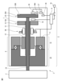
- FIG. 1 is a schematic side view of a position detection system according to a first embodiment of the present disclosure.
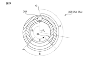
- FIG. 4 is a diagram showing a magnetization pattern in the first embodiment.
- FIG. 2 is a perspective view of a TMR element.
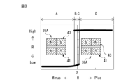
- FIG. 2 is a diagram illustrating the relationship between magnetic field and resistance.
- 6 is a flowchart illustrating calculation of the total rotation of the motor shaft.
- FIG. 11 is a diagram showing a magnetization pattern in a second embodiment.
- FIG. 13 is a schematic side view of a position detection system according to a third embodiment.
- FIG. 2 is an end view showing the rotating disk and stator of the secondary encoder.
- FIG. 6C is a view similar to FIG. 6B with the addition of a rotating disk for the primary encoder.
- FIG. 11 is a schematic side view of a position detection system according to a fourth embodiment of the present disclosure.
- FIG. 1 is a schematic side view of a position detection system based on a first embodiment of the present disclosure.
- the position detection system 5 is incorporated into a machine 3 having a shaft, such as a robot 3.
- a case where the position detection system 5 is incorporated into a robot 3 will be described, but the same applies to a case where the position detection system 5 is incorporated into another machine 3 having a shaft, such as a machine tool.
- the actuator 6 arranged on the link 1 includes a motor 10, for example a servo motor, which are connected to each other, and a reducer 20 coupled to the motor shaft 13 of the motor 10.
- the motor 10 includes a rotor 12 which rotates integrally with the motor shaft 13, and a stator 11 which is arranged to surround the rotor 12.
- the tip of the output shaft 23 of the reducer 20 is connected to the link 2. Therefore, the actuator 6 consisting of the motor 10 and the reducer 20 rotates the link 2 relatively to the link 1 within a predetermined operating range, thereby controlling the positioning.
- the motor shaft 13 is, for example, a hollow shaft, and a primary encoder 15 is attached to its rear end.
- the primary encoder 15 is, for example, an incremental encoder, and outputs A-phase, B-phase, and Z-phase signals.
- the output signals are detected by a detector 16, which detects an absolute position PA1 within one rotation of the motor shaft 13 using a known method.
- the detector 16 includes a circuit for detecting the position PA1.
- the detector 16 may further include a memory, such as a volatile memory or a non-volatile memory, for storing the detected information.
- the detector 16 does not need to be equipped with a circuit for detecting the total number of rotations PB1 of the motor shaft 13.
- the total number of rotations PB1 of the motor shaft 13 can be calculated as described below.
- the output shaft 23 extends through the hollow motor shaft 13 towards the motor 10, and a secondary encoder 25 is attached to the rear end of the output shaft 23.
- the secondary encoder 25 is, for example, an incremental encoder, and outputs A-phase, B-phase and Z-phase signals.
- the output signals are detected by a detector 26, which detects the absolute position PA2 within one rotation of the output shaft 23 using a known method.
- the detector 26 includes a circuit for detecting the absolute position PA2 within one rotation of the output shaft 23.
- the detected information can be stored in a memory within the circuit, for example a volatile memory or a non-volatile memory.
- a total rotation determination circuit 37 connected to a non-rotatably arranged magnetic resistance switch, for example, a TMR (Tunnel Magneto Resistance) element 36A, detects the total number of rotations PB2 of the output shaft 23, particularly the total number of rotations PB2 of the output shaft 23 after being cut off from the main power supply 19. Similarly, the detected information can be stored in a memory of the total rotation determination circuit 37, for example, a volatile memory or a non-volatile memory.
- the total rotation determination circuit 37 is connected to the controller 9 via a calculation unit 38 that calculates the total number of rotations PB1 of the motor shaft 13.
- the primary encoder 15 and the secondary encoder 25 are equipped with rotating disks 15A and 25A, respectively.
- the magnetic resistance switch for example, a TMR element, applies a magnetic flux of a predetermined value or more and switches the resistance value with hysteresis characteristics according to the direction of the magnetic flux.
- the information such as the absolute position PA1, absolute position PA2, and total number of rotations PB2 described above is supplied to a controller 9 that controls the robot 3.
- the controller 9 may be an LSI mounted on the encoders 15 and 25, and the controller 9 may include a memory, such as a volatile memory or a non-volatile memory.
- the controller 9 equipped with a CPU synthesizes the positions using a known method based on the supplied information and drives and controls the motor 10. This performs a positioning operation to position the link 2 at a target position relative to the link 1. Furthermore, the built-in brake 50 provided on the outer surface of the motor shaft 13 is activated in response to an instruction from the controller 9 to brake the motor shaft 13. Furthermore, the controller 9 also serves to supply/cut off electricity to the primary encoder 15 and secondary encoder 25 via the external main power supply 19 when the robot 3 equipped with the links 1 and 2 is in operation.
- a specific magnetization pattern 35B is magnetized on the rotating disk 25A of the secondary encoder 25.
- the magnetization pattern 35B is provided so as to face the TMR element 36A.
- the magnetization pattern 35B may be provided on a rotating disk 35A other than the rotating disk 25A of the secondary encoder 25. In the following, the explanation will be continued assuming that the magnetization pattern 35B is provided on the rotating disk 25A.
- FIG. 2A is a diagram showing the magnetization pattern in the first embodiment.
- the magnetization pattern 35B includes tracks 39 that extend at least partially in the circumferential direction of the rotating disk 25A.
- the track 39 includes a first magnetized sector A that is magnetized so as to switch from one magnetic pole to the other magnetic pole from the inside to the outside in the radial direction of the rotating disk 25A, and a second magnetized sector D that is magnetized so as to switch from the other magnetic pole to one magnetic pole from the inside to the outside in the radial direction of the rotating disk 25A.
- the first magnetized sector A and the second magnetized sector D include a radially inner portion and a radially inner portion of the rotating disk 25A.
- the first magnetized sector A includes a radially inner portion magnetized to a north pole and a radially outer portion magnetized to a south pole.
- the second magnetized sector D includes a radially inner portion magnetized to a south pole and a radially outer portion magnetized to a north pole.
- the magnetic poles of the radially outer portion and the radially inner portion of the first magnetized sector A and the second magnetized sector D are reversed to each other.
- the polarities of the radially inner portion and the radially inner portion of the first magnetized sector A and the polarities of the radially inner portion and the radially inner portion of the second magnetized sector D may be reversed from those described above.
- the first magnetized sector A and the second magnetized sector D are adjacent to each other in the circumferential direction at the origin O of the rotating disk 25A.
- the first magnetized sector A extends from the origin O in a clockwise direction on the rotating disk 25A
- the second magnetized sector D extends from the origin O in a counterclockwise direction on the rotating disk 25A.
- the clockwise direction is defined as the positive direction.
- the first magnetized sector A and the second magnetized sector D extend in opposite directions from the origin O to a position corresponding to an angle of 150°.
- the unmagnetized sectors B and C extend from a position corresponding to an angle of 150° to a position corresponding to an angle of 210°.
- the first magnetized sector A and the second magnetized sector D may extend in opposite directions from the origin O to a position corresponding to an angle of 10° to 30°.
- the non-magnetized sectors B and C may extend from a position corresponding to an angle of 10° to 30° to a position corresponding to an angle of 320° to 350°. In this case, it is possible to increase the detection range, which will be described later.
- FIG. 2B is a perspective view of a TMR element.
- TMR element 36A includes a reference layer 41, a recording layer 43, and an insulating layer 42 disposed between them.
- reference layer 41 a first portion magnetized to an N pole and a second portion magnetized to a S pole are juxtaposed to each other.
- the poles of the first and second portions of reference layer 41 are determined during manufacture, and the poles do not change thereafter. Note that the magnetic poles of the first and second portions may be reversed.
- the TMR element 36A in the initial state, is located at the origin O and at a central position between the radially outer portion and the radially inner portion of the rotating disk 25A. Strictly speaking, in the initial state, the center of the insulating layer 42 of the TMR element 36A is located between the first magnetized sector A and the second magnetized sector D, and between the radially outer portion and the radially inner portion.
- Figure 3 is a diagram showing the relationship between magnetic field and resistance.
- the horizontal axis represents the external magnetic field H acting on the TMR element 36A
- the vertical axis represents the resistance R of the TMR element 36A.
- the TMR element 36A has hysteresis, in which the change in magnetization lags behind the change in the magnetic field.
- the resistance R maintains its original value. In other words, when the TMR element 36A moves relatively from the first magnetized sector A toward the unmagnetized sector B, the resistance R remains low. Furthermore, when the TMR element 36A moves relatively from the second magnetized sector D toward the unmagnetized sector C, the resistance R remains high.
- FIG. 4 is a flow chart explaining the calculation of the total rotation of the motor shaft.
- the operation described in FIG. 4 is performed by the controller 9 when the actuator 6 is disconnected from the main power supply 19 and the motor shaft 13 of the motor 10 and the output shaft 23 of the reducer 20 rotate by inertia and stop.
- the controller 9 operates the total rotation determination circuit 37 and the calculation unit 38 as necessary.
- step S1 the detection unit 26 detects the angle ⁇ s (movement angle) of the output shaft 23 with respect to the origin O. Then, in step S2, the total rotation determination circuit 37 determines in which of sectors A to D on the track 39 the angle ⁇ s is located.
- step S2 If it is determined in step S2 that the angle ⁇ s is in the first magnetized sector A, the process proceeds to step S3.
- step S3 the angle ⁇ s is located in the positive direction, and in this case, the total rotation determination circuit 37 determines that the output shaft 23 is making its second rotation since being disconnected from the main power supply 19.
- step S4 the calculation unit 38 calculates the integer part of "N ⁇ s/360" as the total number of rotations PB1 of the motor shaft 13 after the cutoff. Furthermore, the calculation unit 38 can also calculate the movement angle ⁇ p of the motor shaft 13 during the second rotation of the output shaft 23 as "N ⁇ s".
- step S2 If it is determined in step S2 that the angle ⁇ s is in the second magnetized sector D, the process proceeds to step S5.
- step S5 the angle ⁇ s is in the negative direction, and in this case, the total rotation determination circuit 37 determines that the output shaft 23 is making its first rotation since being disconnected from the main power supply 19.
- step S6 the calculation unit 38 calculates the total number of rotations PB1 of the motor shaft 13 after the cutoff as the integer part of "N ⁇ (360- ⁇ s)/360". Furthermore, the calculation unit 38 can also calculate the movement angle ⁇ p of the motor shaft 13 during the first rotation of the output shaft 23 as "N(360- ⁇ s)".
- step S7 the total rotation determination circuit 37 acquires the resistance R of the TMR element 36A and determines whether the resistance R is greater than a predetermined value R0.
- the predetermined value R0 is a value between the high value (High) and the low value (Low) shown in FIG. 3.
- the total rotation determination circuit 37 determines that the angle ⁇ s is in the non-magnetized sector B, and proceeds to steps S3 and S4. Then, in the same manner as described above, the calculation unit 38 calculates the total number of rotations PB1 of the motor shaft 13, etc.
- the total number of rotations PB1 of the motor shaft 13 and the total number of rotations PB2 of the output shaft 23 can be accurately calculated without power even after the main power supply 19 is cut off.
- FIG. 5 is a diagram showing the magnetization pattern in the second embodiment.
- an additional TMR element 36B (additional magnetic resistance switch) is arranged at a position facing the TMR element 36A in the diametrical direction of the annular magnetization pattern 35B.
- the additional TMR element 36B is arranged facing a rotating disk with the magnetization pattern 35B, for example, rotating disk 25A.
- the track 39 of the magnetization pattern 35B on the rotating disk 25A includes additional unmagnetized sectors E and F.
- the additional unmagnetized sectors E and F are located opposite the unmagnetized sectors B and C in the radial direction of the annular magnetization pattern 35B.
- the additional unmagnetized sectors E and F are located near the origin O.
- the additional unmagnetized sector E is located radially outside the magnetization pattern 35B, and the additional unmagnetized sector F is located radially inside the magnetization pattern 35B.
- the circumferential length of the additional unmagnetized sectors E, F in the magnetization pattern 35B is preferably the same as the circumferential length of the unmagnetized sectors B, C, but may be different.
- the circumferential length of the additional unmagnetized sectors E, F is equal to the circumferential length of the unmagnetized sectors B, C, the unmagnetized sectors B, C and the additional unmagnetized sectors E, F are arranged in positions that are point-symmetrical to each other with respect to the center of the magnetization pattern 35B.
- the center of the insulating layer 42 of the TMR element 36A is located at the center position on the boundary line between unmagnetized sectors E and F, and the center of the insulating layer 42 of the additional TMR element 36B is located at the center position on the boundary line between unmagnetized sectors B and C.
- resistance R and resistance R' have the same value, it is known that some kind of error has occurred.
- Such an error may be, for example, a failure of at least one of TMR element 36A and additional TMR element 36B, and/or the generation of a strong external magnetic field affecting TMR elements 36A and 36B. Therefore, in the second embodiment, it is possible to detect, via controller 9, that TMR elements 36A and 36B have failed, that a strong external magnetic field is being generated, etc.
- FIG. 6A is a schematic side view of a position detection system based on a third embodiment.
- An extension 23a for example a hollow tube, is connected to the output shaft 23 of the reducer 20, and this extension 23a passes through the hollow motor shaft 13 and extends to the motor 10 side.
- the output shaft 23 of the reducer 20 and the extension 23a may be formed integrally.
- the extension 23a may be a part of the output shaft 23. Therefore, hereinafter, the "extension 23a" may be expressed as the "output section 23".
- a circular first support member 18 extending in the radial direction is attached to the rear end of the motor shaft 13.
- the first support member 18 is provided with an annular protrusion 18a, which preferably engages with the rear end of the motor shaft 13.
- the radially outer portion of the first support member 18 extends in the axial direction of the motor shaft 13 so as to be spaced away from the motor 10.
- a rotating disk 15A for the primary encoder 15 is provided on the rear end surface of the portion extending in the axial direction. In other words, the rotating disk 15A is supported by a portion of the first support member 18.
- a cylindrical extension member 71 is attached to the rear end of the housing 10a of the actuator 6.
- the rear end face of the extension member 71 extends radially inward.
- a second support member 28 is attached via a bearing 79 to the inner circumferential surface of the portion extending radially inward.
- the inner diameter of the second support member 28 is approximately equal to the inner diameter of the extension portion 23a.
- the substrate 42a which includes the detection unit 16, the detection unit 26, and the TMR element 36A, is attached to the inner circumferential surface of the extension member 71.
- the second support member 28 extends from the rear end of the actuator 6 towards the reducer 20, and the tip of the portion extending towards the reducer 20 extends radially outward.
- a rotating disk 25A for the secondary encoder 25 is provided on the rear end surface of the portion extending radially outward. In other words, the rotating disk 25A is supported by a portion of the second support member 28.
- FIG. 6B is an end view showing the rotating disk and stator of the secondary encoder.
- the rotating disk 25A for the secondary encoder 25 supported by the second support member 28 is aligned to the origin position.
- a marker provided in advance on the stator 11 is aligned with a marker provided in advance on the rotating disk 25A.
- these markers are preferably triangular, for example.
- the rotating disk 15A for the primary encoder 15 is attached to the rear end of the motor shaft 13 via the first support member 18.
- the mounting position (phase) of the rotating disk 15A can be arbitrary.
- the extension member 71 equipped with the substrate 42a is attached to the housing 10a.
- the positions within one rotation of the rotating disks 15A and 25A are detected by the detectors 16 and 26, respectively, and the absolute positions of the rotating disks 15A and 25A are stored in the memory described above as offset amounts. In this way, after the rotating disks 15A and 25A have been installed and the phase of the motor shaft 13 is stopped at its origin position, the absolute positions within one rotation of the rotating disks 15A and 25A are recorded in the memory as error amounts. This allows the position detection system 5a to be made available for use sooner.
- FIG. 7 is a schematic side view of a position detection system based on a fourth embodiment of the present disclosure.
- a new rotating disk 35A is provided coaxially with the rotating disk 25A. It is preferable that the rotating disk 35A is provided so that the rotating disk 25A is disposed between the rotating disk 35A and the rotating disk 15A.
- the rotating disk 35A is provided at the tip of the output shaft 23 that passes through the rotating disk 25A. Therefore, the rotating disk 35A rotates together with the rotating disk 25A.
- a magnetization pattern 35B similar to that described above is provided on the rotating disk 35A, and no magnetization pattern 35B is provided on the rotating disk 25A. Therefore, the TMR element 36A is positioned so that it faces the magnetization pattern 35B of the rotating disk 35A.
- the fourth embodiment has the additional effect of allowing the rotating disk 35A and TMR element 36A to be retrofitted to an existing position detection system.
- the position detection system 5 in the first embodiment has the advantage of being smaller and lighter than the position detection system 5' that requires a rotating disk 35A, etc.
- the total number of rotations PB1 of the motor shaft 13 can be accurately calculated without power even after the main power supply 19 is cut off.
- a primary encoder for detecting an absolute angle within one rotation of a motor shaft of a motor for detecting an absolute angle within one rotation of an output shaft of a reducer coupled to the motor;
- the secondary encoder includes: A total rotation determination circuit is included which calculates the total number of rotations of the output shaft, The total rotation determination circuit includes: a rotating disk magnetized with a specific magnetization pattern and rotating coaxially with the output shaft; a magnetic resistance switch disposed opposite the rotating disk, for applying a magnetic flux of a predetermined value or more to the magnetic resistance switch and for switching a resistance value with a hysteresis characteristic according to the direction of the magnetic flux; 1.
- the first magnetization sector is provided in an area of the track at an angle of (360- ⁇ s) degrees or less around the output axis
- the second magnetization sector is provided in an area having an angle of ⁇ (360 ⁇ s) degrees or less around the output axis, 5.
- the position detection system of claim 4, wherein the unmagnetized sector is provided in an area of the track at an angle of ⁇ ( ⁇ s-180) degrees or more around the output axis.
- a calculation unit is provided, When the position of the output shaft is ⁇ s and the reduction ratio of the reducer is 1/N, the calculation unit calculates the movement angle ⁇ p of the motor shaft when the output shaft makes a first rotation as “N(360 ⁇ s)” and calculates the movement angle ⁇ p of the motor shaft when the output shaft makes a second rotation as “N ⁇ s”,
- the position detection system according to any one of appendixes 1 to 5, wherein the calculation unit calculates the integer part of "N(360- ⁇ s)/360" during the first rotation of the output shaft as the total number of rotations of the motor shaft, and calculates the integer part of "N ⁇ s/360” during the second rotation of the output shaft as the total number of rotations of the motor shaft.
- the track includes a first magnetized sector that is magnetized to switch from one magnetic pole to the other magnetic pole from the inside to the outside in the radial direction of the rotating disk, a second magnetized sector that is magnetized to switch from the other magnetic pole to the one magnetic pole from the inside to the outside in the radial direction of the rotating disk, and a non-magnetized sector that is not magnetized.
- the first magnetization sector is provided in an area of the track at an angle of (360- ⁇ s) degrees or less around the output axis
- the second magnetization sector is provided in an area having an angle of ⁇ (360 ⁇ s) degrees or less around the output axis, 12.
- the actuator of claim 11, wherein the unmagnetized sector is provided in an area of the track at an angle of ⁇ ( ⁇ s-180) degrees or more around the output axis.
- a calculation unit is provided, When the position of the output shaft is ⁇ s and the reduction ratio of the reducer is 1/N, the calculation unit calculates the movement angle ⁇ p of the motor shaft when the output shaft makes a first rotation as “N(360 ⁇ s)” and calculates the movement angle ⁇ p of the motor shaft when the output shaft makes a second rotation as “N ⁇ s”, 12.
- the actuator according to any one of Appendices 8 to 11, wherein the calculation unit calculates the integer part of "N(360- ⁇ s)/360" during a first rotation of the output shaft as a total rotation number of the motor shaft, and calculates the integer part of "N ⁇ s/360" during a second rotation of the output shaft as a total rotation number of the motor shaft.
Landscapes
- Physics & Mathematics (AREA)
- General Physics & Mathematics (AREA)
- Transmission And Conversion Of Sensor Element Output (AREA)
Abstract
Description
(付記1)
モータのモータ軸の一回転内の絶対角度を検出するプライマリエンコーダと、
前記モータに結合された減速機の出力軸の一回転内の絶対角度を検出するセカンダリエンコーダと、を具備し、
前記セカンダリエンコーダは、
前記出力軸の総回転回数を計算する総回転判定回路を含んでおり、
該総回転判定回路は、
特定の磁化パターンに着磁されていて前記出力軸と同軸で回転する回転ディスクと、
前記回転ディスクに対面して配置されていて所定値以上の磁束を印加し、その磁束の向きに応じて抵抗値をヒステリシス特性を持って切り替える磁気抵抗スイッチと、
を含む、位置検出システム。
(付記2)
前記磁気抵抗スイッチは、TMR素子である、付記1に記載の位置検出システム。
(付記3)
前記回転ディスクは、前記セカンダリエンコーダの回転ディスクである、付記1または2に記載の位置検出システム。
(付記4)
前記回転ディスクの表面には、前記特定の磁化パターンに着磁されていて前記回転ディスクの周方向に少なくとも部分的に延びるトラックが設けられており、
前記トラックは、前記回転ディスクの半径方向内側から外側に向かって一方の磁極から他方の磁極に切替わるよう磁化された第一磁化セクタと、前記回転ディスクの半径方向内側から外側に向かって前記他方の磁極から前記一方の磁極に切替わるよう磁化された第二磁化セクタと、磁化されていない無磁化セクタとを含む、付記1から3のいずれかに記載の位置検出システム。
(付記5)
前記出力軸の移動角を前記トラックの原点に対して±θs度とするとき、
前記第一磁化セクタは、前記出力軸周りにおける「(360-θs)」度以下の角度の前記トラックの領域に設けられており、
前記第二磁化セクタは、前記出力軸周りにおける「-(360-θs)」度以下の角度の領域に設けられており、
前記無磁化セクタは、前記出力軸周りにおける±(θs-180)度以上の角度の前記トラックの領域に設けられている、付記4に記載の位置検出システム。
(付記6)
さらに、計算部を具備し、
前記出力軸の位置をθs、前記減速機の減速比を1/Nとした場合に、前記計算部は、前記出力軸が1回転目における前記モータ軸の移動角θpを「N(360-θs)」として算出し、前記出力軸が2回転目における前記モータ軸の移動角θpを「Nθs」として算出し、
前記計算部は、前記出力軸が1回転目における「N(360-θs)/360」の整数部分を前記モータ軸の総回転回数として算出すると共に、前記出力軸が2回転目における「Nθs/360」の整数部分を前記モータ軸の総回転回数として算出する、付記1から5のいずれかに記載の位置検出システム。
(付記7)
前記磁気抵抗スイッチに対して前記回転ディスクの直径方向反対側において、前記回転ディスクに対面して配置された追加の磁気抵抗スイッチを含み、
前記トラックは、前記無磁化セクタに対して前記回転ディスクの直径方向反対側に設けられた追加の無磁化セクタを含む、付記4に記載の位置検出システム。
(付記8)
モータと、
該モータに結合された減速機と、
前記モータのモータ軸の一回転内の絶対角度を検出するプライマリエンコーダと、
前記減速機の出力軸の一回転内の絶対角度を検出するセカンダリエンコーダと、を具備し、
前記セカンダリエンコーダは、前記出力軸の総回転を計算する総回転判定回路を含んでおり、
該総回転判定回路は、
特定の磁化パターンに着磁されていて前記出力軸と同軸で回転する回転ディスクと、
前記回転ディスクに対面して配置されていて所定値以上の磁束を印加し、その磁束の向きに応じて抵抗値をヒステリシス特性を持って切り替える磁気抵抗スイッチと、
を含む、アクチュエータ。
(付記9)
前記磁気抵抗スイッチは、TMR素子である、付記8に記載のアクチュエータ。
(付記10)
前記回転ディスクは、前記セカンダリエンコーダの回転ディスクである、付記8または9に記載のアクチュエータ。
(付記11)
前記回転ディスクの表面には、前記特定の磁化パターンに着磁されていて前記回転ディスクの周方向に少なくとも部分的に延びるトラックが設けられており、
前記トラックは、前記回転ディスクの半径方向内側から外側に向かって一方の磁極から他方の磁極に切替わるよう磁化された第一磁化セクタと、前記回転ディスクの半径方向内側から外側に向かって前記他方の磁極から前記一方の磁極に切替わるよう磁化された第二磁化セクタと、磁化されていない無磁化セクタとを含む、付記8から9のいずれかに記載のアクチュエータ。
(付記12)
前記出力軸の移動角を前記トラックの原点に対して±θs度とするとき、
前記第一磁化セクタは、前記出力軸周りにおける「(360-θs)」度以下の角度の前記トラックの領域に設けられており、
前記第二磁化セクタは、前記出力軸周りにおける「-(360-θs)」度以下の角度の領域に設けられており、
前記無磁化セクタは、前記出力軸周りにおける±(θs-180)度以上の角度の前記トラックの領域に設けられている、付記11に記載のアクチュエータ。
(付記13)
さらに、計算部を具備し、
前記出力軸の位置をθs、前記減速機の減速比を1/Nとした場合に、前記計算部は、前記出力軸が1回転目における前記モータ軸の移動角θpを「N(360-θs)」として算出し、前記出力軸が2回転目における前記モータ軸の移動角θpを「Nθs」として算出し、
前記計算部は、前記出力軸が1回転目における「N(360-θs)/360」の整数部分を前記モータ軸の総回転回数として算出すると共に、前記出力軸が2回転目における「Nθs/360」の整数部分を前記モータ軸の総回転回数として算出する、付記8から11のいずれかに記載のアクチュエータ。
(付記14)
前記磁気抵抗スイッチに対して前記回転ディスクの直径方向反対側において、前記回転ディスクに対面して配置された追加の磁気抵抗スイッチを含み、
前記トラックは、前記無磁化セクタに対して前記回転ディスクの直径方向反対側に設けられた追加の無磁化セクタを含む、付記11に記載のアクチュエータ。
5、5a、5’ 位置検出システム
6 アクチュエータ
9 コントローラ
10 モータ
10a ハウジング
11 ステータ
12 ロータ
13 モータ軸
15 プライマリエンコーダ
15A、25A、35A 回転ディスク
16 検出部
19 主電源
20 減速機
23 出力軸
25 セカンダリエンコーダ
26 検出部
35B 磁化パターン
36A、36B TMR素子(磁気抵抗スイッチ)
37 総回転判定回路
38 計算部
39 トラック
41 参照層
42 絶縁層
42a 基板
43 記録層
A 第一磁化セクタ
B、C、E、F 無磁化セクタ
D 第二磁化セクタ
Claims (14)
- モータのモータ軸の一回転内の絶対角度を検出するプライマリエンコーダと、
前記モータに結合された減速機の出力軸の一回転内の絶対角度を検出するセカンダリエンコーダと、を具備し、
前記セカンダリエンコーダは、
前記出力軸の総回転回数を計算する総回転判定回路を含んでおり、
該総回転判定回路は、
特定の磁化パターンに着磁されていて前記出力軸と同軸で回転する回転ディスクと、
前記回転ディスクに対面して配置されていて所定値以上の磁束を印加し、その磁束の向きに応じて抵抗値をヒステリシス特性を持って切り替える磁気抵抗スイッチと、
を含む、位置検出システム。 - 前記磁気抵抗スイッチは、TMR素子である、請求項1に記載の位置検出システム。
- 前記回転ディスクは、前記セカンダリエンコーダの回転ディスクである、請求項1に記載の位置検出システム。
- 前記回転ディスクの表面には、前記特定の磁化パターンに着磁されていて前記回転ディスクの周方向に少なくとも部分的に延びるトラックが設けられており、
前記トラックは、前記回転ディスクの半径方向内側から外側に向かって一方の磁極から他方の磁極に切替わるよう磁化された第一磁化セクタと、前記回転ディスクの半径方向内側から外側に向かって前記他方の磁極から前記一方の磁極に切替わるよう磁化された第二磁化セクタと、磁化されていない無磁化セクタとを含む、請求項1に記載の位置検出システム。 - 前記出力軸の移動角を前記トラックの原点に対して±θs度とするとき、
前記第一磁化セクタは、前記出力軸周りにおける「(360-θs)」度以下の角度の前記トラックの領域に設けられており、
前記第二磁化セクタは、前記出力軸周りにおける「-(360-θs)」度以下の角度の領域に設けられており、
前記無磁化セクタは、前記出力軸周りにおける±(θs-180)度以上の角度の前記トラックの領域に設けられている、請求項4に記載の位置検出システム。 - さらに、計算部を具備し、
前記出力軸の位置をθs、前記減速機の減速比を1/Nとした場合に、前記計算部は、前記出力軸が1回転目における前記モータ軸の移動角θpを「N(360-θs)」として算出し、前記出力軸が2回転目における前記モータ軸の移動角θpを「Nθs」として算出し、
前記計算部は、前記出力軸が1回転目における「N(360-θs)/360」の整数部分を前記モータ軸の総回転回数として算出すると共に、前記出力軸が2回転目における「Nθs/360」の整数部分を前記モータ軸の総回転回数として算出する、請求項1に記載の位置検出システム。
- 前記磁気抵抗スイッチに対して前記回転ディスクの直径方向反対側において、前記回転ディスクに対面して配置された追加の磁気抵抗スイッチを含み、
前記トラックは、前記無磁化セクタに対して前記回転ディスクの直径方向反対側に設けられた追加の無磁化セクタを含む、請求項4に記載の位置検出システム。 - モータと、
該モータに結合された減速機と、
前記モータのモータ軸の一回転内の絶対角度を検出するプライマリエンコーダと、
前記減速機の出力軸の一回転内の絶対角度を検出するセカンダリエンコーダと、を具備し、
前記セカンダリエンコーダは、前記出力軸の総回転を計算する総回転判定回路を含んでおり、
該総回転判定回路は、
特定の磁化パターンに着磁されていて前記出力軸と同軸で回転する回転ディスクと、
前記回転ディスクに対面して配置されていて所定値以上の磁束を印加し、その磁束の向きに応じて抵抗値をヒステリシス特性を持って切り替える磁気抵抗スイッチと、
を含む、アクチュエータ。 - 前記磁気抵抗スイッチがTMR素子である、請求項8に記載のアクチュエータ。
- 前記回転ディスクは、前記セカンダリエンコーダの回転ディスクである、請求項8に記載のアクチュエータ。
- 前記回転ディスクの表面には、前記特定の磁化パターンに着磁されていて前記回転ディスクの周方向に少なくとも部分的に延びるトラックが設けられており、
前記トラックは、前記回転ディスクの半径方向内側から外側に向かって一方の磁極から他方の磁極に切替わるよう磁化された第一磁化セクタと、前記回転ディスクの半径方向内側から外側に向かって前記他方の磁極から前記一方の磁極に切替わるよう磁化された第二磁化セクタと、磁化されていない無磁化セクタとを含む、請求項8に記載のアクチュエータ。 - 前記出力軸の移動角を前記トラックの原点に対して±θs度とするとき、
前記第一磁化セクタは、前記出力軸周りにおける「(360-θs)」度以下の角度の前記トラックの領域に設けられており、
前記第二磁化セクタは、前記出力軸周りにおける「-(360-θs)」度以下の角度の領域に設けられており、
前記無磁化セクタは、前記出力軸周りにおける±(θs-180)度以上の角度の前記トラックの領域に設けられている、請求項100に記載のアクチュエータ。 - さらに、計算部を具備し、
前記出力軸の位置をθs、前記減速機の減速比を1/Nとした場合に、前記計算部は、前記出力軸が1回転目における前記モータ軸の移動角θpを「N(360-θs)」として算出し、前記出力軸が2回転目における前記モータ軸の移動角θpを「Nθs」として算出し、
前記計算部は、前記出力軸が1回転目における「N(360-θs)/360」の整数部分を前記モータ軸の総回転回数として算出すると共に、前記出力軸が2回転目における「Nθs/360」の整数部分を前記モータ軸の総回転回数として算出する、請求項10に記載のアクチュエータ。 - 前記磁気抵抗スイッチに対して前記回転ディスクの直径方向反対側において、前記回転ディスクに対面して配置された追加の磁気抵抗スイッチを含み、
前記トラックは、前記無磁化セクタに対して前記回転ディスクの直径方向反対側に設けられた追加の無磁化セクタを含む、請求項10に記載のアクチュエータ。
Priority Applications (5)
| Application Number | Priority Date | Filing Date | Title |
|---|---|---|---|
| CN202380098833.3A CN121219551A (zh) | 2023-06-05 | 2023-06-05 | 位置检测系统以及致动器 |
| JP2025525435A JPWO2024252459A1 (ja) | 2023-06-05 | 2023-06-05 | |
| PCT/JP2023/020800 WO2024252459A1 (ja) | 2023-06-05 | 2023-06-05 | 位置検出システムおよびアクチュエータ |
| DE112023006075.4T DE112023006075T5 (de) | 2023-06-05 | 2023-06-05 | Positionsdetektionssystem und Aktuator |
| TW113116623A TW202449360A (zh) | 2023-06-05 | 2024-05-06 | 位置檢測系統及致動器 |
Applications Claiming Priority (1)
| Application Number | Priority Date | Filing Date | Title |
|---|---|---|---|
| PCT/JP2023/020800 WO2024252459A1 (ja) | 2023-06-05 | 2023-06-05 | 位置検出システムおよびアクチュエータ |
Publications (1)
| Publication Number | Publication Date |
|---|---|
| WO2024252459A1 true WO2024252459A1 (ja) | 2024-12-12 |
Family
ID=93795218
Family Applications (1)
| Application Number | Title | Priority Date | Filing Date |
|---|---|---|---|
| PCT/JP2023/020800 Ceased WO2024252459A1 (ja) | 2023-06-05 | 2023-06-05 | 位置検出システムおよびアクチュエータ |
Country Status (5)
| Country | Link |
|---|---|
| JP (1) | JPWO2024252459A1 (ja) |
| CN (1) | CN121219551A (ja) |
| DE (1) | DE112023006075T5 (ja) |
| TW (1) | TW202449360A (ja) |
| WO (1) | WO2024252459A1 (ja) |
Citations (5)
| Publication number | Priority date | Publication date | Assignee | Title |
|---|---|---|---|---|
| WO2007046182A1 (ja) * | 2005-10-18 | 2007-04-26 | Harmonic Drive Systems Inc. | ギヤ付きモータの多回転絶対値エンコーダ |
| JP2008039737A (ja) * | 2006-08-10 | 2008-02-21 | Yaskawa Electric Corp | 多回転量算出方法、バッテリーレス多回転式絶対値エンコーダ装置およびこれを用いた減速機付アクチュエータ |
| JP2013538349A (ja) * | 2010-08-24 | 2013-10-10 | ムービング マグネット テクノロジーズ (ソシエテ アノニム) | 磁気多回転絶対位置検出装置 |
| JP2016503174A (ja) * | 2013-01-11 | 2016-02-01 | 江▲蘇▼多▲維▼科技有限公司Multidimension Technology Co., Ltd. | マルチターンアブソリュート磁気エンコーダ |
| JP2016124094A (ja) * | 2015-01-08 | 2016-07-11 | ファナック株式会社 | 複数の回転角検出器により回転角を更新するロボット制御装置 |
-
2023
- 2023-06-05 CN CN202380098833.3A patent/CN121219551A/zh active Pending
- 2023-06-05 DE DE112023006075.4T patent/DE112023006075T5/de active Pending
- 2023-06-05 WO PCT/JP2023/020800 patent/WO2024252459A1/ja not_active Ceased
- 2023-06-05 JP JP2025525435A patent/JPWO2024252459A1/ja active Pending
-
2024
- 2024-05-06 TW TW113116623A patent/TW202449360A/zh unknown
Patent Citations (5)
| Publication number | Priority date | Publication date | Assignee | Title |
|---|---|---|---|---|
| WO2007046182A1 (ja) * | 2005-10-18 | 2007-04-26 | Harmonic Drive Systems Inc. | ギヤ付きモータの多回転絶対値エンコーダ |
| JP2008039737A (ja) * | 2006-08-10 | 2008-02-21 | Yaskawa Electric Corp | 多回転量算出方法、バッテリーレス多回転式絶対値エンコーダ装置およびこれを用いた減速機付アクチュエータ |
| JP2013538349A (ja) * | 2010-08-24 | 2013-10-10 | ムービング マグネット テクノロジーズ (ソシエテ アノニム) | 磁気多回転絶対位置検出装置 |
| JP2016503174A (ja) * | 2013-01-11 | 2016-02-01 | 江▲蘇▼多▲維▼科技有限公司Multidimension Technology Co., Ltd. | マルチターンアブソリュート磁気エンコーダ |
| JP2016124094A (ja) * | 2015-01-08 | 2016-07-11 | ファナック株式会社 | 複数の回転角検出器により回転角を更新するロボット制御装置 |
Also Published As
| Publication number | Publication date |
|---|---|
| JPWO2024252459A1 (ja) | 2024-12-12 |
| TW202449360A (zh) | 2024-12-16 |
| CN121219551A (zh) | 2025-12-26 |
| DE112023006075T5 (de) | 2026-01-22 |
Similar Documents
| Publication | Publication Date | Title |
|---|---|---|
| JP6658208B2 (ja) | モータシステム | |
| JP7489583B2 (ja) | 回転検出器及びそれを備えたモータ | |
| US6720763B1 (en) | Compact rotary magnetic position sensor having a sinusoidally varying output | |
| US6329782B1 (en) | Method and apparatus for robust generation of an index pulse for an electric power steering system | |
| WO2009125527A1 (ja) | ブラシレスモータ位置検出装置 | |
| JP4999395B2 (ja) | レンジ切換機構の制御装置 | |
| WO2005124285A1 (ja) | 磁気式エンコーダ装置 | |
| JP2004343987A (ja) | 回動駆動装置 | |
| JP4519750B2 (ja) | 回転角度検出装置 | |
| WO2024252459A1 (ja) | 位置検出システムおよびアクチュエータ | |
| JP5315212B2 (ja) | 回転角度センサ異常検出装置、モータ制御システム、電動パワーステアリング | |
| JP2009069092A (ja) | 回転検出装置および回転検出装置付き軸受 | |
| JP6970727B2 (ja) | 角度センサーの補正方法及び角度センサーの補正装置 | |
| JP6166088B2 (ja) | 電磁サスペンション装置 | |
| JP4189953B2 (ja) | 位置切換制御装置 | |
| JP2018197738A (ja) | 角度検出装置、相対角度検出装置、トルクセンサ、電動パワーステアリング装置及び車両 | |
| JP2011112438A (ja) | エンコーダ | |
| WO2021145460A1 (ja) | アブソリュートエンコーダ | |
| CN120344787A (zh) | 挡位诊断方法、换挡控制装置和记录有计算机程序的记录介质 | |
| JP4941378B2 (ja) | 回転角検出装置 | |
| JP6052971B2 (ja) | 同期電動機制御装置及び同期電動機制御方法 | |
| JP2007135258A (ja) | ステッピングモータ制御装置とアクチュエータ | |
| JP2015120230A (ja) | ロボットハンド | |
| JP4383231B2 (ja) | 非接触型位置センサ | |
| TWI553298B (zh) | Rotation angle protection device |
Legal Events
| Date | Code | Title | Description |
|---|---|---|---|
| 121 | Ep: the epo has been informed by wipo that ep was designated in this application |
Ref document number: 23940567 Country of ref document: EP Kind code of ref document: A1 |
|
| ENP | Entry into the national phase |
Ref document number: 2025525435 Country of ref document: JP Kind code of ref document: A |
|
| WWE | Wipo information: entry into national phase |
Ref document number: 2025525435 Country of ref document: JP |
|
| WWE | Wipo information: entry into national phase |
Ref document number: 112023006075 Country of ref document: DE |
|
| WWP | Wipo information: published in national office |
Ref document number: 112023006075 Country of ref document: DE |