WO2024252444A1 - 判定システム、判定方法、及び判定プログラム - Google Patents
判定システム、判定方法、及び判定プログラム Download PDFInfo
- Publication number
- WO2024252444A1 WO2024252444A1 PCT/JP2023/020753 JP2023020753W WO2024252444A1 WO 2024252444 A1 WO2024252444 A1 WO 2024252444A1 JP 2023020753 W JP2023020753 W JP 2023020753W WO 2024252444 A1 WO2024252444 A1 WO 2024252444A1
- Authority
- WO
- WIPO (PCT)
- Prior art keywords
- unit
- referee
- event
- umpire
- video
- Prior art date
- Legal status (The legal status is an assumption and is not a legal conclusion. Google has not performed a legal analysis and makes no representation as to the accuracy of the status listed.)
- Pending
Links
Images


Classifications
-
- G—PHYSICS
- G06—COMPUTING OR CALCULATING; COUNTING
- G06T—IMAGE DATA PROCESSING OR GENERATION, IN GENERAL
- G06T7/00—Image analysis
- G06T7/20—Analysis of motion
Definitions
- the present invention relates to a judgment system, a judgment method, and a judgment program.
- Patent document 1 discloses a system for automatically detecting umpire decisions during a ball game, which analyzes an image showing a second event that occurs after a first event that is suspected to be an event based on a specified rule based on the rules of a given ball game, and determines the umpire's decision related to whether the first event is an event based on the specified rule.
- Patent Document 1 describes that, for example, in soccer, if a goal event is detected as the first event, and then a second event in which the ball is set on the center spot is detected, it is determined that the goal of the first event is the final decision.
- the present invention was made in consideration of the above-mentioned problems, and aims to provide a judging system that can correctly recognize the decisions made by umpires.
- a judging system is a judging system for judging events defined by the competition rules, and is equipped with a video acquisition unit for acquiring video of a referee captured by a filming unit, or a detection information acquisition unit for acquiring detection information relating to the actions or state of the referee detected by a referee-worn system worn or held by the referee, or both the video acquisition unit and the detection information acquisition unit, a gesture identification unit for identifying a gesture of the referee based on the video of the referee captured by the video acquisition unit, or the detection information acquired by the detection information acquisition unit, or the video of the referee and the detection information, and an event judgment unit for judging an event defined by the competition rules based on the gesture.
- the umpire wearing system may be equipped with at least one of a sensor that detects the movement of the umpire's arm, a sensor that detects the movement of the flag held by the umpire, a sensor that detects the use of a whistle, and a switch input unit that accepts switch input of the flag.
- the system may further include a trigger determination unit that determines whether a trigger for the determination process executed by the gesture identification unit and the event determination unit is detected based on at least one of the video of the referee and the detection information, and the trigger may be a predetermined action of the referee that can be reasonably determined to have caused the event to occur.
- the umpires include the chief umpire and the assistant umpire.
- the trigger determination unit may determine, as the trigger, at least one of the use of a whistle by the referee and the use of a flag by the assistant referee.
- the gesture identification unit may identify the gestures of the referee and the assistant referee, the candidate extraction unit may extract event candidates based on the gestures of the referee and the assistant referee, and the event determination unit may determine an event defined in the competition rules from the event candidates based on the gestures of the referee.
- the system may further include an audio information acquisition unit that acquires audio information of the referee, and the candidate extraction unit may further extract candidates for events defined in the competition rules based on the audio information of the referee, and the event determination unit may determine the events defined in the competition rules based on the candidate events.
- the system may further include a shooting control command unit that controls changes to at least one of the position of the shooting unit, the shooting direction, the shooting subject, and the zoom amount in response to the determined event.
- a shooting control command unit that controls changes to at least one of the position of the shooting unit, the shooting direction, the shooting subject, and the zoom amount in response to the determined event.
- the device may further include a distribution control unit that distributes or transmits information related to the determined event together with the video captured by the image capture unit to a specified terminal.
- the image capture unit may be configured to include multiple image capture units, and the distribution control unit may switch the image to be distributed to the specified terminal from the image captured by one image capture unit to the image captured by another image capture unit depending on the determined event.
- the device may further include a status display unit that displays, on the specified terminal, the status of the determination process executed by the gesture identification unit and the event determination unit.
- the device may further include a specified terminal that distributes the image from the image capture unit, and an event candidate display unit that displays candidates for the event on the specified terminal during the determination process executed by the gesture identification unit and the event determination unit.
- the photographing unit may be a camera mounted on an aircraft flying above and around the photographing area, a photographing camera mounted on an aircraft flying above or around the photographing area, a photographing camera movably arranged around the photographing area, a photographing camera fixedly arranged around the photographing area, or a combination of these.
- a judging method is a judging method for judging an event defined as a competition rule, in which a computer executes an image acquisition process for acquiring an image of the referee captured by a camera unit, a gesture identification process for identifying a gesture of the referee based on the image of the referee captured by the image acquisition process, and an event judgment process for judging an event defined in the competition rule based on the gesture.
- a computer program is a judgment program for judging events defined as competition rules, which causes a computer to execute a video acquisition process for acquiring video of a referee captured by a camera unit, a gesture identification process for identifying a gesture of the referee based on the video of the referee captured by the video acquisition process, and an event judgment process for judging an event defined by the competition rules based on the gesture.
- computer programs can be provided by being stored on various data-readable recording media, or by being made available for download via a network such as the Internet.
- the present invention allows the umpire to correctly recognize the most common decisions made.
- FIG. 1 is an overall configuration diagram of a determination system according to an embodiment of the present invention
- FIG. 2 is a diagram illustrating stakeholders related to the determination system of the embodiment.
- FIG. 2 is a simplified external perspective view of the drone according to the embodiment.
- FIG. 2 is a functional configuration diagram of the drone according to the embodiment.
- FIG. 2 is a schematic diagram showing a stadium, which is an example of a subject area to be photographed.
- FIG. 2 is a simplified external perspective view of the mobile camera according to the embodiment.
- FIG. 2 is a functional configuration diagram of the mobile camera according to the embodiment.
- FIG. 2 is a simplified external perspective view of the fixed camera according to the embodiment.
- FIG. 2 is a functional configuration diagram of the fixed camera according to the embodiment.
- FIG. 2 is a functional configuration diagram of the control device according to the embodiment.
- FIG. 2 is a functional configuration diagram of the referee wearing system of the embodiment.
- FIG. 2 is a functional configuration diagram of the competition official terminal device according to the embodiment.
- FIG. 4 is a functional configuration diagram of the competition team staff terminal device according to the embodiment.
- FIG. 13 is a diagram showing the contents of a correspondence table that stores the correspondence between gestures of an assistant referee and events.
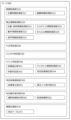
- FIG. 5A and 5B are diagrams showing examples of screens displayed on a terminal of the determination system, in which (a) is a screen displaying a determination result, and (b) is a screen displaying a determination status.
- This is a schematic diagram showing how photography is controlled in accordance with the output of a predetermined judgment result when the area to be photographed is photographed by a drone, and shows (a) the drone's position and photography area before the predetermined judgment result is output, and (b) the drone's position and photography area after the predetermined judgment result is output.
- FIG. 1 is a schematic diagram showing how photography is controlled in response to the output of a predetermined judgment result when the area to be photographed is photographed by a mobile camera, showing (a) the photography area before the predetermined judgment result is output, and (b) the photography area after the predetermined judgment result has been output.
- FIG. 2 is a process flow diagram showing an overall picture of the process executed by the determination system 1 of the embodiment.
- a process flow diagram showing the flow of the process of acquiring image and detection information of a referee, among the processes executed by the judgment system 1 of the embodiment.
- 10 is a process flow diagram showing the flow of a process for identifying a gesture of a referee, among the processes executed by the judgment system 1 of the embodiment.
- FIG. 10 is a process flow diagram showing a flow of a process for finalizing a judgment result among the processes executed by the judgment system 1 of the embodiment.
- A. One embodiment [A-1. Configuration] (A-1-1. Stakeholders)
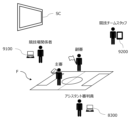
- a determination system 1 (hereinafter also referred to as "system 1") according to one embodiment of the present invention photographs a competition taking place in a stadium F (an example of a "photographed area” described later) or an event taking place at an event venue with a drone 100, and determines the behavior, state, or event of a specific subject of photography that occurs during the competition or event from the gestures, etc. of the specific subject of photography.
- “gesture” is interpreted to include not only gestures and hand movements defined in advance by a person, but also simple body movements.
- the drone 100 is an example of photographing equipment 1000 that photographs the stadium F, and in the following description, the drone 100, the mobile camera 710, or the fixed camera 720 may be collectively referred to as the "photography equipment 1000.”
- Figure 2 shows the stakeholders that appear in the scenario in which system 1 is operated.
- the example in this figure shows the case in which system 1 is applied to a soccer game, and mainly includes referees, officials in the game, and team staff. Note that in the following explanation, we will use an example of system 1 that targets soccer as a shooting subject as necessary, but system 1 can also be applied to sports and events other than soccer.
- the referees are the people who watch the progress of the game in and around the playing field F, make decisions in accordance with the rules of the game, and ensure the success of the game.
- the refereeing staff consists of at least one referee and two assistant referees (also called linesmen), and may also include assistant referees depending on the way the game is run.
- the referee enforces the rules of the game and has all the authority within the scope of the rules of the game, including making the final decisions.
- Two assistant referees, one on each side are stationed outside the touchlines F111a and F111b (see Figure 5) of the playing field F to assist the referee.
- the assistant referees also known as VAR (Video Assistant Referee), assist the referee from outside the playing field F by checking the video footage captured by the video capture device 1000, providing the referee with information based on the footage, and proposing review of decisions.
- Those involved in the competition are those who are involved in the competition in a third-party capacity, separate from the members and staff of the competing teams, and include, for example, facilities personnel who manage the facilities within the competition venue F, video distributors who distribute the images displayed on the competition venue screen SC installed in the competition venue F, commentators for the competition, operators of the competition venue F, operators of the system 1, etc.
- video distributors may also distribute images to terminals prepared for commentators, distribute live images via an internetwork, etc., broadcast over radio waves, and may also edit the content of the distribution and switch images as appropriate.
- Competition team staff are people associated with the competing teams in a competition, such as managers, coaches, and technical staff, and generally sit on the bench and are directly involved in the competition.
- the system 1 applied to soccer games identifies the gesture of a referee associated with the occurrence of an event based on the video and action information of the referee, and determines whether the referee is The content of the decision or the event indicated by the decision made by the referee is determined, and the decision result is output.
- the target shooting area for example a stadium F, refers to a two-dimensional area to be shot by the drone 100.
- the drone 100 flies in a flight area to shoot the target shooting area.
- the flight area includes, for example, the target shooting area and its surroundings, as well as the air above them.
- a single system 1 includes multiple drones 100, and the system 1 can shoot a single stadium F by flying multiple drones 100 simultaneously over the stadium F.
- the drone 100 or a shooting camera 141 (see FIG. 3) mounted on the drone 100, which will be described later, is an example of a shooting unit within the scope of the claims.
- the system 1 may include, in addition to the photographing device 1000 that photographs the photographing target area, a mobile camera 710 that is movably arranged around the photographing target area and photographs the photographing target area, or a fixed camera 720 that is fixedly arranged around the photographing target area and photographs the photographing target area.
- the mobile camera 710 and the fixed camera 720 are each another example of the photographing unit in the claims.
- the "camera for photography” refers to either the camera for photography 141 equipped on the drone 100, the camera for photography 7111 equipped on the mobile camera 710, or the camera for photography 7211 equipped on the fixed camera 720, or a combination of these.
- the system 1 mainly comprises a control device 200 that allows the pilot to operate the drone 100, a server 300 that manages the flight and filming of the drone 100, a referee wearable system 800, a competition official terminal device 9100, a competition team staff terminal device 9200, a mobile camera 710, and a fixed camera 720.
- the drone 100 and the control device 200 are connected to each other via wireless communication (which may include communication via a base station 600).
- the control device 200 and the server 300 are connected to each other via a communication network 400 such as an Internet line.
- the drone 100 acquires satellite signals from an artificial satellite 500 to identify its own position, etc.
- the communication network 400 is realized by various communication networks, such as a public communication network such as the Internet, or an in-house communication network such as a local network.
- the referee-worn system 800 is a terminal, device, or equipment that the referee holds or wears in order to progress the competition or to execute the functions of system 1.
- the competition official terminal device 9100 is a terminal device used by the competition official.
- This competition official terminal device 9100 is a terminal device that can send and receive information to and from the system 1, separate from the control device 200, and is configured, for example, as a personal computer, a tablet terminal, a mobile terminal such as a smartphone, etc.
- the competition official terminal device 9100 may be prepared for each of the multiple competition official, and the functions that can be executed may differ for each competition official who uses it.
- the competition official terminal device 9100 used by the competition official who is in charge of managing the system 1 has a function to receive an emergency command to stop shooting, and the drone 100 performs emergency evacuation based on the command.
- the competition official terminal device 9100 may also receive input to switch the flight mode of the drone 100.
- the competition official terminal device 9100 may include a display device 9110 (see FIG. 13 ) that may display information similar to that displayed on the control device 200.
- the competition officials in charge of video distribution use the competition official terminal device 9100 to understand the images captured by each filming device 1000 and the referee's decisions, and then operate the stadium screen SC management system and video distribution system to select and switch the images to be displayed on the stadium screen SC, the images to be distributed via video distribution over the network, or the images to be transmitted via radio broadcast.
- a person involved in the competition responsible for managing the facilities within the stadium may obtain the brightness of the captured image from system 1 using the competition-related person terminal device 9100, and operate a separately installed facilities system to control the brightness adjustment and blinking of the lighting in the stadium F.
- the competition team staff terminal device 9200 is a terminal device used by the competition team staff.
- This competition team staff terminal device 9200 is also a terminal device that can send and receive information to and from the system 1, separate from the piloting device 200, and is configured, for example, by a personal computer, a tablet terminal, a mobile terminal such as a smartphone, or the like.
- Team staff can check images and information related to the competition on the competition team staff terminal device 9200, which allows them to check the decisions and consider tactics and formations related to the play.
- external systems such as a weather observation system or earthquake observation system that are configured independently of the competition may be optionally connected to the system 1.
- the system 1 may receive emergency commands to stop filming or commands to switch the flight mode of the drone 100 from various external systems.
- the various external systems may obtain information about events that occur during the competition.
- Moveable camera 710 and fixed camera 720 are cameras that capture images of the target area, and are capable of communicating with each component of system 1, similar to drone 100.
- the drone 100, the mobile camera 710, and the fixed camera 720 are all examples of photographing devices 1000 for photographing a specified area of the stadium F.
- the system 1 includes multiple photographing devices 1000, but the determination process can be performed even when there is only one photographing device 1000.
- the photographing devices 1000 may be one or two types of the drone 100, the mobile camera 710, and the fixed camera 720. There may also be multiple photographing devices 1000 of the same type. Note that since the drone 100 can be relatively freely controlled in terms of the photographing position, direction, and altitude, it is preferable that at least one of the photographing devices 1000 is a drone 100 in order to photograph the entire stadium F.
- the configuration of system 1 is not limited to that shown in FIG. 1, and the drone 100, the control device 200, the server 300, and the base station 600 may each be connected to each other so that they can communicate with each other via a communication network 400 such as an Internet line.
- the drone 100 may perform wireless communication directly with the communication network 400 using a communication method such as LTE without going through the control device 200. Therefore, the drone 100, the control device 200, and the base station 600 do not need to perform direct wireless communication, and it is sufficient if they can each be connected to the communication network 400 in a remote location. Therefore, this is a system configuration that is suitable for a case where the drone 100 and the control device 200 are in a remote location (for example, when a pilot performs remote operation, etc.).
- the drone 100, the control device 200, the base station 600, and the server 300 are each connected to each other so that they can communicate with each other via a communication network 400 such as an Internet line, and the drone 100 and the base station 600 may be communicatively connected to the communication network 400 by satellite communication via an artificial satellite 500.
- a communication network 400 such as an Internet line
- the drone 100 and the base station 600 may be communicatively connected to the communication network 400 by satellite communication via an artificial satellite 500.
- the system 1 may be in a state where multiple servers 300 are connected to one drone 100 via multiple communication networks 400, i.e., the system may be made redundant.
- the system may be made redundant.
- the drone 100 and the control device 200 can be controlled even when they are remotely located, making them suitable for remote control, but this is not limited to the above, and they can also be applied to visual flight in which the pilot manually controls the drone 100 while watching it.
- the device described in the above embodiment may be realized as a single device, or may be realized by multiple devices (e.g., drone 100, control device 200, cloud-based server 300) partially or completely connected by communication network 400.
- each functional unit and memory unit of server 300 may be realized by being implemented in different servers 300, drones 100, and control devices 200 that are connected to each other by communication network 400.
- Fig. 3 is a simplified external perspective view of the drone 100 of this embodiment.
- Fig. 4 is a functional configuration diagram of the drone 100 of this embodiment. As described above, the drone 100 photographs the competition held in the stadium F, the event held in the event venue, and the like.
- drone refers to any flying object that has the ability to autonomously control its attitude, regardless of the power source (electricity, prime mover, etc.), control method (wireless or wired, and whether fully autonomous or partially manually controlled, etc.), and whether manned or unmanned.
- Drones are also sometimes referred to as Unmanned Aerial Vehicles (UAVs), multicopters, RPASs (Remote Piloted Aircraft Systems), or UASs (Unmanned Aircraft Systems), etc.
- UAVs Unmanned Aerial Vehicles
- RPASs Remote Piloted Aircraft Systems
- UASs Unmanned Aircraft Systems
- the exterior of the drone 100 is mainly composed of a housing 101 and multiple propellers 122.
- the housing 101 is, for example, a roughly rectangular parallelepiped, but may have any shape.
- Rod-shaped connecting parts 102 extending laterally are connected to the left and right sides of the housing 101.
- the other ends of the connecting parts 102 are respectively connected to propellers 122 and motors 121 that rotate the propellers 122.
- the motors 121 are, for example, electric motors.
- the propellers 122 may be composed of a single propeller, or may be composed of multiple propellers arranged coaxially.
- the number and shape of the blades of each propeller are not particularly limited.
- a propeller guard (not shown) may be provided on the outside of the propeller 122 to prevent the propeller 122 from interfering with obstacles.
- a photographing camera 141 is held by a camera holder 142 below the housing 101.
- an obstacle detection camera 131 is disposed on the front surface of the housing 101.
- the obstacle detection camera 131 is a so-called dual camera consisting of two cameras that form a pair.
- the obstacle detection camera 131 is disposed so as to photograph the area in front of the drone 100.
- the obstacle detection camera 131 may be disposed not only on the front surface but also on all surfaces of the housing 101, for example, on six surfaces in the case of a housing 101 that is a substantially rectangular parallelepiped.
- the drone 100 may be equipped with an alarm device that alerts people around the drone 100 to the presence of the drone 100.
- the alarm device has, for example, a warning light and a speaker.
- the warning light is provided for each propeller 122 or motor 121, for example, on each side of the multiple motors 121.
- the warning light may be provided along the cylindrical side of the motor 121 so that it can be seen from all directions, including the front.
- the speaker outputs an alarm sound and is provided in the housing 101 of the drone 100.
- the speaker is provided, for example, on the underside of the housing 101, and transmits the alarm sound downwards from the drone 100.
- the measurement unit 110 is a functional unit that measures information related to the drone 100 or its surroundings.
- the measurement unit 110 has, for example, a position measurement unit 111, a direction measurement unit 112, an altitude measurement unit 113, and a speed measurement unit 114.
- the measurement unit 110 may also include various sensors that acquire information such as temperature, air pressure, wind speed, and acceleration.
- the position measurement unit 111 receives signals from the artificial satellites 500 and measures the position (absolute position) of the aircraft based on the signals.
- the position measurement unit 111 measures its current position using, for example, GNSS (Global Navigation Satellite System), GPS (Global Positioning System), etc., but is not limited to this.
- GNSS Global Navigation Satellite System
- GPS Global Positioning System
- RTK-GNSS Real Time Kinematic - Global Navigation Satellite System
- the position information includes at least two-dimensional coordinate information in a planar view (e.g., latitude, longitude), and preferably includes three-dimensional coordinate information including altitude information.
- the base station 600 which provides information on the reference points of fixed stations used for relative positioning such as RTK, is connected to the drone 100 and the control device 200 so that they can communicate wirelessly, making it possible to measure the position of the drone 100 with greater accuracy.
- RTK relative positioning
- the base station 600 can be omitted, or the accuracy of the position coordinate estimation of the base station 600 or drone 100 can be further improved.
- the orientation measurement unit 112 measures the orientation of the aircraft (nose direction, heading direction).
- the orientation measurement unit 112 is composed of a geomagnetic sensor that measures the nose direction (heading direction) of the drone 100 aircraft by measuring geomagnetism, a compass, etc.
- the altitude measurement unit 113 measures the altitude above the ground (hereinafter also referred to as "flight altitude”) as the distance from the ground below the drone 100 (vertically downward).
- the speed measurement unit 114 detects the flight speed of the drone 100.
- the speed measurement unit 114 may measure the speed using a known sensor such as a gyro sensor.
- Flight function unit 120 is a mechanism and function unit that flies the drone 100, and generates thrust in the airframe for lifting the drone 100 and moving it in a desired direction. As shown in Figures 3 and 4, the flight function unit 120 has a plurality of motors 121, a plurality of propellers 122, and a flight control unit 123.
- the flight control unit 123 independently controls the multiple motors 121 to rotate each propeller 122, causing the drone 100 to perform various operations such as taking off, moving forward, turning, and landing, and controls the attitude angle and flight operations of the drone 100 from takeoff to flight and landing.
- the flight control unit 123 has a processing unit, also called a flight controller.
- the processing unit may have one or more processors, such as a programmable processor (e.g., a central processing unit (CPU), MPU, or DSP).
- the processing unit has access to a memory (storage unit).
- the memory stores logic, code, and/or program instructions that the processing unit can execute to perform one or more steps.
- the memory may include, for example, a separable medium such as an SD card or RAM, or an external storage device.
- Various data acquired by the measurement unit 110, or video or still image data captured by the imaging camera 141 may be directly transmitted to and stored in the memory. Each data may also be recorded in an external memory.
- the processing unit includes a control module configured to control the state of the drone 100.
- the control module controls the flight function section 120 (thrust generating section) of the drone 100 to adjust the spatial arrangement, attitude angle, angular velocity, angular acceleration, and/or acceleration of the drone 100, which has six degrees of freedom (translational motion x, y, and z, and rotational motion ⁇ x, ⁇ y, and ⁇ z).
- the obstacle detection unit 130 is a functional unit that detects obstacles around the drone 100.
- the obstacles may include, for example, people, players, objects, animals such as birds, fixed equipment, and the ball.
- the obstacle detection unit 130 measures the position, speed vector, and the like of obstacles located below the drone 100, etc., based on the acquired image.
- the obstacle detection camera 131 in this embodiment is shown facing forward, but the type, position and number of the obstacle detection camera 131, ToF sensor 132 and laser sensor 133 are arbitrary, and the ToF sensor 132 or laser sensor 133 may be arranged in place of the obstacle detection camera 131, or the ToF sensor 132 or laser sensor 133 may be provided on all six surfaces of the housing 101, i.e., the front, back, top, bottom and both sides.
- the photographing unit 140 is a functional unit that photographs the competition in the stadium F, the events in the event venue, and people such as judges in the stadium F, and has a photographing camera 141, a camera holding unit 142, and a photographing control unit 143.
- the photographing camera 141 (photographing device) is disposed at the bottom of the main body of the drone 100, and outputs image data related to the peripheral image photographed around the drone 100.
- the photographing camera 141 is a video camera (color camera) that shoots videos.
- the video may include audio data acquired by a microphone (not shown).
- the photographing camera 141 may also be configured to shoot still images.
- the orientation of the photographic camera 141 (the attitude of the photographic camera 141 relative to the housing 101 of the drone 100) can be adjusted by a camera actuator (not shown) built into the camera holding unit 142.
- the photographic camera 141 may have an automatic control function for parameters such as exposure, contrast, or ISO.
- the camera holding unit 142 may have a so-called gimbal control mechanism that suppresses the transmission of shaking or vibration of the aircraft to the photographic camera 141.
- the photographic control unit 143 controls the photographic camera 141 and the camera holding unit 142 to adjust the orientation of the photographic camera 141, the photographic magnification (zoom amount), the camera's photographic conditions, etc.
- Image data acquired by the photographic camera 141 can be transmitted to the storage unit of the drone 100 itself, the control device 200, the server 300, etc.
- Communication unit 150 is a functional unit that enables communication via communication network 400, and includes, for example, a radio wave communication module. Communication unit 150 is capable of communicating with pilot device 200 and the like via communication network 400 (including base station 600).
- shooting target area refers to a two-dimensional location (for example, the stadium F) that is the subject of shooting.
- FIG. 5 is a schematic diagram showing an example of a stadium F, which is an example of a photographing area where the drone 100 flies, and is a view of the stadium F seen from above.
- the stadium F is composed of a substantially rectangular field F100, which is divided by, for example, a straight outer edge, and an outside-field area F200, which is a predetermined area that covers the outer edge of the field F100.
- the outer edge of the field F100 is composed of goal lines F110a, F110b facing each other and touch lines F111a, F111b facing each other, which are connected at substantially right angles.
- the connection points of the goal lines F110a, F110b and the touch lines F111a, F111b are the corners F112a, F113a, F112b, F113b.
- Goals F120a, F120b are provided approximately in the center of the pair of goal lines F110a, F110b.
- Penalty areas F130a, F130b are defined in specific areas within the field F100 adjacent to the goals F120a, F120b, and penalty lines F140a, F140b are drawn on the outer edges of the penalty areas F130a, F130b.
- a halfway line F150 is drawn in the center of the field F100, connecting the midpoints of a pair of touchlines F111a, F111b and dividing the field F100 into approximately equal parts.
- the halfway line F150 is approximately parallel to the goal lines F110a, F110b.
- goal lines F110a, F110b, touchlines F111a, F111b, penalty lines F140a, F140b, and halfway line F150 are necessary lines according to the rules of the game in order for players to play, and therefore all of these lines are generally drawn in a manner that allows them to be seen, but the technical scope of the present invention is not limited to this.
- this explanation uses soccer as an example, the games that are photographed by the system 1 according to the present invention are not limited to soccer, but include any type of game, such as tennis.
- the subject of the photography is not limited to sports, and the system can also be applied to other events (concerts, ceremonies, etc.).
- an evacuation point H200 is set to which the drone 100 is to be evacuated if an abnormality or malfunction of the drone 100 or the system 1 is detected.
- the abnormality referred to here is an abnormality related to the stability of the aerial movement of the drone 100.
- the abnormality includes, for example, a case where the calculation load associated with the operation control (behavior control, shooting control, etc.) of the drone 100 exceeds a load threshold.
- the abnormality may include a transient abnormality related to the environment, such as a case where the measured value of the behavior control value (e.g., speed) of the drone 100 exceeds an allowable value due to the influence of a strong wind or the like.
- the evacuation point H200 is set outside the touchline F111a and along the touchline F111a. There may be multiple evacuation points H200, and in this embodiment, there are three.
- the evacuation point H220 is set near an extension of the halfway line F150.
- the evacuation points H210 and H230 are set closer to the goals F120a and F120b than the evacuation point H220.
- the evacuation point H200 for example, the drone 100 is replaced or the battery installed in the drone 100 is changed.
- Fig. 6 is a simplified external perspective view of the mobile camera 710 of this embodiment.
- Fig. 7 is a functional configuration diagram of the mobile camera 710 of this embodiment.
- the mobile camera 710 is a device that is placed on the ground and can move along a predetermined route, such as a land-based camera.
- the mobile camera 710 mainly includes, as its hardware configuration, a shooting camera 7111, a camera holding unit 7124, a sliding unit 7125, and a guide rail 7126.
- the camera holding part 7124 is a mechanism that connects the sliding part 7125 and the photographing camera 7111 and holds the photographing camera 7111.
- the camera holding part 7124 holds the photographing camera 7111, for example, above the sliding part 7125.
- the camera holding part 7124 has a rotation axis in a substantially vertical direction, and by rotating the photographing camera 7111, the orientation of the photographing camera 7111 can be changed in the yaw direction.
- the camera holding part 7124 may also be rotatable in the pitch direction, i.e., so that the photographing camera 7111 faces upward or downward.
- the sliding part 7125 is a housing to which the camera holding part 7124 is connected on the upper surface.
- the sliding part 7125 engages with the guide rail 7126 and slides relative to the guide rail 7126.
- a wheel (not shown) may be disposed inside the sliding part 7125 in contact with the guide rail 7126, and the sliding part 7125 may be moved by electrically driving this wheel by the camera position adjustment part 7123 described below.
- the mechanism driven by the camera position adjustment part 7123 may be provided on the guide rail 7126 instead of being disposed on the sliding part 7125.
- the mobile camera 710 is configured with appropriate components such as a CPU, ROM, and RAM provided in the mobile camera 710, and is configured as software to mainly include functional blocks of an image capture unit 7110, a drive unit 7120, a status acquisition unit 7130, and a communication unit 7140.
- the photographing unit 7110 is a functional unit that photographs competitions in the stadium F, events at the event venue, and people such as referees who are in the stadium F.
- This photographing unit 7110 controls the photographing camera 7111 via the camera control unit 7112 to photograph the target area.
- the camera control unit 7112 controls whether the photographing camera 7111 photographs or not, as well as the photographing conditions set inside the photographing camera 7111, such as the zoom amount and F-number of the photographing camera 7111.
- the driving unit 7120 is a functional unit that controls the position of the shooting camera 7111.
- the driving unit 7120 mainly includes a camera orientation adjustment unit 7121 and a camera position adjustment unit 7123.
- the camera orientation adjustment unit 7121 is a functional unit that adjusts the orientation of the image capture camera 7111 by controlling the camera holding unit 7124.
- the camera orientation adjustment unit 7121 controls either the yaw direction or the pitch direction, or both, of the orientation of the image capture camera 7111.
- the status acquisition unit 7130 is a functional unit that acquires the status of the mobile camera 710.
- the status acquisition unit 7130 mainly includes a camera orientation acquisition unit 7131, a zoom amount acquisition unit 7132, and a camera position acquisition unit 7133.
- the camera orientation acquisition unit 7131 is a functional unit that acquires the orientation of the photographing camera 7111.
- the camera orientation acquisition unit 7131 refers to an appropriate sensor mounted on the photographing camera 7111 to acquire the orientation of the photographing camera 7111.
- the camera orientation acquisition unit 7131 may also estimate the orientation of the photographing camera 7111 by referring to the amount of rotation or movement by the drive unit 7120.
- the camera orientation acquisition unit 7131 may also estimate the orientation of the photographing camera 7111 by referring to the position of the photographing camera 7111 and based on the arrangement direction of the guide rail 7126 at that position.
- the zoom amount acquisition unit 7132 is a functional unit that acquires the zoom amount of the photographing camera 7111.
- the zoom amount acquisition unit 7132 may acquire the zoom amount of the photographing camera 7111 set by the camera control unit 7112.
- the zoom amount acquisition unit 7132 may also refer to the setting value of the photographing camera 7111.
- the communication unit 7140 is a functional unit that communicates with, for example, the control device 200 and the base station 600, and transmits and receives information. For example, the communication unit 7140 receives the setting values of the position, orientation, or zoom amount of the imaging camera 7111 from the control device 200. The communication unit 7140 also transmits the actual values of the position, orientation, or zoom amount of the imaging camera 7111 to the control device 200.
- the configuration of the mobile camera 710 is not limited to the above, and any suitable configuration can be adopted that allows the position or orientation of the photographing camera 7111 to be changed by control.
- the photographing camera 7111 may be fixed to a wire, and the photographing camera 7111 may be moved by pulling up or down the wire.
- the photographing camera 7111 is supported by multiple wires that are supported at different positions above the photographing camera 7111, and the position and orientation of the photographing camera 7111 can be controlled by adjusting the length of each wire.
- Fig. 8 is a simplified external perspective view of the fixed camera 720 of this embodiment.
- Fig. 9 is a functional configuration diagram of the fixed camera 720 of this embodiment.
- the fixed camera 720 is disposed on the ground outside the target shooting area or on a predetermined fixed facility. However, while the position is fixed, the shooting direction and zoom amount may be changeable.
- the fixed camera 720 mainly includes, as a hardware configuration, a shooting camera 7211 and a camera holding unit 7224.
- the photographing camera 7211 is a specific configuration that realizes a photographing function, and is equipped with a lens, an aperture, etc.
- the photographing camera 7211 may have the same configuration as the photographing camera 7111 mounted on the mobile camera 710.
- the camera holding unit 7224 is a mechanism that connects a predetermined point on the stadium F with the filming camera 7211 and holds the filming camera 7211.
- the camera holding unit 7224 may have a similar configuration to the camera holding unit 7124 mounted on the mobile camera 710. In other words, the camera holding unit 7224 can rotate the orientation of the filming camera 7211 in at least one of the yaw direction and pitch direction.
- the fixed camera 720 is configured with appropriate components such as a CPU, ROM, and RAM provided in the fixed camera 720, and is configured as software to mainly include functional blocks of an image capture unit 7210, a drive unit 7220, a status acquisition unit 7230, and a communication unit 7240.
- the components of the fixed camera 720 that have the same names as the components of the mobile camera 710 have the same functions. That is, the photographing unit 7210 has the same configuration as the photographing unit 7110.
- the driving unit 7220 has a camera orientation driving unit 7221.
- the camera orientation driving unit 7221 has the same function as the camera orientation adjustment unit 7121 of the mobile camera 710, and adjusts the orientation of the photographing camera 7211.
- the status acquisition unit 7230 has a camera orientation acquisition unit 7231 and a zoom amount acquisition unit 7232.
- the camera orientation acquisition unit 7231 and the zoom amount acquisition unit 7232 have the same configuration as the camera orientation acquisition unit 7131 and the zoom amount acquisition unit 7132 of the mobile camera 710, respectively, and acquire the orientation and zoom amount of the photographing camera 7211.
- the communication unit 7240 has the same configuration as the communication unit 7140.
- examples of the mobile camera 710 and the fixed camera 720 may include a manually operated camera held by a cameraman. Such a camera can also be considered as a mobile camera 710 if the cameraman moves between shooting positions, and as a fixed camera 720 if the cameraman stays in a fixed position.
- FIG. 10 is a front view of the exterior of the control device 200 of this embodiment.
- FIG. 11 is a functional configuration diagram of the control device 200 of this embodiment.
- the control device 200 is a mobile information terminal that controls the photographing device 1000 by the operation of the pilot and displays information received from the photographing device 1000 (for example, if the photographing device 1000 is a drone 100, the position, altitude, remaining battery level, camera image, etc.).
- the flight state (altitude, attitude, etc.) of the drone 100 may be remotely controlled by the control device 200, or the drone 100 may control it autonomously.
- the drone 100 performs autonomous flight.
- manual operation may be performed during basic operations such as takeoff and return, and in an emergency.
- the control device 200 includes a display unit 201 and an input unit 202 as a hardware configuration.
- the display unit 201 and the input unit 202 are connected to each other so that they can communicate with each other wired or wirelessly.
- the display unit 201 may be configured as a touch panel or liquid crystal monitor that is integrated into the control device 200, or may be configured as a display device such as a liquid crystal monitor, tablet terminal, or smartphone that is connected to the control device 200 wired or wirelessly.
- the display unit 201 as a hardware configuration may be integrated with an element that accepts input such as touch, forming a touch panel display.
- the input unit 202 is a mechanism through which the pilot inputs operational commands such as flight direction and takeoff/landing when piloting the drone 100. As shown in FIG. 10A, the input unit 202 has a left slider 2026L, a right slider 2026R, a left input stick 2027L, a right input stick 2027R, a power button 2028, and a return button 2029.
- the left slider 2026L and the right slider 2026R are operators that accept, for example, an input of 0/1, or an input of one-dimensional stepless or stepwise information, and the operator slides the left and right index fingers to input, for example, while holding the control device 200 in his/her hand.
- the left input stick 2027L and the right input stick 2027R are operators that accept an input of multi-dimensional stepless or stepwise information, and are, for example, so-called joysticks.
- the left input stick 2027L and the right input stick 2027R may also accept an input of 0/1 by pressing them.
- the power button 2028 and the return button 2029 are operators that accept pressing them, and are configured by mechanical switches or the like.
- FIG. 10(b) is a schematic diagram showing the movement direction or rotation direction of the drone 100 corresponding to each input of the left input stick 2027L and right input stick 2027R shown in FIG. 10(a). Note that this correspondence is an example.
- the control device 200 includes a calculation device such as a CPU for executing information processing, and storage devices such as RAM and ROM, which constitute the software configuration of the main functional blocks of the display control unit 210, input control unit 220, and communication unit 240.
- a calculation device such as a CPU for executing information processing
- storage devices such as RAM and ROM, which constitute the software configuration of the main functional blocks of the display control unit 210, input control unit 220, and communication unit 240.
- the display control unit 210 displays the drone 100 status information acquired from the drone 100 or the server 300 to the pilot.
- the display control unit 210 can display images related to various information such as the shooting target area, flight permitted/prohibited areas, flight geofences, map information, the current position information of the drone 100, attitude information (direction information), speed information, acceleration information, and battery remaining amount.
- the "current position information” referred to here only needs to include information on the horizontal position of the current position of the drone 100 (i.e., latitude and longitude), and does not need to include altitude information (absolute altitude or relative altitude).
- the display control unit 210 may display the shooting target area photographed by each shooting camera 141, 7111, 7211 of the shooting device 1000 on the display unit 201.
- the display control unit 210 has a flight mode display unit 211 and a shooting status display unit 212.
- the flight mode display unit 211 is a functional unit that displays the flight mode of the drone 100 on the display unit 201.
- the flight modes include, for example, advance preparation mode, outside the arena takeoff and landing, outer edge flight mode, outside the arena fixed position flight mode, inside the arena entry mode, inside the arena flight mode, outside the arena exit mode, inside the arena fixed position flight mode, and inside the arena takeoff and landing mode. Note that the moving state of the mobile camera 710 may also be similarly displayed according to mode.
- the advance preparation mode is a mode in which geofences and other settings are made in advance.
- the other modes indicate the flight state of the drone 100, such as the flying position of the drone 100, operations such as takeoff and landing, and transitions to each mode.
- the photographing status display unit 212 is a functional unit that displays the status of each photographing camera 141, 7111, 7211 of the photographing device 1000 on the display unit 201.
- the status of each photographing camera 141, 7111, 7211 may be, for example, the position, direction, or zoom amount of each photographing camera 141, 7111, 7211.
- the shooting position and shooting direction of the drone 100 may be controlled manually, or automatic tracking control of the ball, a specific player, or a referee may be performed.
- automatic tracking control information about the ball, a specific player, or a referee that is being tracked may be displayed on the screen.
- the nose direction of drone 100 does not necessarily have to be the direction of travel of drone 100, and may be pointing in any direction.
- the nose direction of drone 100 does not have to be constant while moving, and for example, drone 100 may move while photographing players, the ball, or the referee by yaw rotation.
- the input control unit 220 accepts various inputs from a user such as a pilot.
- the input control unit 220 mainly accepts operations for the photographing device 1000.
- the photographing device 1000 is, for example, any one of the drone 100, the mobile camera 710, and the fixed camera 720.
- the input control unit 220 of this embodiment mainly has the following functional units: an equipment position operation unit 221, an equipment attitude operation unit 222, a camera attitude operation unit 223, a camera zoom operation unit 224, a flight mode switching unit 225, a power input unit 226, a shooting position selection unit 227, and a shooting condition selection unit 228.
- the device position operation unit 221 includes an up/down movement input unit 221a and a left/right movement input unit 221b.
- the device attitude operation unit 222 includes a forward/backward movement input unit 222a and a yaw rotation input unit 222b.
- the up-down movement input unit 221a is an input unit for allowing the operator to move the photographic equipment 1000 up and down, and acquires an input to the right input stick 2027R. That is, when the right input stick 2027R is moved upward (toward the rear when held in the hand), the photographic equipment 1000 rises, and when the right input stick 2027R is moved downward (toward the front when held in the hand), the photographic equipment 1000 descends.
- the left-right movement input unit 221b is an input unit for allowing the operator to move the photographic equipment 1000 left and right, and acquires an input to the right input stick 2027R. That is, when the right input stick 2027R is moved to the right, the photographic equipment 1000 moves right, and when the right input stick 2027R is moved to the left, the photographic equipment 1000 moves left.
- the forward/backward movement input unit 222a is an input unit for allowing the operator to move the photographic equipment 1000 forward/backward, and acquires an input to the left input stick 2027L. That is, when the left input stick 2027L is moved upward (toward the rear when held in the hand), the photographic equipment 1000 moves forward, and when the left input stick 2027L is moved downward (toward the front when held in the hand), the photographic equipment 1000 moves backward.
- the yaw rotation input unit 222b is an input unit for allowing the operator to yaw rotate the photographic equipment 1000, and acquires an input to the left input stick 2027L. That is, when the left input stick 2027L is moved to the right, the photographic equipment 1000 turns right, and when the left input stick 2027L is moved to the left, the photographic equipment 1000 turns left.
- mobile camera 710 can only move by sliding on guide rail 7126, if mobile camera 710 is specified as the operation target and a movement operation is input in a direction in which movement is not possible, the operation may be invalidated. Furthermore, fixed camera 720 cannot move, so if fixed camera 720 is specified as the operation target, the movement operation is invalidated.
- the camera attitude operation unit 223 is an input unit for operating the camera holding unit 142 via the photography control unit 143 and for controlling the orientation of the photography cameras 141, 7111, 7211 of the photography device 1000.
- the camera attitude operation unit 223 acquires input to the right slider 2026R.
- the camera attitude operation unit 223 accepts operation of either or both of the pitch angle and yaw angle of the photography cameras 141, 7111, 7211.
- the camera zoom operation unit 224 is an input unit for operating the shooting magnification, i.e., the zoom amount, of the shooting cameras 141, 7111, and 7211, and obtains input to the left slider 2026L.
- the flight mode switching unit 225 is an input unit for switching flight modes. As described above, flight modes selectable by the flight mode switching unit 225 include advance preparation mode, outside the airport takeoff and landing, outer edge flight mode, outside the airport fixed position flight mode, inside the airport entry mode, inside the airport flight mode, outside the airport exit mode, inside the airport fixed position flight mode, and inside the airport takeoff and landing mode.
- the flight mode switching unit 225 accepts switching of flight modes, for example, via a touch panel display integrated with the display unit 201.
- the power input unit 226 is a functional unit that accepts the power on/off command for the control device 200 via the power button 2028.
- the shooting position selection unit 227 is a functional unit that accepts input of a target shooting position to which the drone 100 should head.
- the shooting position selection unit 227 accepts input of a point on the stadium F. For example, when at least a portion of an image or schematic diagram of the stadium F is displayed on the display unit 201, the shooting position selection unit 227 may accept input of the target shooting position via a touch panel display that is configured integrally with the display unit 201.
- the shooting position selection unit 227 may accept a selection input of a target shooting position when a point that can be selected as the target shooting position, i.e., the position information of the shooting position, is specified in advance.
- the shooting condition selection unit 228 is a functional unit that accepts the selection of shooting conditions such as the attitude, shooting magnification, and zoom amount of the shooting cameras 141, 7111, and 7211.
- the shooting condition selection unit 228 presents various shooting conditions as appropriately set selection options, and sets the shooting cameras 141, 7111, and 7211 to predetermined shooting conditions according to the selection of the selection option by the operator. This allows the operator to quickly change the shooting conditions with, for example, one touch.
- the input control unit 220 may be capable of receiving touch input to the display unit 201 and transmitting control commands to the drone 100 or the mobile camera 710 in response to the input. More specifically, for example, when the user selects appropriate information such as a map or schematic diagram displayed on the display unit 201, a route to the selected point may be automatically generated, causing the drone 100 or the mobile camera 710 to move autonomously.
- the input control unit 220 may also be configured to accept the designation of the photographing device 1000 to be operated among the photographing devices 1000. Also, the input control unit 220 may be configured to accept switching of the photographing mode of the photographing device 1000.
- the photographing modes include, for example, a tracking photographing mode and an overhead photographing mode.
- the tracking photographing mode is a photographing mode in which a photographing subject, such as a ball, a specific player, or a referee, is automatically tracked and photographed.
- the overhead photographing mode is a photographing mode in which the entire stadium F is photographed.
- the tracking photographing mode is, for example, a photographing mode in which the zoom amount is larger than that of the overhead photographing and the photographing subject is focused on and photographed.
- the overhead photographing mode may be a mode in which a photographing subject area wider than that of the tracking photographing mode is photographed.
- the photographing modes may include other photographing modes such as a manual photographing mode and an automatic photographing mode.
- the communication unit 240 is a functional unit that transmits and receives signals between the control device 200 and an appropriate configuration included in the system 1.
- the control device 200 has a communication function that performs wireless communication with the drone 100 by wireless communication using Wi-Fi, 2.4 GHz, and 5.6 to 5.8 GHz frequency bands.
- the control device 200 also has a wireless communication function that can communicate with the server 300 via the communication network 400 using a communication standard such as LTE (Long Term Evolution).
- the communication unit 240 transmits, for example, various input signals by a user such as a pilot to the drone 100 or the server 300.
- the communication unit 240 also receives signals from the drone 100, the mobile camera 710, the fixed camera 720, the server 300, or the like.
- FIG. 800 (A-1-7. Umpire Wearing System 800)
- Figure 12 shows the functional configuration of the umpire wearing system 800.
- the umpire holds or is equipped with the umpire wearing system 800 required for the progress of the competition or for running the system 1.
- the umpire wearing system 800 is made up of a chief umpire wearing system 8100 which relates to the system worn by the chief umpire, an assistant umpire wearing system 8200 which relates to the system worn by the assistant umpire, and an assistant umpire terminal device 8300 which is used by the assistant umpire.
- the referee wearing system 8100 is composed of a whistle 8110, a headset 8120, and a wristband 8130, which are held or worn by the referee. By wearing this referee wearing system 8100, the referee can communicate with other referees, and the server 300 can obtain information for identifying the referee's gestures, etc.
- the whistle 8110 is used to notify players and the like of the occurrence of an event when that event occurs, and is equipped with a whistle usage detection unit 8111.
- the whistle usage detection unit 8111 detects that the whistle 8110 has been blown by the umpire, and transmits a signal indicating this detection to the server 300.
- This whistle usage detection unit 8111 is realized, for example, by a sensor attached to the whistle 8110, and the sensor may be, for example, one that detects the sound emitted by the whistle 8110, one that detects wind pressure or pressure changes caused by the umpire blowing the whistle 8110, or one that detects the pressing of a switch attached to the whistle 8110 and pressed by the umpire when using the whistle 8110.
- the headset 8120 is an audio input/output means used for communicating with the line umpire, assistant umpires, or players, and is made up of an audio microphone 8121 and a speaker 8122.
- the umpire communicates with the line umpire, assistant umpires, or players while wearing the headset 8120, which allows the server 300 to acquire the audio information input to the headset 8120.
- the wristband 8130 is worn on the arm of the referee and mainly includes a position and posture measurement unit 8131, a movement measurement unit 8132, and a judgment result input unit 8133.
- the position and orientation measurement unit 8131 measures the position and orientation of the wristband 8130.
- This position and orientation measurement unit 8131 is realized, for example, by a Global Navigation Satellite System (GNSS) or a Global Positioning System (GPS), and can grasp the position of the referee in the stadium F and the direction the referee is facing, based on the position and orientation of the wristband 8130.
- GNSS Global Navigation Satellite System
- GPS Global Positioning System
- the motion measurement unit 8132 is realized by a speed sensor, an acceleration sensor, an angular velocity sensor, etc.
- the information obtained by this motion measurement unit 8132 makes it possible to grasp the referee's movements, particularly the movements of the arm on which the wristband 8130 is attached, and is particularly useful as information for identifying the referee's gestures.
- the judgment result input unit 8133 is a functional unit that accepts input of the judgment result, and is realized by, for example, a touch panel or a switch. If a definitive judgment result cannot be made due to an inconsistency in the judgment process in the server 300, the referee is requested to input the judgment result. In response, the referee can input the judgment result from the judgment result input unit 8133. Furthermore, the judgment result input unit 8133 is not limited to the judgment result, and tag information can be input at a timing when the referee decides to check it again later, and the filmed footage before and after the tag information was input is recorded together with the tag information. This makes it possible to search for the desired filmed footage from the filmed video data later based on the tag information.
- a receiver may be provided that receives a signal emitted in response to pressing a beep button (which may be realized by a switch input unit 8213) on the flag 8210 held by the assistant referee.
- the assistant referee wearing system 8200 is composed of a flag 8210 and a headset 8220, which are held or worn by the assistant referee. By wearing this assistant referee wearing system 8200, the assistant referee can communicate with other referees, and the server 300 can obtain information for identifying the assistant referee's gestures.
- the flag 8210 is used to notify the referee of the occurrence of an event when that event occurs, and mainly includes a position and posture measurement unit 8211, a movement measurement unit 8212, and a switch input unit 8213.
- the motion measurement unit 8212 is realized by a speed sensor, an acceleration sensor, an angular velocity sensor, etc.
- the information obtained by this motion measurement unit 8212 makes it possible to grasp the movements of the assistant referee, in particular the movements of the arm holding the flag 8210, and this information is used to identify the gestures of the assistant referee.
- the switch input unit 8213 is a functional unit that accepts switch input by the assistant referee, and is realized, for example, by a switch provided near the grip of the flag 8210.
- This switch input unit 8213 may be configured as a so-called beep button, and for example, the assistant referee can use the switch input (pressing a button) to instantly inform the chief referee of the occurrence of an event, such as a foul or the ball going out of the field.
- the position/posture measuring unit 8211, the motion measuring unit 8212, and the switch input unit 8213 that the flag 8210 has can also be configured in part or in whole in the same way as the wristband 8130 worn by the referee. Even in this configuration, the movement of the flag 8210 can be recognized from the movement of the part of the body wearing the wristband 8130. As mentioned above, regardless of the name of the wristband 8130, it may be worn on a part of the assistant referee other than the arm.
- the headset 8220 is an audio input/output means used for communicating with the referee, assistant referees, or players, and is made up of an audio microphone 8221 and a speaker 8222.
- the assistant referee communicates with the referee, assistant referees, or players while wearing the headset 8220, which allows the server 300 to acquire the audio information input to the headset 8220.
- the assistant umpire terminal device 8300 is a terminal device used by the assistant umpire.
- the assistant umpire can use this assistant umpire terminal device 8300 to check the judgment results from the server 300 and the images captured by each of the photographing devices 1000.
- the assistant umpire terminal device 8300 can accept corrections to the judgment results from the assistant umpire.
- the assistant umpire terminal device 8300 is realized by, for example, a personal computer, a mobile terminal such as a tablet terminal or a smartphone, and is composed of a display device 8310, an input receiving unit 8320, and a communication unit 8330.
- the display device 8310 is realized by a liquid crystal display or the like, and displays various information.
- This display device 8310 has a judgment result display unit 8311, which displays the judgment result that has been determined as a result of the judgment process.
- the input reception unit 8320 is realized by a keyboard or a touch panel, and receives data input from the assistant referee.
- This input reception unit 8320 is equipped with a judgment result input unit 8321, which can receive input of the judgment result from the assistant referee.
- the judgment result input unit 8321 is not limited to the judgment result, and can input tag information at a timing when the assistant referee decides to check it again later, and the filmed footage before and after the tag information was input is recorded together with the tag information. This makes it possible to search for the desired filmed footage from the filmed footage data later based on the tag information.
- the communication unit 8330 is an audio input/output means used for communicating with the referee, assistant referee, or players, and is composed of an audio microphone 8331 and a speaker 8332.
- Assistant referees can communicate with the referee, assistant referee, or players, etc., via the communication unit 8330.
- the server 300 can acquire the audio information input to the communication unit 8330.
- the competition official terminal device 9100 is a terminal device used by the competition official, and the competition official can check information such as the images captured by the photographing equipment 1000 and the judging results using this competition official terminal device 9100.
- This competition official terminal device 9100 is realized by, for example, a personal computer, a tablet terminal, a mobile terminal such as a smartphone, and mainly has a display device 9110, a stadium screen display control unit 9120, and a distribution display control unit 9130. do.
- the display device 9110 is realized by a liquid crystal display or the like, and has a judgment result display section 9111 and a judgment status display section 9112.
- the judgment result display section 9111 displays the judgment result that has been finalized as a result of the judgment process.
- the judgment status display section 9112 displays the judgment status, that is, the situation leading up to the final judgment result.
- Judgment statuses include, for example, a state in which judgment processing is being carried out based on the referee's gestures, a state in which a judgment result has been issued, and a state in which the judgment result is being corrected, and each judgment status is displayed in an identifiable manner, such as text information or a mark indicating each judgment status.
- the stadium screen display control unit 9120 is a functional unit that controls the display and switching of images on the stadium screen SC.
- the distribution display control unit 9130 is a functional unit that controls the video distributor's video distribution to terminals prepared for commentators, the distribution of live images via an internetwork, and the transmission of images via radio broadcasting.
- the control of the stadium screen display control unit 9120 and distribution display control unit 9130 may be performed by the video distributor as a person involved in the competition, or may be performed in response to instructions from the distribution control unit 362 of the server 300.
- the control may also be used to edit the display content or distribution content as appropriate.
- (A-1-9. Competitive team staff terminal device 9200) 14 shows the functional configuration of a competition team staff terminal device 9200.
- the competition team staff terminal device 9200 is a terminal device used by the competition team staff, and the competition team staff can use this competition team staff terminal device 9200 to check images and information related to the competition, or the judgment results from the judgment process, and can also use this to consider tactics related to the competition.
- This competition team staff terminal device 9200 is realized by, for example, a personal computer, or a mobile terminal such as a smartphone or tablet, and has a display device 9210.
- the display device 9210 is realized by a liquid crystal display or the like, and has a judgment result display section 9211 and a judgment status display section 9212 .
- the functions of the judgment result display unit 9211 and the judgment status display unit 9212 are similar to those of the judgment result display unit 9111 and the judgment status display unit 9112 of the competition official terminal device 9100 described above, thereby allowing the competition team staff to understand the judgment results and judgment status.
- (A-1-10. Server 300) (A-1-10-1. Overview of Server 300) 15 is a functional configuration diagram of the server 300 of this embodiment.
- the server 300 manages or controls the movement and photography of the photographing device 1000.
- the server 300 also acquires information related to the actions and states of the chief umpire and assistant umpire, executes a judgment process based on the information, and outputs a judgment result.
- the server 300 may be a general-purpose computer such as a workstation or personal computer, or may be logically realized by cloud computing.
- the server 300 is equipped with a calculation device such as a CPU for executing information processing, and storage devices such as RAM and ROM, which constitute the software configuration of the following main functional blocks: video acquisition unit 310, detection information acquisition unit 320, gesture identification unit 330, event determination unit 340, determination result notification unit 350, and corresponding operation command unit 360.
- the server 300 also has an input/output unit (not shown) for inputting or outputting various types of information (image output, audio output).
- the image acquisition unit 310 is a functional unit that acquires images from a photographing camera.
- the video acquisition unit 310 mainly includes a chief referee video acquisition unit 311 and an assistant referee video acquisition unit 312.
- the video information acquired by the video acquisition unit 310 is used for the judgment process executed by the gesture identification unit 330 and the event judgment unit 340. Construct basic information.
- the referee video acquisition unit 311 acquires video of the referee using a filming camera. For example, the referee video acquisition unit 311 identifies the position of the referee using the position and posture measurement unit 8131 of the wristband 8130 worn by the referee in the stadium F, and acquires the video from each filming camera that shows that position as the referee's video.
- the referee's face, which has been registered in advance, the color and design of the uniform worn by the referee, and the wristband 8130 worn by the referee are identified in the video, and video that is identified as showing the referee is acquired as the referee's video.
- the assistant referee video acquisition unit 312 acquires video of the assistant referee using the filming cameras. Like the referee video acquisition unit 311, this assistant referee video acquisition unit 312 identifies the position of the assistant referee using the position/posture measurement unit 8211 of a flag 8210 held by the assistant referee in the stadium F, and acquires the video from each filming camera that shows that position as the assistant referee's video. Note that this is not limited to this, and video of the assistant referee can also be acquired using other examples similar to those of the referee video acquisition unit 311.
- the detection information acquisition unit 320 acquires, as detection information, a signal, sound, or input detected by the referee wearing system 800, which is worn or held by the referee, relating to the action or state of the referee.
- the detection information constitutes basic information for the determination process executed by the gesture identification unit 330 and the event determination unit 340.
- This detection information acquisition unit 320 includes a position/posture information acquisition unit 321, a motion information acquisition unit 322, a voice information acquisition unit 323, a switch input information acquisition unit 324, and a whistle information acquisition unit 325.
- the position and posture information acquisition unit 321 acquires position and posture information relating to the positions and postures of the referee and assistant referee measured by the position and posture measurement unit 8131 and the position and posture measurement unit 8211, respectively.
- the motion information acquisition unit 322 acquires motion information related to the motions of the referee and assistant referee measured by the motion measurement unit 8132 and the motion measurement unit 8212, respectively.
- the use of the whistle 8110 can be detected, for example, by the whistle use detection unit 8111 when the whistle 8110 is blown.
- the use of the whistle 8110 can be detected by identifying the action of the referee blowing the whistle 8110 based on an image of the referee captured by the filming equipment 1000 (image analysis), or by identifying the sound of the referee blowing the whistle 8110 or the referee uttering a statement related to the event based on audio information acquired by the audio microphone 8121 (voice recognition).
- the use of the flag 8210 can be detected by a signal indicating that an input has been made to the switch input unit 8213.
- the use of the flag 8210 can be detected by identifying the action of the assistant referee raising the flag 8210 based on an image of the assistant referee captured by the imaging device 1000 (image analysis), or by identifying that the assistant referee has uttered a statement related to the event based on audio information acquired by the audio microphone 8221 (voice recognition).
- the audio information acquisition unit 323 acquires audio information such as the speech of the referee, assistant referee, or assistant umpire from the audio microphone 8121, audio microphone 8221, and audio microphone 8331, respectively.
- the switch input information acquisition unit 324 acquires a signal indicating the switch input transmitted from the switch input unit 8213 as switch input information.
- the trigger determination unit 326 determines whether or not a trigger for the determination process executed by the gesture identification unit 330 and the event determination unit 340 has been detected.
- the trigger is information that can be reasonably determined to indicate that an event has occurred or that a referee has made a decision, and is, for example, information indicating a predetermined action of a referee, such as the use of a whistle 8110 by the chief referee or the use of a flag 8210 by the assistant referee.
- This information is composed of, for example, detection information detected by the detection information acquisition unit 320 and video information of the referee.
- the gesture identification unit 330 When a trigger is detected by the trigger determination unit 326, the gesture identification unit 330 identifies the type of gesture made by each of the referee and the assistant referee based on either the video of the referee and the assistant referee acquired by the video acquisition unit 310 or the detection information acquired by the detection information acquisition unit 320, or a combination of these.
- the processing by the gesture identification unit 330 constitutes a part of the determination processing.
- the gesture identification unit 330 starts executing a function in response to detection of a trigger by the trigger determination unit 326, but the image or detection information for identifying the type of gesture may be information obtained before or after the detection of the trigger or within a predetermined time period. In addition, the image may be information obtained from multiple captured image data or information obtained from a single captured image.
- Umpire gestures the umpire makes a predetermined gesture to indicate an event that occurred during the game and the subsequent events in accordance with the rules of the game.
- the “gestures” mentioned here include not only the judgment actions, also called “signs” in the rules of the game, but also the actions or behaviors taken by the umpire broadly according to the events.
- Fig. 16 shows an example of the relationship between the gestures of the referee and events stipulated by the competition rules.
- the referee makes a gesture of "blowing the whistle” in response to the occurrence of events such as “foul”, “offside”, “goal in”, and “ball out of the field”, and makes a gesture of "pointing to the center mark” to indicate an event of restarting play by kickoff following the event of "goal in”.
- the referee's gestures and events are not necessarily associated one-to-one, and multiple events may be associated with one gesture of the referee.
- the "events” mentioned here are events that occur in the competition, and are also the contents of the judges' decisions. This also applies to the example in FIG. 17 described later.
- the information storage unit 370 which will be described later, holds a correspondence table 371, as shown in Figures 16 and 17, which associates the types of gestures made by the referees with events, and the gesture identification unit 330 refers to the correspondence table 371 to determine the types of gestures made by the referee and assistant referee based on the video and detection information of the referee and assistant referee.
- Event determination unit 340 Based on the referee's gestures determined by the gesture identification unit 330 and other information that can be interpreted as the referee's judgment, the event determination unit 340 determines which event defined in the competition rules these correspond to, and confirms the judgment result.
- This event determination unit 340 mainly has a candidate extraction unit 341, a contradiction determination unit 342, an assistant information acquisition unit 343, and a determination result confirmation unit 344.
- the candidate extraction unit 341 extracts candidate events defined by the competition rules according to the judges' judging actions. That is, the candidate extraction unit 341 refers to the correspondence table 371 and extracts, as candidates, events associated with the types of gestures of the referee and the types of gestures of the assistant referee identified by the gesture identification unit 330. In addition, the candidate extraction unit 341 can also extract event candidates from the correspondence table 371 by voice recognition based on the contents of speech acquired from the audio microphone 8121 of the referee wearing system 8100, the audio microphone 8221 of the assistant referee wearing system 8200, and the audio microphone 8331 of the assistant referee terminal device 8300, in addition to the gestures of the referees.
- the judged event can be determined by a combination of the identified gestures of the referee and the event candidates extracted by the candidate extraction unit 341. For example, if a flag is raised when the whistle is used, offside and foul are extracted as event candidates, and if the event corresponding to the gesture of the referee is an "indirect free kick", the event can be determined to be "offside”. On the other hand, if the event corresponding to the referee's gesture is a "direct free kick", the event is determined to be a "foul".
- the extracted event candidates may all be treated equally, or a priority may be set based on a predetermined condition. For example, the priority may be set for each event. Also, the priority may be set based on whether the event is extracted based on the information of the referee, the assistant referee, or the chief referee. For example, the priority of an event extracted based on the information of the chief referee may be set to the highest priority, and the priority of an event extracted based on the information of the assistant referee may be set to the lowest priority.
- the determination result determination unit 344 may determine the candidate event with the highest priority as the determination result.
- the inconsistency determination unit 342 determines whether the event candidates extracted by the candidate extraction unit 341 are mutually consistent. In other words, if the candidates extracted by the candidate extraction unit 341 match each other, it is determined that there is no inconsistency, and if they do not match each other, it is determined that there is a inconsistency.
- the assistant information acquisition unit 343 requests the assistant referee terminal device 8300 to input the determination result and acquires the determination result.
- the determination result finalization unit 344 finalizes the determination result. If the inconsistency determination unit 342 determines that there is no inconsistency in the candidate events, the determination result determination unit 344 determines the event determined based on the umpire's gesture as the determination result. In this regard, if there is no inconsistency in the candidate events, the result will be the same regardless of which umpire's information is determined as the determination result, so an event based on information from a umpire other than the umpire can also be determined as the determination result. However, since the umpire is the person who enforces the competition rules and has all authority within the scope of the competition rules, including the final decision, it makes sense to determine the event determined based on the umpire's gesture as the determination result. In addition, when there are multiple event candidates for each judge, if there are any event candidates on which the judges agree, the agreed event candidate may be determined as the judgment result.
- the decision result will be confirmed as the final decision result.
- the umpire's operation or statement of confirmation is acquired by input to the decision result input unit 8133 provided in the umpire wearing system 8100 or a statement to the audio microphone 8121.
- the umpire can also make the final decision result himself regardless of the decision result issued by the assistant umpire, and the decision result entered by the umpire from the decision result input unit 8133 or statement made via the audio microphone 8121 will be the final decision result.
- the determination result notification unit 350 mainly includes a result display unit 351 and a correction input receiving unit 352 .
- the result display unit 351 displays the judgment result confirmed by the judgment result confirmation unit 344 on the referee wearing system 800, the competition official terminal device 9100, the competition team staff terminal device 9200, and the competition venue screen SC.
- the judgment result can also be distributed to a terminal that broadcasts live via a network and displayed on that terminal.
- the display on the competition venue screen SC may be performed by a competition official receiving notification of the judgment result from the competition official terminal device 9100, and the result may be displayed on the competition venue screen SC accordingly.
- the result display unit 351 also functions as a status display unit that transmits the status of the judgment process by the event judgment unit 340, that is, the status from the occurrence of an event to its confirmation, to each system or terminal device, etc., and displays it on the screen.
- the displayed status includes, for example, a state in which the judgment process is not being executed, a state in which the judgment process is being executed, and a state in which the judgment process has been completed, and is displayed as "no judgment process target", "judgment process in progress", and "judgment process completed", respectively.
- the result display unit 351 also functions as an event candidate display unit that transmits the event candidates extracted by the candidate extraction unit 341 to each system, terminal device, etc. during the determination process by the event determination unit 340 and displays them on the screen, etc.
- the judgment results and status can also be output as voice depending on the functional configuration of each system or terminal device. Also, either the status or event candidates can be displayed, or both can be displayed simultaneously.
- FIG. 18 shows an example of a screen displayed by the result display unit 351.
- 18A shows an example of a screen that is displayed when the judgment result is finalized. An image of the stadium F captured by the image capture device 1000 is displayed on the screen, and the text "Foul occurred. Play resumes with a direct free kick by Team A" is displayed superimposed on the image as the judgment result.
- Figure 18 (b) shows an example of a screen displaying the status before the decision result is finalized.
- An image of the stadium F captured by the filming device 1000 is displayed on the screen, and the text "Checking decision. Possible decisions: offside, foul" is superimposed on the image and displayed as the decision result.
- the decision candidates are extracted by the candidate extraction unit 341, and it is possible to display all of the extracted decision candidates, or to display only a predetermined number, or only those with high priority.
- the correction input receiving unit 352 receives input of correction information and changes the judgment result when the chief umpire or assistant umpire corrects the judgment result after the judgment result notification unit 350 notifies each system or terminal device of the judgment result.
- the correction input receiving unit 352 may also receive information on the appropriateness of the judgment result. When information to the effect that the judgment result is appropriate is received, the judgment result remains as it is, and when information to the effect that the judgment result is inappropriate is received, the correction input receiving unit 352 may request the chief umpire or assistant umpire to correct the judgment result. Corrections to the judgment results or information regarding the appropriateness of the judgment results by the chief umpire or assistant umpire are accepted as voice or text data input via the chief umpire wearing system 8100 or the assistant umpire terminal device 8300. When the judgment result is corrected, the judgment result notification unit 350 notifies each system and terminal device of the corrected judgment result again.
- the response operation command unit 360 transmits a command for an operation corresponding to the determination result to a predetermined device or functional unit.
- the response operation command unit 360 mainly includes an imaging control command unit 361 and a distribution control unit 362.
- the photographing control command unit 361 transmits a photographing control command corresponding to the judgment result to the photographing device 1000.
- the control command from the photographing control command unit 361 is a command to control at least one of the position and direction of the photographing device 1000, and the position, photographing direction, photographing subject, and zoom amount of the photographing cameras 141, 7111, 7211 mounted on the photographing device 1000.
- the control command to the photography control command unit 361 controls the photography equipment 1000 so that, for example, the players and referees related to the judgment result, or the area, players, and ball related to the situation after the restart based on the judgment result, are included in the photography target area.
- FIGS. 19 and 20 show how the photographing device 1000 and video distribution are controlled according to the determination result.
- the photographing device 1000 photographs a local area while focusing on the local area.
- Team A the team attacking from the left side to the right side in the figure
- Team B the team attacking from the right side to the left side in the figure
- FIG. 19 shows a case where the photographing device 1000 is a drone 100.
- 19(a) shows a situation in which team B is in possession of the ball and is approaching the goal F120a of team A.
- the position and shooting direction of the drone 100 are controlled so that the area from near the halfway line F150 to the goal F120a on the team A side falls within the angle of view of the shooting camera 141 of the drone 100.
- shooting scenes by team B fall within the shooting target area A101 of the drone 100, and footage of decisive scenes can be distributed without missing any footage.
- Figure 19(b) shows the situation in Figure 19(a) where a foul by team B occurs and team A is awarded a direct free kick.
- team A holds the ball and attacks team B's side, so drone 100 is moved and the shooting direction is changed so that the area from near the goal line F110a on team A's side to the goal F120b on team B's side is within the field of view of drone 100's filming camera 141.
- This allows team A's attacking advance towards team B's side and passing scenes to be captured within the filming target area A102 of drone 100, making it possible to broadcast a full video of the switch of offense and defense and subsequent developments.
- Figure 19 shows a case where the image is captured by a drone 100, the same thing can be achieved with a mobile camera 710 by controlling the position and image capture direction of the mobile camera 710.
- 20 shows an example in which the photographing device 1000 is a fixed camera 720.
- photographing is performed by two fixed cameras 720, and in order to distinguish between the fixed cameras 720, one is referred to as a "fixed camera 720a" and the other is referred to as a "fixed camera 720b.”
- 20(a) like Fig. 19(a), shows a situation in which team B is in possession of the ball and is approaching the goal F120a of team A.
- the fixed camera 720a which has the area from near the halfway line F150 to the goal F120a on the team A side as the shooting target area A103, is selected as the shooting device 1000 for shooting the video to be distributed so that the area fits within the angle of view.
- FIG. 20(b) like FIG. 19(b), shows a situation in which a foul by team B occurs in the situation in FIG. 20(a), resulting in a direct free kick being awarded to team A.
- team A holds the ball and attacks team B's side. Therefore, the imaging device 1000 that captures the video to be distributed is switched to the fixed camera 720b, which captures the area from near the goal line F110a on team A's side to the goal F120b on team B's side, so that this area fits into the field of view.
- FIG. 20 shows a case where shooting is performed by a fixed camera 720, in the case of a drone 100 or a mobile camera 710, if multiple drones 100 or mobile cameras 710 are distributed, the same thing can be achieved as above by switching the shooting device 1000 that shoots the video to be distributed to a drone 100 or a mobile camera 710 that is in a position suitable for shooting.
- the control shown in the examples of Figures 19 and 20 may also be combined. That is, when multiple photographing devices 1000 are arranged in the stadium F, a predetermined position suitable for photographing is determined depending on the event, and if there is no photographing device 1000 in a position close to the predetermined position, a drone 100 or mobile camera 710 that is located in a position closest to the predetermined position and can move to the predetermined position is identified. Then, while moving the identified drone 100 or mobile camera 710 to the predetermined position, the photographing device 1000 that captures the video to be distributed can be switched to the identified drone 100 or mobile camera 710.
- control of the image capture device 1000 and video distribution in response to the determination of such a judgment result is one example, and it is also possible to control the image capture device 1000 and video distribution in order to capture images of players and referees related to the judgment result, or areas, players, the ball, etc. related to the situation after the restart, without being limited to changing the image capture area.
- the information storage unit 370 is a storage unit that stores data necessary for executing the functions of each functional unit of the server 300.
- the information storage unit 370 stores the above-mentioned correspondence table 371 as well as the It stores data necessary for control.
- the system 1 photographs the photographing target area (S101) using each photographing device 1000.
- the system 1 acquires images of the umpires photographed by the photographing devices 1000 and detection information by the umpire wearing system 800 worn by the umpires (S102).
- the system 1 In response to detecting a predetermined trigger, the system 1 identifies the referee's gesture from the referee's video image and detection information (S103), and then determines the corresponding event and generates a determination result (S104).
- the correction of the judgment result is accepted from the chief umpire or assistant umpire (S106), and the corrected judgment result is distributed to each system, terminal device, etc. (S107). If it is not necessary to correct the generated distribution result (S105), the generated judgment result is distributed as a finalized result to each system, terminal device, etc. (S107).
- an operation command is output to the photographing device 1000 based on the determination result, and the photographing device 1000 executes an operation according to the operation command (S108).
- FIG. 22 shows details of the process involved in obtaining video and detection information for identifying the umpire's gestures.
- the system 1 acquires video including at least an image of the referee from a filming camera using the video acquisition unit 310 (S201).
- the audio information acquisition unit 323 acquires audio information input to an audio microphone 8121 provided in a headset 8120 worn by the chief umpire and an audio microphone 8221 provided in a headset 8220 worn by the assistant umpire (S202).
- the switch input information acquisition unit 324 acquires the switch input information received by the switch input unit 8213 of the assistant referee's flag 8210 (S203).
- the whistle information acquisition unit 325 acquires, as whistle information, a signal indicating the use of the whistle 8110, transmitted from the whistle use detection unit 8111 provided in the referee's whistle 8110 (S204).
- the information acquisition in these processes of S201 to S204 is performed in order to detect a trigger, and may be performed simultaneously in parallel, or one or more of the processes may be executed.
- the trigger determination unit 326 determines whether a trigger for executing a determination process has been detected (S205).
- a trigger is information that can be reasonably determined to indicate the occurrence of an event, such as information indicating the use of a whistle 8110 by the referee or the use of a flag 8210 by the assistant referee. This information can be determined based on video information or detection information, such as whistle information or switch input information, and can also be determined by voice recognition based on audio information.
- the video acquisition unit 310 acquires video (S206).
- the video acquired here includes not only the video of the chief referee but also the video of the assistant referee.
- video from a predetermined time before the time the trigger was detected may be acquired.
- the position/posture information acquisition unit 321, the movement information acquisition unit 322, and the switch input information acquisition unit 324 acquire the position/posture information of the referee and assistant referee, the movement information of the referee and assistant referee, and the switch input information, respectively (S207, S208, S209).
- FIG. 23 shows the details of the process for identifying the umpire's gestures.
- the system 1 identifies the referee's gestures from the video of the referee acquired by the referee video acquisition unit 311 (S301).
- the system 1 also identifies the referee's movements from the movements of the parts of the body, such as the arm wearing the wristband 8130, acquired by the position and posture information acquisition unit 321 and the motion information acquisition unit 322 (S302).
- the gesture identification unit 330 identifies the type of gesture made by the referee by referring to the correspondence table 371 based on the referee's movements identified by these processes (S303).
- the system 1 identifies the assistant referee's movements from the video of the assistant referee acquired by the assistant referee video acquisition unit 312 (S304). It also identifies the movements of the assistant referee from the movements of parts of the body, such as the arm holding the assistant referee's flag 8210, acquired by the position and posture information acquisition unit 321 and the motion information acquisition unit 322 (S305).
- the gesture identification unit 330 identifies the type of gesture made by the assistant referee by referring to the correspondence table 371 based on the movements of the assistant referee identified by these processes (S306).
- the type of gesture made by the referee and assistant referee may be identified by focusing on the movements of the referee and assistant referee after the switch input.
- a beep signal is issued when the assistant referee confirms the occurrence of an event outside the referee's field of vision, etc., in order to notify the referee of the occurrence of the event, and a gesture using the flag 8210 is made after the beep signal is issued. Therefore, if there is a switch input that emits a beep signal, the type of gesture corresponding to the event can be accurately identified by focusing on the movements of the referee and assistant referee after the switch input.
- FIG. 24 shows the details of the process for generating the determination result.
- the candidate extraction unit 341 refers to the correspondence table 371 and extracts events associated with the types of gestures of the assistant referee as candidates for the judgment result (S401). Similarly, for the gestures of the chief umpire, the candidate extraction unit 341 refers to the correspondence table 371 and extracts events associated with the types of gestures of the chief umpire as candidates for the judgment result (S402).
- the candidate extraction unit 341 uses voice recognition to extract events corresponding to the contents of the utterances as candidates for the judgment result from the correspondence table 371 (S403).
- the inconsistency determination unit 342 determines whether the candidates for the judgment result extracted by the candidate extraction unit 341 are mutually consistent (S404). As a result, if the candidates for the judgment result extracted by the candidate extraction unit 341 are mutually consistent, it is determined that there is no inconsistency, and the judgment result finalization unit finalizes the judgment result based on the referee's gesture as the final judgment result (S405).
- the assistant information acquisition unit 343 requests the assistant referee terminal device 8300 to input the judgment result (S406).
- the judgment result finalization unit 344 finalizes the input judgment result as the final judgment result (S408).
- the decision result confirmation unit 344 may wait for the referee's confirmation or statement before confirming the input decision result as the final decision result.
- the referee may be allowed to issue a decision result regardless of the decision result issued by the assistant umpire, and if the referee issues a decision result, this may be confirmed as the final decision result.
- the system 1 may request the referee to input a decision result instead of or together with the assistant umpire. In this case, if decision results are input by both the assistant umpire and the referee, one of the decision results may be confirmed as the final decision result based on a predetermined priority.
- the judgment result is determined based on information from the referee, the line referee, and the assistant referee, but the judgment result can also be determined based on the referee's information alone.
- the referee's gestures can be identified based on video and/or detection information of the referee, and an event can be determined based on the identified referee's gestures, and the event can be determined as the judgment result.
- the judge's decision can be correctly recognized by the gestures identified based on the judge's video.
- the detection information can be acquired to improve the accuracy of identifying gestures and recognizing the judge's decision, and the cooperation between the systems and terminal devices can be improved.
- the judge's decision is distributed in real time, team staff and competition officials can immediately take action according to the decision.
- spectators can also understand the decision result in real time, so they can enjoy the competition without delay, and as a result of controlling the shooting and video distribution according to the decision result, they can enjoy the video of the competition without missing important scenes.
- the means for correcting the decision result by the system 1 is guaranteed, even if there is an error in the recognition, the decision result can be quickly corrected, and the impact on team staff and competition officials can be minimized.
- the present invention is not limited to the above embodiment, and various configurations can be adopted based on the contents of this specification.
- a computer program for realizing each function of the server 300 may be created and implemented in a PC or the like. Specifically, an information processing unit for realizing each function of the server 300 (particularly, the gesture identification unit or the event determination unit) may be implemented in the drone 100, the mobile camera 710, or the fixed camera 720, and the gesture identification result or the event determination result may be transmitted to the server.
- a computer-readable recording medium on which such a computer program is stored may also be provided. Examples of the recording medium include a magnetic disk, an optical disk, a magneto-optical disk, and a flash memory.
- the above computer program may also be distributed, for example, via the communication network 400 without using a recording medium.
Landscapes
- Engineering & Computer Science (AREA)
- Multimedia (AREA)
- Computer Vision & Pattern Recognition (AREA)
- Physics & Mathematics (AREA)
- General Physics & Mathematics (AREA)
- Theoretical Computer Science (AREA)
- Studio Devices (AREA)
Priority Applications (2)
| Application Number | Priority Date | Filing Date | Title |
|---|---|---|---|
| PCT/JP2023/020753 WO2024252444A1 (ja) | 2023-06-05 | 2023-06-05 | 判定システム、判定方法、及び判定プログラム |
| JP2025525423A JPWO2024252444A1 (enExample) | 2023-06-05 | 2023-06-05 |
Applications Claiming Priority (1)
| Application Number | Priority Date | Filing Date | Title |
|---|---|---|---|
| PCT/JP2023/020753 WO2024252444A1 (ja) | 2023-06-05 | 2023-06-05 | 判定システム、判定方法、及び判定プログラム |
Publications (1)
| Publication Number | Publication Date |
|---|---|
| WO2024252444A1 true WO2024252444A1 (ja) | 2024-12-12 |
Family
ID=93795160
Family Applications (1)
| Application Number | Title | Priority Date | Filing Date |
|---|---|---|---|
| PCT/JP2023/020753 Pending WO2024252444A1 (ja) | 2023-06-05 | 2023-06-05 | 判定システム、判定方法、及び判定プログラム |
Country Status (2)
| Country | Link |
|---|---|
| JP (1) | JPWO2024252444A1 (enExample) |
| WO (1) | WO2024252444A1 (enExample) |
Citations (5)
| Publication number | Priority date | Publication date | Assignee | Title |
|---|---|---|---|---|
| JPS57139373A (en) * | 1981-02-23 | 1982-08-28 | Seiko Instr & Electronics | Counter for ball game |
| JP2006115879A (ja) * | 2004-10-19 | 2006-05-11 | Fujitsu Frontech Ltd | レース情報表示装置及びその表示制御装置 |
| JP2015070503A (ja) * | 2013-09-30 | 2015-04-13 | キヤノン株式会社 | 情報処理装置、情報処理方法及びプログラム |
| JP2021185663A (ja) * | 2019-09-18 | 2021-12-09 | 日本電気株式会社 | 映像監視装置、映像監視方法及びプログラム |
| JP7239231B1 (ja) * | 2022-08-25 | 2023-03-14 | 株式会社ネクストベース | 判定システム、判定方法及びコンピュータープログラム |
-
2023
- 2023-06-05 JP JP2025525423A patent/JPWO2024252444A1/ja active Pending
- 2023-06-05 WO PCT/JP2023/020753 patent/WO2024252444A1/ja active Pending
Patent Citations (5)
| Publication number | Priority date | Publication date | Assignee | Title |
|---|---|---|---|---|
| JPS57139373A (en) * | 1981-02-23 | 1982-08-28 | Seiko Instr & Electronics | Counter for ball game |
| JP2006115879A (ja) * | 2004-10-19 | 2006-05-11 | Fujitsu Frontech Ltd | レース情報表示装置及びその表示制御装置 |
| JP2015070503A (ja) * | 2013-09-30 | 2015-04-13 | キヤノン株式会社 | 情報処理装置、情報処理方法及びプログラム |
| JP2021185663A (ja) * | 2019-09-18 | 2021-12-09 | 日本電気株式会社 | 映像監視装置、映像監視方法及びプログラム |
| JP7239231B1 (ja) * | 2022-08-25 | 2023-03-14 | 株式会社ネクストベース | 判定システム、判定方法及びコンピュータープログラム |
Also Published As
| Publication number | Publication date |
|---|---|
| JPWO2024252444A1 (enExample) | 2024-12-12 |
Similar Documents
| Publication | Publication Date | Title |
|---|---|---|
| US12416918B2 (en) | Unmanned aerial image capture platform | |
| US11573562B2 (en) | Magic wand interface and other user interaction paradigms for a flying digital assistant | |
| US12498714B2 (en) | Systems and methods for UAV flight control | |
| CN110114735B (zh) | 由无人自主交通工具捕捉比赛的图像 | |
| US10377484B2 (en) | UAV positional anchors | |
| US20200218252A1 (en) | Systems and methods for adjusting flight control of an unmanned aerial vehicle | |
| CN105242685B (zh) | 一种伴飞无人机航拍系统及方法 | |
| US12007763B2 (en) | Magic wand interface and other user interaction paradigms for a flying digital assistant | |
| WO2016168722A1 (en) | Magic wand interface and other user interaction paradigms for a flying digital assistant | |
| JP2020191523A (ja) | 無人移動体 | |
| JP2021113005A (ja) | 無人航空機システムおよび飛行制御方法 | |
| CN108268050A (zh) | 运动控制装置、头戴显示设备、无人机和飞行系统 | |
| WO2024069790A1 (ja) | 空中撮影システム、空中撮影方法および空中撮影プログラム | |
| WO2024252444A1 (ja) | 判定システム、判定方法、及び判定プログラム | |
| WO2023238208A1 (ja) | 空中撮影システム、空中撮影方法及び空中移動体管理装置 | |
| WO2024166318A1 (ja) | 撮影システム、撮影方法および撮影プログラム | |
| WO2024189898A1 (ja) | 撮影システム、撮影方法および撮影プログラム | |
| WO2024069789A1 (ja) | 空中撮影システム、空中撮影方法および空中撮影プログラム | |
| WO2024180639A1 (ja) | 撮影システム、撮影方法、移動体制御装置及びプログラム | |
| WO2024069788A1 (ja) | 移動体システム、空中撮影システム、空中撮影方法および空中撮影プログラム | |
| WO2024018643A1 (ja) | 撮影システム、撮影方法、撮影制御装置及びプログラム | |
| WO2025052538A1 (ja) | 関心領域検知システム、関心領域検知方法およびプログラム | |
| WO2025052526A1 (ja) | 無人航空機を用いた撮影システム、撮影方法、およびプログラム | |
| JP2021013126A (ja) | 情報処理装置、情報処理のシステム、およびそれらの制御方法、プログラム |
Legal Events
| Date | Code | Title | Description |
|---|---|---|---|
| 121 | Ep: the epo has been informed by wipo that ep was designated in this application |
Ref document number: 23940552 Country of ref document: EP Kind code of ref document: A1 |
|
| ENP | Entry into the national phase |
Ref document number: 2025525423 Country of ref document: JP Kind code of ref document: A |
|
| WWE | Wipo information: entry into national phase |
Ref document number: 2025525423 Country of ref document: JP |
|
| NENP | Non-entry into the national phase |
Ref country code: DE |