WO2024248149A1 - 構造体触媒、化合物を製造する方法、及び反応装置 - Google Patents
構造体触媒、化合物を製造する方法、及び反応装置 Download PDFInfo
- Publication number
- WO2024248149A1 WO2024248149A1 PCT/JP2024/020102 JP2024020102W WO2024248149A1 WO 2024248149 A1 WO2024248149 A1 WO 2024248149A1 JP 2024020102 W JP2024020102 W JP 2024020102W WO 2024248149 A1 WO2024248149 A1 WO 2024248149A1
- Authority
- WO
- WIPO (PCT)
- Prior art keywords
- substrate
- catalyst
- reaction tube
- reaction
- gas
- Prior art date
- Legal status (The legal status is an assumption and is not a legal conclusion. Google has not performed a legal analysis and makes no representation as to the accuracy of the status listed.)
- Ceased
Links
Images







Classifications
-
- C—CHEMISTRY; METALLURGY
- C01—INORGANIC CHEMISTRY
- C01B—NON-METALLIC ELEMENTS; COMPOUNDS THEREOF; METALLOIDS OR COMPOUNDS THEREOF NOT COVERED BY SUBCLASS C01C
- C01B3/00—Hydrogen; Gaseous mixtures containing hydrogen; Separation of hydrogen from mixtures containing it; Purification of hydrogen; Reversible storage of hydrogen
- C01B3/02—Production of hydrogen; Production of gaseous mixtures containing hydrogen
- C01B3/32—Production of hydrogen; Production of gaseous mixtures containing hydrogen by reaction of gaseous or liquid organic compounds with gasifying agents, e.g. water, carbon dioxide or air
- C01B3/34—Production of hydrogen; Production of gaseous mixtures containing hydrogen by reaction of gaseous or liquid organic compounds with gasifying agents, e.g. water, carbon dioxide or air by reaction of hydrocarbons with gasifying agents
- C01B3/38—Production of hydrogen; Production of gaseous mixtures containing hydrogen by reaction of gaseous or liquid organic compounds with gasifying agents, e.g. water, carbon dioxide or air by reaction of hydrocarbons with gasifying agents using catalysts
- C01B3/40—Production of hydrogen; Production of gaseous mixtures containing hydrogen by reaction of gaseous or liquid organic compounds with gasifying agents, e.g. water, carbon dioxide or air by reaction of hydrocarbons with gasifying agents using catalysts characterised by the catalyst
-
- B—PERFORMING OPERATIONS; TRANSPORTING
- B01—PHYSICAL OR CHEMICAL PROCESSES OR APPARATUS IN GENERAL
- B01J—CHEMICAL OR PHYSICAL PROCESSES, e.g. CATALYSIS OR COLLOID CHEMISTRY; THEIR RELEVANT APPARATUS
- B01J19/00—Chemical, physical or physico-chemical processes in general; Their relevant apparatus
- B01J19/24—Stationary reactors without moving elements inside
-
- B—PERFORMING OPERATIONS; TRANSPORTING
- B01—PHYSICAL OR CHEMICAL PROCESSES OR APPARATUS IN GENERAL
- B01J—CHEMICAL OR PHYSICAL PROCESSES, e.g. CATALYSIS OR COLLOID CHEMISTRY; THEIR RELEVANT APPARATUS
- B01J23/00—Catalysts comprising metals or metal oxides or hydroxides, not provided for in group B01J21/00
- B01J23/38—Catalysts comprising metals or metal oxides or hydroxides, not provided for in group B01J21/00 of noble metals
- B01J23/54—Catalysts comprising metals or metal oxides or hydroxides, not provided for in group B01J21/00 of noble metals combined with metals, oxides or hydroxides provided for in groups B01J23/02 - B01J23/36
- B01J23/56—Platinum group metals
- B01J23/63—Platinum group metals with rare earths or actinides
-
- B—PERFORMING OPERATIONS; TRANSPORTING
- B01—PHYSICAL OR CHEMICAL PROCESSES OR APPARATUS IN GENERAL
- B01J—CHEMICAL OR PHYSICAL PROCESSES, e.g. CATALYSIS OR COLLOID CHEMISTRY; THEIR RELEVANT APPARATUS
- B01J23/00—Catalysts comprising metals or metal oxides or hydroxides, not provided for in group B01J21/00
- B01J23/70—Catalysts comprising metals or metal oxides or hydroxides, not provided for in group B01J21/00 of the iron group metals or copper
- B01J23/76—Catalysts comprising metals or metal oxides or hydroxides, not provided for in group B01J21/00 of the iron group metals or copper combined with metals, oxides or hydroxides provided for in groups B01J23/02 - B01J23/36
- B01J23/83—Catalysts comprising metals or metal oxides or hydroxides, not provided for in group B01J21/00 of the iron group metals or copper combined with metals, oxides or hydroxides provided for in groups B01J23/02 - B01J23/36 with rare earths or actinides
-
- B—PERFORMING OPERATIONS; TRANSPORTING
- B01—PHYSICAL OR CHEMICAL PROCESSES OR APPARATUS IN GENERAL
- B01J—CHEMICAL OR PHYSICAL PROCESSES, e.g. CATALYSIS OR COLLOID CHEMISTRY; THEIR RELEVANT APPARATUS
- B01J35/00—Catalysts, in general, characterised by their form or physical properties
- B01J35/50—Catalysts, in general, characterised by their form or physical properties characterised by their shape or configuration
-
- C—CHEMISTRY; METALLURGY
- C01—INORGANIC CHEMISTRY
- C01B—NON-METALLIC ELEMENTS; COMPOUNDS THEREOF; METALLOIDS OR COMPOUNDS THEREOF NOT COVERED BY SUBCLASS C01C
- C01B3/00—Hydrogen; Gaseous mixtures containing hydrogen; Separation of hydrogen from mixtures containing it; Purification of hydrogen; Reversible storage of hydrogen
- C01B3/02—Production of hydrogen; Production of gaseous mixtures containing hydrogen
- C01B3/04—Production of hydrogen; Production of gaseous mixtures containing hydrogen by decomposition of inorganic compounds
- C01B3/047—Decomposition of ammonia
-
- C—CHEMISTRY; METALLURGY
- C01—INORGANIC CHEMISTRY
- C01C—AMMONIA; CYANOGEN; COMPOUNDS THEREOF
- C01C1/00—Ammonia; Compounds thereof
- C01C1/02—Preparation, purification or separation of ammonia
- C01C1/04—Preparation of ammonia by synthesis
- C01C1/0405—Preparation of ammonia by synthesis from N2 and H2 in presence of a catalyst
- C01C1/0411—Preparation of ammonia by synthesis from N2 and H2 in presence of a catalyst characterised by the catalyst
-
- C—CHEMISTRY; METALLURGY
- C07—ORGANIC CHEMISTRY
- C07C—ACYCLIC OR CARBOCYCLIC COMPOUNDS
- C07C1/00—Preparation of hydrocarbons from one or more compounds, none of them being a hydrocarbon
- C07C1/02—Preparation of hydrocarbons from one or more compounds, none of them being a hydrocarbon from oxides of a carbon
- C07C1/12—Preparation of hydrocarbons from one or more compounds, none of them being a hydrocarbon from oxides of a carbon from carbon dioxide with hydrogen
-
- C—CHEMISTRY; METALLURGY
- C07—ORGANIC CHEMISTRY
- C07C—ACYCLIC OR CARBOCYCLIC COMPOUNDS
- C07C9/00—Aliphatic saturated hydrocarbons
- C07C9/02—Aliphatic saturated hydrocarbons with one to four carbon atoms
- C07C9/04—Methane
-
- C—CHEMISTRY; METALLURGY
- C01—INORGANIC CHEMISTRY
- C01B—NON-METALLIC ELEMENTS; COMPOUNDS THEREOF; METALLOIDS OR COMPOUNDS THEREOF NOT COVERED BY SUBCLASS C01C
- C01B2203/00—Integrated processes for the production of hydrogen or synthesis gas
- C01B2203/02—Processes for making hydrogen or synthesis gas
- C01B2203/0205—Processes for making hydrogen or synthesis gas containing a reforming step
- C01B2203/0227—Processes for making hydrogen or synthesis gas containing a reforming step containing a catalytic reforming step
- C01B2203/0238—Processes for making hydrogen or synthesis gas containing a reforming step containing a catalytic reforming step the reforming step being a carbon dioxide reforming step
-
- C—CHEMISTRY; METALLURGY
- C01—INORGANIC CHEMISTRY
- C01B—NON-METALLIC ELEMENTS; COMPOUNDS THEREOF; METALLOIDS OR COMPOUNDS THEREOF NOT COVERED BY SUBCLASS C01C
- C01B2203/00—Integrated processes for the production of hydrogen or synthesis gas
- C01B2203/02—Processes for making hydrogen or synthesis gas
- C01B2203/0283—Processes for making hydrogen or synthesis gas containing a CO-shift step, i.e. a water gas shift step
-
- C—CHEMISTRY; METALLURGY
- C01—INORGANIC CHEMISTRY
- C01B—NON-METALLIC ELEMENTS; COMPOUNDS THEREOF; METALLOIDS OR COMPOUNDS THEREOF NOT COVERED BY SUBCLASS C01C
- C01B2203/00—Integrated processes for the production of hydrogen or synthesis gas
- C01B2203/10—Catalysts for performing the hydrogen forming reactions
- C01B2203/1041—Composition of the catalyst
- C01B2203/1047—Group VIII metal catalysts
-
- C—CHEMISTRY; METALLURGY
- C01—INORGANIC CHEMISTRY
- C01B—NON-METALLIC ELEMENTS; COMPOUNDS THEREOF; METALLOIDS OR COMPOUNDS THEREOF NOT COVERED BY SUBCLASS C01C
- C01B2203/00—Integrated processes for the production of hydrogen or synthesis gas
- C01B2203/10—Catalysts for performing the hydrogen forming reactions
- C01B2203/1041—Composition of the catalyst
- C01B2203/1047—Group VIII metal catalysts
- C01B2203/1052—Nickel or cobalt catalysts
- C01B2203/1058—Nickel catalysts
-
- C—CHEMISTRY; METALLURGY
- C01—INORGANIC CHEMISTRY
- C01B—NON-METALLIC ELEMENTS; COMPOUNDS THEREOF; METALLOIDS OR COMPOUNDS THEREOF NOT COVERED BY SUBCLASS C01C
- C01B2203/00—Integrated processes for the production of hydrogen or synthesis gas
- C01B2203/10—Catalysts for performing the hydrogen forming reactions
- C01B2203/1041—Composition of the catalyst
- C01B2203/1047—Group VIII metal catalysts
- C01B2203/1064—Platinum group metal catalysts
-
- C—CHEMISTRY; METALLURGY
- C01—INORGANIC CHEMISTRY
- C01B—NON-METALLIC ELEMENTS; COMPOUNDS THEREOF; METALLOIDS OR COMPOUNDS THEREOF NOT COVERED BY SUBCLASS C01C
- C01B2203/00—Integrated processes for the production of hydrogen or synthesis gas
- C01B2203/10—Catalysts for performing the hydrogen forming reactions
- C01B2203/1041—Composition of the catalyst
- C01B2203/1076—Copper or zinc-based catalysts
Definitions
- the present disclosure relates to a structure catalyst, a method for producing a compound, and a reaction apparatus.
- Patent Document 1 Conventionally, the production of various compounds by gas-solid reactions in the presence of a catalyst placed on a substrate has been considered (for example, Patent Document 1).
- This disclosure relates to obtaining a target compound with high efficiency through a gas-solid reaction in the presence of a catalyst.
- the present disclosure includes the following.
- a substrate extending along a given axis; A catalyst layer provided on the substrate; Including, the substrate has a porous metal portion including an outer surface of the substrate, the catalyst layer is attached to the porous metal portion,
- the base material has a plate-shaped portion extending along the axis while twisting in a direction rotating around the axis.
- Structural catalyst [2] The structure catalyst according to [1], wherein the mass of the catalyst layer is 1.0 g or more per 1 L of the volume of the base material.
- [3] The structure catalyst according to [1] or [2], wherein the average pore size of the porous metal portion is 0.1 mm or more.
- the method includes producing a target compound from a raw material gas by a gas-solid reaction in a reaction tube provided with the structure catalyst according to any one of [1] to [4], The structure catalyst is inserted into the reaction tube with the axis parallel to the longitudinal direction of the reaction tube. A method for producing a compound.
- the target compound can be obtained with high efficiency by using gas-solid reactions in the presence of a catalyst. It is also possible to carry out continuous gas-solid reactions with little pressure loss.
- FIG. 1 is a schematic diagram showing an example of a reaction apparatus.
- FIG. 2 is a schematic diagram showing an example of a structural catalyst.
- FIG. 3 is an end view taken along line III-III in FIG. 2.
- 1 is a photograph of an example of a prepared structural catalyst.
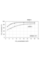
- 1 is a graph showing the relationship between CO 2 conversion and the CO 2 concentration in the feed gas in a methanation reaction test.
- 1 is a graph showing the relationship between CO 2 conversion and the CO 2 concentration in the feed gas in a methanation reaction test.
- 1 is a graph showing the relationship between CO 2 conversion and the CO 2 concentration in the feed gas in a methanation reaction test.
- 1 is a graph showing the relationship between CO 2 conversion and the set temperature of an electric furnace in a methanation reaction test.
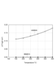
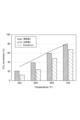
- 1 is a graph showing the relationship between pressure loss and the set temperature of an electric furnace in a methanation reaction test. 1 is a graph showing the relationship between CH 4 conversion and temperature in a dry reforming reaction test. 1 is a graph showing the relationship between CO 2 conversion and temperature in a dry reforming reaction test. 1 is a graph showing the relationship between CO 2 conversion and temperature in a reverse shift reaction test.
- the present invention is not limited to the following examples.
- FIG. 1 is a schematic diagram showing an example of a reaction apparatus used for producing a compound.
- the reaction apparatus 10 shown in FIG. 1 includes a reaction tube 1, a structure catalyst 3 accommodated in the reaction tube 1, and a gas inlet 5A and a gas outlet 5B provided at both ends of the reaction tube 1, respectively.
- a raw material gas G 0 containing a starting material is introduced into the reaction tube 1 from the gas inlet 5A.
- a gas-solid reaction proceeds due to the action of the catalyst possessed by the structure catalyst 3.
- a product gas G 1 containing a target compound, which is a product of the gas-solid reaction is discharged from the gas outlet 5B.
- the reaction tube 1 is heated by supplying heat from a heat source 7 provided outside the reaction tube 1.
- the heat source 7 is usually provided around the reaction tube 1.
- the heat source 7 is not particularly limited, and may be, for example, an electric heater that generates heat by resistance heating or the like, or a heat medium heated to a predetermined temperature.
- the temperature of the heat source 7 can be adjusted, for example, in the range of 5°C to 1000°C, taking into consideration the type of gas-solid reaction, etc.
- the length of the reaction tube 1 may be, for example, 10 to 20,000 mm.
- the inner diameter of the reaction tube 1 may be, for example, 5 to 200 mm.
- Multiple reaction tubes 1 may be provided.
- the inner surface of the reaction tube 1 may be non-porous.
- the porosity of the portion forming the non-porous inner surface of the reaction tube 1 may be 10% or less.
- the gas-solid reaction may include, for example, a methanation reaction in which methane is produced from carbon dioxide and hydrogen by the following reaction:
- the feed gas contains carbon dioxide and hydrogen
- the product gas contains the target compound methane and water.
- the feed gas may further contain oxygen.
- gas-solid reaction applied to the method according to the present disclosure is not limited to the methanation reaction.
- gas-solid reactions include a dehydrogenation reaction, a hydrogenation reaction, a steam reforming reaction, a dry reforming reaction, a water gas shift reaction, a reverse shift reaction, an ammonia synthesis reaction, an ammonia decomposition reaction, and a denitration reaction.
- FIG. 2 is a schematic diagram showing an example of a structure catalyst
- FIG. 3 is an end view of line III-III in FIG. 2.
- the structure catalyst 3 shown in FIG. 2 and FIG. 3 has a substrate 30 having a portion extending along a certain axis X, and a catalyst layer 35 covering the outer surface S of the substrate 30.
- the axis X is also the center line of the substrate 30.
- the catalyst layer 35 covers the entire outer surface of the substrate 30, but the catalyst layer 35 does not have to cover the entire outer surface of the substrate 30.
- the substrate 30 is composed of a plate-shaped portion that extends along the axis X while twisting in a direction rotating around the axis X as a whole.
- the structure catalyst 3 is inserted into the reaction tube 1 in a direction in which the axis X is parallel to the longitudinal direction of the reaction tube 1.
- Two or more structure catalysts 3 may be inserted in series into one reaction tube.
- the structure catalyst 3 inserted into the reaction tube 1 is not integrated with the reaction tube, so it can be easily removed from the reaction tube 1.
- the structure catalyst 3 is advantageous compared to a catalyst provided on a plate-shaped member that is provided protruding from the inner surface of the reaction tube.
- the structure catalyst 3 may be provided away from the inner surface of the reaction tube 1.
- the substrate 30 or a plate-like portion thereof has a porous metal portion including the outer surface of the substrate 30.
- the entire substrate 30 may be a porous metal portion, or the substrate 30 may have a porous metal portion located at the outermost layer and a non-porous internal structure provided inside the porous metal portion.
- the catalyst layer 35 is attached to the porous metal portion. A portion of the catalyst layer 35 may penetrate into the pores of the porous metal portion. In other words, the catalyst layer 35 may have a portion that penetrates into the pores of the porous metal portion and a portion that is provided outside the porous metal portion.
- the mass of the catalyst layer 35 attached to the substrate 30 may be 1 g or more and 1000 g or less per 1 L of substrate volume.
- the mass of the catalyst layer 35 attached to the substrate 30 may be 10 g or more, 20 g or more, 30 g or more, 40 g or more, or 50 g or more per 1 L of substrate volume.
- the substrate 30 having a porous metal portion makes it possible to easily increase the amount of the catalyst layer 35 attached.
- the volume of the substrate here includes the volume of the pores in the porous metal portion.
- the volume of the substrate refers to the volume of the cylindrical space formed by the substrate processed into a spiral shape. For example, the volume of a spiral substrate with a width of 100 mm and a length of 100 mm is 0.785 L.
- the porous metal portion may include pores that communicate with each other.
- the average pore size of the porous metal portion may be, for example, 1 ⁇ m or more and 100 mm or less.
- the average pore size here is the average value of the pore sizes of the multiple pores that make up the porous metal portion.
- the maximum width of the pores can be considered as the pore size of the pores.
- the average pore size can be, for example, the average value of the pore sizes of any 10 or more pores.
- the average pore size of the porous metal portion may be 5 ⁇ m or more, 10 ⁇ m or more, 50 ⁇ m or more, 0.1 mm or more, 0.2 mm or more, 0.3 mm or more, or 0.4 mm or more, or may be 50 mm or less, 40 mm or less, 30 mm or less, 20 mm or less, 10 mm or less, 5 mm or less, 4 mm or less, 3 mm or less, 2 mm or less, or 1 mm or less.
- the porosity of the porous metal part may be, for example, 40% or more and 99% or less.
- the porosity is the ratio of the volume of pores based on the total volume of the porous metal part including the volume of the pores.
- the porosity of the porous metal part may be 45% or more, 50% or more, 55% or more, 60% or more, 65% or more, 70% or more, 75% or more, 80% or more, or 90% or more, or may be 95% or less, 90% or less, 85% or less, 80% or less, 75% or less, 70% or less, 65% or less, or 60% or less.
- the porous metal portion of the substrate 30 can be a metal molding containing any metal.
- the porous metal portion may be a metal molding containing nickel, chromium, tin, aluminum, iron, tungsten, iron, cobalt, copper, zirconium, titanium, silicon, magnesium, stainless steel, or an alloy, oxide, or carbide containing these.
- a porous metal portion containing nickel or a nickel alloy can contribute to further improving the efficiency of gas-solid reactions.
- the length L of the substrate 30 (plate-shaped portion) in the direction along the axis X, the maximum width W in the direction perpendicular to the axis X, and the thickness T of the plate-shaped portion are set appropriately depending on the shape, size, etc. of the reaction tube.
- the length L may be, for example, 5 mm or more or 40 mm or more, and may be 2000 mm or less or 5000 mm or less.
- the length L is often greater than the maximum width W, but may be smaller than the maximum width W.
- the thickness of the substrate 30 (plate-shaped portion) or the structural catalyst 3 may be, for example, 0.1 mm or more and 100 mm or less.
- the maximum width W of the substrate 30 (plate-shaped portion) is set so that the structural catalyst 3 can be inserted into the reaction tube 1. If the maximum width W is close to the inner diameter of the reaction tube, it is advantageous in terms of making the device compact, and the efficiency of heat transfer from the reaction tube can be improved. Specifically, the ratio of the maximum width W of the substrate 30 to the inner diameter of the reaction tube 1 may be 0.85 or more or 0.90 or more, or 1.0 or less or 0.95 or less. The maximum width W may be, for example, 2 mm or more or 5 mm or more, or 500 mm or less or 100 mm or less.
- the axis X which is the center of torsion, is located inside the substrate 30.
- the substrate 30 may have a structure in which the axis X is located outside the substrate 30 and pores are formed on and near the axis X.
- a structure in which the axis X is located inside the substrate 30 may be advantageous.
- the plate-shaped portion of the substrate is twisted in one direction around the axis X, but the shape of the substrate (plate-shaped portion) is not limited to this and can be modified as appropriate.
- the substrate (plate-shaped portion) may include a portion twisted in a clockwise direction and a portion twisted in a counterclockwise direction when viewed from the direction along the axis X.
- the period of twisting does not need to be constant and may vary.
- the substrate (plate-shaped portion) may be a static mixer element.
- a substrate including a twisted plate-shaped body can be obtained by processing a molded body by a conventional method.
- the catalyst layer 35 contains a catalyst that promotes the gas-solid reaction.
- the type of catalyst can be selected depending on the type of gas-solid reaction, etc.
- the catalyst may contain one or more catalytic metals selected from the group consisting of nickel, ruthenium, rhodium, potassium, calcium, sodium, and iridium. These catalytic metals function as catalysts that promote, for example, a methanation reaction.
- the catalyst constituting the catalyst layer 35 may contain one or more catalytic metals selected from the group consisting of nickel, magnesium, zirconium, silicon, titanium, aluminum, ruthenium, and rhodium, and one or more metal oxides selected from the group consisting of nickel oxide (NiO 2 ), aluminum oxide (Al 2 O 3 ), zirconium oxide (ZrO 2 ), silicon oxide (SiO 2 ), magnesium oxide (MgO), and titanium oxide (TiO 2 ).
- a catalyst containing these components functions as a catalyst for promoting a dry reforming reaction, for example.
- the catalyst constituting the catalyst layer 35 may contain one or more catalytic metals selected from the group consisting of copper, nickel, zinc, aluminum, ruthenium, platinum, rhodium, silver, chromium, and magnesium, and one or more metal oxides selected from zinc oxide (ZnO), aluminum oxide (Al 2 O 3 ), chromium oxide (Cr 2 O 3 ), silicon oxide (SiO 2 ), and magnesium oxide (MgO). Catalysts containing these components function, for example, as catalysts to promote the water gas shift reaction and the reverse water gas shift reaction.
- the catalyst constituting the catalyst layer 35 may include a carrier that supports a catalytic metal.
- the carrier contains, for example, a metal oxide containing at least one metal element selected from cerium, zirconium, yttrium, aluminum, silicon, and magnesium.
- the metal oxide may contain two or more metal elements selected from cerium, zirconium, yttrium, aluminum, silicon, and magnesium.
- the support may be cerium oxide ( CeO2 ) , zirconium oxide (ZrO2), yttrium oxide ( Y2O3 ), aluminum oxide ( Al2O3 ), silicon oxide ( SiO2 ) , magnesium oxide (MgO), zinc oxide (ZnO), chromium oxide ( Cr2O3 , Cr3O4 ) , iron oxide ( Fe2O3 , Fe3O4 ), or a composite oxide containing cerium, zirconium, yttrium, aluminum, silicon, and at least one metal element selected from magnesium, zinc , chromium, and iron .
- the composite oxide may contain two or more metal elements selected from cerium, zirconium, yttrium, aluminum, silicon, and magnesium.
- the amount of catalyst metal contained in the catalyst layer 35 is not particularly limited, but may be, for example, 0.01 to 50 mass% based on the mass of the carrier.
- the total content of the carrier and catalyst metal in the catalyst layer 35 may be, for example, 0.1 to 100 mass%, 1 to 100 mass%, 10 to 100 mass%, 30 to 100 mass%, 50 to 100 mass%, 70 to 100 mass%, 80 to 100 mass%, or 90 to 100 mass% based on the mass of the catalyst layer 35.
- the spiral-type structure catalyst can be manufactured, for example, by a method including preparing a catalyst dispersion liquid containing a particulate catalyst and a dispersing medium, immersing a spiral-type substrate having a porous metal portion in the catalyst dispersion liquid, removing the substrate from the catalyst dispersion liquid, and removing the dispersing medium from the catalyst dispersion liquid adhering to the substrate.
- a portion of the catalyst layer often penetrates into the pores of the porous metal portion.
- the dispersing medium contained in the catalyst dispersion liquid may be water, alcohol, or a combination of these.
- the present invention is not limited to the following examples.
- Test 1A Methanation reaction 1-1.
- Structural catalyst (1) Spiral-type substrate The following porous metal substrate, which is a plate-shaped formed body of a nickel-chromium alloy, and a non-porous aluminum substrate were prepared as substrates. Porous metal substrate: Effective area (specific surface area): 1200-6000 m 2 /m 3 , width: 11 mm, length: 150 mm, thickness: 1.2 mm, average pore size: 0.5-1.0 mm, porosity: 60-98% Aluminum substrate: Width: 11 mm, Length: 150 mm, Thickness: 1.0 mm
- FIG. 4 is a photograph of an example of the structural catalyst produced.
- a catalyst slurry in which Ru-loaded CeO2 particles (Ru/ CeO2 ) were dispersed in water was prepared, and a structural catalyst having a catalyst layer containing Ru/ CeO2 and covering the outer surface of a substrate was obtained in the same manner as above.
- the amount of the catalyst layer attached per metal member was 1.1 g for the porous Ni-Cr member and 0.33 g for the aluminum member.
- the amount of the catalyst layer attached per 1 L of substrate volume was 78 g/L for the porous Ni-Cr member and 23 g/L for the aluminum member.
- Methanation reaction test Example 1A Three structural catalysts having a porous Ni-Cr member and a catalyst layer containing Ni/CeO 2 were inserted in series into a first reaction tube (inner diameter: 12 mm) having a gas inlet and a gas outlet. Three structural catalysts having a porous Ni-Cr member and a catalyst layer containing Ru/CeO 2 were inserted in series into a second reaction tube (inner diameter: 12 mm) connected to the first reaction tube via a pipe on the gas outlet side. A raw material gas containing carbon dioxide and hydrogen, and oxygen gas were continuously introduced from the gas inlet of the first reaction tube. The gas flowing out from the first reaction tube was introduced into the second reaction tube together with additional oxygen gas.
- the CO 2 concentration in the product gas flowing out from the second reaction tube was quantified, and the conversion rate of CO 2 to methane (CO 2 conversion) was obtained from the measurement results.
- This methanation reaction test was carried out while changing the carbon dioxide concentration in the raw material gas under the condition that the first and second reaction tubes were heated in an electric furnace at 200° C. or 100° C., and under the condition that the reaction tubes were not heated in an electric furnace.
- Other reaction conditions were as follows. Gas flow rate: 3.0 L/min H2 /CO2 ratio : 4.0 (stoichiometric) CO2 concentration: 1 to 16% by volume O2 concentration: 3% by volume (first and second reaction tubes)
- Comparative Example 1A The same reaction test as in Example 1 was carried out except that three structural catalysts having an aluminum member and a catalyst layer containing Ni/ CeO2 were inserted into the first reaction tube, and three structural catalysts having an aluminum member and a catalyst layer containing Ru/ CeO2 were inserted into the second reaction tube.
- FIGs 5, 6 and 7 are graphs showing the relationship between CO 2 conversion and CO 2 concentration in the raw material gas.
- Figure 5 shows the results under reaction conditions with a heating temperature of 200°C
- Figure 6 shows the results under reaction conditions with a heating temperature of 100°C
- Figure 7 shows the results under reaction conditions without heating the reaction tube.
- the structural catalyst having a spiral-type porous Ni-Cr member (Example 1A) showed significantly higher CO 2 conversion than the structural catalyst having a spiral-type non-porous aluminum member (Comparative Example 1A).
- the difference between the two was large under reaction conditions without heating by an electric furnace.
- the effect confirmed here exceeds the extent expected from the increase in catalyst amount alone, and can be said to be exerted by a specific action due to the combination of the porous metal member and the spiral-type shape.
- Test 1B Methanation reaction 1-1.
- Structural catalyst (1) Spiral-type substrate The following porous metal substrate, which is a plate-shaped formed body of a nickel-chromium alloy, and a non-porous aluminum substrate were prepared as substrates. Porous metal substrate: Effective area (specific surface area): 1000-7000 m 2 /m 3 , width: 7 mm, length: 50 mm, average pore size: 0.4-1.0 mm Aluminum substrate: Width: 7mm, Length: 50mm
- Both ends of each substrate were gripped and the substrate was twisted in a direction rotating about an axis along the longitudinal direction of the substrate, thereby obtaining a porous Ni-Cr member and a non-porous aluminum member as spiral-type substrates having a porous metal portion.
- (2) Formation of catalytic layer A porous Ni-Cr member or a non-porous aluminum member was used as the substrate, and a catalytic layer containing Ru/ CeO2 and covering the outer surface of the substrate was formed in the same manner as in Test 1A to obtain a structural catalyst.
- the Ru content in Ru/ CeO2 was 10 mass% based on the mass of Ru/ CeO2 .
- the amount of the catalytic layer attached per substrate was 0.15 g.
- Granular catalyst The following catalyst, which is CeO2 particles carrying Ru, was diluted with quartz sand to prepare a granular catalyst.
- Methanation reaction test Example 1B Four structural catalysts having a porous Ni-Cr member and a catalyst layer containing Ni/CeO 2 were inserted in series into a reaction tube (inner diameter: 8 mm) having a gas inlet and a gas outlet. The total length of the four structural catalysts was 200 mm. A raw material gas containing carbon dioxide, hydrogen, nitrogen and oxygen was continuously introduced from the gas inlet of the reaction tube. The CO 2 concentration in the product gas flowing out from the reaction tube was quantified, and the conversion rate (CO 2 conversion) from CO 2 to methane was obtained from the measurement results.
- Comparative Example 1B A reaction test was carried out in the same manner as in Example 1B, except that four structural catalysts having an aluminum member and a catalyst layer containing Ni/ CeO2 were inserted into the reaction tube.
- Comparative Example 2B A granular catalyst containing Ni/ CeO2 was placed in a reaction tube of the same size as in Example 1B to form a catalyst layer of 200 mm in length. The amount of Ni/ CeO2 contained in the catalyst layer was 0.6 g. A methanation reaction test using this catalyst layer was carried out under the same conditions as in Example 1B. The pressure on the upstream side of the catalyst layer and the pressure on the downstream side of the catalyst layer were measured, and the difference between them was taken as the pressure loss ⁇ P.
- Results Figure 8 is a graph showing the relationship between CO 2 conversion and the set temperature of the electric furnace. Equilibrium in the figure indicates the CO 2 conversion rate at equilibrium at each temperature.
- the structural catalyst having a spiral-type porous Ni-Cr member (Example 1B) showed significantly higher CO 2 conversion than the structural catalyst having a spiral-type non-porous aluminum member (Comparative Example 1B). In particular, the difference between the two was large under low-temperature reaction conditions of 150 to 250°C.
- Figure 9 is a graph showing the relationship between pressure loss ⁇ P and the installation temperature of the electric furnace.
- the catalyst layer of Comparative Example 2B which contains a granular catalyst
- Example 1B which used a spiral-type structure catalyst, virtually no pressure loss was observed regardless of temperature.
- Test 2 Dry Reforming Reaction 2-1. Structural Catalyst (1) Spiral-Type Substrate The following porous metal substrate, which is a plate-shaped formed body of a nickel-chromium alloy, and a non-porous stainless steel substrate were prepared as substrates. Porous metal substrate: Effective area (specific surface area): 1200-1500 m 2 /m 3 , width: 7 mm, length: 55 mm, thickness: 2.2 mm, average pore size: 0.85 mm Stainless steel substrate: Width: 7 mm, Length: 55 mm, Thickness: 0.1 mm
- Each substrate was immersed in an aqueous sodium hydroxide solution.
- Each substrate removed from the aqueous sodium hydroxide solution was immersed in a catalyst slurry (catalyst dispersion liquid) in which Ni-loaded Al 2 O 3 particles (Ni/Al 2 O 3 ) were dispersed in water at room temperature for about 0.56 to 5 minutes.
- the catalyst slurry attached to the substrate removed from the catalyst slurry was dried with hot air to obtain a structural catalyst having a catalyst layer containing Ni/Al 2 O 3 and covering the outer surface of the substrate.
- the amount of the catalytic layer attached per substrate was 93.9 mg for the porous Ni-Cr member and 20.6 mg for the stainless steel member.
- the amount of the catalytic layer attached per 1 L of substrate volume was 45 g/L for the porous Ni-Cr member and 10 g/L for the stainless steel member.
- Dry reforming reaction test example 2 Six structural catalysts each having a porous Ni-Cr member and a catalyst layer containing Ni/Al 2 O 3 were inserted in series into a reaction tube (inner diameter: 8 mm) having a gas inlet and a gas outlet. A raw material gas containing methane and carbon dioxide was continuously introduced from the gas inlet of the reaction tube. The concentrations of methane and carbon dioxide in the product gas flowing out from the reaction tube were quantified, and the conversion rates of methane and carbon dioxide were calculated from the measurement results.
- This dry reforming reaction test was carried out under the condition that the reaction tube was heated to 550, 600°C, 650°C, or 700°C in an electric furnace. Other reaction conditions were as follows. Gas flow rate: 1000 mL/min CO2 /CH4 ratio : 1.2
- Comparative Example 2 A reaction test was carried out in the same manner as in Example 2, except that six structural catalysts having a stainless steel member and a catalyst layer containing Ni/Al 2 O 3 were inserted into the reaction tube.
- FIG. 10 is a graph showing the relationship between the methane conversion rate (CH 4 conversion) and the temperature (set temperature of the electric furnace).
- FIG. 11 is a graph showing the relationship between the carbon dioxide conversion rate (CO 2 conversion) and the temperature (set temperature of the electric furnace). Equilibrium in each figure indicates the conversion rate of CH 4 or CO 2 in equilibrium at each temperature.
- the structural catalyst having a spiral-type porous Ni—Cr member Example 2 showed significantly higher CH 4 conversion and CO 2 conversion than the structural catalyst having a spiral-type non-porous stainless steel member (Comparative Example 2).
- Test 3 Reverse Shift Reaction 3-1.
- Structural Catalyst The following porous metal substrate, which is a plate-shaped formed body of a nickel-chromium alloy, and a non-porous stainless steel substrate were prepared as substrates.
- Porous metal substrate Effective area (specific surface area): 3,000 to 6,000 m 2 /m 3 , width: 7 mm, length: 100 mm, thickness: 1.2 mm, average pore size: 0.51 mm, porosity: 60 to 98%
- Each substrate was immersed in an aqueous sodium hydroxide solution.
- Each substrate removed from the aqueous sodium hydroxide solution was immersed in a catalyst slurry (catalyst dispersion liquid) in which CeO 2 particles carrying Ru (Ru/CeO 2 , Ru: 10% by mass) were dispersed in water at room temperature for about 0.5 to 5.0 minutes.
- the catalyst slurry attached to the substrate removed from the catalyst slurry was dried with hot air to obtain a structural catalyst having a catalyst layer containing Ru/CeO 2 and covering the outer surface of the substrate.
- the amount of the catalytic layer attached per substrate was 1.2 g for the porous Ni-Cr member and 0.4 g for the aluminum member.
- the amount of the catalytic layer attached per 1 L of substrate volume was 160 g/L for the porous Ni-Cr member and 80 g/L for the aluminum member.
- Comparative Example 3 A reaction test was carried out in the same manner as in Example 3, except that two structural catalysts having an aluminum member and a catalyst layer containing Ru/ CeO2 were inserted into the reaction tube.
- Results Figure 12 is a graph showing the relationship between the carbon dioxide conversion rate (CO 2 conversion) and temperature (set temperature of the electric furnace). Equilibrium in the figure indicates the CO 2 conversion rate at equilibrium at each temperature.
- the structural catalyst having a spiral-type porous Ni-Cr member (Example 3) showed significantly higher CO 2 conversion than the structural catalyst having a spiral-type non-porous aluminum member (Comparative Example 3).
Landscapes
- Chemical & Material Sciences (AREA)
- Organic Chemistry (AREA)
- Chemical Kinetics & Catalysis (AREA)
- Engineering & Computer Science (AREA)
- Materials Engineering (AREA)
- Inorganic Chemistry (AREA)
- General Health & Medical Sciences (AREA)
- Combustion & Propulsion (AREA)
- Health & Medical Sciences (AREA)
- Oil, Petroleum & Natural Gas (AREA)
- Analytical Chemistry (AREA)
- General Chemical & Material Sciences (AREA)
- Catalysts (AREA)
Abstract
Description
[1]
一定の軸線に沿って延在する基材と、
前記基材上に設けられた触媒層と、
を含み、
前記基材が、前記基材の外表面を含む多孔質金属部を有し、前記触媒層が前記多孔質金属部に付着しており、
前記基材が、前記軸線を中心として回転する方向にねじれながら前記軸線に沿って延在している板状部を有する、
構造体触媒。
[2]
前記触媒層の質量が、前記基材の体積1L当たり1.0g以上である、[1]に記載の構造体触媒。
[3]
前記多孔質金属部の平均孔径が0.1mm以上である、[1]又は[2]に記載の構造体触媒。
[4]
前記触媒層が、前記基材の外表面全体を覆っている、[1]~[3]のいずれかに記載の構造体触媒。
[5]
[1]~[4]のいずれかに記載の構造体触媒が設けられた反応管内での気固系反応によって、原料ガスから目的の化合物を生成させることを含み、
前記構造体触媒が、前記軸線が前記反応管の長手方向に平行になる向きで前記反応管に挿入されている、
化合物を製造する方法。
[6]
反応管と、
該反応管内に収容された[1]~[4]のいずれかに記載の構造体触媒と、
を具備し、
前記構造体触媒が、前記軸線が前記反応管の長手方向に平行になる向きで前記反応管に挿入されている、
反応装置。
CO2+4H2→CH4+2H2O
1-1.構造体触媒
(1)スパイラル型の基材
ニッケルクロム合金の板状の成形体である以下の多孔質金属基板、及び非多孔質のアルミニウム基板を基材として準備した。
多孔質金属基板:
有効面積(比表面積):1200~6000m2/m3、幅:11mm、長さ:150mm、厚さ:1.2mm、平均孔径:0.5~1.0mm、空孔率:60~98%
アルミニウム基板:
幅:11mm、長さ:150mm、厚さ:1.0mm
各基材を水酸化ナトリウム水溶液に浸漬した。水酸化ナトリウム水溶液から取り出した各基材を、Niを担持したCeO2粒子(Ni/CeO2)が水に分散した触媒スラリー(触媒分散液)に、室温で約0.5~10分間、浸漬した。触媒スラリーから取り出した基材に付着した触媒スラリーを熱風で乾燥して、Ni/CeO2を含み基材の外表面を覆う触媒層を有する構造体触媒を得た。触媒層の基材1個当たりの付着量は、多孔質Ni-Cr部材において1.1gで、アルミニウム部材において0.33gであった。触媒層の基材の体積1L当たりの付着量は、多孔質Ni-Cr部材において78g/Lで、アルミニウム部材において23g/Lであった。図4は、作製された構造体触媒の一例の写真である。
実施例1A
ガス入口及びガス出口を有する第一反応管(内径:12mm)に、多孔質Ni-Cr部材、及びNi/CeO2を含む触媒層を有する3本の構造体触媒を直列に挿入した。第一反応管にガス出口側で配管を介して接続された第二反応管(内径:12mm)に、多孔質Ni-Cr部材、及びRu/CeO2を含む触媒層を有する3本の構造体触媒を直列に挿入した。第一反応管のガス入口から、二酸化炭素及び水素を含む原料ガス、及び酸素ガスを連続的に導入した。第一反応管から流出したガスを、追加の酸素ガスとともに第二反応管に導入した。第二反応管から流出した生成物ガスにおけるCO2濃度を定量し、測定結果から、CO2からメタンへの転化率(CO2 conversion)を求めた。このメタネーション反応試験を、第一反応管及び第二反応管を電気炉で200℃又は100℃で加熱する条件、及び反応管を電気炉で加熱しない条件で、原料ガスにおける二酸化炭素の濃度を変化させながら行った。その他の反応条件は以下のとおりであった。
ガス流量:3.0L/分
H2/CO2比:4.0(化学量論)
CO2濃度:1~16体積%
O2濃度:3体積%(第一反応管及び第二反応管)
アルミニウム部材、及びNi/CeO2を含む触媒層を有する3本の構造体触媒を第一反応管に挿入し、アルミニウム部材、及びRu/CeO2を含む触媒層を有する3本の構造体触媒を第二反応管に挿入したこと以外は実施例1と同様の反応試験を行った。
図5、図6及び図7は、CO2 conversionと、原料ガスにおけるCO2濃度との関係を示すグラフである。図5は加熱温度が200℃である反応条件の結果を示し、図6は加熱温度が100℃である反応条件の結果を示し、図7は反応管を加熱しない反応条件の結果を示す。スパイラル型の多孔質Ni-Cr部材を有する構造体触媒(実施例1A)は、スパイラル型の非多孔質のアルミニウム部材を有する構造体触媒(比較例1A)と比較して、有意に高いCO2 conversionを示した。特に、電気炉による加熱のない反応条件のときに両者の差が大きかった。ここで確認された効果は、触媒量の増加だけから想定される程度を超えるものであり、多孔質金属部材とスパイラル型の形状との組合せによる特異的な作用によって発揮されたといえる。
1-1.構造体触媒
(1)スパイラル型の基材
ニッケルクロム合金の板状の成形体である以下の多孔質金属基板、及び非多孔質のアルミニウム基板を基材として準備した。
多孔質金属基板:
有効面積(比表面積):1000~7000m2/m3、幅:7mm、長さ:50mm、平均孔径:0.4~1.0mm
アルミニウム基板:
幅:7mm、長さ:50mm
(2)触媒層の形成
基材として多孔質Ni-Cr部材、又は非多孔質アルミニウム部材を用い、Ru/CeO2を含み基材の外表面を覆う触媒層を、試験1Aと同様の方法で形成して、構造体触媒を得た。Ru/CeO2におけるRuの含有量は、Ru/CeO2の質量を基準として10質量%であった。多孔質Ni-Cr部材、及び非多孔質アルミニウム部材のいずれの場合も、触媒層の基材1個当たりの付着量は0.15gであった。
Ruを担持したCeO2粒子である以下の触媒を石英砂にて希釈した粒状触媒を準備した。
触媒:Ru/CeO2(Ru含有量:Ru/CeO2の質量を基準として10質量%)
平均粒径:0.5mm
触媒量:0.6g
実施例1B
ガス入口及びガス出口を有する反応管(内径:8mm)に、多孔質Ni-Cr部材、及びNi/CeO2を含む触媒層を有する4本の構造体触媒を直列に挿入した。4本の構造体触媒の合計の長さは200mmであった。反応管のガス入口から、二酸化炭素、水素、窒素及び酸素を含む原料ガスを連続的に導入した。反応管から流出した生成物ガスにおけるCO2濃度を定量し、測定結果から、CO2からメタンへの転化率(CO2 conversion)を求めた。このメタネーション反応試験を、反応管を150℃、200℃、250℃、300℃、350℃又は400℃に設定された電気炉内で加熱する条件で行った。各ガスの流量は以下のとおりであった。構造体触媒の上流側の圧力、及び構造体触媒の下流側における圧力を測定し、それらの差を圧力損失ΔPとした。
総ガス流量:1000mL/分
CO2流量:100mL/分(10体積%)
H2流量:460mL/分(46体積%)
N2流量:410mL/分(41体積%)
O2流量:30mL/分(3体積%)
アルミニウム部材、及びNi/CeO2を含む触媒層を有する4本の構造体触媒を反応管に挿入したこと以外は実施例1Bと同様の反応試験を行った。
実施例1Bと同じサイズの反応管に、Ni/CeO2を含む粒状触媒を入れ、長さ200mmの触媒層を形成した。触媒層に含まれるNi/CeO2の量は0.6gであった。この触媒層によるメタネーション反応試験を、実施例1Bと同様の条件で行った。触媒層の上流側の圧力、及び触媒層の下流側における圧力を測定し、それらの差を圧力損失ΔPとした。
図8は、CO2 conversionと、電気炉の設定温度との関係を示すグラフである。図中のEquilibriumは、各温度における平衡状態でのCO2の転化率を示す。スパイラル型の多孔質Ni-Cr部材を有する構造体触媒(実施例1B)は、スパイラル型の非多孔質のアルミニウム部材を有する構造体触媒(比較例1B)と比較して、有意に高いCO2 conversionを示した。特に、150~250℃の低温の反応条件のときに両者の差が大きかった。
2-1.構造体触媒
(1)スパイラル型の基材
ニッケルクロム合金の板状の成形体である以下の多孔質金属基板、及び非多孔質のステンレス基板を基材として準備した。
多孔質金属基板:
有効面積(比表面積):1200~1500m2/m3、幅:7mm、長さ:55mm、厚さ:2.2mm、平均孔径:0.85mm
ステンレス基板:
幅:7mm、長さ:55mm、厚さ:0.1mm
各基材を水酸化ナトリウム水溶液に浸漬した。水酸化ナトリウム水溶液から取り出した各基材を、Niを担持したAl2O3粒子(Ni/Al2O3)が水に分散した触媒スラリー(触媒分散液)に、室温で約0.56~5分間、浸漬した。触媒スラリーから取り出した基材に付着した触媒スラリーを熱風で乾燥して、Ni/Al2O3を含み基材の外表面を覆う触媒層を有する構造体触媒を得た。触媒層の基材1個当たりの付着量は、多孔質Ni-Cr部材において93.9mgで、ステンレス部材において20.6mgであった。触媒層の基材の体積1L当たりの付着量は、多孔質Ni-Cr部材において45g/Lで、ステンレス部材において10g/Lであった。
実施例2
ガス入口及びガス出口を有する反応管(内径:8mm)に、多孔質Ni-Cr部材、及びNi/Al2O3を含む触媒層を有する6本の構造体触媒を直列に挿入した。反応管のガス入口から、メタン及び二酸化炭素を含む原料ガスを連続的に導入した。反応管から流出した生成物ガスにおけるメタン及び二酸化炭素の濃度を定量し、測定結果から、メタン及び二酸化炭素の転化率を求めた。このドライ改質反応試験を、反応管を電気炉で550、600℃、650℃、又は700℃に加熱する条件で行った。その他の反応条件は以下のとおりであった。
ガス流量:1000mL/分
CO2/CH4比:1.2
ステンレス部材、及びNi/Al2O3を含む触媒層を有する6本の構造体触媒を反応管に挿入したこと以外は実施例2と同様の反応試験を行った。
図10は、メタンの転化率(CH4 conversion)と、温度(電気炉の設定温度)との関係を示すグラフである。図11は、二酸化炭素の転化率(CO2 conversion)と、温度(電気炉の設定温度)との関係を示すグラフである。各図中のEquilibriumは、各温度における平衡状態でのCH4又はCO2の転化率を示す。スパイラル型の多孔質Ni-Cr部材を有する構造体触媒(実施例2)は、スパイラル型の非多孔質のステンレス部材を有する構造体触媒(比較例2)と比較して、有意に高いCH4 conversion及びCO2 conversionを示した。
3-1.構造体触媒
(1)スパイラル型の基材
ニッケルクロム合金の板状の成形体である以下の多孔質金属基板、及び非多孔質のステンレス基板を基材として準備した。
多孔質金属基板:
有効面積(比表面積):3,000~6,000m2/m3、幅:7mm、長さ:100mm、厚さ:1.2mm、平均孔径:0.51mm、空孔率:60~98%
アルミニウム基板:
幅:7mm、長さ:100mm、厚さ:1.0mm
各基材を水酸化ナトリウム水溶液に浸漬した。水酸化ナトリウム水溶液から取り出した各基材を、Ruを担持したCeO2粒子(Ru/CeO2、Ru:10質量%)が水に分散した触媒スラリー(触媒分散液)に、室温で約0.5~5.0分間、浸漬した。触媒スラリーから取り出した基材に付着した触媒スラリーを熱風で乾燥して、Ru/CeO2を含み基材の外表面を覆う触媒層を有する構造体触媒を得た。触媒層の基材1個当たりの付着量は、多孔質Ni-Cr部材において1.2gで、アルミニウム部材において0.4gであった。触媒層の基材の体積1L当たりの付着量は、多孔質Ni-Cr部材において160g/Lで、アルミニウム部材において80g/Lであった。
実施例3
ガス入口及びガス出口を有する反応管(内径:8mm)に、多孔質Ni-Cr部材、及びRu/CeO2を含む触媒層を有する2本の構造体触媒を直列に挿入した。反応管のガス入口から、二酸化炭素、水素及び窒素を含む原料ガスを連続的に導入した。反応管から流出した生成物ガスにおける二酸化炭素の濃度を定量し、測定結果から、二酸化炭素の転化率を求めた。このドライ改質反応試験を、反応管を電気炉で400、450℃、500℃、550℃、又は600℃に加熱する条件で行った。その他の反応条件は以下のとおりであった。
ガス流量:500mL/分
CO2/H2/N2比:1/1/0.5
アルミニウム部材、及びRu/CeO2を含む触媒層を有する2本の構造体触媒を反応管に挿入したこと以外は実施例3と同様の反応試験を行った。
図12は、二酸化炭素の転化率(CO2 conversion)と、温度(電気炉の設定温度)との関係を示すグラフである。図中のEquilibriumは、各温度における平衡状態でのCO2の転化率を示す。スパイラル型の多孔質Ni-Cr部材を有する構造体触媒(実施例3)は、スパイラル型の非多孔質のアルミニウム部材を有する構造体触媒(比較例3)と比較して、有意に高いCO2 conversionを示した。
Claims (6)
- 一定の軸線に沿って延在する基材と、
前記基材上に設けられた触媒層と、
を含み、
前記基材が、前記基材の外表面を含む多孔質金属部を有し、前記触媒層が前記多孔質金属部に付着しており、
前記基材が、前記軸線を中心として回転する方向にねじれながら前記軸線に沿って延在している板状部を有する、
構造体触媒。 - 前記触媒層の質量が、前記基材の体積1L当たり1g以上である、請求項1に記載の構造体触媒。
- 前記多孔質金属部の平均孔径が0.1mm以上である、請求項1に記載の構造体触媒。
- 前記触媒層が、前記基材の外表面全体を覆っている、請求項1に記載の構造体触媒。
- 請求項1~4のいずれか一項に記載の構造体触媒が設けられた反応管内での気固系反応によって、原料ガスから目的の化合物を生成させることを含み、
前記構造体触媒が、前記軸線が前記反応管の長手方向に平行になる向きで前記反応管に挿入されている、
化合物を製造する方法。 - 反応管と、
該反応管内に収容された請求項1~4のいずれか一項に記載の構造体触媒と、
を具備し、
前記構造体触媒が、前記軸線が前記反応管の長手方向に平行になる向きで前記反応管に挿入されている、
反応装置。
Priority Applications (3)
| Application Number | Priority Date | Filing Date | Title |
|---|---|---|---|
| EP24813104.7A EP4714543A1 (en) | 2023-06-02 | 2024-05-31 | Structure catalyst, method for producing compound, and reaction device |
| CN202480036178.3A CN121219072A (zh) | 2023-06-02 | 2024-05-31 | 结构体催化剂、制造化合物的方法和反应装置 |
| JP2025524921A JPWO2024248149A1 (ja) | 2023-06-02 | 2024-05-31 |
Applications Claiming Priority (2)
| Application Number | Priority Date | Filing Date | Title |
|---|---|---|---|
| JP2023-091756 | 2023-06-02 | ||
| JP2023091756 | 2023-06-02 |
Publications (1)
| Publication Number | Publication Date |
|---|---|
| WO2024248149A1 true WO2024248149A1 (ja) | 2024-12-05 |
Family
ID=93657645
Family Applications (1)
| Application Number | Title | Priority Date | Filing Date |
|---|---|---|---|
| PCT/JP2024/020102 Ceased WO2024248149A1 (ja) | 2023-06-02 | 2024-05-31 | 構造体触媒、化合物を製造する方法、及び反応装置 |
Country Status (4)
| Country | Link |
|---|---|
| EP (1) | EP4714543A1 (ja) |
| JP (1) | JPWO2024248149A1 (ja) |
| CN (1) | CN121219072A (ja) |
| WO (1) | WO2024248149A1 (ja) |
Citations (7)
| Publication number | Priority date | Publication date | Assignee | Title |
|---|---|---|---|---|
| JPH06261841A (ja) * | 1993-03-16 | 1994-09-20 | Hitachi Home Tec Ltd | 汚物焼却器の脱臭装置 |
| JP2012236182A (ja) * | 2011-05-09 | 2012-12-06 | Nippon Seisen Co Ltd | 触媒用担体とこれを用いた触媒製品、触媒モジュール |
| WO2016039385A1 (ja) * | 2014-09-09 | 2016-03-17 | 国立大学法人静岡大学 | 有機ハイドライド用脱水素触媒及びその製造方法 |
| JP2016159266A (ja) * | 2015-03-04 | 2016-09-05 | 国立大学法人静岡大学 | 触媒構造体及びその製造方法、並びに水素発生装置。 |
| JP2020033280A (ja) | 2018-08-28 | 2020-03-05 | 国立大学法人静岡大学 | メタンを製造する方法、及び製造システム |
| WO2022210469A1 (ja) * | 2021-03-31 | 2022-10-06 | 三菱重工業株式会社 | 均温化された熱交換型触媒反応器 |
| WO2023286803A1 (ja) * | 2021-07-13 | 2023-01-19 | 三菱重工業株式会社 | 等温化した反応装置 |
-
2024
- 2024-05-31 JP JP2025524921A patent/JPWO2024248149A1/ja active Pending
- 2024-05-31 EP EP24813104.7A patent/EP4714543A1/en active Pending
- 2024-05-31 CN CN202480036178.3A patent/CN121219072A/zh active Pending
- 2024-05-31 WO PCT/JP2024/020102 patent/WO2024248149A1/ja not_active Ceased
Patent Citations (7)
| Publication number | Priority date | Publication date | Assignee | Title |
|---|---|---|---|---|
| JPH06261841A (ja) * | 1993-03-16 | 1994-09-20 | Hitachi Home Tec Ltd | 汚物焼却器の脱臭装置 |
| JP2012236182A (ja) * | 2011-05-09 | 2012-12-06 | Nippon Seisen Co Ltd | 触媒用担体とこれを用いた触媒製品、触媒モジュール |
| WO2016039385A1 (ja) * | 2014-09-09 | 2016-03-17 | 国立大学法人静岡大学 | 有機ハイドライド用脱水素触媒及びその製造方法 |
| JP2016159266A (ja) * | 2015-03-04 | 2016-09-05 | 国立大学法人静岡大学 | 触媒構造体及びその製造方法、並びに水素発生装置。 |
| JP2020033280A (ja) | 2018-08-28 | 2020-03-05 | 国立大学法人静岡大学 | メタンを製造する方法、及び製造システム |
| WO2022210469A1 (ja) * | 2021-03-31 | 2022-10-06 | 三菱重工業株式会社 | 均温化された熱交換型触媒反応器 |
| WO2023286803A1 (ja) * | 2021-07-13 | 2023-01-19 | 三菱重工業株式会社 | 等温化した反応装置 |
Also Published As
| Publication number | Publication date |
|---|---|
| CN121219072A (zh) | 2025-12-26 |
| EP4714543A1 (en) | 2026-03-25 |
| JPWO2024248149A1 (ja) | 2024-12-05 |
Similar Documents
| Publication | Publication Date | Title |
|---|---|---|
| JP3473898B2 (ja) | 水素精製装置 | |
| JP5015638B2 (ja) | 選択透過膜型反応器及び水素製造方法 | |
| JP4216067B2 (ja) | 水素に富んだガスを発生させる方法 | |
| EP0082614B1 (en) | Process for steam reforming a hydrocarbon feedstock and catalyst therefor | |
| US12459814B2 (en) | Steam reforming | |
| US20040048114A1 (en) | Simplified article for carbon monoxide removal | |
| CN102665896A (zh) | 逆转移反应用催化剂和使用其的合成气体的制造方法 | |
| WO2006082933A1 (ja) | 選択透過膜型反応器 | |
| US6923944B2 (en) | Membrane reactor for gas extraction | |
| JP2005529824A (ja) | 水−気体転化用白金族金属触媒のメタン化活性の抑制 | |
| GB2053957A (en) | Catalytic process involving carbon monoxide and hydrogen | |
| JP5161763B2 (ja) | 選択透過膜型反応器を用いた水素製造方法 | |
| JP2008239360A (ja) | 選択透過膜型反応器 | |
| JP4185952B2 (ja) | 一酸化炭素除去触媒及びその製造方法並びに一酸化炭素除去装置 | |
| JPWO2005070519A1 (ja) | 選択透過膜型反応器 | |
| WO2024248149A1 (ja) | 構造体触媒、化合物を製造する方法、及び反応装置 | |
| JP5139971B2 (ja) | 選択透過膜型反応器を用いた水素製造方法 | |
| JP5354516B2 (ja) | 水素分離体 | |
| JP4663095B2 (ja) | 水素精製装置 | |
| WO2025183110A1 (ja) | 気固触媒反応により化合物を製造する方法、及び反応装置 | |
| JPS6021772B2 (ja) | ニツケル金属触媒の製造方法 | |
| JP5086599B2 (ja) | 水素含有ガスの製造方法 | |
| WO2025204370A1 (ja) | メタン製造反応器 | |
| RU2621689C1 (ru) | Катализатор и способ получения синтез-газа из метана с его использованием | |
| WO2025205989A1 (ja) | メタン製造反応器 |
Legal Events
| Date | Code | Title | Description |
|---|---|---|---|
| 121 | Ep: the epo has been informed by wipo that ep was designated in this application |
Ref document number: 24813104 Country of ref document: EP Kind code of ref document: A1 |
|
| ENP | Entry into the national phase |
Ref document number: 2025524921 Country of ref document: JP Kind code of ref document: A |
|
| WWE | Wipo information: entry into national phase |
Ref document number: 2024813104 Country of ref document: EP |
|
| ENP | Entry into the national phase |
Ref document number: 2024813104 Country of ref document: EP Effective date: 20251215 |
|
| ENP | Entry into the national phase |
Ref document number: 2024813104 Country of ref document: EP Effective date: 20251215 |
|
| NENP | Non-entry into the national phase |
Ref country code: DE |
|
| ENP | Entry into the national phase |
Ref document number: 2024813104 Country of ref document: EP Effective date: 20251215 |
|
| ENP | Entry into the national phase |
Ref document number: 2024813104 Country of ref document: EP Effective date: 20251215 |
|
| ENP | Entry into the national phase |
Ref document number: 2024813104 Country of ref document: EP Effective date: 20251215 |
|
| ENP | Entry into the national phase |
Ref document number: 2024813104 Country of ref document: EP Effective date: 20251215 |
|
| ENP | Entry into the national phase |
Ref document number: 2024813104 Country of ref document: EP Effective date: 20251215 |
|
| ENP | Entry into the national phase |
Ref document number: 2024813104 Country of ref document: EP Effective date: 20251215 |
|
| WWP | Wipo information: published in national office |
Ref document number: 2024813104 Country of ref document: EP |