WO2024247486A1 - 被膜剥離装置および被膜剥離方法 - Google Patents
被膜剥離装置および被膜剥離方法 Download PDFInfo
- Publication number
- WO2024247486A1 WO2024247486A1 PCT/JP2024/013876 JP2024013876W WO2024247486A1 WO 2024247486 A1 WO2024247486 A1 WO 2024247486A1 JP 2024013876 W JP2024013876 W JP 2024013876W WO 2024247486 A1 WO2024247486 A1 WO 2024247486A1
- Authority
- WO
- WIPO (PCT)
- Prior art keywords
- coating
- peeling
- coated film
- film
- peeling member
- Prior art date
- Legal status (The legal status is an assumption and is not a legal conclusion. Google has not performed a legal analysis and makes no representation as to the accuracy of the status listed.)
- Ceased
Links
Images







Classifications
-
- B—PERFORMING OPERATIONS; TRANSPORTING
- B29—WORKING OF PLASTICS; WORKING OF SUBSTANCES IN A PLASTIC STATE IN GENERAL
- B29C—SHAPING OR JOINING OF PLASTICS; SHAPING OF MATERIAL IN A PLASTIC STATE, NOT OTHERWISE PROVIDED FOR; AFTER-TREATMENT OF THE SHAPED PRODUCTS, e.g. REPAIRING
- B29C63/00—Lining or sheathing, i.e. applying preformed layers or sheathings of plastics; Apparatus therefor
- B29C63/0004—Component parts, details or accessories; Auxiliary operations
- B29C63/0013—Removing old coatings
-
- B—PERFORMING OPERATIONS; TRANSPORTING
- B29—WORKING OF PLASTICS; WORKING OF SUBSTANCES IN A PLASTIC STATE IN GENERAL
- B29B—PREPARATION OR PRETREATMENT OF THE MATERIAL TO BE SHAPED; MAKING GRANULES OR PREFORMS; RECOVERY OF PLASTICS OR OTHER CONSTITUENTS OF WASTE MATERIAL CONTAINING PLASTICS
- B29B17/00—Recovery of plastics or other constituents of waste material containing plastics
- B29B17/02—Separating plastics from other materials
-
- B—PERFORMING OPERATIONS; TRANSPORTING
- B65—CONVEYING; PACKING; STORING; HANDLING THIN OR FILAMENTARY MATERIAL
- B65H—HANDLING THIN OR FILAMENTARY MATERIAL, e.g. SHEETS, WEBS, CABLES
- B65H41/00—Machines for separating superposed webs
-
- B—PERFORMING OPERATIONS; TRANSPORTING
- B29—WORKING OF PLASTICS; WORKING OF SUBSTANCES IN A PLASTIC STATE IN GENERAL
- B29B—PREPARATION OR PRETREATMENT OF THE MATERIAL TO BE SHAPED; MAKING GRANULES OR PREFORMS; RECOVERY OF PLASTICS OR OTHER CONSTITUENTS OF WASTE MATERIAL CONTAINING PLASTICS
- B29B17/00—Recovery of plastics or other constituents of waste material containing plastics
- B29B17/02—Separating plastics from other materials
- B29B2017/0213—Specific separating techniques
- B29B2017/0217—Mechanical separating techniques; devices therefor
-
- B—PERFORMING OPERATIONS; TRANSPORTING
- B29—WORKING OF PLASTICS; WORKING OF SUBSTANCES IN A PLASTIC STATE IN GENERAL
- B29L—INDEXING SCHEME ASSOCIATED WITH SUBCLASS B29C, RELATING TO PARTICULAR ARTICLES
- B29L2009/00—Layered products
- B29L2009/005—Layered products coated
-
- Y—GENERAL TAGGING OF NEW TECHNOLOGICAL DEVELOPMENTS; GENERAL TAGGING OF CROSS-SECTIONAL TECHNOLOGIES SPANNING OVER SEVERAL SECTIONS OF THE IPC; TECHNICAL SUBJECTS COVERED BY FORMER USPC CROSS-REFERENCE ART COLLECTIONS [XRACs] AND DIGESTS
- Y02—TECHNOLOGIES OR APPLICATIONS FOR MITIGATION OR ADAPTATION AGAINST CLIMATE CHANGE
- Y02W—CLIMATE CHANGE MITIGATION TECHNOLOGIES RELATED TO WASTEWATER TREATMENT OR WASTE MANAGEMENT
- Y02W30/00—Technologies for solid waste management
- Y02W30/50—Reuse, recycling or recovery technologies
- Y02W30/62—Plastics recycling; Rubber recycling
Definitions
- the present invention relates to a peeling device and peeling method that can efficiently remove a coating from the surface of a substrate film.
- MLCCs multilayer ceramic capacitors
- a typical method for manufacturing MLCCs involves using a release film, which is a plastic base film with a release layer formed on it, as a carrier sheet, forming a ceramic green sheet layer on the release film, and peeling off the ceramic green sheet layer to obtain a ceramic green sheet. In this process, the release film from which the ceramic sheet has been peeled off is discarded as unnecessary material.
- the increase in release film waste resulting from the rapid increase in the production volume of MLCC in recent years has become an environmental issue, and efforts to reuse base films have become more active.
- the components of the release layer contained in the release film generally have a different composition from the components that make up the base film. Therefore, if a release film with a release layer is remelted as is to produce a recycled film, the components of the release layer will be present as foreign matter, making it impossible to produce a stable film.
- Patent Document 1 discloses a method for removing a release layer containing a water-soluble resin from a release film, in which a cleaning liquid in the form of droplets is applied to the release layer, the cleaning liquid is held in the form of droplets on the surface of the release layer, and then the release layer containing the cleaning liquid is peeled off.
- Patent Document 2 discloses a coating peeling device for a strip-shaped film having a coating thereon, which has a rotation axis perpendicular to the transport direction of the strip-shaped film and multiple rotating peeling tools with coating peeling blades arranged around the outer periphery at predetermined angular intervals.
- An object of the present invention is to provide a coating peeling device and a coating peeling method that can efficiently remove a coating without applying high tension to a coated film.
- An object of the present invention is to provide a coating peeling device and a coating peeling method that can discharge the peeled coating from a coating peeling member and maintain high coating removal performance even during continuous operation.
- a first coating peeling device of the present invention that solves the above-mentioned problem is a coating peeling device that peels off a coating from a coated film having a coating on at least one side of a base film, the coating peeling device comprising: a transport mechanism that transports the coated film; and a coating peeling member that extends in the film width direction and has a tip that contacts a coating surface of the coated film to peel off the coating, wherein, when viewed from a side of the coated film in the transport direction, an angle between a surface that constitutes the tip and the coated film transported toward the tip is 90° or more and less than 180°.
- the first coating stripping device of the present invention is preferably any one of the following [2] to [5].
- [2] The coating peeling device described in [1], wherein a plurality of the coating peeling members are arranged in the film transport direction.
- [3] The coating peeling device described in [1] or [2], wherein the coating peeling member has a cylindrical main body and a plurality of tip portions arranged on the circumference of the main body parallel to the central axis of the main body.
- the coating peeling apparatus according to any one of [1] to [4], further comprising a cleaning liquid application mechanism, disposed upstream of the coating peeling member in the film transport direction, for ejecting a cleaning liquid toward a coating surface of the coated film.
- a first coating peeling method of the present invention that solves the above problem is a method of peeling a coating from a coated film having a coating on at least one side of a base film using any of the coating peeling devices described above, in which the coating is peeled off from the coated film by contacting a tip end of the coating peeling member with a surface of the coating while the coated film is transported by a transport mechanism.
- the first coating stripping method of the present invention is preferably any one of the following [7] to [9].
- the coating peeling method according to [6] further comprising applying a cleaning liquid to the surface of the coating, and then peeling off the coating containing the cleaning liquid with the coating peeling member.
- the coating peeling method according to [7] wherein the coating contains a water-soluble resin.
- a second coating peeling device of the present invention that solves the above problem is a coating peeling device that peels off a coating from a coated film having a coating on at least one side of a base film, and includes a conveying mechanism that conveys the coated film, a main body having a rotation axis extending in the width direction of the coated film, and a rotary peeling member that is arranged in a plurality of positions extending in the width direction on the circumference of the main body, the rotary peeling member having a tip end that peels off the coating, and a discharge portion which is a space between the plurality of tip ends, and the coating is peeled off from the coated film conveyed by the conveying mechanism by rotation of the rotary peeling member, and the peeled off coating is removed from the width direction end of the discharge portion.
- the second coating peeling device of the present invention is preferably any one of the following [2] to [7].
- [2] The coating peeling device described in [1], wherein the tip portion and the discharge portion are arranged on the circumference of the main body portion parallel to the rotation axis.
- [3] The coating peeling device described in [1], wherein the tip portion and the discharge portion are arranged spirally on a rotation axis on the circumference of the main body portion.
- [5] The coating peeling device according to any one of [1] to [4], wherein an air blowing mechanism is connected to the discharge section.
- the coating peeling device according to any one of [1] to [5], further comprising a cleaning liquid application mechanism that ejects a cleaning liquid toward the surface of the coating of the coated film.
- a cleaning liquid application mechanism that ejects a cleaning liquid toward the surface of the coating of the coated film.
- a second coating peeling method of the present invention that solves the above problem is a method of peeling a coating from a coated film having a coating on at least one side of a base film using any of the coating peeling devices described above, in which the coated film is transported by a transport mechanism, the rotary peeling member is rotated while contacting the surface of the coating, peeling the coating from the coated film, and removing the peeled coating from the widthwise end of the discharge section.
- the second coating stripping method of the present invention is preferably any one of the following [9] to [11].
- the coating peeling method according to [8] further comprising applying a cleaning liquid to the surface of the coating, and then peeling off the coating containing the cleaning liquid with the rotary peeling member.
- the coating peeling method according to [9] wherein the coating contains a water-soluble resin.
- the coating peeling method according to [10] wherein the coating contains cured silicone.
- a coating can be efficiently peeled off from a coated film having a coating on at least one side of a base film without applying high tension.
- the second coating peeling apparatus and second coating peeling method of the present invention it is possible to maintain high performance in removing a coating from a coated film having a coating on at least one surface of a substrate film.
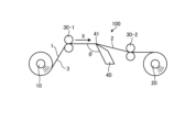
- FIG. 1 is a schematic diagram of a coating stripping apparatus according to a first embodiment of the present invention.
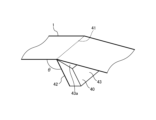
- FIG. 2 is a perspective view for explaining the angle between the coating peeling member and the coated film used in FIG.
- FIG. 3 is a diagram illustrating the angle formed between a coating peeling member and a coated film disclosed in the prior art.
- FIG. 4 is a diagram illustrating an angle formed between the coating peeling member and the coated film according to the first modification of the first embodiment of the present invention.
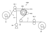
- FIG. 5 is a schematic diagram of a coating stripping device according to a second modification of the first embodiment of the present invention.
- FIG. 6A is a side view of a coating peeling member according to a third modification of the first embodiment of the present invention, and FIG.
- FIG. 6B is a front view seen from the downstream side in the film transport direction.
- FIG. 7 is a schematic diagram of a coating stripping apparatus using the coating stripping member of FIG.
- FIG. 8 is a perspective view of a coating removing member according to a fourth modified example of the first embodiment of the present invention.
- FIG. 9 is a schematic diagram of a coating stripping device according to a fifth modification of the first embodiment of the present invention.
- FIG. 10 is a schematic diagram of a coating stripping device according to a second embodiment of the present invention.
- 11A and 11B are a front view and a side view, respectively, of the rotary peeling member used in FIG.
- FIG. 12 is a schematic diagram of a coating stripping device according to a first modification of the second embodiment of the present invention.
- FIG. 13 is a perspective view of the rotary stripping member used in FIG.
- FIG. 14 is a diagram for explaining coating peeling and ejection by the rotary peeling member shown in FIG.
- FIG. 15 is a schematic diagram of a coating stripping device according to a second modification of the second embodiment of the present invention.
- 16A is a front view of a rotary peeling member according to a third modified example of the second embodiment of the present invention
- FIG. 16B is a view taken along an arrow X in FIG. 16A
- FIG. 16C is a view taken along an arrow Y in FIG.
- FIG. 17 is a perspective view of a rotary peeling member according to a third modification of the second embodiment of the present invention.
- FIG. 18 is a schematic diagram of a coating peeling device according to a fourth modification of the second embodiment of the present invention.
- the coating peeling apparatus 100 includes an unwinding device 10 for unwinding a film 1 having a coating 3 on one side of a base film 2 (hereinafter, sometimes referred to as a coated film), a winding device 20 for winding up the base film 2 after the coating 3 on the surface of the coated film 1 has been peeled off, and driving devices 30-1 and 30-2 for transporting the film in the direction of the arrow X while applying tension to the film.
- the coating peeling apparatus 100 also includes a coating peeling member 40 between the driving devices 30-1 and 30-2 for peeling the coating 3 from the coated film 1.
- the coating peeling apparatus according to the first embodiment will be described below.
- the target coated film 1 has a coating 3 on at least one side of a base film 2.
- the coating 3 include a coating made of an organic substance and a coating made of an inorganic substance.
- the coating made of an inorganic substance include a metal coating provided by vapor deposition and a ceramic green sheet mainly composed of barium titanate.
- the coating made of an organic substance include a coating made of an adhesive such as acrylic, or a fluorine-based or silicone-based release agent provided by coating.
- a coating containing a water-soluble resin that takes into consideration the burden on the environment, etc. is preferable.
- the water-soluble resin a water-soluble polyester resin, polyester urethane resin, acrylic resin, ethylene ionomer resin, polyvinyl alcohol resin, polyvinyl pyrrolidone resin, ethylene-vinyl alcohol resin, and starch are more preferable as the main component.
- a cleaning liquid may be applied to the coating before peeling off the coating 3 by the coating peeling member 40 in the coating peeling apparatus 100E described later.
- the coating containing a water-soluble resin may be a single layer containing a water-soluble resin, a laminate of two or more layers containing a water-soluble resin, or a laminate of a layer containing a water-soluble resin and a layer not containing a water-soluble resin.
- the coating 3 is particularly preferably a release film with a coating that contains a release component in addition to the water-soluble resin in part of the coating, and can efficiently exhibit the effect of peeling off the coating.
- the release component here is a component that increases the contact angle of the coating surface with the cleaning liquid, that is, reduces the surface energy of the coating, and examples of such components include a cured silicone resin compound with dimethylsiloxane as the main skeleton, a compound with a long-chain alkyl group, and a compound with fluorine.
- the coating may be a layer containing a water-soluble resin and a release component, or a layer containing a water-soluble resin and a layer containing a release component may be laminated.
- a layer containing a water-soluble resin directly on the base film, and then a layer containing a release component on the outermost surface.
- a cured silicone resin compound with dimethylsiloxane as the main skeleton, which has high water permeability and can be used suitably as a cleaning liquid, as the release component.
- FIG. 2 is a perspective view for explaining the angle between the coating peeling member 40 used in FIG. 1 and the coated film 1.
- the coating peeling member 40 extends in a ridge-like shape in the film width direction and has a tip 41 that comes into contact with the surface of the coating 3 of the coated film 1 to peel off the coating 3.
- the tip 41 is composed of an upstream surface 42 in the film transport direction, a downstream surface 43 in the film transport direction, and a side surface between the upstream surface 42 and the downstream surface 43.
- the downstream surface 43 in the film transport direction is provided with a slope 43a to make the tip 41 acute angle.
- the coating peeling member 40 is preferably made of metal, but is not limited thereto, and may be made of resin.
- the coating peeling member 40 is installed facing the coating surface of the coated film 1. It is not limited to being installed on the lower surface side as in FIG. 1. It is more preferable that the unwinding device 10 has a mechanism that can switch the unwinding direction of the coated film 1 so that the coating surface of the coated film 1 can be conveyed facing the tip portion 41, so that the coating 3 of the coated film 1 wound in a roll shape can be peeled off regardless of whether the coating 3 is on the inside or outside of the roll.
- the driving devices 30-1 and 30-2 are preferably configured to be able to cut tension so as to stably transport the coated film 1 and the base film 2 from which the coating 3 has been peeled off. If tension is cut using a suction roll, part of the coating of the coated film 1 may be sucked in, which may cause problems, so a configuration in which the driving device is nipped between a metal driving roll and a rubber roll is more preferably used.
- the driving devices 30-1 and 30-2 are preferably made of stainless steel or have been surface-treated to prevent rust.
- Figure 3 is a diagram illustrating the angle between the coating peeling member 40' disclosed in the prior art and the coated film 1.
- the angle ⁇ between the gradient 42a' formed on the surface 42' on the upstream side in the film transport direction among the surfaces constituting the tip portion 41' and the coated film 1 transported toward the tip portion 41' is less than 90° when viewed from the side in the transport direction of the coated film 1.
- the coating peeling member 40 of the present embodiment 1 are arranged so that the angle ⁇ between the surface 42 on the upstream side in the film transport direction among the surfaces constituting the tip portion 41 and the coated film 1 transported toward the tip portion 41 is greater than or equal to 90° and less than 180° when viewed from the side in the transport direction of the coated film.
- the coating 3 can be efficiently peeled off from the coated film 1 without applying high tension to the coated film 1 by the driving devices 30-1 and 30-2. It is more preferable that the angle ⁇ between the surface 42 and the coated film 1 being transported toward the tip 41 is greater than or equal to 90° and less than or equal to 150°.
- the coating peeling device 100 may be provided with an inspection device (not shown) in front of the winding device 20 to detect residues of the coating 3 or environmental foreign matter attached during the process.
- the inspection device may be selected according to the properties of the base film 2, and an inspection device using transmitted light or reflected light is preferably used.
- a marking device (not shown) for recording the position of the coating residue or environmental foreign matter attached during the process detected by the inspection device may be provided between the inspection device and the winding device 20.
- the marking method by the marking device may be any method, such as a pen, sticker, or laser, as long as the position of the detection target can be marked.
- FIG. 4 is a diagram illustrating the angle between the coating peeling member 40A and the coated film 1 according to the first modified example of the first embodiment of the present invention.
- the tip 41A of the coating peeling member 40A has an arc-shaped concave surface 42b on the surface 42A on the upstream side in the film transport direction, and the tip 41A is composed of the concave surface 42b, the slope 43a, and the side surface between the concave surface 42b and the slope 43a.
- the coating 3 can be efficiently peeled off from the coated film 1 without applying high tension by arranging the coating peeling member 40A so that the angle ⁇ between the upstream concave surface 42b in the film transport direction and the coated film 1 transported in the direction of the tip 41A is 90° or more and less than 180°, as viewed from the side in the transport direction of the coated film. It is more preferable that the angle ⁇ between the concave surface 42b and the coated film 1 transported in the direction of the tip 41A is 90° or more and less than 150°.
- FIG. 5 is a schematic diagram of a coating peeling device 100B according to a second modification of the first embodiment of the present invention.
- the coating peeling device 100B includes multiple coating peeling members 40-1, 40-2, and 40-3.
- the coating peeling members 40-1, 40-2, and 40-3 have the same configuration as the coating peeling member 40 according to the first embodiment.
- the coating peeling members 40-1, 40-2, and 40-3 are arranged in the film transport direction between the driving devices 30-1 and 30-2. As with the coating peeling member 40 in embodiment 1, the coating peeling members 40-1, 40-2, and 40-3 are arranged so that the angle ⁇ between the surface 42 on the upstream side of the film transport direction among the surfaces constituting the tip portion 41 and the coated film 1 transported toward the tip portion 41 is 90° or more and less than 180°. By providing multiple coating peeling members 40-1, 40-2, and 40-3, the peeling efficiency of the coating 3 can be further improved. In this modified example, three coating peeling members 40-1, 40-2, and 40-3 are arranged, but the number of coating peeling members arranged is not limited to this.
- angles ⁇ between each coating peeling member and the coated film 1 may all be the same angle or different angles. It is even more preferable that the angle ⁇ between the surface 42 of each coating peeling member and the coated film 1 being transported toward the tip 41 is greater than or equal to 90° and less than or equal to 150°.
- FIG. 6 is a side view (A) and a front view (B) of a coating peeling member 40C according to a third variation of the first embodiment of the present invention, as viewed from the downstream side in the film transport direction.
- FIG. 7 is a schematic diagram of a coating peeling device 100C that uses the coating peeling member 40C of FIG. 6.
- the coating peeling member 40C has a cylindrical body 45 and a plurality of tip portions 41C arranged on the circumference of the body 45 parallel to the central axis of the body 45.
- the tip portion 41C is composed of an upstream surface 42C in the film transport direction, a downstream surface 43C in the film transport direction, and a side surface between the upstream surface 42C and the downstream surface 43C.
- the coating peeling member 40C can also be used by rotating it around the central axis of the body 45 as the rotation axis. When rotating the coating peeling member 40C, it is preferable to rotate it in reverse in the opposite direction to the transport direction of the coated film 1.
- the tip portion 41C is formed on the circumference of the body 45 and the transport direction of the coated film 1 is set so that the angle ⁇ between the upstream surface 42C in the film transport direction of the surfaces constituting the tip portion 41C and the coated film 1 is greater than or equal to 90° and less than 180°. It is even more preferable that the angle between surface 42C and coated film 1 is greater than or equal to 90° and less than or equal to 150°.
- a roller 50 is disposed downstream of the coating peeling member 40C.
- the roller 50 By disposing the roller 50 downstream of the coating peeling member 40C and with multiple tip portions 41C in contact with the coated film 1, the peeling efficiency of the coating 3 can be improved.
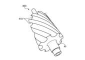
- FIG. 8 is a perspective view of a coating peeling member 40D according to a fourth modified example of the first embodiment of the present invention.
- the coating peeling member 40D has a cylindrical body 45 and a plurality of tip portions 41D arranged in a spiral on the circumference of the body 45.
- the coating peeling member 40D can be used in place of the coating peeling member 40C in the coating peeling device 100C shown in FIG. 7.
- the coating peeling member 40D can also be used by rotating it around the central axis of the body 45 as the rotation axis, like the coating peeling member 40C. When rotating the coating peeling member 40D, it is preferable to rotate it in reverse in the opposite direction to the conveying direction of the coated film 1.
- the tip portion 41D is formed on the circumference of the body 45 and the conveying direction of the coated film 1 is set so that the angle ⁇ between the surface of the tip portion 41D that is upstream of the film conveying direction and the coated film 1 is greater than or equal to 90° and less than 180°. It is even more preferable for the angle ⁇ to be greater than or equal to 90° and less than or equal to 150°.
- FIG. 9 is a schematic diagram of a coating peeling device 100E according to a fifth variation of the first embodiment of the present invention.
- the coating peeling device 100E includes a cleaning liquid application mechanism 60 located upstream of the coating peeling member 40 in the film transport direction.
- the cleaning liquid application mechanism 60 includes a discharge nozzle that discharges the cleaning liquid, a liquid delivery pump that delivers the cleaning liquid to the discharge nozzle, and a tank for storing the cleaning liquid.
- the coating peeling device 100E is preferably used to make it easier to peel off the coating 3.
- the amount of cleaning liquid applied to the coating surface of the coated film 1 is preferably 1 cm3 / m2 or more so that at least a portion of the components of the coating can be sufficiently dissolved, and the specifications of the discharge head and liquid feed pump should be determined so that the liquid feed pump can be adjusted according to the transport speed of the coated film 1 and the required amount of cleaning liquid can be applied to the coating surface of the coated film 1.
- the discharge nozzle may be any nozzle capable of applying the cleaning liquid to the coating surface of the coated film 1, and examples of such nozzles include a spray nozzle, a shower head nozzle, and a high-pressure water jet nozzle.
- the cleaning liquid application mechanism 60 may be capable of applying cleaning liquid to the coating surface of the coated film 1, and may have a liquid tank that stores the cleaning liquid, and the cleaning liquid may be applied to the coating surface by immersing the coated film 1 in the liquid tank.
- the cleaning liquid used in the coating peeling apparatus 100E can be any solvent that can dissolve at least a portion of the components of the coating, but it is preferable to use water in order to reduce the environmental impact.
- a surfactant or the like may be added to the cleaning liquid to improve wettability with the coated film and make it easier for the cleaning liquid to spread over the coating surface.
- the discharge head may be equipped with a heat source such as a cartridge heater, or a tank for storing the cleaning solution may be heated.
- the liquid tank may be heated, or a throw-in heater may be installed inside the liquid tank. Any means capable of heating the cleaning solution may be used, and is not limited to these.
- the coated film 1 to which the cleaning liquid has been applied may be heated.
- a hot air generator or the like (not shown) may be used as a heating means. By raising the temperature of the coated film 1 to 40°C or higher by hot air, the cleaning liquid applied to the coating surface quickly dissolves at least some of the components of the coating, and the coating can be peeled off more efficiently.
- the heating means for the coated film 1 may be any means, for example, the coated film 1 may be directly contacted with a heating roll, or the cleaning liquid application mechanism 60 and the coating peeling mechanism 40 may be surrounded by a booth and heated by installing an infrared heater inside the booth, but is not limited to these.
- the booth by installing a booth, it is possible to prevent the temperature of the heated cleaning liquid and/or the coated film 1 from decreasing, and even if the cleaning liquid is applied in the form of droplets, it is possible to prevent the cleaning liquid from scattering around. Since the inside of the booth becomes hot, it is preferable that the booth has heat resistance, and metal or glass is preferably used.
- the coating peeling device 100E it is more preferable to completely remove the cleaning liquid from the base film 2 after peeling off the coating 3 wound up by the winding device 20, so that it can be remelted and stably produced as a recycled film, and a drying device (not shown) may be provided between the coating peeling member 40 and the winding device 20.
- the drying device may be provided before winding, and may be provided either before or after the driving device 30-2.
- the coating peeling device and coating peeling method according to the first embodiment of the present invention can efficiently peel off a coating from a coated film having a coating on at least one side of a substrate film without applying high tension.
- the coating peeling apparatus 100F includes an unwinding device 10 for unwinding a film 1 having a coating 3 on one side of a base film 2 (hereinafter, sometimes referred to as a coated film), a winding device 20 for winding up the base film 2 after the coating 3 on the surface of the coated film 1 has been peeled off, and driving devices 30-1 and 30-2 for conveying the film in the direction of the arrow X while applying tension to the film.
- an unwinding device 10 for unwinding a film 1 having a coating 3 on one side of a base film 2 (hereinafter, sometimes referred to as a coated film)
- a winding device 20 for winding up the base film 2 after the coating 3 on the surface of the coated film 1 has been peeled off
- driving devices 30-1 and 30-2 for conveying the film in the direction of the arrow X while applying tension to the film.
- the coating peeling apparatus 100F includes a rotary peeling member 40F between the driving devices 30-1 and 30-2 for peeling the coating 3 from the coated film 1, a roller 50 disposed downstream of the rotary peeling member 40F, and a suction mechanism 70 for sucking the coating 3, which is a peeled material peeled off by the coating peeling member 40F.
- the coating peeling apparatus according to the second embodiment will be described below.
- the target coated film 1 has a coating 3 on at least one surface of a base film 2, and is the same as the target coated film 1 according to the first embodiment.
- a cleaning liquid may be applied to the coating before peeling the coating 3 by a coating peeling member 40F in a coating peeling apparatus 100K described below.
- FIG. 11 is a front view (A) and a side view (B) of the rotary peeling member 40F used in FIG. 10.
- the rotary peeling member 40F has a main body 45F having a rotation axis R extending in the width direction of the coated film 1, a plurality of tip portions 41F arranged to extend in a ridge-like manner in the width direction on the circumference of the main body 45F, which contact the surface of the coating 3 to peel off the coating 3, and a discharge portion 44 which is a space between the plurality of tip portions 41F.
- Each of the plurality of tip portions 41F is composed of a surface 411 on the upstream side in the film conveying direction, a surface 412 in the circumferential direction that contacts the base film 2 from which the coating 3 has been peeled off, and a side surface between the upstream surface 411 and the circumferential surface 412.
- the tip portion 41F and the discharge portion 44 are arranged to extend parallel to the rotation axis R on the circumference of the main body 45F.
- the rotary peeling member 40F is preferably formed of metal, but is not limited thereto, and may be made of resin.
- the rotary peeling member 40F is placed opposite the coating surface of the coated film 1.
- the rotary peeling member 40F has a rotation drive means (not shown) and is driven to rotate in reverse, in the opposite direction to the conveying direction of the coated film 1.
- the position of the rotary peeling member 40F is not limited to the bottom side as shown in FIG. 10. It is more preferable that the unwinding device 10 has a mechanism that can switch the unwinding direction of the coated film 1 and convey the coated surface of the coated film 1 opposite the tip 41 so that the coating 3 of the coated film 1 wound in a roll can be peeled off regardless of whether the coating 3 is on the inside or outside of the roll.
- the tip portion 41F is preferably formed such that, when viewed from the side in the transport direction of the coated film 1, the angle between the surface 411 on the upstream side in the film transport direction among the surfaces constituting the tip portion 41F and the coated film transported toward the tip portion is 90° or more and less than 180°.
- the coating 3 can be efficiently peeled off from the coated film 1 without applying high tension to the coated film 1 by the driving devices 30-1, 30-2. It is even more preferable that the angle between the surface 411 and the coated film transported toward the tip portion is 90° or more and 150° or less.
- the driving devices 30-1 and 30-2 are preferably configured to be able to cut tension so as to stably transport the coated film 1 and the base film 2 from which the coating 3 has been peeled off. If tension is cut using a suction roll, part of the coating of the coated film 1 may be sucked in, which may cause problems, so a configuration in which the driving device is nipped between a metal driving roll and a rubber roll is more preferably used.
- the driving devices 30-1 and 30-2 are preferably made of stainless steel or have been surface-treated to prevent rust.
- the roller 50 which is located downstream of the rotating peeling member 40F, is positioned so that multiple tip portions 41 come into contact with the coated film 1. This improves the peeling efficiency of the coating 3 by the coating peeling member 40F.
- the suction mechanism 70 has a tank 72 that stores the sucked coating 3, and a suction device 74 that sucks the peeled coating 3 from the discharge part.
- a vacuum pump or the like can be used as the suction device.
- the discharge part 44 and the tank 72 are connected by a pipe 71, and the tank 72 and the suction device 74 are connected by a pipe 73. Note that the peeling of the coating 3 from the coated film 1 by the tip 41F is performed only at the site where the coated film 1 and the tip 41F contact each other, so the peeled coating 3 may be sucked from the discharge part 44 formed by the surface 411 of the tip 41F that contacts the coated film 1 on the upstream side in the film transport direction.
- the coating peeling device 100F may be provided with an inspection device (not shown) in front of the winding device 20 to detect residues of the coating 3 or environmental foreign matter attached during the process.
- the inspection device may be selected according to the properties of the base film 2, and an inspection device using transmitted light or reflected light is preferably used.
- a marking device (not shown) for recording the position of the coating residue or environmental foreign matter attached during the process detected by the inspection device may be provided between the inspection device and the winding device 20.
- the marking method by the marking device may be any method, such as a pen, sticker, or laser, as long as it can mark the position of the detection target.
- the coating 3 is peeled off from the coated film 1 by the rotating peeling member 40F, and the coating 3 that accumulates in the discharge section 44 is sucked up by the suction mechanism 70, so that even with long-term use, the coating 3 does not accumulate on the rotating peeling member 40F and peeling performance can be maintained.
- FIG. 12 is a schematic diagram of a coating peeling device 100G according to a first modified example of the second embodiment of the present invention
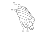
- FIG. 13 is a perspective view of a rotating peeling member 40G used in FIG. 12.
- Coating peeling device 100G differs from coating peeling device 100F in that it includes a rotating peeling member 40G instead of rotating peeling member 40F, and does not include a suction mechanism 70.
- the rotary peeling member 40G has a main body 45G having a rotation axis R extending in the width direction of the coated film 1, a plurality of tip portions 41G arranged to extend in a ridge-like manner in the width direction on the circumference of the main body 45G, which contact the surface of the coating 3 to peel off the coating 3, and a discharge portion 44G which is a space between the plurality of tip portions 41G.
- the plurality of tip portions 41G like the tip portion 41F, are composed of an upstream surface in the film transport direction, a circumferential surface that contacts the base film 2 from which the coating 3 has been peeled off, and a side surface between the upstream surface and the circumferential surface.
- the tip portions 41G and the discharge portion 44G are arranged to extend in a spiral shape on the circumference of the main body 45G.
- the rotary peeling member 40G is preferably made of metal, but is not limited to this and may be made of any material such as resin or rubber. Furthermore, plating or coating may be applied, and may be appropriately selected depending on the material of the coated film 1 and the components of the coating 3.
- tip portion 41G is preferably formed such that, when viewed from the side in the transport direction of coated film 1, the angle between the upstream surface of tip portion 41G in the film transport direction and the coated film transported toward the tip portion is 90° or more and less than 180°, and 90° or more and less than 150° is even more preferable.
- coating 3 can be efficiently peeled off from coated film 1 without applying high tension to coated film 1 by driving devices 30-1 and 30-2.
- FIG. 14 is a diagram illustrating the coating peeling and discharge of the rotating peeling member 40G shown in FIG. 13.
- the rotating peeling member 40G is driven by a rotation drive means (not shown) to rotate in reverse in the direction opposite to the transport direction of the coated film 1.
- the coating 3 peeled off by contact between the coated film 1 and the tip 41G is deposited in the discharge section 44G.
- the discharge section 44G is formed in a spiral shape on the circumference of the main body 45G, so that the coating 3 deposited in the discharge section 44G is discharged from the end of the discharge section 44G downstream in the film transport direction as the rotating peeling member 40G rotates, as shown by the black arrow in FIG. 14.
- the tip 41G and discharge portion 44G may also be arranged on the circumference of the main body 45G so as to extend in a double helical shape that combines right and left twists with the center of the width of the rotating peeling member 40G as the boundary. Since they are symmetrical in the width direction, problems such as meandering are less likely to occur when the coated film 1 is transported.
- the twisting direction toward the center of the width direction is set to be the direction in which the rotating peeling member 40G rotates so that the coating can be discharged to the end of the rotating peeling member 40G.
- a rotating peeling member 40G having a spiral tip 41G and a discharge portion 44G is used, so that the coating can be removed from the rotating peeling member 40G without suction using a suction mechanism, and peeling performance can be maintained even when used for a long period of time.
- FIG. 15 is a schematic diagram of a coating peeling device 100H according to a second modification of the second embodiment of the present invention.
- the coating peeling device 100H includes the rotary peeling device 40G according to the first modification, and is also provided with an air ejection mechanism 80.
- the air blowing mechanism 80 blows air into the discharge section 44G of the rotary peeling device 40G to remove the coating that has accumulated within the discharge section 44G.
- the air blowing mechanism 80 is connected to the discharge section 44G by piping 81. Since the peeling of the coating 3 from the coated film 1 by the tip 41G is performed only at the site where the coated film 1 and the tip 41G contact each other, it is sufficient to blow air into the discharge section 44G that is formed by the surface of the tip 41G that contacts the coated film 1 on the upstream side in the film transport direction.
- the coating 3 in the discharge section 44G of the rotating peeling member 40G can be forcibly discharged by air, so that the coating can be removed from the rotating peeling member 40G and peeling performance can be maintained even after long-term use.
- a suction mechanism 70 may be connected to the rotary peeling member 40G to suck up the peeled coating 3.
- an air blowing mechanism 80 may be connected to the rotary peeling member 40F.
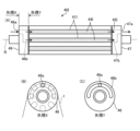
- FIG. 16A is a front view of a rotary peeling member 40I according to a third modified example of the second embodiment of the present invention
- FIG. 16B is an arrow X view in FIG. 16A
- FIG. 16C is an arrow Y view in FIG. 16A.
- the rotary peeling member 40I has a main body 45I having a rotation axis R extending in the width direction of the coated film 1, a plurality of tip portions 41I arranged so as to extend in a ridge-like manner in the width direction on the circumference of the main body 45I and contact the surface of the coating 3 to peel off the coating 3, a discharge portion 44I which is a space between the plurality of tip portions 41I, a first connecting member 46 attached to one end of the main body 45I, and a second connecting member 47 attached to the other end of the main body 45I.
- the first connecting member 46 and the second connecting member 47 are attached to the main body 45I in such a manner that they do not rotate when the main body 45I is rotated by the rotary drive means.
- the main body 45I, the tip portion 41I, and the discharge portion 44I have the same configurations as the main body 45, the tip portion 41F, and the discharge portion 44 of the second embodiment.
- the first connecting member 46 has a connecting portion 46a to which a pipe connected to the air blowing mechanism is connected, and a groove portion 46b that supplies air supplied from the air blowing mechanism via the connecting portion 46a to the discharge portion 44I.
- the groove portion 46b is configured to supply air to five discharge portions.
- the second connection member 47 has a connection part 47a to which a pipe that connects to the suction mechanism is connected, and a groove part 47b that collects the coating discharged together with the air from the discharge part 44I. Air blown out by the air blowing mechanism is supplied to the discharge part 44I by the first connection member 46, and the coating discharged together with the air supplied to the discharge part 44I is collected in the groove part 47b of the second connection member 47, and the coating in the groove part 47b is sucked in by the suction mechanism via the connection part 47a.
- the first connecting member 46 and the second connecting member 47 supply air to the discharge section 44I where the coating accumulates, and the coating is sucked in together with the supplied air, so that the coating can be quickly removed from the rotary peeling member 40I.
- the width of the coated film 1 approximately the same as the width of the rotary peeling member 40I and covering the discharge section 44I with the coated film 1, scattering of the peeled coating can be suppressed and the airtightness of the space in the discharge section 44I is increased, allowing the coating to be removed more quickly.
- the surface forming the discharge section 44I may be coated with a fluorine coating or silicone coating to improve releasability and suppress the accumulation of the coating within the discharge section 44I.
- the rotary peeling member 40I may be made hollow all the way to the end of the shaft, with a hole provided that connects this hollow section to the discharge section 44I.
- the end of the shaft of the rotary peeling member 40I may then be connected to a suction mechanism via a rotary joint, allowing the coating inside the discharge section 44I to be sucked through the hollow section.
- the peeling performance deteriorates when the accumulated coating gets between the tip 41I and the coated film 1. Therefore, it is preferable that the amount of peeled coating near the tip 41I is small, and more preferably, there is no peeled coating; in other words, by quickly and immediately removing any peeled coating, the accumulation of the coating can be prevented and the peeling performance can be maintained even with long-term use.
- FIG. 17 is a diagram illustrating the angle between the tip 41J of the rotary peeling member 40J and the coated film 1 according to the fourth modified example of the second embodiment of the present invention.
- the tip 41J of the rotary peeling member 40J has an arc-shaped surface 411J on the upstream side in the film transport direction.
- the tip 41J of the rotary peeling member 40J is also formed so that the angle ⁇ between the upstream surface 411J in the film transport direction and the coated film 1 is 90° or more and less than 180°, so that the coating 3 can be efficiently peeled off from the coated film 1 without applying high tension. It is even more preferable that the angle between the surface 411J and the coated film 1 is 90° or more and 150° or less.
- FIG. 18 is a schematic diagram of a coating peeling apparatus 100K according to Variation 5 of Embodiment 2 of the present invention.
- the coating peeling apparatus 100K includes a cleaning liquid application mechanism 60 upstream of the peeling member 40G in the film transport direction.
- the cleaning liquid application mechanism 60 may be the same as the cleaning liquid application mechanism 60 used in the coating peeling apparatus 100E according to Variation 5 of Embodiment 1 of the present invention.
- the coating peeling apparatus 100K is preferably used to make it easier to peel off the coating 3.
- the amount of cleaning liquid applied to the coating surface of the coated film 1, the type of cleaning liquid, and the type of discharge nozzle can be the same as those used in the cleaning liquid application mechanism 60 used in the coating peeling apparatus 100E according to variant 5 of embodiment 1 of the present invention.
- the cleaning liquid application mechanism 60 may be capable of applying cleaning liquid to the coating surface of the coated film 1, and may have a liquid tank that stores the cleaning liquid, and the cleaning liquid may be applied to the coating surface by immersing the coated film 1 in the liquid tank.
- the discharge head may be equipped with a heat source such as a cartridge heater, or the tank that stores the cleaning solution may be heated.
- a heat source such as a cartridge heater
- the tank that stores the cleaning solution may be heated.
- the liquid tank may be heated, or a throw-in heater may be installed inside the liquid tank. Any means that can heat the cleaning solution may be used, and is not limited to these.
- the coating peeled off in the above manner contains components dissolved by the cleaning liquid, so it has a high viscosity, has poor fluidity and is prone to accumulation.
- the rotating peeling member 40F of the present invention is used, the peeled off coating is forcibly discharged from the downstream end of the discharge section 44G in the film transport direction as the rotating peeling member 40G rotates, so peeling performance can be maintained without accumulation even with long-term use.
- the rotating peeling member 40G may be replaced by the rotating peeling member 40I according to variant 3, along with an air ejection mechanism and a suction mechanism. Since the coating is sucked in together with the supplied air, the peeled coating is forcibly discharged, and peeling performance can be maintained without accumulation even with long-term use.
- the coated film 1 to which the cleaning liquid has been applied may be heated.
- a hot air generator or the like (not shown) may be used as a heating means. By raising the temperature of the coated film 1 to 40°C or higher by hot air, the cleaning liquid applied to the coating surface quickly dissolves at least some of the components of the coating, and the coating can be peeled off more efficiently.
- the heating means for the coated film 1 may be any means, for example, the coated film 1 may be directly contacted with a heating roll, or the cleaning liquid application mechanism 60 and the coating peeling mechanism 40G may be surrounded by a booth and heated by installing an infrared heater inside the booth, but is not limited to these.
- the booth by installing a booth, it is possible to prevent the temperature of the heated cleaning liquid and/or the coated film 1 from decreasing, and even if the cleaning liquid is applied in the form of droplets, it is possible to prevent the cleaning liquid from scattering around. Since the inside of the booth becomes hot, it is preferable that the booth has heat resistance, and metal or glass is preferably used.
- the coating peeling device 100K it is more preferable to completely remove the cleaning liquid from the base film 2 after peeling off the coating 3 wound up by the winding device 20, so that it can be remelted and stably produced as a recycled film, and a drying device (not shown) may be provided between the rotating peeling member 40G and the winding device 20.
- the drying device may be provided before winding, and may be provided either before or after the driving device 30-2.
Landscapes
- Engineering & Computer Science (AREA)
- Environmental & Geological Engineering (AREA)
- Mechanical Engineering (AREA)
- Manufacturing & Machinery (AREA)
- Application Of Or Painting With Fluid Materials (AREA)
- Folding Of Thin Sheet-Like Materials, Special Discharging Devices, And Others (AREA)
- Coating Apparatus (AREA)
Priority Applications (4)
| Application Number | Priority Date | Filing Date | Title |
|---|---|---|---|
| JP2024522632A JPWO2024247486A1 (https=) | 2023-05-31 | 2024-04-04 | |
| CN202480026628.0A CN121057643A (zh) | 2023-05-31 | 2024-04-04 | 被膜剥离装置及被膜剥离方法 |
| EP24814973.4A EP4721944A1 (en) | 2023-05-31 | 2024-04-04 | Coating peeling device and coating peeling method |
| KR1020257033889A KR20260018785A (ko) | 2023-05-31 | 2024-04-04 | 피막 박리 장치 및 피막 박리 방법 |
Applications Claiming Priority (4)
| Application Number | Priority Date | Filing Date | Title |
|---|---|---|---|
| JP2023-089859 | 2023-05-31 | ||
| JP2023090015 | 2023-05-31 | ||
| JP2023-090015 | 2023-05-31 | ||
| JP2023089859 | 2023-05-31 |
Publications (1)
| Publication Number | Publication Date |
|---|---|
| WO2024247486A1 true WO2024247486A1 (ja) | 2024-12-05 |
Family
ID=93657700
Family Applications (1)
| Application Number | Title | Priority Date | Filing Date |
|---|---|---|---|
| PCT/JP2024/013876 Ceased WO2024247486A1 (ja) | 2023-05-31 | 2024-04-04 | 被膜剥離装置および被膜剥離方法 |
Country Status (6)
| Country | Link |
|---|---|
| EP (1) | EP4721944A1 (https=) |
| JP (1) | JPWO2024247486A1 (https=) |
| KR (1) | KR20260018785A (https=) |
| CN (1) | CN121057643A (https=) |
| TW (1) | TW202513255A (https=) |
| WO (1) | WO2024247486A1 (https=) |
Cited By (1)
| Publication number | Priority date | Publication date | Assignee | Title |
|---|---|---|---|---|
| JP7768616B1 (ja) * | 2025-04-04 | 2025-11-12 | 株式会社Pntecソリューション | 廃棄プラスティックフィルムの残存層剥離装置及び当該装置を用いた廃棄プラスティックフィルムの再生装置並びにこれらの方法 |
Citations (6)
| Publication number | Priority date | Publication date | Assignee | Title |
|---|---|---|---|---|
| JPH11179335A (ja) * | 1997-12-22 | 1999-07-06 | Kanegafuchi Chem Ind Co Ltd | 積層体の層の剥離方法 |
| JP2000206844A (ja) * | 1999-01-19 | 2000-07-28 | Ricoh Co Ltd | 被記録材の再生装置 |
| JP2001259538A (ja) * | 2000-03-21 | 2001-09-25 | Chuki Seiki Kk | フィルムから付着物を除去する方法及びその装置 |
| JP2011251501A (ja) * | 2010-06-04 | 2011-12-15 | Kyoto Kankyo Hozen Kosha:Kk | 熱可塑性樹脂シートの分離方法及び分離装置 |
| JP2017056675A (ja) | 2015-09-18 | 2017-03-23 | 株式会社パンテック | 帯状フィルムの被膜剥離装置 |
| WO2022190713A1 (ja) | 2021-03-12 | 2022-09-15 | 東レ株式会社 | 被膜付きフィルムからの被膜の剥離方法および被膜の剥離装置 |
-
2024
- 2024-04-04 JP JP2024522632A patent/JPWO2024247486A1/ja active Pending
- 2024-04-04 WO PCT/JP2024/013876 patent/WO2024247486A1/ja not_active Ceased
- 2024-04-04 CN CN202480026628.0A patent/CN121057643A/zh active Pending
- 2024-04-04 KR KR1020257033889A patent/KR20260018785A/ko active Pending
- 2024-04-04 EP EP24814973.4A patent/EP4721944A1/en active Pending
- 2024-05-24 TW TW113119225A patent/TW202513255A/zh unknown
Patent Citations (6)
| Publication number | Priority date | Publication date | Assignee | Title |
|---|---|---|---|---|
| JPH11179335A (ja) * | 1997-12-22 | 1999-07-06 | Kanegafuchi Chem Ind Co Ltd | 積層体の層の剥離方法 |
| JP2000206844A (ja) * | 1999-01-19 | 2000-07-28 | Ricoh Co Ltd | 被記録材の再生装置 |
| JP2001259538A (ja) * | 2000-03-21 | 2001-09-25 | Chuki Seiki Kk | フィルムから付着物を除去する方法及びその装置 |
| JP2011251501A (ja) * | 2010-06-04 | 2011-12-15 | Kyoto Kankyo Hozen Kosha:Kk | 熱可塑性樹脂シートの分離方法及び分離装置 |
| JP2017056675A (ja) | 2015-09-18 | 2017-03-23 | 株式会社パンテック | 帯状フィルムの被膜剥離装置 |
| WO2022190713A1 (ja) | 2021-03-12 | 2022-09-15 | 東レ株式会社 | 被膜付きフィルムからの被膜の剥離方法および被膜の剥離装置 |
Non-Patent Citations (1)
| Title |
|---|
| See also references of EP4721944A1 |
Cited By (1)
| Publication number | Priority date | Publication date | Assignee | Title |
|---|---|---|---|---|
| JP7768616B1 (ja) * | 2025-04-04 | 2025-11-12 | 株式会社Pntecソリューション | 廃棄プラスティックフィルムの残存層剥離装置及び当該装置を用いた廃棄プラスティックフィルムの再生装置並びにこれらの方法 |
Also Published As
| Publication number | Publication date |
|---|---|
| JPWO2024247486A1 (https=) | 2024-12-05 |
| TW202513255A (zh) | 2025-04-01 |
| KR20260018785A (ko) | 2026-02-09 |
| EP4721944A1 (en) | 2026-04-08 |
| CN121057643A (zh) | 2025-12-02 |
Similar Documents
| Publication | Publication Date | Title |
|---|---|---|
| US20240149581A1 (en) | Method for removing coating from coated film and equipment for removing coating | |
| JP5106339B2 (ja) | 液滴吐出装置 | |
| WO2024247486A1 (ja) | 被膜剥離装置および被膜剥離方法 | |
| JP2012116093A (ja) | インクジェット記録装置 | |
| JP4894962B1 (ja) | 円筒部材の製造方法 | |
| TWI913410B (zh) | 從附有被膜之薄膜的被膜剝離方法及被膜剝離裝置 | |
| WO2025004534A1 (ja) | 被膜剥離装置および被膜剥離方法 | |
| US20250026902A1 (en) | Coating film removing method and coating film removing equipment for removing coating film from coated film | |
| JP2023143772A (ja) | 被膜剥離装置および被膜剥離方法 | |
| JP2024020963A (ja) | 付着物除去装置、付着物除去方法、シート部材のリサイクル方法及び電子部品の製造方法 | |
| JP7782301B2 (ja) | 被膜付きフィルムからの被膜の剥離装置 | |
| JP2024173758A (ja) | 被膜除去装置および被膜除去方法 | |
| JP7826784B2 (ja) | 被膜剥離装置および被膜剥離方法 | |
| EP4549119A1 (en) | Coating detachment mechanism and coating detachment device | |
| CN114126774A (zh) | 用液体处理凸版印刷版前体的装置和方法 | |
| JP2003290699A (ja) | ウエブ冷却装置 | |
| TW202348386A (zh) | 被膜剝離裝置及被膜剝離方法 | |
| JP2024020961A (ja) | 付着物除去装置、付着物除去方法、シート部材のリサイクル方法及び電子部品の製造方法 | |
| JP7753909B2 (ja) | 被膜付きフィルムからの被膜の剥離装置および被膜の剥離方法 | |
| CN117505389A (zh) | 附着物去除装置、附着物去除方法、片构件的再利用方法及电子部件的制造方法 | |
| WO2023218811A1 (ja) | 被膜剥離方法および被膜剥離装置 | |
| JP2007069125A (ja) | 塗布装置及び塗布方法 | |
| JP2014132611A (ja) | 成膜物の製造方法、成膜装置 | |
| JP2004105926A (ja) | 塗布装置の洗浄方法及び洗浄装置 | |
| JP2010159132A (ja) | 搬送ベルトの製造方法 |
Legal Events
| Date | Code | Title | Description |
|---|---|---|---|
| WWE | Wipo information: entry into national phase |
Ref document number: 2024522632 Country of ref document: JP |
|
| 121 | Ep: the epo has been informed by wipo that ep was designated in this application |
Ref document number: 24814973 Country of ref document: EP Kind code of ref document: A1 |
|
| WWE | Wipo information: entry into national phase |
Ref document number: 2501007871 Country of ref document: TH |
|
| WWE | Wipo information: entry into national phase |
Ref document number: 11202506974V Country of ref document: SG |
|
| WWP | Wipo information: published in national office |
Ref document number: 11202506974V Country of ref document: SG |
|
| NENP | Non-entry into the national phase |
Ref country code: DE |
|
| WWE | Wipo information: entry into national phase |
Ref document number: 2024814973 Country of ref document: EP |
|
| ENP | Entry into the national phase |
Ref document number: 2024814973 Country of ref document: EP Effective date: 20260102 |
|
| ENP | Entry into the national phase |
Ref document number: 2024814973 Country of ref document: EP Effective date: 20260102 |
|
| ENP | Entry into the national phase |
Ref document number: 2024814973 Country of ref document: EP Effective date: 20260102 |
|
| ENP | Entry into the national phase |
Ref document number: 2024814973 Country of ref document: EP Effective date: 20260102 |
|
| ENP | Entry into the national phase |
Ref document number: 2024814973 Country of ref document: EP Effective date: 20260102 |
|
| ENP | Entry into the national phase |
Ref document number: 2024814973 Country of ref document: EP Effective date: 20260102 |
|
| WWP | Wipo information: published in national office |
Ref document number: 2024814973 Country of ref document: EP |