WO2024247328A1 - 自動培養装置、自動培養システム - Google Patents
自動培養装置、自動培養システム Download PDFInfo
- Publication number
- WO2024247328A1 WO2024247328A1 PCT/JP2023/045673 JP2023045673W WO2024247328A1 WO 2024247328 A1 WO2024247328 A1 WO 2024247328A1 JP 2023045673 W JP2023045673 W JP 2023045673W WO 2024247328 A1 WO2024247328 A1 WO 2024247328A1
- Authority
- WO
- WIPO (PCT)
- Prior art keywords
- culture
- gas
- automatic culture
- automatic
- culture vessel
- Prior art date
- Legal status (The legal status is an assumption and is not a legal conclusion. Google has not performed a legal analysis and makes no representation as to the accuracy of the status listed.)
- Ceased
Links
Images


Classifications
-
- C—CHEMISTRY; METALLURGY
- C12—BIOCHEMISTRY; BEER; SPIRITS; WINE; VINEGAR; MICROBIOLOGY; ENZYMOLOGY; MUTATION OR GENETIC ENGINEERING
- C12M—APPARATUS FOR ENZYMOLOGY OR MICROBIOLOGY; APPARATUS FOR CULTURING MICROORGANISMS FOR PRODUCING BIOMASS, FOR GROWING CELLS OR FOR OBTAINING FERMENTATION OR METABOLIC PRODUCTS, i.e. BIOREACTORS OR FERMENTERS
- C12M41/00—Means for regulation, monitoring, measurement or control, e.g. flow regulation
- C12M41/48—Automatic or computerized control
-
- C—CHEMISTRY; METALLURGY
- C12—BIOCHEMISTRY; BEER; SPIRITS; WINE; VINEGAR; MICROBIOLOGY; ENZYMOLOGY; MUTATION OR GENETIC ENGINEERING
- C12M—APPARATUS FOR ENZYMOLOGY OR MICROBIOLOGY; APPARATUS FOR CULTURING MICROORGANISMS FOR PRODUCING BIOMASS, FOR GROWING CELLS OR FOR OBTAINING FERMENTATION OR METABOLIC PRODUCTS, i.e. BIOREACTORS OR FERMENTERS
- C12M23/00—Constructional details, e.g. recesses, hinges
- C12M23/38—Caps; Covers; Plugs; Pouring means
-
- C—CHEMISTRY; METALLURGY
- C12—BIOCHEMISTRY; BEER; SPIRITS; WINE; VINEGAR; MICROBIOLOGY; ENZYMOLOGY; MUTATION OR GENETIC ENGINEERING
- C12M—APPARATUS FOR ENZYMOLOGY OR MICROBIOLOGY; APPARATUS FOR CULTURING MICROORGANISMS FOR PRODUCING BIOMASS, FOR GROWING CELLS OR FOR OBTAINING FERMENTATION OR METABOLIC PRODUCTS, i.e. BIOREACTORS OR FERMENTERS
- C12M27/00—Means for mixing, agitating or circulating fluids in the vessel
- C12M27/16—Vibrating; Shaking; Tilting
-
- C—CHEMISTRY; METALLURGY
- C12—BIOCHEMISTRY; BEER; SPIRITS; WINE; VINEGAR; MICROBIOLOGY; ENZYMOLOGY; MUTATION OR GENETIC ENGINEERING
- C12M—APPARATUS FOR ENZYMOLOGY OR MICROBIOLOGY; APPARATUS FOR CULTURING MICROORGANISMS FOR PRODUCING BIOMASS, FOR GROWING CELLS OR FOR OBTAINING FERMENTATION OR METABOLIC PRODUCTS, i.e. BIOREACTORS OR FERMENTERS
- C12M29/00—Means for introduction, extraction or recirculation of materials, e.g. pumps
- C12M29/06—Nozzles; Sprayers; Spargers; Diffusers
-
- C—CHEMISTRY; METALLURGY
- C12—BIOCHEMISTRY; BEER; SPIRITS; WINE; VINEGAR; MICROBIOLOGY; ENZYMOLOGY; MUTATION OR GENETIC ENGINEERING
- C12M—APPARATUS FOR ENZYMOLOGY OR MICROBIOLOGY; APPARATUS FOR CULTURING MICROORGANISMS FOR PRODUCING BIOMASS, FOR GROWING CELLS OR FOR OBTAINING FERMENTATION OR METABOLIC PRODUCTS, i.e. BIOREACTORS OR FERMENTERS
- C12M41/00—Means for regulation, monitoring, measurement or control, e.g. flow regulation
- C12M41/12—Means for regulation, monitoring, measurement or control, e.g. flow regulation of temperature
- C12M41/14—Incubators; Climatic chambers
-
- C—CHEMISTRY; METALLURGY
- C12—BIOCHEMISTRY; BEER; SPIRITS; WINE; VINEGAR; MICROBIOLOGY; ENZYMOLOGY; MUTATION OR GENETIC ENGINEERING
- C12M—APPARATUS FOR ENZYMOLOGY OR MICROBIOLOGY; APPARATUS FOR CULTURING MICROORGANISMS FOR PRODUCING BIOMASS, FOR GROWING CELLS OR FOR OBTAINING FERMENTATION OR METABOLIC PRODUCTS, i.e. BIOREACTORS OR FERMENTERS
- C12M41/00—Means for regulation, monitoring, measurement or control, e.g. flow regulation
- C12M41/12—Means for regulation, monitoring, measurement or control, e.g. flow regulation of temperature
- C12M41/18—Heat exchange systems, e.g. heat jackets or outer envelopes
- C12M41/24—Heat exchange systems, e.g. heat jackets or outer envelopes inside the vessel
-
- C—CHEMISTRY; METALLURGY
- C12—BIOCHEMISTRY; BEER; SPIRITS; WINE; VINEGAR; MICROBIOLOGY; ENZYMOLOGY; MUTATION OR GENETIC ENGINEERING
- C12M—APPARATUS FOR ENZYMOLOGY OR MICROBIOLOGY; APPARATUS FOR CULTURING MICROORGANISMS FOR PRODUCING BIOMASS, FOR GROWING CELLS OR FOR OBTAINING FERMENTATION OR METABOLIC PRODUCTS, i.e. BIOREACTORS OR FERMENTERS
- C12M41/00—Means for regulation, monitoring, measurement or control, e.g. flow regulation
- C12M41/30—Means for regulation, monitoring, measurement or control, e.g. flow regulation of concentration
- C12M41/34—Means for regulation, monitoring, measurement or control, e.g. flow regulation of concentration of gas
Definitions
- the present invention relates to an automatic culture device for culturing cells or tissues, and in particular to an automatic culture device that can be made small, and an automatic culture system that uses multiple such devices.
- the most common treatment target is cancer, followed by various organs. This is thought to be because autologous transplants, which use the patient's own cells, have a low risk of rejection, and are in high demand from the perspective of improving patients' quality of life (QOL).
- QOL quality of life
- the most common cell type is immune cells, accounting for more than 40% of the total.
- the main target disease is cancer, and specific cell types include T cells, NK cells, and NKT cells.
- CAR-T (chimeric antigen receptor-T) cell therapy has been put to practical use, in which T cells, which are immune cells, are extracted from the patient, processed by gene transfer into a form that can attack cancer cells, and then returned to the patient by injection.
- CPC Cell Processing Center
- SOPs Standard Operating Procedures
- GMP Good Manufacturing Practice
- an automatic culture device there is a device that automatically handles a closed flow path with a closed space, as shown in Patent Document 1.
- a closed culture vessel In the closed flow path, a closed culture vessel is constantly connected by a flow path tube or the like, and cells are cultured inside the closed culture vessel.
- the closed flow path allows the movement of liquids and gases contained within it by operating valves, pumps, etc. installed outside. This allows the automated culture device to automatically perform cell seeding, medium replacement, microscope observation, etc. while maintaining the closed nature of the culture space.
- culture can be performed in a closed culture vessel, but in order to perform culture, the culture vessel is held in a CO2 incubator in which a constant CO2 gas concentration is maintained inside.
- Gas exchange is performed by dissolving gas in the space above the medium in the culture vessel into the medium, or by releasing gas in the medium into the space.
- CO2 incubators are large in order to ensure airtightness in order to keep the internal space filled with gas, and therefore it is difficult to miniaturize an automatic culture device using this configuration.
- CO2 incubators pose the risk of microbial growth due to humidification, making their use difficult in facilities for manufacturing cells for transplantation, which require high levels of cleanliness.
- the object of the present invention is to provide an automatic culture device that can be made compact and save space, allowing multiple devices to be operated simultaneously, and an automatic culture system that uses multiple such devices.
- the automatic culture device is capable of accommodating a culture vessel, and is characterized by comprising a temperature maintaining mechanism for maintaining the culture vessel at a predetermined temperature, a gas supply unit for supplying humidified CO2 gas, and a ventilation adapter that is attached to the culture vessel and supplies humidified CO2 gas from the gas supply unit to the culture vessel.
- the present invention provides an automatic culture device that can be made compact and save space, allowing multiple devices to operate simultaneously, and an automatic culture system that uses multiple devices.
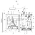
- FIG. 1 is a diagram showing one configuration of an automatic culture device according to a first embodiment.
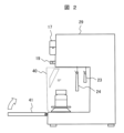
- FIG. 2 is a side view showing one configuration of the automatic culture device according to the first embodiment.
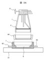
- FIG. 2 is a diagram showing an example of a ventilation adaptor according to the first embodiment.
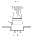
- FIG. 2 is a diagram showing an example of a ventilation adaptor according to the first embodiment.
- FIG. 2 is a diagram showing an example of a ventilation adaptor according to the first embodiment.
- FIG. 2 is a top view of the ventilation adapter according to the first embodiment.
- FIG. 13 is a diagram showing the results of gas exchange in a culture vessel using a ventilation adapter in Example 1.
- FIG. 2 is a diagram showing an example of a flow path circuit including a closed culture vessel according to Example 1.
- FIG. 2 is a diagram showing an example of a cell seeding procedure according to Example 1.
- FIG. 4 is a diagram showing an example of a gas exchange procedure according to the first embodiment.
- FIG. 1 is a diagram showing an example of a procedure for adding a medium according to Example 1.
- FIG. 1 is a diagram showing an example of a procedure for changing a culture medium according to Example 1.
- FIG. 2 is a diagram showing an example of a procedure for supernatant sampling according to Example 1.
- FIG. 2 is a diagram showing an example of a cell recovery procedure according to Example 1.
- FIG. 13 is a diagram showing the state of inclination of the culture vessel during cell recovery in Example 1.
- FIG. 2 is a diagram showing a flow of operation of the automatic culture device according to the first embodiment.
- FIG. 1 is a diagram showing an example of a procedure for adding a medium according to Example 1.
- FIG. 1 is a diagram showing an example of a procedure for changing a culture medium according to Example 1.
- FIG. 2 is
- FIG. 11 is a diagram showing an example of a ventilation adaptor for a flask culture vessel according to Example 2.
- FIG. 1 is a diagram showing an example of an automatic culture system in which a plurality of automatic culture devices according to Example 1 are connected in parallel and controlled by a central management PC.
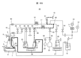
- the automatic culture device 100 includes a culture vessel 1, a ventilation adapter 7, a gas supply unit 9, a pump for supplying liquid or gas or for supplying air, flow paths connecting these, valves for opening and closing the flow paths, a control unit 38 for controlling the gas supply unit, the pump, and the valves, a rocking mechanism 30 for rocking the culture vessel 1, and an incubator 35 as a temperature holding mechanism for housing the culture vessel, the ventilation adapter, the rocking mechanism, and the like and controlling the temperature.
- the culture vessel 1 is a culture vessel with a ventilation surface having a ventilation surface 4 with a gas-permeable membrane disposed on the bottom surface, in which cells 2 are held and cultured together with the medium 3.
- a pressure adjustment tube 5 and a vent filter 6 are connected to the culture vessel 1, allowing gas to enter and exit the culture vessel while preventing the intrusion of bacteria and viruses from the outside.
- the culture vessel 1 is attached to a ventilation adapter 7, so that gases necessary for culture can be supplied and exchanged to the culture vessel 1.
- the gas supply unit 9 is composed of a gas cylinder 10 that holds a predetermined gas concentration, a gas flow control unit (mass flow controller: MF) 11, a pressure sensor 12, and a humidification bottle 13 that is a humidification unit, and is connected upstream of the ventilation adapter 7.
- a CO2 sensor 14 and a CO2 gas vent filter 15 are connected downstream of the ventilation adapter 7, and the gas is discharged to the atmosphere outside the device.
- the CO2 sensor 14 can be used to monitor whether gas exchange in the ventilation adapter is being performed properly, and can also be used to predict the culture state.
- the liquid or gas is fed by pumps 16 and 17, and a suitable pump is a tube pump which generates pressure by squeezing a rubber tube with a rotating roller.
- the pump 16 is configured to deliver the culture medium to the culture vessel 1 , and is connected to a liquid delivery pipe 18 of the culture vessel 1 at one end and to a supply pipe of a culture medium bottle 20 via an electromagnetic valve 19 .
- An electromagnetic valve is suitable for opening and closing the rubber tube that makes up the flow path.
- electricity is applied to the closed state of the rubber tube that is clamped in the valve actuated by spring force, the electromagnetic valve operates and the rubber tube can be controlled to open.
- the pump 17 is configured to pump cell suspension into the culture vessel 1 for cell seeding, to discharge the culture medium 3 from the culture vessel 1, and to recover the proliferated cells.
- the pump 17 is connected to a suction tube 21 of the culture vessel 1, and the other end is connected to a cell seeding bottle 22 via a solenoid valve 19, and to a supernatant collection bag 23 and a supernatant analysis bag 24 via another solenoid valve 19.
- the pump 17 is also connected to a cell collection pipe 25 in the culture vessel 1 through a tube, and the other end is connected to a cell collection bottle 26 via an electromagnetic valve 19.
- the weight of the culture medium bottle 20 is measured by a weight sensor 27, and the weights of the cell seeding bottle 22 and cell collection bottle 26 are measured by a weight sensor 28.
- the medium bottle, cell seeding bottle, cell collection bottle, supernatant collection bag, supernatant analysis bag, flow paths connecting each component, pumps, solenoid valves, and weight sensors are provided in the fluid control unit 29, which is the main body of the device outside the incubator 35.
- the oscillation mechanism 30 consists of an oscillation stage 31 that holds the ventilation adapter 7, a link mechanism 32 that supports the oscillation stage from three directions, oscillation shafts 33 that are connected to the link mechanisms 32, and an oscillation stage fixing mechanism 34 that is fixed inside the incubator.
- the culture vessel is oscillated left to right on the paper, the right oscillating axis is lowered downward and the left oscillating axis is raised upward at the same time. If this is controlled without moving the central oscillating axis, the oscillating stage will move with an inclination and the culture vessel can be tilted. If the movement of the left and right axes is then reversed, the culture vessel can be tilted in the opposite direction.
- the culture vessel By operating these continuously and moving the oscillation axis in the depth direction of the paper, the culture vessel can be tilted back and forth, so the cells 2 and medium 3 inside the culture vessel 1 can be agitated.
- the incubator 35 is an example of a temperature maintaining mechanism, and is a so-called dry incubator consisting of a thermostatic unit 36 and an opening/closing door 37.
- the incubator 35 can accommodate the culture vessel 1, the rocking mechanism 30, and the humidifying bottle 13, and can maintain the temperature inside the incubator at a suitable temperature for cell culture.
- a small dry incubator instead of a large CO2 incubator and having a configuration that can supply gas necessary for culture, the device can be made smaller, and multiple devices can be operated simultaneously in a small space.
- the control unit 38 can control the operation of the gas supply unit 9, pumps 16, 17, and solenoid valve 19, and the operation of the rocking mechanism 30.
- a cell suspension is sent from the cell seeding bottle 22 to the culture vessel 1, during gas exchange, humidified gas from the humidification bottle 13 is supplied to the ventilation adapter 7, during culture medium addition, culture medium is sent from the culture medium bottle 20 to the culture vessel 1, during culture medium replacement, the culture medium 3 in the culture vessel 1 is discharged into the supernatant collection bag 23 and then the culture medium is supplied to the culture vessel 1, and during supernatant sampling, a portion of the culture medium in the culture vessel can be sent to the supernatant analysis bag 24.
- the medium in the culture vessel 1 is discharged into the supernatant collection bag 23, and then the rocking mechanism 30 is operated to stir the cell suspension, which can then be sent to the cell collection bottle 26.
- Figure 2 is a right side view of the device described in Example 1.
- Side covers 40 are provided on the left and right sides of the device, and a bottle unit door 41 that can be opened and closed in the horizontal and vertical directions is provided on the front of the device.
- the side cover 40 shields the movement of gas in the entire space in which the culture medium bottle 20, cell seeding bottle 22, and cell recovery bottle 26 are placed on the weight sensors 27, 28 and weighed, and acts as a wind shield to ensure stable weighing.
- the bottle unit door 41 is open when in a horizontal position, and acts as a stand on which bottles and tubes can be temporarily placed when installing a flow path consisting of bottles and tubes. After the flow path tubes are connected to pumps and valves, it can be closed vertically and used as a windshield.
- the bottle unit door 41 and the opening and closing door 37 of the incubator 35 described above open and close in different directions, allowing the two doors to open and close without interfering with each other, making it easy to access the equipment during work.
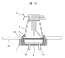
- the ventilation adaptor 7 is placed on a rocking stage 31, and is connected to an air supply pipe 42 connected to the humidifying bottle 13 and an exhaust pipe 43 connected to a CO2 sensor.
- the culture vessel 1 is tightly attached to the ventilation adaptor 7 on a horizontal stand (not shown) by being pressed against the rubber packing 44 mainly due to the weight of the culture vessel 1 and the elasticity of the rubber packing 44.
- a predetermined gas space 8 is formed below the culture vessel 1 and inside the ventilation adaptor 7.
- FIG. 3A shows an example of a ventilation adapter in which CO2 gas is supplied from the outer circumferential side of the ventilation adapter 7 and exhausted from the outer circumferential side.
- This type of ventilation adapter has the advantage that it can be made small in height.
- the contact state between the ventilation adapter 7 and the rubber packing 44 will be described.
- the gas space 8 of the ventilation adapter 7 holds humidified CO2 gas, and in order to reduce leakage of this humidified CO2 gas from the gap between the ventilation adapter 7 and the rubber packing 44, a highly airtight structure is desirable.
- the internal space of the ventilation adapter 7 is maintained at a pressure slightly higher than atmospheric pressure. In other words, the internal space of the ventilation adapter 7 is at a positive pressure compared to atmospheric pressure. This reduces the risk of bacteria in the air entering the internal space of the ventilation adapter 7.
- the volume of the internal space of the ventilation adapter 7 is preferably as small as possible, provided that the volume is large enough to supply humidified CO2 gas uniformly to the gas permeable membrane of the culture vessel. If the volume of the internal space is large, it takes a long time to fill the internal space with humidified CO2 gas.
- the internal space is as thin as possible from top to bottom and has an area in the horizontal direction that is equal to or slightly larger than the area of the gas permeable membrane of the culture vessel.
- the space shape is circular if the vessel is cylindrical, and square if the vessel is square.
- Fig. 3B shows a ventilation adapter that supplies CO2 gas from the bottom and exhausts it from the bottom.
- Fig. 3B shows the state before the installation of the culture vessel 1, rubber packing 44, and ventilation adapter 7, and
- Fig. 3C shows the state during use.
- This type of ventilation adapter is characterized in that the internal space of the ventilation adapter 7 can be made smaller than that of the type shown in Fig. 3A.
- the cross-sectional shape of the rubber packing 44 is shaped to follow the outer periphery of the culture vessel in order to increase the airtightness of the rubber packing 44 and the culture vessel.
- the rubber packing 44 is tightly attached to the ventilation adapter 7 by utilizing the elasticity of the rubber packing.
- the shape of the ventilation adapter can be appropriately selected according to the required specifications of the culture device (size of the culture vessel, culture speed, etc.). In addition to the shapes shown in Figures 3A and 3B, it is also possible to supply CO2 gas from the outside of the circumference and provide an exhaust pipe on the bottom.
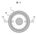
- FIG. 4 is a top view of the ventilation adaptor 7 in the shape of FIG. 3A.
- the internal space of the ventilation adaptor 7 is a circle slightly larger than the circular gas permeable membrane provided in the culture vessel when viewed from above.
- there is one air supply tube 42 for humidified CO2 gas but the air supply tube may be divided into multiple tubes so that the humidified CO2 gas can be supplied to the internal space as uniformly as possible, or the opening may be one large opening.
- the air supply tube 42 is not limited to being connected to the side of the ventilation adaptor 7, but may be connected from the bottom.
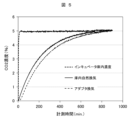
- FIG. 5 shows the results of comparing the time change in the CO 2 gas concentration in the gas phase inside the culture vessel in Example 1 using two measurement methods: a ventilation method using the ventilation adapter 7 and a ventilation method using a 5% CO 2 incubator.
- a CO2 sensor (VISSLA GM70 handheld CO2 meter) (not shown) was installed inside the closed culture vessel 1, and the vent filter 6 was temporarily closed to create a vessel where gas could only pass through the ventilation surface (gas permeable membrane) 4.
- the volume of the gas space 8 was set to 300 cc, and a 5% CO2 -air mixed gas was continuously supplied from the air supply pipe 42 at a flow rate of 50 cc/min.
- a CO2 sensor was placed inside the incubator, which was constantly maintained with 5% CO2 - air, and at the same time, a separate CO2 sensor was placed inside the closed system culture vessel 1, creating a vessel in which the only surface through which gas could pass was the ventilation surface (gas permeable membrane) 4. The measurements were taken over a period of 15 hours when each was kept at 37°C.
- both the CO2 incubator ventilation method and the ventilation adapter ventilation method reached a CO2 concentration of 5% in 800 minutes.
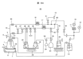
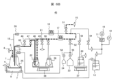
- FIG. 6A is a diagram showing an example of a flow path circuit 45 including a closed culture vessel according to Example 1.
- the same elements as those in the example shown in FIG. 1 are given the same numbers, and the solenoid valves 19 are numbered 46 to 54 for the unique solenoid valves-1 to -9, respectively.
- the rubber tube connected to the supernatant collection bag 23 is equipped with a manual valve 55 that can be used to manually open and close the tube, and the rubber tube connected to the supernatant analysis bag 24 is equipped with a manual valve 56.
- 59 is a connecting part that allows the connection and disconnection of the pipeline by connecting a male and female type.
- 60 is a branching part, which is the branching point of the tubes connected using a T-shaped connecting part.
- the flow path circuit 45 shown here is removable as a unit from the device body shown in Example 1, except for the solenoid valve 19 in the pumps 16 and 17, which are mechanical elements, the weight sensor (electronic balance) 28, the gas flow control unit 11, and the pressure sensor 12, and can be used for cell culture by sterilizing only the flow path circuit.
- FIG. 8 is a flowchart showing the overall operation of cell culture in the cell culture device 100 shown in FIG. 6A. Following “START,” a flow path is installed in the cell culture device 100 (S01), and then the cell seeding bottle 22 that holds a separately prepared cell suspension, the culture medium bottle 20 that holds the culture medium, and the cell recovery bottle 26 are connected to the flow path (S02).
- Fig. 6B shows the cell seeding process according to Example 1.
- the pump is stopped and the rollers are stopped by pinching the rubber tube, so the pumps 16 and 17 are in a closed state as valves.
- the solenoid valve is in a closed state by pinching the rubber tube.
- the cell seeding bottle 22 holds a predetermined amount of cell suspension and is placed on the weight sensor 28, and the culture vessel 1 is placed horizontally on the ventilation adapter 7 with the inside empty.
- the solenoid valves 47, 48, 54 and 51 are opened, and the suction tube 21 of the culture vessel 1 and the pipeline to the CO2 gas vent filter 15 are opened.
- the pump 17 is operated to supply gas from one side of the pipeline of the cell seeding bottle 22 to pressurize the cell suspension inside, and the cell suspension passes through the pipeline and is sent to the culture vessel 1 via the suction tube 21 (S03).
- the liquid flow at this time is shown by a solid line, and the gas flow is shown by a dashed line (same below).
- solenoid valve 47 is closed and solenoid valve 49 is opened, and at the same time pump 17 is stopped.
- the cell suspension is temporarily stopped in the pipeline by closing solenoid valve 47, and the gas that had been pressurizing cell seeding bottle 22 is discharged to the vent filter that is open to the outside from branching section 61, and the movement of liquid stops.
- solenoid valves 48 and 49 are closed, solenoid valve 46 is opened, and pump 17 is operated, so that the cell suspension in the pipeline closer to the culture vessel than branch 62 is sent to culture vessel 1.
- pump 17 is stopped and solenoid valves 47, 48, and 49 are opened, so that the cell suspension in the pipeline returns to cell seeding bottle 22 due to the difference in height, and the liquid in the pipeline disappears. All solenoid valves are closed, and the cell seeding process ends (S03).
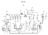
- FIG. 6C shows the process of gas exchange into the culture vessel 1 in Example 1.
- the solenoid valve closes the rubber tube and is in a closed state. Water is held in the humidification bottle 13, and the opening of one long tube is provided at the bottom of the vessel. One end of this is connected to the gas flow control unit 11 and the gas cylinder 10.
- the humidification bottle 13 also has a short tube opening at the top inside the vessel, with one end connected to the ventilation adapter.
- gas flow control unit 11 When the gas flow control unit 11 is operated, gas controlled at a predetermined air supply rate is sent into the humidification bottle, humidified, and sent out from the humidification bottle.
- the gas concentration in the gas space 8 of the ventilation adapter 7 then increases and is maintained at a predetermined gas concentration, so gas exchange to the culture vessel 1 continues (S04).
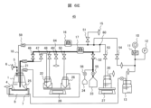
- FIG. 6D shows the process of adding culture medium to the culture vessel 1 in Example 1.
- the pump is stopped and the solenoid valve is closed by closing the rubber tube.
- Culture medium is held in the culture medium bottle 20, which is attached to the weight sensor 27.
- the solenoid valve 53 is opened, and the liquid supply tube 18 of the culture vessel 1 and the piping to the culture medium bottle 20 are opened.
- the pump 16 is operated, the culture medium passes through the piping and is sent to the culture vessel 1 via the liquid supply tube 18.
- the solenoid valve 51 is opened and the pump 16 is stopped at the same time.
- the flow of culture medium is temporarily stopped in the pipeline due to the stopping of the pump 16, and the culture medium in the pipeline close to the culture medium bottle 20 returns to the inside of the culture medium bottle 20 due to the difference in height as outside air enters through the vent filter that is open to the outside at the branching section 63.
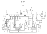
- FIG. 6E shows the process of discharging the culture medium during culture medium replacement in the culture vessel 1 in Example 1.
- the pump is stopped and the solenoid valve is closed by closing the rubber tube.
- Culture medium is held in the culture vessel 1, and the supernatant collection bag 23 is installed empty.
- solenoid valve 46, solenoid valve 52, and manual valve 55 are opened, and the suction tube 21 of the culture vessel 1 and the pipeline to the supernatant collection bag 23 are opened.
- pump 17 when pump 17 is operated, the culture medium is sent from the culture vessel 1 through the suction tube 21 and reaches the supernatant collection bag 23.
- solenoid valve 49 when solenoid valve 49 is opened, the medium in the pipeline closer to culture vessel 1 than branch 64 (same as branch 61 in Figure 6B) is sent to culture vessel 1 by the difference in height.
- solenoid valve 46 is closed and pump 17 is operated, outside air is introduced through the vent filter, and the medium in the pipeline reaches supernatant recovery bag 23. All solenoid valves are closed and the medium discharge process is completed (S06).
- medium replacement can be performed by similarly performing the process of adding medium to culture vessel 1 described using Figure 6D (S07).
- cell culture can be further promoted by rocking culture vessel 1 with rocking mechanism 30 to mix new medium with the cells.
- FIG. 6F shows the process of sampling the supernatant from the culture vessel 1 in Example 1.
- the pump is stopped and the solenoid valve is closed by closing the rubber tube.
- Culture medium is held in the culture vessel 1, and the supernatant analysis bag 24 is installed empty.
- solenoid valve 46, solenoid valve 52, and manual valve 56 are opened, and the suction tube 21 of the culture vessel 1 and the pipeline to the supernatant analysis bag 24 are opened.
- pump 17 when pump 17 is operated, the culture medium is sent from the culture vessel 1 through the suction tube 21 and reaches the supernatant analysis bag 24.
- solenoid valve 49 when solenoid valve 49 is opened, the medium in the pipeline closer to culture vessel 1 than branch 64 is sent to culture vessel 1 by the difference in height.
- solenoid valve 46 is closed and pump 17 is operated, outside air is introduced through the vent filter, and the medium in the pipeline reaches supernatant analysis bag 24. All solenoid valves are closed, and the supernatant sampling process is completed (S08).
- the cell recovery process from the culture vessel 1 in Example 1 will be explained with reference to Figures 6E and 6G. After the cells have sufficiently proliferated, they settle to the bottom of the culture vessel and float there. As in the supernatant recovery process in Figure 6E, the supernatant is recovered from the culture vessel 1 through the same flow path circuit, and supernatant recovery is continued until the culture medium 3 is below the height of the opening of the suction tube 21. This makes it possible to increase the ratio of culture medium 3 to cells in the culture vessel 1. Next, the culture vessel is rocked by the rocking mechanism 30 described above, and the culture medium and cells are stirred to produce a cell suspension.
- the rocking part 70 of the rocking mechanism 30 is tilted toward the side where the recovery pipe 25 is located, so that the cell suspension is collected on the wall side of the culture vessel 1 where the recovery pipe 25 is located.
- the tilt angle of the rocking part 70 should be greater than 0 degrees and less than 90 degrees as long as it can collect the cell suspension on the wall side of the culture vessel 1.
- the rocking part 70 must be able to tilt in a certain direction, and may be able to tilt in multiple directions.
- the solenoid valves 50 and 51 are opened, and the recovery pipe 25 of the culture vessel 1, the pipeline to the cell recovery bottle 26, and the pipeline to the CO 2 gas vent filter 15 open to the outside air are opened.
- the pump 17 when the pump 17 is operated, the cell suspension 65 is pumped from the culture vessel 1 through the recovery pipe 25 and reaches the cell recovery bottle 26 .
- solenoid valve 49 is opened and pump 17 is stopped at the same time. At this time, outside air enters through the vent filter that is open to the outside, and the inside of cell collection bottle 26 becomes normal pressure through branch 66, and the liquid transfer stops. All solenoid valves are closed and the cell collection process ends (S09).
- the waste bag is removed from the flow path (S10), and the flow path is removed from the automatic culture device (S11), completing all the steps of the automatic culture.
- the automated culture device is capable of culturing while miniaturizing the device. It is also possible to implement the device while reducing the risk of rust on mechanical elements such as the rocking mechanism for the culture vessel used in the culture operation and the camera observation mechanism for the cells. In addition, the risk of microbial growth throughout the entire incubator can be reduced by partially supplying humidified gas to the culture vessel using the ventilation adapter.
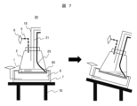
- FIG. 9 shows an example of a ventilation adapter for a flask culture vessel according to Example 2.
- the culture vessel 1 is a flask-type culture vessel, and is mainly used for cell culture with cells adhering to the bottom surface of the vessel.
- two screw ports 101 are provided on the ceiling surface of the main body, and each is closed by a ventilation cap 103 with a gas-permeable membrane 102 at the opening.
- the ventilation cap of one screw port is left as it is, and a method of gas exchange using a ventilation adapter 7 is shown, and a ported cap 104 with a liquid supply tube is installed on the other screw port, and automatic liquid supply is performed using an automatic culture device.
- the culture vessel 1 is installed on the rocking stage 31, and is connected to an air supply tube 42 connected to the humidification bottle 13 and an exhaust tube 43 connected to a CO2 sensor.
- One ventilation cap 103 in the culture vessel 1 is closely fitted with a ventilation adapter 7. At this time, a predetermined gas space 8 is created inside the ventilation cap 103 and the ventilation adapter 7.
- the ported cap 104 is provided with a liquid delivery tube 18, a suction tube 21, and a cell recovery tube 25, and these three ports are connected in the same manner as the automated culture device (Figure 1) and flow path circuit (Figure 6A) described in Example 1 above, and can perform the cell seeding process, gas exchange process, medium addition process, medium exchange process, supernatant sampling process, and cell recovery process described above.
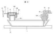
- FIG. 10 shows an example of an automatic culture system in which multiple automatic culture devices according to Example 1 are installed, connected to a network, and controlled by a central management PC.
- a stand is shown in which four sets of devices can be installed, two on each of the upper and lower levels, but the number of devices installed per level of the stand in this embodiment can be any number, making it easy to increase the number of devices that can be integrated in the limited space of the CPC equipment. From the perspective of accurate process management and aseptic operation, it is also possible to fully automate the installation and removal process of the flow paths by robots, and the number of devices that can be integrated can be increased beyond the reach of a human hand.
- Each control unit 38 is attached to the front of the door 37 of the incubator 35, and each is connected to the central control PC 106 via network equipment.
- the central control PC 106 has the function of monitoring the status of each piece of automatic culture equipment, the function of managing updates and modifications to the operating programs, and the function of transmitting information when an abnormality occurs in the equipment's operation or when operation has ended.
Landscapes
- Chemical & Material Sciences (AREA)
- Engineering & Computer Science (AREA)
- Health & Medical Sciences (AREA)
- Wood Science & Technology (AREA)
- Organic Chemistry (AREA)
- Life Sciences & Earth Sciences (AREA)
- Bioinformatics & Cheminformatics (AREA)
- Zoology (AREA)
- Biomedical Technology (AREA)
- Genetics & Genomics (AREA)
- Microbiology (AREA)
- Biotechnology (AREA)
- Biochemistry (AREA)
- General Engineering & Computer Science (AREA)
- General Health & Medical Sciences (AREA)
- Sustainable Development (AREA)
- Analytical Chemistry (AREA)
- Physics & Mathematics (AREA)
- Thermal Sciences (AREA)
- Clinical Laboratory Science (AREA)
- Computer Hardware Design (AREA)
- Apparatus Associated With Microorganisms And Enzymes (AREA)
Priority Applications (2)
| Application Number | Priority Date | Filing Date | Title |
|---|---|---|---|
| CN202380097789.4A CN121039268A (zh) | 2023-06-02 | 2023-12-20 | 自动培养装置、自动培养系统 |
| EP23939795.3A EP4722334A1 (en) | 2023-06-02 | 2023-12-20 | Automatic culture device and automatic culture system |
Applications Claiming Priority (2)
| Application Number | Priority Date | Filing Date | Title |
|---|---|---|---|
| JP2023-091700 | 2023-06-02 | ||
| JP2023091700A JP2024173345A (ja) | 2023-06-02 | 2023-06-02 | 自動培養装置、自動培養システム |
Publications (1)
| Publication Number | Publication Date |
|---|---|
| WO2024247328A1 true WO2024247328A1 (ja) | 2024-12-05 |
Family
ID=93657463
Family Applications (1)
| Application Number | Title | Priority Date | Filing Date |
|---|---|---|---|
| PCT/JP2023/045673 Ceased WO2024247328A1 (ja) | 2023-06-02 | 2023-12-20 | 自動培養装置、自動培養システム |
Country Status (4)
| Country | Link |
|---|---|
| EP (1) | EP4722334A1 (https=) |
| JP (1) | JP2024173345A (https=) |
| CN (1) | CN121039268A (https=) |
| WO (1) | WO2024247328A1 (https=) |
Cited By (1)
| Publication number | Priority date | Publication date | Assignee | Title |
|---|---|---|---|---|
| CN120249009A (zh) * | 2025-02-20 | 2025-07-04 | 河南中抗医学检验有限公司 | 一种医学检验微生物培养设备及培养方法 |
Citations (4)
| Publication number | Priority date | Publication date | Assignee | Title |
|---|---|---|---|---|
| JPH1189561A (ja) * | 1997-09-19 | 1999-04-06 | Kurea:Kk | 細胞培養方法および装置 |
| JP2006174828A (ja) * | 2004-11-29 | 2006-07-06 | Olympus Corp | 生体試料培養観察システム、インキュベータボックス、供給手段、および培養容器 |
| JP2007312668A (ja) | 2006-05-25 | 2007-12-06 | Hitachi Medical Corp | 自動培養装置 |
| WO2015059799A1 (ja) * | 2013-10-24 | 2015-04-30 | 株式会社日立製作所 | 自動培養装置 |
-
2023
- 2023-06-02 JP JP2023091700A patent/JP2024173345A/ja active Pending
- 2023-12-20 CN CN202380097789.4A patent/CN121039268A/zh active Pending
- 2023-12-20 EP EP23939795.3A patent/EP4722334A1/en active Pending
- 2023-12-20 WO PCT/JP2023/045673 patent/WO2024247328A1/ja not_active Ceased
Patent Citations (4)
| Publication number | Priority date | Publication date | Assignee | Title |
|---|---|---|---|---|
| JPH1189561A (ja) * | 1997-09-19 | 1999-04-06 | Kurea:Kk | 細胞培養方法および装置 |
| JP2006174828A (ja) * | 2004-11-29 | 2006-07-06 | Olympus Corp | 生体試料培養観察システム、インキュベータボックス、供給手段、および培養容器 |
| JP2007312668A (ja) | 2006-05-25 | 2007-12-06 | Hitachi Medical Corp | 自動培養装置 |
| WO2015059799A1 (ja) * | 2013-10-24 | 2015-04-30 | 株式会社日立製作所 | 自動培養装置 |
Non-Patent Citations (1)
| Title |
|---|
| See also references of EP4722334A1 |
Cited By (1)
| Publication number | Priority date | Publication date | Assignee | Title |
|---|---|---|---|---|
| CN120249009A (zh) * | 2025-02-20 | 2025-07-04 | 河南中抗医学检验有限公司 | 一种医学检验微生物培养设备及培养方法 |
Also Published As
| Publication number | Publication date |
|---|---|
| EP4722334A1 (en) | 2026-04-08 |
| JP2024173345A (ja) | 2024-12-12 |
| CN121039268A (zh) | 2025-11-28 |
Similar Documents
| Publication | Publication Date | Title |
|---|---|---|
| EP2832847B1 (en) | Culture vessel and automated culture apparatus | |
| US9175253B2 (en) | Cell culture shaking device and shaking culture method as cell culture method | |
| US20090042293A1 (en) | Cell Culture Apparatus, Cell Culture Method, Cell Culture Program and Cell Culture System | |
| JP4845950B2 (ja) | 自動培養装置 | |
| WO2024247328A1 (ja) | 自動培養装置、自動培養システム | |
| JP2016208866A (ja) | 自動培養装置 | |
| CN218521259U (zh) | 一种全自动全封闭细胞制备设备 | |
| US9212975B2 (en) | Collection unit | |
| CN107699483A (zh) | 一种医学检验微生物培养设备 | |
| JP4928831B2 (ja) | 自動培養装置 | |
| CN100497583C (zh) | 安全高效连续封闭式细胞培养病毒生产/灭活系统 | |
| TWI756886B (zh) | 細胞培養裝置 | |
| WO2025251645A1 (zh) | 一种无线便携式小型细胞培养箱 | |
| CN212357270U (zh) | 一种自动化ivf培养与时差分析装置及配套培养皿 | |
| CN106834117B (zh) | 用于解除动物细胞贴附的酶反应器及智能酶反应工作站 | |
| JP2025133331A (ja) | 自動培養装置、それを用いた細胞培養方法 | |
| JP7720162B2 (ja) | 細胞培養システム | |
| JP4274859B2 (ja) | 培養装置および自動培養装置 | |
| JP2026066996A (ja) | 自動培養装置 | |
| JP2025171355A (ja) | 自動培養装置、それを複数用いた自動培養システム | |
| RU2841776C1 (ru) | Биореактор для культивации клеток и получения вирусной суспензии и способ его работы | |
| JP2012005411A (ja) | 培養液供給装置及び培養装置 | |
| CN211367585U (zh) | 一种对接式二氧化碳培养系统 | |
| CN113267383B (zh) | 一种智能区分废液的全封闭式自动取样装置及其使用方法 | |
| RU2292387C2 (ru) | Установка для культивирования микроорганизмов |
Legal Events
| Date | Code | Title | Description |
|---|---|---|---|
| 121 | Ep: the epo has been informed by wipo that ep was designated in this application |
Ref document number: 23939795 Country of ref document: EP Kind code of ref document: A1 |
|
| WWE | Wipo information: entry into national phase |
Ref document number: 2023939795 Country of ref document: EP |
|
| NENP | Non-entry into the national phase |
Ref country code: DE |
|
| ENP | Entry into the national phase |
Ref document number: 2023939795 Country of ref document: EP Effective date: 20260102 |
|
| ENP | Entry into the national phase |
Ref document number: 2023939795 Country of ref document: EP Effective date: 20260102 |
|
| ENP | Entry into the national phase |
Ref document number: 2023939795 Country of ref document: EP Effective date: 20260102 |
|
| ENP | Entry into the national phase |
Ref document number: 2023939795 Country of ref document: EP Effective date: 20260102 |
|
| ENP | Entry into the national phase |
Ref document number: 2023939795 Country of ref document: EP Effective date: 20260102 |
|
| ENP | Entry into the national phase |
Ref document number: 2023939795 Country of ref document: EP Effective date: 20260102 |
|
| WWP | Wipo information: published in national office |
Ref document number: 2023939795 Country of ref document: EP |