WO2024246981A1 - 印刷システム及び印刷装置 - Google Patents
印刷システム及び印刷装置 Download PDFInfo
- Publication number
- WO2024246981A1 WO2024246981A1 PCT/JP2023/019690 JP2023019690W WO2024246981A1 WO 2024246981 A1 WO2024246981 A1 WO 2024246981A1 JP 2023019690 W JP2023019690 W JP 2023019690W WO 2024246981 A1 WO2024246981 A1 WO 2024246981A1
- Authority
- WO
- WIPO (PCT)
- Prior art keywords
- cutting
- unit
- printing
- cut
- line
- Prior art date
- Legal status (The legal status is an assumption and is not a legal conclusion. Google has not performed a legal analysis and makes no representation as to the accuracy of the status listed.)
- Ceased
Links
Images


Classifications
-
- B—PERFORMING OPERATIONS; TRANSPORTING
- B41—PRINTING; LINING MACHINES; TYPEWRITERS; STAMPS
- B41J—TYPEWRITERS; SELECTIVE PRINTING MECHANISMS, i.e. MECHANISMS PRINTING OTHERWISE THAN FROM A FORME; CORRECTION OF TYPOGRAPHICAL ERRORS
- B41J11/00—Devices or arrangements of selective printing mechanisms, e.g. ink-jet printers or thermal printers, for supporting or handling copy material in sheet or web form
- B41J11/66—Applications of cutting devices
- B41J11/70—Applications of cutting devices cutting perpendicular to the direction of paper feed
-
- B—PERFORMING OPERATIONS; TRANSPORTING
- B41—PRINTING; LINING MACHINES; TYPEWRITERS; STAMPS
- B41J—TYPEWRITERS; SELECTIVE PRINTING MECHANISMS, i.e. MECHANISMS PRINTING OTHERWISE THAN FROM A FORME; CORRECTION OF TYPOGRAPHICAL ERRORS
- B41J25/00—Actions or mechanisms not otherwise provided for
- B41J25/20—Auxiliary type mechanisms for printing distinguishing marks, e.g. for accenting, using dead or half-dead key arrangements, for printing marks in telegraph printers to indicate that machine is receiving
-
- B—PERFORMING OPERATIONS; TRANSPORTING
- B41—PRINTING; LINING MACHINES; TYPEWRITERS; STAMPS
- B41J—TYPEWRITERS; SELECTIVE PRINTING MECHANISMS, i.e. MECHANISMS PRINTING OTHERWISE THAN FROM A FORME; CORRECTION OF TYPOGRAPHICAL ERRORS
- B41J29/00—Details of, or accessories for, typewriters or selective printing mechanisms not otherwise provided for
- B41J29/38—Drives, motors, controls or automatic cut-off devices for the entire printing mechanism
Definitions
- This disclosure relates to a printing system and a printing device.
- Such a cutting printer has a function of cutting the print medium along a scanning direction that is perpendicular to the transport direction of the print medium.
- the printing system is a system having a printing device.
- the printing device includes a transport unit that transports the print medium along a transport direction, a printing unit that prints a cut line on the print medium, a cutting unit that cuts the print medium along a cutting direction that intersects with the transport direction, and a control unit that controls the printing unit to print the cut line along a direction different from the cutting direction.
- the printing device includes a transport unit that transports the print medium along a transport direction, a printing unit that prints a cut line on the print medium, a cutting unit that cuts the print medium along a cutting direction that intersects with the transport direction, and a control unit that controls the printing unit to print the cut line along a direction different from the cutting direction.
- FIG. 1 is a diagram illustrating an example of the configuration of a printing system according to a first embodiment.
- 1 is a diagram illustrating an example of the configuration of a printing apparatus according to a first embodiment.
- 1 is a perspective view showing a schematic external appearance example of a printing device according to a first embodiment.
- 1 is a cross-sectional view showing a schematic internal structure of a printing device according to a first embodiment.
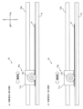
- FIG. 2 is a diagram illustrating a first configuration example of a cutting unit of the printing device according to the first embodiment.
- 6 is a diagram illustrating a second configuration example of the cutting unit of the printing device according to the first embodiment.
- FIG. FIG. 13 is a diagram illustrating a third example of the configuration of the cutting unit of the printing device according to the first embodiment.
- FIG. 13 is a diagram illustrating a fourth configuration example of the cutting unit of the printing device according to the first embodiment.
- 5A to 5C are diagrams illustrating a first example of printing cut lines and cutting paper according to the first embodiment.
- 10A to 10C are diagrams illustrating a second example of printing cut lines and cutting paper according to the first embodiment.
- 5A to 5C are diagrams for explaining a specific example of a paper cutting process according to the first embodiment.
- FIG. 2 is a diagram illustrating an example of the configuration of a terminal device according to the first embodiment.
- FIG. 4 is a diagram showing a first example of a preview display on a display unit of the terminal device according to the first embodiment.
- FIG. 11 is a diagram showing a second example of a preview display on the display unit of the terminal device according to the first embodiment.
- FIG. 4 is a diagram showing an example of an operation sequence of the printing system according to the first embodiment.
- FIG. 11 is a diagram showing a first operation pattern according to the second embodiment.
- 13A to 13C are diagrams for explaining a specific example of the first operation pattern of the second embodiment.
- 13A to 13C are diagrams for explaining a specific example of the first operation pattern of the second embodiment.
- 13A to 13C are diagrams for explaining a specific example of the first operation pattern of the second embodiment.
- FIG. 11 is a diagram showing a second operation pattern according to the second embodiment.
- 13A to 13C are diagrams for explaining a specific example of the second operation pattern of the second embodiment.
- 13A to 13C are diagrams for explaining specific examples of other operation patterns according to the second embodiment.
- FIG. 13 is a diagram illustrating a configuration of a printing device according to another embodiment.
- Cutting printers may want to implement various cutting methods, such as cutting paper as a print medium into a grid pattern or cutting out pieces of paper that are not rectangular in shape.
- a printing system and printing device are provided that can accommodate a variety of cutting methods while suppressing increases in costs.
- the printing system is a printing system having a printing device.
- the printing device includes a transport unit that transports the print medium along a transport direction, a printing unit that prints a cut line on the print medium, a cutting unit that cuts the print medium along a cutting direction that intersects with the transport direction, and a control unit that controls the printing unit to print the cut line in a direction different from the cutting direction.
- the cutting unit cuts the print medium along a cutting direction that intersects with the transport direction, and the printing unit can print cut lines on the print medium along a direction different from the cutting direction, so that cut lines that the cutting unit cannot handle can be substituted with printed cut lines.
- the user simply cuts with scissors or a cutter along the cut lines printed on the print medium after cutting by the cutting unit.
- the printing unit is a mechanism that is inherent to the printing device, and by having the printing unit print cut lines, the mechanism to be added to the cutting printer can be minimized, thereby suppressing increases in costs.
- the printing system according to the embodiment can be made compatible with various cutting methods while suppressing increases in costs.
- the print medium may be any medium on which printing can be performed and is not limited to paper media.
- the print medium may also be a resin medium such as an overhead projector (OHP) sheet.
- OHP overhead projector
- drawings are schematic and the ratios of the dimensions may differ from the actual ones. Therefore, the specific dimensions should be determined with reference to the explanation below. Furthermore, the drawings may contain parts where the dimensional relationships or ratios differ from one another.
- the printing system according to this embodiment has a printing device (also called a “printer”) 1 and a terminal device 2.
- the printing device 1 is a cutting printer that has a printing function for printing on paper, as well as a cutting function for cutting paper.
- the printing device 1 may be an MFP (Multi-Function Peripheral) that has a scanning function and/or a facsimile function in addition to the printing and cutting functions.
- the printing device 1 also has a communication function for communicating with the terminal device 2.
- the terminal device 2 is a mobile terminal or a stationary terminal.
- the mobile terminal may be, for example, a smartphone, a tablet terminal, or a notebook computer (PC).
- the terminal device 2 may be, for example, a desktop PC.
- the terminal device 2 may be an operation terminal used exclusively for operating the printing device 1. Such an operation terminal may constitute a part of the printing device 1.
- the terminal device 2 has a communication function for communicating with the printing device 1.
- the printing device 1 has a printing unit 3, a conveying unit 6, a cutting unit 10, a scanner unit 15, a communication unit 110, an operation panel 130, a control unit 150, and a storage unit 170.
- the printing unit 3 prints on paper under the control of the control unit 150. Specifically, the printing unit 3 prints on paper set in the printing device 1 and ejects the paper after printing.
- the printing device 1 may have only one paper feed tray, or may have multiple paper feed trays. From another perspective, the printing device 1 may have a function for selecting the size of paper.
- the printing unit 3 may be configured to be capable of color (as well as monochrome and grayscale) printing, or may be configured to be capable of only grayscale (and monochrome) printing, or may be configured to be capable of only monochrome printing.
- the printing unit 3 may be an inkjet printer that prints by ejecting ink, a thermal printer that prints by heating thermal paper or an ink ribbon, or an electrophotographic printer (e.g., a laser printer) that transfers toner attached to a photoconductor irradiated with light.
- the printing unit 3 may be a line printer whose head has a length spanning the width of the paper (a direction intersecting the paper transport direction), or a serial printer whose head moves in the width direction of the paper.
- the printing method is an inkjet method.
- the transport unit 6 transports the paper in the transport direction under the control of the control unit 150.
- the transport unit 6 includes, for example, one or more rollers (feed roller, transport roller) and one or more motors (feed motor, transport motor) that rotate the rollers.
- the cutting unit 10 cuts the paper along a cutting direction that intersects with the transport direction. Specifically, the cutting unit 10 cuts the paper after printing by the printing unit 3, and ejects the cut paper.
- the scanner unit 15 scans paper (original) on which an image is printed.
- the scanner unit 15 scans an original placed on a platen or ADF (Auto Document Feeder) using an imaging device that moves along the original glass, and generates image data.
- ADF Auto Document Feeder
- the communication unit 110 communicates with the terminal device 2 under the control of the control unit 150.
- the communication between the printing device 1 and the terminal device 2 may be wireless communication or wired communication.
- the wireless communication may be indirect wireless communication via an access point, or direct wireless communication without an access point.
- the indirect wireless communication may be, for example, an infrastructure mode of a wireless LAN (Local Area Network) communication method.
- the direct wireless communication may be an ad-hoc mode of a wireless LAN communication method or a Bluetooth wireless communication method.
- the wired communication may be, for example, a wired LAN communication or a USB (Universal Serial Bus) communication.
- the communication unit 110 may be regarded as a component that includes only hardware components (for example, a connector, an antenna, an amplifier, a filter, and an RF (Radio Frequency) circuit), or may be regarded as a component that includes software components in addition to hardware components.
- hardware components for example, a connector, an antenna, an amplifier, a filter, and an RF (Radio Frequency) circuit
- RF Radio Frequency
- the operation panel 130 includes a display unit 131 and an operation unit 132.
- the display unit 131 is configured with a liquid crystal display unit or an organic EL (Electro Luminescence) display unit.
- the display unit 131 has a relatively large number of pixels arranged regularly, and displays an image including any shape based on image data under the control of the control unit 150.
- the display unit 131 may be capable of displaying color images, may be capable of displaying only grayscale images (and monochrome images), or may be capable of displaying only monochrome images (binary images).
- the printing device 1 does not necessarily have to have the display unit 131. In that case, it may be assumed that the terminal device 2 performs operations on the printing device 1.
- the operation unit 132 includes one or more physical buttons (physical keys) and/or a touch panel in the touch panel display unit.
- the touch panel may be of an electrostatic type or a pressure-sensitive type.
- the touch panel overlaying the display unit 131 detects the position of a touch operation on the display unit 131 and outputs the detection result.
- the operation unit 132 includes a power on/off button (physical key) used to turn the power of the printing device 1 on/off.
- the control unit 150 is configured to include one or more processors, and controls the entire printing device 1.
- the control unit 150 may include a logic circuit or the like configured to perform only certain operations.
- the control unit 150 executes various processes and various controls by executing a program stored in the memory unit 170.
- the operations of the printing device 1 described above and below may be operations controlled by the control unit 150.
- the control unit 150 executes a print job in response to the communication unit 110 receiving from the terminal device 2 a print job including print target data, which is image data of the print target. Specifically, the control unit 150 controls the printing unit 3 (and the transport unit 6) to print an image based on the image data on paper. Alternatively, the control unit 150 may control the printing unit 3 to print an image based on image data stored in a storage medium such as a USB memory connected to the printing device 1.
- the control unit 150 may obtain setting information regarding printing of a cut line on the paper and cutting of the paper based on a user operation on the operation panel 130 or communication of the communication unit 110. The setting information may be included in the print job (print target data).
- the control unit 150 controls the printing unit 3 (and the transport unit 6) to print a cut line on the paper based on the setting information.
- the control unit 150 also controls the cutting unit 10 (and the transport unit 6) to cut the paper based on the setting information.
- the control unit 150 also executes a copy job in response to the operation panel 130 accepting a user operation to copy an original, or in response to the communication unit 110 receiving a copy command from the terminal device 2. Specifically, the control unit 150 controls the scanner unit 15 to scan an original set in the printing device 1, and then controls the printing unit 3 to print an image based on image data obtained by scanning on paper. Here, the control unit 150 may acquire setting information based on a user operation on the operation panel 130 or communication of the communication unit 110. The control unit 150 controls the printing unit 3 (and the conveying unit 6) to print a cut line on the paper based on the setting information. The control unit 150 controls the cutting unit 10 (and the conveying unit 6) to cut the paper based on the setting information.
- a new job for cutting and printing paper (also called “cut and print”) may be defined.
- the control unit 150 executes cut and print in response to the operation panel 130 accepting a user operation to cut paper, or the communication unit 110 receiving a cutting command from the terminal device 2.
- the control unit 150 may acquire setting information based on the user operation on the operation panel 130 or the communication of the communication unit 110.
- the control unit 150 controls the printing unit 3 (and the conveying unit 6) to print a cut line on the paper based on the setting information.
- the control unit 150 controls the cutting unit 10 (and the conveying unit 6) to cut the paper based on the setting information.
- control unit 150 executes scanning in response to the operation panel 130 accepting a user operation to scan an original document, or in response to the communication unit 110 receiving a scan command from the terminal device 2. Specifically, the control unit 150 controls the scanner unit 15 to scan an original document set in the printing device 1, and controls the communication unit 110 to store the image data obtained by scanning in the auxiliary storage device (non-volatile memory from another perspective) of the storage unit 170, or to transmit the image data obtained by scanning to the terminal device 2.
- auxiliary storage device non-volatile memory from another perspective
- the storage unit 170 is configured to include various memories, such as, for example, a ROM (Read Only Memory), a RAM (Random Access Memory), and an auxiliary storage device.
- ROM Read Only Memory
- RAM Random Access Memory
- the combination of the control unit 150 and the storage unit 170 may be considered as a computer.
- the programs executed by the control unit 150 are stored, for example, in the ROM of the storage unit 170 and/or the auxiliary storage device.
- the various components of the printing device 1 are electrically connected by a bus 190.
- all components are connected to a single bus 190, but multiple buses, such as an address bus, a data bus, and a control bus, may be provided.
- An interface may also be provided between the bus 190 and each component.
- FIG. 2 is merely a schematic diagram.
- the control unit 150 and memory unit 170 may be provided in a distributed manner in multiple locations.
- each unit may have a processor included therein (a control unit that controls each unit from another perspective) and a higher-level processor (a higher-level control unit that controls the control unit of each unit).
- the control unit 150 may be regarded as a higher-level control unit, or as a combination of the control unit of each unit and the higher-level control unit.
- the printing device 1 configured in this manner includes a conveying unit 6 that conveys the paper along the conveying direction, a printing unit 3 that prints a cut line on the paper, a cutting unit 10 that cuts the paper along a cutting direction that intersects with the conveying direction, and a control unit 150 that controls the printing unit 3 to print the cut line along a direction different from the cutting direction. Since the cutting unit 10 cuts the paper along the cutting direction that intersects with the conveying direction and the printing unit 3 can print the cut line on the paper along a direction different from the cutting direction, it is possible to substitute the printed cut line for a cut line that cannot be handled by the cutting unit 10. The user can cut the paper with scissors or a cutter along the cut line printed on the paper after cutting by the cutting unit 10.
- the printing unit 3 is a mechanism that the printing device 1 originally has, and since the printing unit 3 prints the cut line, additional mechanisms can be minimized, and an increase in costs can be suppressed. Therefore, according to the printing device 1 according to this embodiment, it is possible to handle various cutting methods while suppressing an increase in costs.
- Example of the structure of the printing device Fig. 3 is a perspective view showing an example of the schematic appearance of the printing device 1 according to this embodiment.
- the printing device 1 is a small type that is mainly installed in homes.
- the printing device 1 may also be a large type that is installed in an office or store.
- the up-down direction, left-right direction (also referred to as the "width direction"), and front-rear direction of the printing device 1 are defined based on the position of the printing device 1 installed on a horizontal surface so that it can be used.
- the front of the printing device 1 is the discharge direction of the paper P
- the rear of the printing device 1 is the opposite direction to the discharge direction of the paper P.
- the front of the printing device 1 may be the direction in which the operation panel 130, where the user can perform various settings, is located.
- the printing device 1 is an MFP having a printing unit 3 and a scanner unit 15.
- the printing unit 3 has an inkjet printing function that records print target data, which is image data specified by a print job, on paper P by ejecting ink, which is an example of a liquid.
- the scanner unit 15 is rotatably provided above the printing unit 3 in the printing device 1, and has a scanner function that reads the image recorded on paper P.
- An opening 20 is formed on the front of the printing device 1.
- a feed tray 21 and a discharge tray 22 are arranged in the opening 20 so that they can move forward and backward.
- the feed tray 21 is a case for storing multiple sheets of paper P.
- the discharge tray 22 is arranged above the feed tray 21, and supports the sheets of paper P on which an image has been printed.
- the size of the sheets of paper P is, for example, A4 size.
- the front of the printing device 1 is provided with an operation panel 130 having a display unit 131.
- the operation panel 130 includes, for example, a touch panel, and is configured to allow the user to perform touch operations to configure various settings related to printing by the printing device 1, etc.
- the configured information is output to the control unit 150.
- FIG. 4 is a cross-sectional view showing the schematic internal structure of the printing device 1 according to this embodiment.
- a feed roller 23 Inside the printing device 1, there are arranged a feed roller 23, a transport path R, transport rollers 60, 62, 64, and 66, a printing unit 3, and a cutting unit 10.
- the feed roller 23 and the transport rollers 60, 62, 64, and 66 are an example of a transport unit 6 that transports the paper P in the transport direction D1.
- the feed roller 23 is a roller for feeding the paper P stored in the feed tray 21 to the transport path R.
- the feed roller 23 is rotatably supported at the tip of a feed arm (not shown).
- the feed arm is biased to rotate toward the feed tray 21 by its own weight or the elastic force of a spring or the like.
- the feed roller 23 rotates when a feed motor (not shown) is driven. As the feed roller 23 rotates, the paper P stored in the feed tray 21 is sent one sheet at a time to the transport path R.
- the paper P fed to the transport path R is transported in the transport direction D1, i.e., from the rear to the front of the printing device 1.
- the transport path R refers to the space formed by the guide members 41, 42, 43 and the printing unit 3, etc.
- the transport path R extends upward from the rear end of the feed tray 21, curves in the area defined by the guide members 41, 42, passes through the position of the printing unit 3, extends in a straight line in the area defined by the guide member 43, and is a path that reaches the discharge tray 22.
- a transport roller 60 is disposed upstream of the printing unit 3 in the transport path R in the transport direction D1.
- a pinch roller 61 is disposed opposite the lower part of the transport roller 60.
- the transport roller 60 is driven by a transport motor (not shown).
- the pinch roller 61 rotates in conjunction with the rotation of the transport roller 60. As the transport roller 60 and pinch roller 61 rotate, the paper P is clamped between the transport roller 60 and pinch roller 61 and transported to the printing unit 3.
- the printing unit 3 includes a head carriage 31, a print head 32, an ink cartridge 33, a platen 34, and a drive mechanism for the head carriage 31, and is used to print an image on paper P.
- the printing unit 3 is disposed between a transport roller 60 and a transport roller 62 on the transport path R.
- the print head 32 is mounted on the head carriage 31.
- the bottom surface of the print head 32 is a nozzle surface on which multiple nozzles are formed.
- the print head 32 ejects ink from the nozzles onto the paper P by vibrating a vibration element such as a piezoelectric element.
- a vibration element such as a piezoelectric element.
- the nozzles eject ink of three colors, yellow, cyan, and magenta, as well as black ink.
- the platen 34 is a rectangular plate-shaped member on which the paper P is placed. As the head carriage 31 moves relative to the paper P supported by the platen 34, the print head 32 selectively ejects ink droplets, thereby printing an image on the paper P.
- the head carriage 31 is attached to the two guide rails 35, 36.
- the head carriage 31 is configured to be able to move left-right along the two guide rails 35, 36 in the area facing the platen 34.
- a drive belt (not shown) is also attached to the head carriage 31.
- the drive belt is an endless belt, and is connected to a head carriage motor (not shown). The head carriage 31 moves back and forth left-right when the head carriage motor is driven in the forward or reverse direction.
- the control unit 150 moves the head carriage 31 in the scanning direction while the transport of the paper P is stopped, and repeats a process of ejecting ink from the print head 32 to print one line of an image on the paper P, and a line feed process of driving the transport rollers 60 and 62 to transport the paper P by a specified line feed amount. In this way, the desired image, etc. is printed on the paper P.
- a transport roller 62 is disposed downstream of the printing unit 3 on the transport path R in the transport direction D1.
- a spur roller 63 is disposed opposite the top of the transport roller 62.
- the transport roller 62 is driven by a transport motor (not shown).
- the spur roller 63 rotates in conjunction with the rotation of the transport roller 62. As the transport roller 62 and spur roller 63 rotate, the paper P is clamped between the transport roller 62 and spur roller 63 and transported downstream in the transport direction D1.
- a transport roller 64 is disposed downstream of the transport roller 62 in the transport direction D1 on the transport path R.
- a spur roller 65 is disposed in a position facing the upper part of the transport roller 64.
- the transport roller 64 is driven by a transport motor (not shown).
- the spur roller 65 rotates in conjunction with the rotation of the transport roller 64.
- the paper P is clamped between the transport roller 64 and the spur roller 65 and transported to the cutting unit 10.
- An example of the configuration of the cutting unit 10 will be described later.
- a transport roller 66 is disposed downstream of the cutting section 10 in the transport path R in the transport direction D1.
- a spur roller 67 is disposed opposite the top of the transport roller 66.
- the transport roller 66 is driven by a transport motor (not shown).
- the spur roller 67 rotates in conjunction with the rotation of the transport roller 66. As the transport roller 66 and the spur roller 67 rotate, the paper P is transported to the transport roller 66 and discharged to the discharge tray 22.
- FIG. 5 is a diagram showing a first configuration example of the cutting unit 10 of the printing device 1 according to this embodiment. As described above, the cutting unit 10 is disposed between the transport roller 64 and the transport roller 66 on the transport path R.
- the cutting section 10 includes cutter units 10a and 10b.
- the upper cutter carriage 11a moves in the scanning direction (horizontal movement) due to the driving force of a cutter carriage motor (not shown).
- the cutter carriage 11a is also configured to be drivable in the vertical direction (vertical movement).
- the lower cutter carriage 11b moves in the scanning direction together with the upper cutter carriage 11a due to the driving force of a cutter carriage motor (not shown) (horizontal movement).
- a circular upper blade 12a is rotatably attached to the upper cutter carriage 11a, for example by a screw.
- a circular lower blade 12b is rotatably attached to the lower cutter carriage 11b, for example by a screw.
- the cutting unit 10 cuts the paper P by rotating the upper blade 12a and the lower blade 12b and bringing them into contact with each other.
- the upper blade 12a and the lower blade 12b may be fixed blades, or a combination of a rotating blade and a fixed blade. Also, only one of the upper blade 12a and the lower blade 12b may be used.
- the cutting unit 10 is supported by support rails 13a and 13b extending in the scanning direction so that it can move in the scanning direction.
- An endless belt wound around a rotating shaft (not shown) is provided on the support rails 13a and 13b.
- the endless belt is connected to the upper cutter carriage 11a and the lower cutter carriage 11b.
- the rotating shaft is rotated by the driving force of the cutter carriage motor, causing the endless belt to rotate, and the upper cutter carriage 11a and the lower cutter carriage 11b move in the scanning direction along the support rails 13a and 13b.
- the cutter unit 10a is configured to be vertically movable. Therefore, it is possible to handle not only the first cutting process, which completely cuts the paper P in the scanning direction (cutting direction), but also the second cutting process, which partially cuts the paper P in the scanning direction.
- FIG. 6 is a diagram showing a second configuration example of the cutting unit 10 of the printing device 1 according to this embodiment.
- differences from the first configuration example described above will be mainly explained.
- the cutting section 10 includes a cutter unit 10a and a lower rail 14.
- the cutter unit 10a is configured in the same manner as the first configuration example described above.
- the lower rail 14 has a concave cross-sectional shape and forms a groove extending in the scanning direction.
- the cutter unit 10a is supported by a support rail 13a extending in the scanning direction so that it can move in the scanning direction.
- the support rail 13a is provided with an endless belt wound around a rotating shaft (not shown).
- the endless belt is connected to the upper cutter carriage 11a.
- the rotating shaft is rotated by the driving force of the cutter carriage motor, causing the endless belt to rotate, and the upper cutter carriage 11a moves in the scanning direction along the support rail 13a.
- the cutting section 10 cuts the paper P by rotating the upper blade 12a along the groove of the lower rail 14 and bringing it into contact with the paper P.
- the cutter unit 10a is configured to be vertically movable, as in the first configuration example described above. Therefore, it is possible to handle not only the first cutting process, which completely cuts the paper P in the scanning direction (cutting direction), but also the second cutting process, which partially cuts the paper P in the scanning direction.
- FIG. 7 is a diagram showing a third configuration example of the cutting unit 10 of the printing device 1 according to this embodiment.
- differences from the first and second configuration examples described above will be mainly explained.
- the cutting section 10 includes a cutter unit 10a, a perforation cutter unit 10c, and a lower rail 14.
- the cutter unit 10a and the lower rail 14 are configured in the same manner as in the first configuration example described above.
- the perforation cutter unit 10c is supported by the support rail 13a so as to be movable independently of the cutter unit 10a.
- the perforation cutter unit 10c may be supported by a support rail other than the support rail 13a so as to be movable.
- the cutter carriage 11c moves in the scanning direction (horizontal movement) by the driving force of a cutter carriage motor (not shown).
- the cutter carriage 11c may also be configured to be drivable in the vertical direction (vertical movement).
- a perforation cutter blade 12c having a wavy cutting edge around its entire circumference is rotatably attached to the cutter carriage 11c, for example by a screw or the like.
- the support rail 13a is provided with an endless belt wound around a rotating shaft (not shown).
- the endless belt is connected to the cutter carriage 11c.
- the driving force of the cutter carriage motor rotates the rotating shaft and rotates the endless belt, causing the cutter carriage 11c to move in the scanning direction along the support rail 13a.
- the cutting unit 10 cuts the paper P to form perforations by rotating the perforation cutter blade 12c along the groove of the lower rail 14 and bringing it into contact with the paper P.
- cutter unit 10a moves in the scanning direction along support rail 13a while perforation cutter unit 10c waits at the left end of support rail 13a without moving.
- perforation cutter unit 10c moves in the scanning direction along support rail 13a while cutter unit 10a waits at the right end of support rail 13a without moving.
- the cutting unit 10 includes two types of cutters: a cutter unit 10a, which is a cutting cutter used in a first cutting process that completely cuts the paper P in the cutting direction, and a perforation cutter unit 10c, which is a perforation cutter used in a second cutting process that partially cuts the paper P in the cutting direction.
- a cutter unit 10a which is a cutting cutter used in a first cutting process that completely cuts the paper P in the cutting direction
- a perforation cutter unit 10c which is a perforation cutter used in a second cutting process that partially cuts the paper P in the cutting direction.
- FIG. 8 is a diagram showing a fourth configuration example of the cutting unit 10 of the printing device 1 according to this embodiment.
- differences from the first to third configuration examples described above will be mainly explained.
- the cutting section 10 differs from the third configuration example described above in that it does not have a cutter unit 10a, but the other configurations are the same as those of the third configuration example described above.
- the perforation cutter unit 10c is configured to be able to move vertically, so the cutting depth of the perforation cutter blade 12c on the paper P can be variably set.
- FIG. 9 is a diagram showing a first example of printing perforation lines and cutting paper P according to this embodiment.
- the printing unit 3 of the printing device 1 prints cut lines on the paper P along the transport direction (the vertical direction of the paper P).
- the cut lines are generally dashed lines, but may be solid lines (continuous lines), dashed lines, or dashed lines, etc. At least one of the type, color, and thickness of the cut lines may be configurable in the printing device 1 according to user operation. In the illustrated example, multiple vertical cut lines (dashed lines) are printed at predetermined intervals across the paper P.
- the cutting section 10 of the printing device 1 cuts the paper P in a direction perpendicular to the transport direction (the horizontal direction of the paper P).
- a complete cut is shown as an example of cutting the paper P, and the paper P is cut horizontally multiple times at predetermined intervals in the vertical direction of the paper P.
- the printing device 1 discharges the cut paper P as shown in Figure 9(b) onto the discharge tray 22.
- the user cuts the cut sheets of paper P along the cut lines printed on each sheet with scissors or a cutter.
- control unit 150 of the printing device 1 controls the printing unit 3 to print multiple cut lines on the paper P along a direction perpendicular to the cutting direction (scanning direction), and controls the cutting unit 10 to cut the paper P multiple times along the cutting direction (scanning direction). This makes it easy to create multiple small cards from the paper P.
- the printing unit 3 printing multiple cut lines at equal intervals on the paper P and the cutting unit 10 cutting the paper P at equal intervals, it is easy to create multiple cards of the same size from the paper P.
- FIG. 10 is a diagram showing a second example of printing cut lines and cutting paper P according to this embodiment.
- the cutting unit 10 of the printing device 1 cuts the paper P in the horizontal direction at the center position of the paper P in the vertical direction.
- the printing unit 3 of the printing device 1 prints a cut line on the paper P along the vertical direction of the paper P at the center position of the horizontal direction of the paper P.
- the cutting unit 10 of the printing device 1 also cuts the paper P along the horizontal direction of the paper P at the center position of the vertical direction of the paper P.
- the printing unit 3 of the printing device 1 prints cut lines on the paper P along the vertical direction of the paper P at the center of the horizontal direction of the paper P.
- the cutting unit 10 of the printing device 1 also cuts the paper P twice along the horizontal direction of the paper P at equal intervals in the vertical direction of the paper P.
- the printing unit 3 of the printing device 1 prints cut lines on the paper P along the vertical direction of the paper P at the center of the horizontal direction of the paper P.
- the cutting unit 10 of the printing device 1 also cuts the paper P three times along the horizontal direction of the paper P at equal intervals along the vertical direction of the paper P.
- the printing unit 3 of the printing device 1 prints two cut lines on the paper P along the vertical direction of the paper P at equal intervals in the horizontal direction of the paper P.
- the cutting unit 10 of the printing device 1 also cuts the paper P three times along the horizontal direction of the paper P at equal intervals in the vertical direction of the paper P.
- the printing unit 3 of the printing device 1 prints three cut lines on the paper P along the vertical direction of the paper P at equal intervals in the horizontal direction of the paper P.
- the cutting unit 10 of the printing device 1 also cuts the paper P three times along the horizontal direction of the paper P at equal intervals in the vertical direction of the paper P.
- Each of the division methods shown in FIG. 10(a) to FIG. 10(a) may be preset in the printing device 1.
- One of these division methods may be selected in response to a user operation, and the printing device 1 may print a cut line on the paper P and cut the paper P according to the selected division method.
- FIG. 11 is a diagram for explaining a specific example of the cutting process of the paper P according to this embodiment.
- the control unit 150 of the printing device 1 selects at least one of a first cutting process, which completely cuts the paper P in the cutting direction, and a second cutting process, which partially cuts the paper P in the cutting direction, and causes the cutting unit 10 to execute the selected cutting process.
- the cutting direction is the scanning direction and the lateral direction of the paper P.
- FIG. 11(a) An example of the first cutting process (also called the "complete cutting process") is shown in FIG. 11(a).
- FIG. 11(a) shows an example of dividing the paper P into two pieces by completely cutting it.
- the cutting unit 10 of the printing device 1 cuts the paper P in the horizontal direction at the center position of the paper P in the vertical direction.
- FIG. 11(b) shows an example of forming perforations in the paper P as partial cutting of the paper P.
- the cutting unit 10 of the printing device 1 forms perforations in the paper P along the horizontal direction of the paper P at the center position in the vertical direction of the paper P.
- Fig. 11(c) shows an example of partial cutting of the paper P with both ends left. When both ends are left, the cutting unit 10 of the printing device 1 cuts the central part of the paper P along the cutting direction without cutting both ends of the paper P along the cutting direction. When both ends are left, the length of the central part of the paper P to be cut may be variably set according to a user operation.
- the paper P discharged from the printing device 1 remains at its original size.
- the user can easily cut the paper P along the perforations themselves at any time.
- the user can easily cut both uncut end portions of the paper P themselves at any time. It is also possible for the printing unit 3 to print an image on the front side of the paper P, and then the cutting unit 10 to perform partial cutting, and then the printing unit 3 to print an image on the back side of the paper P.
- FIG. 12 is a diagram showing an example of the configuration of the terminal device 2 according to this embodiment.
- the terminal device 2 has a communication unit 210, a display unit 221, an operation unit 222, an imaging unit 230, a control unit 240, and a storage unit 250.
- the terminal device 2 does not necessarily have to have the imaging unit 230.
- the communication unit 210 communicates with the printing device 1 under the control of the control unit 240. Furthermore, the communication unit 210 may be connected to a network and communicate with an external server via the network.
- the display unit 221 displays an image under the control of the control unit 240.
- the operation unit 222 accepts user operations (user input).
- the display unit 221 is configured with a liquid crystal display unit or an organic EL display unit.
- At least a part of the operation unit 222 may be integrated with the display unit 221 to configure the touch panel display unit 220. In that case, the operation unit 222 detects the position of a touch operation on the display unit 221 and outputs the detection result.
- at least a part of the operation unit 222 may be configured as one or more physical buttons.
- the operation unit 222 may be configured to include a keyboard, a mouse, and/or a touchpad, etc.
- the imaging unit 230 constitutes a camera including an image sensor such as a CCD (Charge Coupled Device) or a CMOS (Complementary Metal Oxide Semiconductor).
- the imaging unit 204 electronically captures an image under the control of the control unit 240 and outputs image data.
- the control unit 240 is configured to include one or more processors, and controls the entire terminal device 2.
- the control unit 240 may include a logic circuit or the like configured to perform only certain operations. The operations of the terminal device 2 described above and below may be operations controlled by the control unit 240.
- the storage unit 250 is configured to include various memories, such as, for example, a ROM, a RAM, and an auxiliary storage device.
- the combination of the control unit 240 and the storage unit 250 may be considered as a computer.
- the programs executed by the control unit 240 are stored, for example, in the ROM and/or the auxiliary storage device of the storage unit 250.
- the components of the terminal device 2 are electrically connected by a bus 260.
- a bus 260 In the illustrated example, all components are connected to a single bus 260, but multiple buses, for example, an address bus, a data bus, and a control bus, may be provided.
- An interface may also be provided between the bus 260 and each component.
- control unit 240 executes the programs stored in the storage unit 250 to perform the functions of the acquisition unit 241, image data processing unit 242, and display processing unit 243.
- the acquisition unit 241 acquires print target data, which is image data to be printed by the printing device 1.
- the print target data may be graphic drawing data (illustration data), photo data, or text data.
- the acquisition unit 241 may acquire print target data stored in the storage unit 250 of the terminal device 2, may acquire print target data (e.g., scanned data) from the printing device 1 via the communication unit 210, or may acquire print target data from an external server via the communication unit 210.
- the image data processing unit 242 performs processing based on the data to be printed, and generates setting information related to printing a cut line on the paper P and cutting the paper P.
- the image data processing unit 242 generates setting information in response to a user operation received from the user by the operation unit 222 during preview display.
- the image data processing unit 242 transmits a print job (or a cut print job) including the generated setting information to the printing device 1 via the communication unit 210.
- the setting information related to printing a cut line on the paper P may be combined with the data to be printed by image processing including drawing the cut line.
- the display processing unit 243 performs processing to display a preview screen including a preview image of the paper P. Specifically, the display processing unit 243 causes the display unit 221 to display the preview screen. The display processing unit 243 may also cause the display unit 221 to display a preview screen corresponding to the data to be printed acquired by the acquisition unit 241. In other words, the display processing unit 243 may cause the display unit 221 to display a preview screen including a preview image (also referred to as a "print preview") of when an image based on the data to be printed acquired by the acquisition unit 241 is printed on the paper P.
- a preview image also referred to as a "print preview
- the display processing unit 243 displays, on the preview screen, the cut line along which the paper P will be cut by the cutting unit 10 and the cut line to be printed on the paper P, superimposed on the print preview (preview image of the paper P). This allows the user to understand, based on the preview screen, how the paper P will be cut, and what kind of cut line will be printed on the paper P.
- the image data processing unit 242 generates setting information indicating the selected cut line mode based on a user operation to set on the preview screen the mode of the cut line when cutting the paper P by the cutting unit 10.
- the cut line mode includes at least one of the cut line position indicating the position of the cut line, the cut line number indicating the number of cut lines, and the cut line type indicating whether the cut line is a complete cut or a partial cut. Partial cuts may be subdivided into "perforation,” “leaving both ends,” and "any partial cut.”
- the control unit 150 controls the cutting unit 10 based on the setting information to cut the paper P along the cut line of the mode selected by the user operation. This allows the user to arbitrarily set the mode of the cut line, making it possible to accommodate a variety of cutting methods.
- the image data processing unit 242 also generates setting information indicating the selected cut line mode based on a user operation to set on the preview screen the mode of the cut line to be printed on the paper P.
- the cut line mode includes at least one of the following: line type indicating the type of cut line, line color indicating the color of the cut line, and line thickness indicating the thickness of the cut line.
- the control unit 150 controls the printing unit 3 to print the cut line in the mode selected by the user operation based on the setting information. This allows the user to arbitrarily set the cut line mode, making it possible to accommodate a variety of cutting methods and print appropriate cut lines.
- the display processing unit 243 may perform at least one of a first display process that displays a preview image of the paper P at actual size on the preview screen, and a second display process that displays a scale together with the preview image of the paper P. This allows the user to easily grasp the actual size of each area to be cut from the preview display.
- FIG. 13 is a diagram showing a first example of a preview display on the display unit 221 of the terminal device 2 according to this embodiment.
- the preview screen is divided into a preview area and a settings area.
- the preview area displays a preview image (print preview) of the image based on the data to be printed (in the illustrated example, an illustration of a flower) when printed on paper P.
- the settings area displays multiple objects (buttons) for accepting user operations regarding various settings.
- the settings area includes a "Paper Settings” button for selecting the type of paper P, a “Actual Size Display” button for displaying the print preview at actual size, and a “Cut and Print” area for setting cut and print.
- the "Paper Settings” button is selected, the screen transitions to a screen for selecting at least one of the paper size, paper type, and paper color, or an object is displayed as a pop-up.
- the "Actual Size Display” button is selected, a preview image of the paper P is displayed at actual size in the preview area.
- the "Cut Print” area includes a "Preset Division” button for selecting one of multiple predetermined division methods (e.g., the multiple division methods in FIG. 10), a "Cut Line Settings” area for making settings related to printing of cut lines by the printing unit 3, a "Cut Settings” area for making settings related to cutting by the cutting unit 10, and a "Print” button for sending a print job (cut print job) to the printing device 1.
- a "Preset Division” button the screen transitions to a screen for selecting one of the multiple division methods in FIG. 10, for example, or an object is displayed as a pop-up.
- a print job (cut print job) including setting information related to printing cut lines on the paper P and cutting the paper P is sent to the printing device 1, and the print job (cut print job) is executed.
- the "Cut line setting” area includes a "Line drawing” button for drawing a cut line, a "Line type” button for setting the line type, a “Line color” button for setting the line color, and a "Line thickness” button for setting the line thickness.
- the "Line drawing” button When the "Line drawing” button is selected, the user can draw a cut line in the preview area.
- the screen transitions to a screen for setting the line type or an object pops up.
- the "Line color” button is selected, the screen transitions to a screen for setting the line color or an object pops up.
- the "Line thickness” button is selected, the screen transitions to a screen for setting the line thickness or an object pops up.
- the "Cut Settings” area includes a "Complete Cut” button for performing a complete cut, a "Perforated Cut” button for performing a perforated cut, a "Leaving Both Ends Cut” button for performing a cut leaving both ends, and an "Optional Selection” button for performing any horizontal division.
- a cut line for cutting using the corresponding cutting method is displayed in the preview area.
- the displayed cut line can be moved to any position in the vertical direction (up and down) according to user operation. The example shown shows the cut line when the "Complete Cut" button is selected.
- FIG. 14 is a diagram showing a second example of a preview display on the display unit 221 of the terminal device 2 according to this embodiment.
- a “scale display” button is provided for displaying a scale in the preview area.
- a scale display button is selected, a scale indicating the actual length in the preview image is displayed in the preview area.
- the displayed scale can be moved to any position and orientation in the preview area in response to user operations.
- the cut line is set depending on whether the "Cut leaving both ends open” button or the "Optional” button is selected, and the cut line is set depending on whether the "Draw line” button is selected.
- FIG. 15 is a diagram showing an example of an operation sequence of the printing system according to this embodiment.
- step S1 the acquisition unit 241 of the terminal device 2 acquires print target data, which is image data to be printed by the printing device 1.
- step S2 the display processing unit 243 of the terminal device 2 performs processing to display a preview screen including a preview image (print preview) of the paper P.
- step S3 the image data processing unit 242 of the terminal device 2 generates setting information related to printing a cut line on the paper P and cutting the paper P in response to user operations received from the user during the preview display.
- step S4 the communication unit 210 of the terminal device 2 sends a print job (cut print job) including the data to be printed and the generated setting information to the printing device 1.
- the communication unit 110 of the printing device 1 receives the job.
- step S5 the control unit 150 of the printing device 1 controls the printing unit 3 (and the conveying unit 6) of the printing device 1 to print on the paper P an image based on the print target data included in the received job, and to print on the paper P a cut line based on the setting information included in the received job.
- step S6 the control unit 150 of the printing device 1 controls the cutting unit 10 (and the conveying unit 6) of the printing device 1 to cut the paper P based on the setting information included in the received job.
- the settings related to printing the cut lines on the paper P and cutting the paper P were performed manually in response to user operations, but in the second embodiment, the settings related to printing the cut lines on the paper P and cutting the paper P are performed automatically.
- the automatic settings may be semi-automatic settings.
- Semi-automatic settings may be settings determined by the system that are proposed to the user on a preview screen, for example, and the settings are finalized when the user accepts them.
- the acquisition unit 241 of the terminal device 2 acquires image data (data to be printed) including a graphic object to be cut.
- the graphic may be any graphic, and may include a straight line.
- image data may be image data created by a graphics drawing application.
- the image data processing unit 242 of the terminal device 2 determines whether to cut the paper P by the cutting unit 10 or print a cut line on the paper P by the printing unit 3 for at least a portion of the graphic object, and generates setting information indicating the decision. This makes it possible to smoothly and quickly perform settings related to printing the cut line on the paper P and cutting the paper P.
- the image data processing unit 242 of the terminal device 2 sets the cut line printed on the paper P so that the start and end points of the cut line are located at the cut edge.
- FIG. 16 is a diagram showing a first operation pattern according to this embodiment.
- horizontal direction refers to the horizontal direction of the paper P, but may also refer to the cutting direction (scanning direction) of the cutting unit 10.
- step S101 the acquisition unit 241 of the terminal device 2 acquires print target data, which is image data to be printed by the printing device 1.
- step S102 the image data processing unit 242 of the terminal device 2 identifies a graphic object included in the data to be printed.
- detection of a graphic object may include a process of extracting edge information from the image, a process of recognizing a boundary line based on the edge information, and a process of classifying the shape of the graphic from the boundary line.
- step S103 the image data processing unit 242 of the terminal device 2 distinguishes between horizontal straight lines and other lines for the identified graphic object.
- step S104 the image data processing unit 242 of the terminal device 2 extracts, from among the identified horizontal straight lines, those whose extension lines do not intersect with other objects.
- step S105 the image data processing unit 242 of the terminal device 2 sets the extracted horizontal straight lines as cut lines to be cut by the cutting unit 10, and sets the other lines as cut lines to be printed by the printing unit 3, and generates setting information.
- step S106 the display processing unit 243 of the terminal device 2 may perform processing to display a preview screen including a preview image (print preview) based on the generated setting information. Subsequent processing is the same as in the first embodiment described above.
- the image data processing unit 242 of the terminal device 2 determines, based on the fact that the graphical object has a straight horizontal line, that the cutting unit 10 should cut the paper P along the straight horizontal line. Based on the fact that the graphical object has a curved line, the image data processing unit 242 of the terminal device 2 determines, based on the fact that the graphical object has a curved line, that a cutting line should be printed on the paper P for the curved line.
- the image data processing unit 242 of the terminal device 2 determines to cut the paper P by the cutting unit 10 along the horizontal straight line based on the horizontal straight lines of the multiple graphical objects being aligned.
- the image data processing unit 242 of the terminal device 2 determines to print a cut line on the paper P for the horizontal straight line.
- FIGS. 17 to 19 are diagrams for explaining a specific example of the first operation pattern of the second embodiment.
- the data to be printed includes multiple graphic objects.
- a total of 10 graphic objects are included: graphic objects 1 to 10.
- graphic objects 1 to 5, 9, and 10 are rectangles, graphic object 6 is a trapezoid, graphic object 7 is a parallelogram, and graphic object 8 is an ellipse.
- the image data processing unit 242 of the terminal device 2 distinguishes between horizontal straight lines of each graphic object and other lines, and derives extension lines L1 to L12 of the horizontal straight lines of each graphic object.
- the extension lines L1, L4, L5, L6, L7, L8, and L12 do not intersect with other graphic objects, so the image data processing unit 242 of the terminal device 2 sets cut lines to be cut by the cutting unit 10 on the extension lines L1, L4, L5, L6, L7, L8, and L12.
- the image data processing unit 242 of the terminal device 2 decides not to set cut lines to be cut by the cutting unit 10. For the lines for which no cut lines are set, the image data processing unit 242 of the terminal device 2 sets cut lines to be printed by the printing unit 3.
- the printing device 1 prints a cut line on the paper P and cuts the paper P based on these settings.
- the cut line is printed as a dashed line.
- FIG. 20 is a diagram showing a second operation pattern according to the present embodiment.
- horizontal direction refers to the horizontal direction of the paper P, but may also refer to the cutting direction (scanning direction) of the cutting unit 10.
- step S201 the acquisition unit 241 of the terminal device 2 acquires print target data, which is image data to be printed by the printing device 1.
- step S202 the image data processing unit 242 of the terminal device 2 identifies a graphic object included in the data to be printed.
- detection of a graphic object may include a process of extracting edge information from the image, a process of recognizing a boundary line based on the edge information, and a process of classifying the shape of the graphic from the boundary line.
- step S203 the image data processing unit 242 of the terminal device 2 distinguishes between straight lines and other lines for the identified graphical object.
- the image data processing unit 242 of the terminal device 2 identifies the longest straight line among them.
- step S204 the image data processing unit 242 of the terminal device 2 rearranges each of the graphical objects so that their respective straight lines (if a single graphical object has multiple straight lines, the longest straight line among them) are aligned horizontally in a straight line.
- step S205 the image data processing unit 242 of the terminal device 2 sets the horizontal straight lines that are in line as cut lines to be cut by the cutting unit 10, sets the other lines as cut lines to be printed by the printing unit 3, and generates setting information.
- step S206 the display processing unit 243 of the terminal device 2 may perform processing to display a preview screen including a preview image (print preview) based on the generated setting information.
- the subsequent processing is the same as in the first embodiment described above.
- the image data processing unit 242 of the terminal device 2 rearranges each graphical object so that the straight lines of each graphical object are aligned in a horizontal line, and determines that the paper P is to be cut by the cutting unit 10 along the horizontal straight lines.
- the image data processing unit 242 of the terminal device 2 also determines that cut lines are to be printed on the paper P for the lines of each rearranged graphical object that are not to be cut by the cutting unit 10.
- Rearranging the paper P in this way, the number of cut lines along which the cutting unit 10 cuts the paper P can be reduced, and the time required for cutting and printing can be shortened. Rearranging the paper P also makes it possible to increase the blank area on the paper P, making it easier to reuse the paper P after cutting.
- FIG. 21 is a diagram for explaining a specific example of the second operation pattern of the second embodiment.
- the data to be printed includes multiple graphic objects.
- a total of six graphic objects are included, graphic objects 1 to 6.
- graphic objects 1 and 2 are rectangles, graphic object 3 is a semicircle, graphic object 4 is a parallelogram, graphic object 5 is a hexagon, and graphic object 6 is a trapezoid.
- the image data processing unit 242 of the terminal device 2 rearranges each of the graphic objects 1 to 6 so that their respective straight lines (the longest straight line among multiple straight lines in one graphic object) are aligned horizontally.
- the image data processing unit 242 of the terminal device 2 sets the aligned horizontal straight lines as cut lines to be cut by the cutting unit 10, and sets the other lines as cut lines to be printed by the printing unit 3 (dashed lines in the illustrated example), and generates setting information.
- rearrangement results in only two cut lines, cut lines 1 and 2. This shortens the time required for cutting and printing, and makes it easier to reuse the paper P after cutting.
- nothing is printed in the blank area below cut line 2, so it can be reused after cutting.
- the image data processing unit 242 of the terminal device 2 may set the cut line so that the area on which nothing is printed is a specified size (e.g., A5 size). This makes it even easier to reuse the paper after cutting.
- the graphic object may be a straight line.
- the print target data may be image data (scanned data) obtained by scanning.
- the image data processing unit 242 of the terminal device 2 may identify the graphic object by image recognition of the scanned data.
- FIG. 22 is a diagram for explaining a specific example of another operation pattern of the second embodiment.
- the printing device 1 scans an original on which straight lines are printed as shown in FIG. 22(a) and transmits the scan data to the terminal device 2.
- the image data processing unit 242 of the terminal device 2 identifies each straight line by image recognition of the scan data as shown in FIG. 22(b), sets cut lines for cutting by the cutting unit 10 on the horizontal straight lines, and sets cut lines for printing by the printing unit 3 on the diagonal horizontal straight lines.
- the image data processing unit 242 of the terminal device 2 may automatically (or semi-automatically) set the color of the cut line to be printed by the printing unit 3. Specifically, the image data processing unit 242 of the terminal device 2 determines the color of the cut line based on the background color of the position where the cut line is to be printed. For example, the acquisition unit 241 of the terminal device 2 acquires information indicating the color of the paper P based on a user operation on the terminal device 2 or a notification from the printing device 1. The image data processing unit 242 of the terminal device 2 determines the color of the cut line to be printed on the paper P based on the color (background color) of the paper P.
- the image data processing unit 242 of the terminal device 2 identifies the color (background color) of the position where the cut line to be printed on the paper P is to be printed in the image constituting the print target data, and determines the color of the cut line to be printed on the paper P based on the identified color.
- the image data processing unit 242 of the terminal device 2 may determine a color that stands out against the background color, for example a complementary color (opposite color), as the color of the cut line to be printed on the paper P.
- a complementary color opposite color
- the image data processing unit 242 of the terminal device 2 may determine a color that does not stand out against the background color, for example a dark color of the same color, as the color of the cut line to be printed on the paper P.
- a combination of the background color and the color of the cut line may be preset, and the image data processing unit 242 of the terminal device 2 may determine the color of the cut line based on the preset.
- the image data processing unit 242 of the terminal device 2 may also determine the thickness and/or line type of the cut line based on the background color of the position where the cut line is to be printed.
- the thickness and/or line type of the cut line may be determined so that it stands out against the background color, or the thickness and/or line type of the cut line may be determined so that it does not stand out against the background color.
- the image data processing unit 242 of the terminal device 2 may determine the thickness and/or line type of the cutout line so that it stands out against the background color. In that case, a line thicker than the default may be determined, or a line type with narrower spacing than the default may be determined.
- the image data processing unit 242 of the terminal device 2 may determine the thickness and/or line type of the cutout line so that it does not stand out against the background color. In that case, a line thinner than the default may be determined, or a line type with wider spacing than the default may be determined.
- the image data processing unit 242 of the terminal device 2 may determine the position of the cut line to be printed on the paper P based on the pattern of the image constituting the data to be printed. This makes it possible to make the printed cut line less noticeable. For example, the image data processing unit 242 of the terminal device 2 may identify a dark area in the image and set the cut line on the identified area. Alternatively, the image data processing unit 242 of the terminal device 2 may identify an area in the image with a large difference in contrast (for example, an object boundary) and set the cut line on the identified area.
- FIG. 23 is a diagram for explaining the configuration of the printing device 1 according to another embodiment.
- the control unit 150 of the printing device 1 executes each function of the acquisition unit 241, image data processing unit 242, and display processing unit 243 described above. In the case of such a configuration, the printing system does not need to have a terminal device 2.
- a program may be provided that causes a computer (printing device 1, terminal device 2) to execute the operations according to the above-described embodiments.
- the program may be recorded on a computer-readable recording medium.
- a computer-readable recording medium By using a computer-readable recording medium, it is possible to install the program on a computer (information processing device).
- the computer-readable medium on which the program is recorded may be a non-transient print medium.
- the non-transient print medium is not particularly limited, and may be, for example, a print medium such as a CD-ROM or DVD-ROM.
- the terms “based on” and “depending on/in response to” do not mean “based only on” or “only in response to” unless otherwise specified.
- the term “based on” means both “based only on” and “based at least in part on”.
- the term “in response to” means both “only in response to” and “at least in part on”.
- the terms “include”, “comprise”, and variations thereof do not mean including only the recited items, but may include only the recited items, or may include additional items in addition to the recited items.
- the term “or” as used in this disclosure is not intended to be an exclusive or.
- any reference to elements using designations such as “first”, “second”, etc., as used in this disclosure is not intended to generally limit the quantity or order of those elements. These designations may be used herein as a convenient way to distinguish between two or more elements. Thus, a reference to a first and second element does not imply that only two elements may be employed therein, or that the first element must precede the second element in some manner.
- articles are added by translation such as, for example, a, an, and the in English, these articles are intended to include the plural unless the context clearly indicates otherwise.
- a printing system having a printing device includes: a transport unit that transports the print medium along a transport direction; A printing unit that prints a cut line on the printing medium; a cutting unit that cuts the print medium along a cutting direction that intersects with the transport direction; A control unit that controls the printing unit to print the perforation line along a direction different from the cutting direction.
- the control unit controls the printing unit to print a plurality of cut lines on the printing medium along a direction perpendicular to the cutting direction, and controls the cutting unit to cut the printing medium a plurality of times along the cutting direction.
- the control unit selects at least one of a first cutting process that completely cuts the print medium in the cutting direction and a second cutting process that partially cuts the print medium in the cutting direction, and causes the cutting unit to execute the selected cutting process.
- Appendix 4 The printing system described in Appendix 3, wherein the cutting unit includes two types of cutters: a cutting cutter used in the first cutting process and a perforation cutter used in the second cutting process.
- the cutting unit includes a perforation cutter having a wavy cutting blade around its entire circumference, the first cutting process includes completely cutting the print medium using the perforation cutter at a first cutting depth; 4.
- the cutting unit includes a cutter used in the second cutting process, The printing system described in any one of Appendix 3 to 5, wherein the second cutting process includes a process of cutting a central portion of the printing medium along the cutting direction with the cutter without cutting both end portions of the printing medium along the cutting direction.
- (Appendix 7) a display processing unit that performs processing to display a preview screen including a preview image of the print medium, The display processing unit performs processing to superimpose on a preview image of the print medium a cut line to be formed when the print medium is cut by the cutting unit and the cut line to be printed on the print medium on the preview screen.
- the control unit controls the cutting unit to cut the print medium along the cut line in a manner selected by a user operation to set the manner of the cut line on the preview screen.
- Appendix 9 The printing system described in Appendix 8, wherein the state of the cut line includes at least one of a cut line position indicating the position of the cut line, a cut line number indicating the number of the cut lines, and a cut line type indicating whether the cut line is a complete cut or a partial cut.
- the control unit controls the printing unit to print the cut line in a mode selected by a user operation based on a user operation to set a mode of the cut line on the preview screen.
- the aspect of the cut line includes at least one of a line type indicating a type of the cut line, a line color indicating a color of the cut line, and a line thickness indicating a thickness of the cut line.
- Appendix 12 The printing system described in any one of Appendices 7 to 11, wherein the display processing unit performs at least one of a first display process of displaying a preview image of the print medium at actual size on the preview screen and a second display process of displaying a scale together with the preview image of the print medium.
- an acquisition unit that acquires image data including a graphics object to be cut out; and an image data processing unit that determines, based on the image data, whether to cut the printing medium by the cutting unit or to print the cut line on the printing medium for at least a portion of the graphical object.
- Appendix 17 A printing system as described in any of Appendices 13 to 16, wherein when the image data includes multiple graphical objects that at least partially overlap horizontally, the image data processing unit determines to cut the print medium by the cutting unit along a horizontal straight line based on the horizontal straight lines of each of the multiple graphical objects being aligned.
- Appendix 18 A printing system as described in any of Appendices 13 to 17, wherein when the image data includes multiple graphical objects that at least partially overlap horizontally, the image data processing unit determines to print the cut line on the printing medium for a horizontal straight line when any of the multiple graphical objects has a horizontal straight line and an extension of the horizontal straight line intersects with another graphical object.
- Appendix 19 A printing system as described in any one of appendices 13 to 18, wherein when the image data includes a plurality of graphical objects, the image data processing unit rearranges the plurality of graphical objects so that the straight lines of each of the plurality of graphical objects are aligned in a horizontal line, and determines to cut the print medium by the cutting unit along the horizontal straight lines.
- Appendix 21 Further comprising a scanner unit for performing scanning, The acquisition unit acquires the image data obtained by the scan, The printing system described in any of Appendices 10 to 20, wherein the image data processing unit identifies the graphical object by image recognition of the image data obtained by the scan, and determines whether to cut the printing medium by the cutting unit or to print the cut line on the printing medium for at least a portion of the graphical object.
- Appendix 22 The printing system described in any one of appendix 1 to 21, further comprising an image data processing unit that determines at least one of the color, thickness, and line type of the cut line to be printed on the printing medium based on the background color of the position where the cut line is to be printed.
- Appendix 23 an acquisition unit that acquires image data of an image to be printed on the print medium; 23.
- (Appendix 24) a transport unit that transports the print medium along a transport direction; A printing unit that prints a cut line on the printing medium; a cutting unit that cuts the print medium along a cutting direction that intersects with the transport direction; A control unit that controls the printing unit to print the perforation line along a direction different from the cutting direction.
- a printing system having a printing device includes: a transport unit that transports the print medium along a transport direction; a cutting unit that cuts the print medium along a cutting direction that intersects with the transport direction,
- the cutting portion is a first cutting means for performing a first cutting process for completely cutting the print medium in the cutting direction; and a second cutting means for performing a second cutting process to partially cut the print medium in the cutting direction.
- Appendix 26 The printing system described in Appendix 25, wherein the cutting unit includes two types of cutters: a cutting cutter used in the first cutting process and a perforation cutter used in the second cutting process.
- the cutting unit includes a perforation cutter having a wavy cutting blade around its entire circumference, the first cutting process includes completely cutting the print medium using the perforation cutter at a first cutting depth; 26.
- the cutting unit includes a cutter used in the second cutting process, The printing system described in Appendix 25, wherein the second cutting process includes a process of cutting a central portion of the printing medium along the cutting direction with the cutter without cutting both end portions of the printing medium along the cutting direction.
- Printing device 2 Terminal device 3: Printing section 6: Transport section 7: Graphic object 8: Graphic object 10: Cutting section 10a: Cutter unit 10b: Cutter unit 10c: Perforation cutter unit 11a: Upper cutter carriage 11b: Lower cutter carriage 11c: Cutter carriage 12a: Upper blade 12b: Lower blade 12c: Perforation cutter blade 13a: Support rail 13b: Support rail 14: Lower rail 15: Scanner section 20: Opening 21: Feeding tray 22: Discharging tray 23: Feeding roller 31: Head carriage 32: Print head 33: Ink cartridge 34: Platen 35: Guide rail 36: Guide rail 41: Guide member 42: Guide member 43: Guide member 60: Transport roller 61: Pinch roller 62: Transport roller 63 : Spur roller 64 : Conveyor roller 65 : Spur roller 66 : Conveyor roller 67 : Spur roller 110 : Communication unit 130 : Operation panel 131 : Display unit 132 : Operation unit 150 : Control unit 170 : Memory unit 190 : Bus 204
Landscapes
- Handling Of Sheets (AREA)
Priority Applications (2)
| Application Number | Priority Date | Filing Date | Title |
|---|---|---|---|
| PCT/JP2023/019690 WO2024246981A1 (ja) | 2023-05-26 | 2023-05-26 | 印刷システム及び印刷装置 |
| JP2025523631A JPWO2024246981A1 (https=) | 2023-05-26 | 2023-05-26 |
Applications Claiming Priority (1)
| Application Number | Priority Date | Filing Date | Title |
|---|---|---|---|
| PCT/JP2023/019690 WO2024246981A1 (ja) | 2023-05-26 | 2023-05-26 | 印刷システム及び印刷装置 |
Publications (1)
| Publication Number | Publication Date |
|---|---|
| WO2024246981A1 true WO2024246981A1 (ja) | 2024-12-05 |
Family
ID=93656872
Family Applications (1)
| Application Number | Title | Priority Date | Filing Date |
|---|---|---|---|
| PCT/JP2023/019690 Ceased WO2024246981A1 (ja) | 2023-05-26 | 2023-05-26 | 印刷システム及び印刷装置 |
Country Status (2)
| Country | Link |
|---|---|
| JP (1) | JPWO2024246981A1 (https=) |
| WO (1) | WO2024246981A1 (https=) |
Citations (9)
| Publication number | Priority date | Publication date | Assignee | Title |
|---|---|---|---|---|
| JP2000280551A (ja) * | 1999-03-31 | 2000-10-10 | Brother Ind Ltd | ラベルライター用テープ及びラベルライター |
| JP2004199429A (ja) * | 2002-12-19 | 2004-07-15 | Canon Inc | 光学読み取り付きカッター付きプリンタシステム |
| JP2006334938A (ja) * | 2005-06-02 | 2006-12-14 | Mitsubishi Electric Corp | サーマルヘッドプリンタ |
| JP2009241346A (ja) * | 2008-03-31 | 2009-10-22 | Sato Knowledge & Intellectual Property Institute | 多列カット用印字用紙のカット方法 |
| JP2010111069A (ja) * | 2008-11-07 | 2010-05-20 | Seiko Epson Corp | 印刷装置 |
| JP2012139952A (ja) * | 2011-01-05 | 2012-07-26 | Seiko Epson Corp | ラベル作成装置およびラベル作成装置の制御方法 |
| JP2013041419A (ja) * | 2011-08-16 | 2013-02-28 | Canon Inc | 印刷制御装置及び印刷方法 |
| JP2017007248A (ja) * | 2015-06-24 | 2017-01-12 | カシオ計算機株式会社 | 印刷装置、印刷方法、及び、プログラム |
| JP2018205424A (ja) * | 2017-05-31 | 2018-12-27 | コニカミノルタ株式会社 | 画像形成装置及びプログラム |
-
2023
- 2023-05-26 JP JP2025523631A patent/JPWO2024246981A1/ja active Pending
- 2023-05-26 WO PCT/JP2023/019690 patent/WO2024246981A1/ja not_active Ceased
Patent Citations (9)
| Publication number | Priority date | Publication date | Assignee | Title |
|---|---|---|---|---|
| JP2000280551A (ja) * | 1999-03-31 | 2000-10-10 | Brother Ind Ltd | ラベルライター用テープ及びラベルライター |
| JP2004199429A (ja) * | 2002-12-19 | 2004-07-15 | Canon Inc | 光学読み取り付きカッター付きプリンタシステム |
| JP2006334938A (ja) * | 2005-06-02 | 2006-12-14 | Mitsubishi Electric Corp | サーマルヘッドプリンタ |
| JP2009241346A (ja) * | 2008-03-31 | 2009-10-22 | Sato Knowledge & Intellectual Property Institute | 多列カット用印字用紙のカット方法 |
| JP2010111069A (ja) * | 2008-11-07 | 2010-05-20 | Seiko Epson Corp | 印刷装置 |
| JP2012139952A (ja) * | 2011-01-05 | 2012-07-26 | Seiko Epson Corp | ラベル作成装置およびラベル作成装置の制御方法 |
| JP2013041419A (ja) * | 2011-08-16 | 2013-02-28 | Canon Inc | 印刷制御装置及び印刷方法 |
| JP2017007248A (ja) * | 2015-06-24 | 2017-01-12 | カシオ計算機株式会社 | 印刷装置、印刷方法、及び、プログラム |
| JP2018205424A (ja) * | 2017-05-31 | 2018-12-27 | コニカミノルタ株式会社 | 画像形成装置及びプログラム |
Also Published As
| Publication number | Publication date |
|---|---|
| JPWO2024246981A1 (https=) | 2024-12-05 |
Similar Documents
| Publication | Publication Date | Title |
|---|---|---|
| JP5029462B2 (ja) | 画像記録装置、及び画像記録方法 | |
| JP5614077B2 (ja) | 印刷システム、印刷制御方法および印刷制御プログラム | |
| US8556369B2 (en) | Print control apparatus and method for printing images on a continuous sheet | |
| JP6242094B2 (ja) | 印刷制御装置、印刷制御方法、およびプログラム | |
| JP4193902B2 (ja) | 画像記録装置、画像記録方法、画像記録プログラム、及びプリンタドライバ | |
| JP6366231B2 (ja) | 印刷装置、印刷装置の制御方法、およびプログラム | |
| JP2014108614A (ja) | 画像形成装置および画像形成方法 | |
| JP5821245B2 (ja) | 印刷装置及び印刷方法 | |
| WO2024246981A1 (ja) | 印刷システム及び印刷装置 | |
| JP7587206B2 (ja) | 制御装置、および、コンピュータプログラム | |
| JP2021138004A (ja) | 記録装置及び記録媒体の幅の決定方法 | |
| JP2021100210A (ja) | 画像形成装置、方法およびプログラム | |
| JP2004142435A (ja) | 印刷装置、印刷方法、プログラムおよび印刷システム | |
| JP4457616B2 (ja) | 印刷装置、印刷方法及び印刷システム | |
| JP6124104B2 (ja) | 画像記録装置 | |
| JP2021067855A (ja) | 印刷装置 | |
| JP7493958B2 (ja) | 画像形成装置、画像形成装置の制御方法、及びプログラム | |
| JP2013035134A (ja) | 印刷制御装置、印刷装置、及び、印刷制御プログラム | |
| JP7528722B2 (ja) | 制御装置、コンピュータプログラム | |
| JP5858107B2 (ja) | 印刷装置、コピーシステムおよびコピー方法 | |
| JP2005262537A (ja) | 記録装置 | |
| JP2025135800A (ja) | シリアル型インクジェット印刷装置、プログラム、印刷方法、印刷システム | |
| JP2024011194A (ja) | 画像記録装置 | |
| JP2006281583A (ja) | 印刷用トレイ及び印刷システム | |
| JP2023151238A (ja) | 画像記録装置及びプログラム |
Legal Events
| Date | Code | Title | Description |
|---|---|---|---|
| 121 | Ep: the epo has been informed by wipo that ep was designated in this application |
Ref document number: 23939466 Country of ref document: EP Kind code of ref document: A1 |
|
| ENP | Entry into the national phase |
Ref document number: 2025523631 Country of ref document: JP Kind code of ref document: A |
|
| NENP | Non-entry into the national phase |
Ref country code: DE |