WO2024241971A1 - 電動ローラ - Google Patents
電動ローラ Download PDFInfo
- Publication number
- WO2024241971A1 WO2024241971A1 PCT/JP2024/017808 JP2024017808W WO2024241971A1 WO 2024241971 A1 WO2024241971 A1 WO 2024241971A1 JP 2024017808 W JP2024017808 W JP 2024017808W WO 2024241971 A1 WO2024241971 A1 WO 2024241971A1
- Authority
- WO
- WIPO (PCT)
- Prior art keywords
- mode
- control unit
- battery
- electric motor
- charging
- Prior art date
- Legal status (The legal status is an assumption and is not a legal conclusion. Google has not performed a legal analysis and makes no representation as to the accuracy of the status listed.)
- Ceased
Links
Images










Classifications
-
- B—PERFORMING OPERATIONS; TRANSPORTING
- B60—VEHICLES IN GENERAL
- B60L—PROPULSION OF ELECTRICALLY-PROPELLED VEHICLES; SUPPLYING ELECTRIC POWER FOR AUXILIARY EQUIPMENT OF ELECTRICALLY-PROPELLED VEHICLES; ELECTRODYNAMIC BRAKE SYSTEMS FOR VEHICLES IN GENERAL; MAGNETIC SUSPENSION OR LEVITATION FOR VEHICLES; MONITORING OPERATING VARIABLES OF ELECTRICALLY-PROPELLED VEHICLES; ELECTRIC SAFETY DEVICES FOR ELECTRICALLY-PROPELLED VEHICLES
- B60L50/00—Electric propulsion with power supplied within the vehicle
- B60L50/50—Electric propulsion with power supplied within the vehicle using propulsion power supplied by batteries or fuel cells
- B60L50/60—Electric propulsion with power supplied within the vehicle using propulsion power supplied by batteries or fuel cells using power supplied by batteries
-
- E—FIXED CONSTRUCTIONS
- E01—CONSTRUCTION OF ROADS, RAILWAYS, OR BRIDGES
- E01C—CONSTRUCTION OF, OR SURFACES FOR, ROADS, SPORTS GROUNDS, OR THE LIKE; MACHINES OR AUXILIARY TOOLS FOR CONSTRUCTION OR REPAIR
- E01C19/00—Machines, tools or auxiliary devices for preparing or distributing paving materials, for working the placed materials, or for forming, consolidating, or finishing the paving
- E01C19/22—Machines, tools or auxiliary devices for preparing or distributing paving materials, for working the placed materials, or for forming, consolidating, or finishing the paving for consolidating or finishing laid-down unset materials
- E01C19/23—Rollers therefor; Such rollers usable also for compacting soil
- E01C19/28—Vibrated rollers or rollers subjected to impacts, e.g. hammering blows
Definitions
- the present invention relates to an electric roller.
- the electric rollers under research are designed so that they can only be charged in the switch-off state, which is equivalent to the key-off state in an internal combustion engine vehicle, in order to prevent the vehicle from unintentionally running immediately after connecting a charging power source to the battery that powers the rollers.
- the operating time of the battery in such electric rollers is limited by the amount of charge at the start of running.
- the present invention aims to provide an electric roller that can improve battery operating time, easily control speed, contribute to a carbon-free society, improve the working environment, and improve maintainability.
- the electric roller of the present invention has a pair of rolling wheels installed at the front and rear, a vehicle frame that rotatably supports the rolling wheels, an electric motor for the rolling wheels that drives the rolling wheels, a rolling wheel inverter that controls the rotation speed of the electric motor for the rolling wheels, a battery that supplies power to the electric motor for the rolling wheels and the inverter for the rolling wheels, and a control unit that outputs a signal to the inverter for the rolling wheels according to the inclination of the forward/reverse lever, and is characterized in that it does not have an internal combustion engine, the rolling wheels are powered only by the battery, and the control unit has a normal charging mode that can charge the battery when the vehicle is stopped, and a charging mode during travel that can charge the battery while the vehicle is traveling.
- fuel consumption and greenhouse gas emissions can be substantially eliminated by electrification. Furthermore, since electrification can reduce noise and substantially eliminate greenhouse gas emissions, the burden on the operator can be reduced and the working environment can be improved. Furthermore, there is no need to change hydraulic oil, and maintenance is easy. Furthermore, the inclusion of an inverter for the rolling wheels allows for easy speed control. Furthermore, according to the present invention, the battery can be charged even while the vehicle is traveling using the in-travel charge mode, improving the battery operating time.
- the control unit also has a standby mode in which the control unit is activated but the inverter for the rolling wheels is not activated, a ready mode in which the control unit and the inverter for the rolling wheels are activated and the forward/reverse lever is in the neutral position, enabling the vehicle to run, and a run mode in which the electric motor for the rolling wheels is driven and the vehicle is running because the forward/reverse lever is in the forward or reverse position, and it is preferable that the control unit switches to the charging while running mode when a specified operation is input during the ready mode.
- the conditions for the in-motion charging mode can be separated from the conditions for the normal charging mode, and the in-motion charging mode can be optimally realized based on the operator's operations.
- control unit switches to the charging while driving mode when the forward/reverse lever is in the neutral position and the parking brake is applied after the predetermined operation is input during the ready mode.
- the present invention makes it possible to conveniently switch to the on-the-go charging mode when the vehicle is stopped (in a state where it can be driven).
- control unit terminates the in-motion charging mode if the battery is at or above a predetermined charging rate, if the charging power source for the battery is disconnected, or if there has been no charging for a predetermined period of time.
- control unit issues an in-motion charging mode notification to inform the operator that the in-motion charging mode has been entered when the in-motion charging mode has been switched to, and terminates the in-motion charging mode notification when the in-motion charging mode has ended.
- the operator OP is notified whether the vehicle is in charging mode while traveling, allowing the operator OP to easily understand the vehicle's condition.
- the present invention can improve the battery operating time and facilitate speed control, contributing to a carbon-free society, improving the working environment, and improving maintainability.
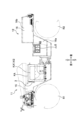
- FIG. 2 is a side view of the electric roller according to the first embodiment of the present invention.
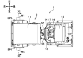
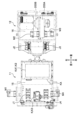
- FIG. 2 is a plan view of the electric roller according to the first embodiment.
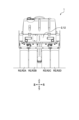
- FIG. 2 is a rear view of the electric roller according to the first embodiment.
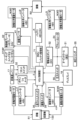
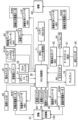
- FIG. 2 is a block diagram showing a configuration of an electric roller according to the first embodiment.
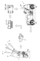
- 5A to 5C are schematic diagrams illustrating the operation of the electric roller according to the first embodiment.
- FIG. 2 is a block diagram showing a power supply system and a control system of the electric roller according to the first embodiment.
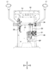
- FIG. 2 is a rear view showing the dashboard of the electric roller according to the first embodiment.
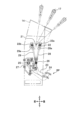
- FIG. 2 is a side view showing a dashboard of the electric roller according to the first embodiment.
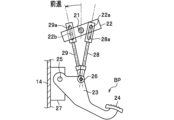
- FIG. 4 is a side view showing a brake pedal in the electric roller according to the first embodiment during forward movement.
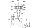
- FIG. 4 is a side view showing the electric roller according to the first embodiment when the brake pedal is depressed.
- FIG. 2 is a partially see-through side view of the electric roller according to the first embodiment.
- FIG. 2 is a partially transparent plan view of the electric roller according to the first embodiment.
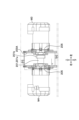
- FIG. 2 is a cross-sectional view showing a front wheel of the electric roller according to the first embodiment.
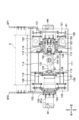
- FIG. 2 is a plan view showing a first gear box of the electric roller according to the first embodiment. This is a cross-sectional view taken along the line XV-XV of Figure 14.
- 16 is a cross-sectional view taken along line XVI-XVI of FIG. 14 .
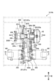
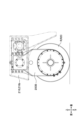
- FIG. 2 is a cross-sectional view showing the periphery of a rear wheel of the electric roller according to the first embodiment.
- 18 is a cross-sectional view taken along line XVIII-XVIII of FIG. 17.
- FIG. 2 is a side view showing the steering system of the electric roller according to the first embodiment.
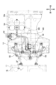
- FIG. 2 is a plan view showing a steering system for the electric roller according to the first embodiment.
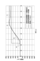
- 11 is a graph showing the relationship between time and rotation speed at startup in a comparative example. 11 is a graph showing the relationship between time and rotation speed in a comparative example when the engine is stopped.
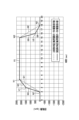
- 10 is a graph showing the relationship between time and rotation speed of the driving command value of the electric motor for the rolling wheel in the comparative example and the embodiment.
- FIG. 4 is a graph showing the relationship between time and rotation speed at start-up in an embodiment.
- 11 is a graph showing the relationship between time and rotation speed in an embodiment when the engine is stopped.
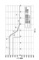
- 13 is a graph showing a drive command value of an electric motor for a rolling wheel according to a modified example, relative to time and rotation speed.
- FIG. 11 is a cross-sectional view showing a front wheel of an electric roller according to a fourth embodiment.
- FIG. 13 is a block diagram showing a configuration of an electric roller according to a fourth embodiment.
- FIG. 13 is a plan view showing the upper surface of a dashboard of an electric roller according to a fourth embodiment.
- FIG. 11 is a block diagram showing a power supply system and a control system of an electric roller according to a fourth embodiment.
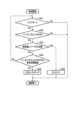
- FIG. 13 is a flow diagram of a control unit of an electric roller according to a fourth embodiment, illustrating the flow of auto standby control.
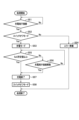
- FIG. 13 is a flow diagram of a control unit of an electric roller according to a fourth embodiment, illustrating a flow of normal charging.
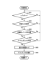
- FIG. 13 is a flow diagram of a control unit of an electric roller according to a fourth embodiment, illustrating a flow for starting a charging mode during travel.
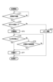
- FIG. 13 is a flow diagram of a control unit of an electric roller according to a fourth embodiment, illustrating a flow of charging during travel.
- FIG. 13 is a flow diagram of a control unit of an electric roller according to a fourth embodiment, illustrating a flow for ending a charging mode during travel.
- the electric roller 1 mainly comprises a front wheel R1, a rear wheel R2, a body frame 2, an electric motor M (M1 to M4), an inverter J (J1 to J4), a battery K (K1 to K3), and a control unit 3.
- the front wheel R1 is rotatably supported by a pair of front wheel side plates SP1, SP2 provided at the front of the body frame 2.
- the front wheel R1 is a rolling wheel that rolls the road surface, and in this embodiment is composed of an integrated iron wheel.
- the front wheel R1 may be composed of multiple tires or multiple iron wheels.
- the rear wheels R2 are rotatably supported at the rear of the body frame 2.
- the rear wheels R2 are rolling wheels that roll the road surface, and in this embodiment are composed of four tires (R2A, R2B, R2C, R2D).
- the rear wheels R2 may also be composed of a single or multiple iron wheels.
- the vehicle frame 2 is a vehicle body that rotatably supports the front wheels R1 and the rear wheels R2.
- the vehicle frame 2 includes a front frame 11, a rear frame 12, a driver's seat 13, and a dashboard 14.
- the front frame 11 has front wheel side plates SP1, SP2 fixed to the front. Inside the front frame 11, a front space 15 is formed to accommodate an inverter J and a battery K.
- the rear frame 12 includes a driver's seat 13 and a dashboard 14, and a rear space 16 is formed inside to accommodate an electric motor M, an inverter J, a gear box, etc.
- the rear space 16 includes a first rear space 16a formed below the feet of the driver's seat 13, and a second rear space 16b formed below the driver's seat 13.
- the front frame 11 and the rear frame 12 are connected via joint pins that are parallel to the vertical direction.
- the electric roller 1 of this embodiment is an articulated type, but may be a rigid type.
- the front wheel electric motor M1 is an electric motor that drives the front wheel R1.
- the front wheel electric motor M1 drives according to a drive command value input from the control unit 3 to the front wheel inverter J1.
- the right rear wheel electric motor M2 is an electric motor that drives the rear wheel R2.
- the right rear wheel electric motor M2 drives according to a drive command value input from the control unit 3 to the right rear wheel inverter J2.
- the left rear wheel electric motor M3 is an electric motor that drives the rear wheel R2.
- the left rear wheel electric motor M3 drives according to a drive command value input from the control unit 3 to the left rear wheel inverter J3.
- the front wheel electric motor M1, the right rear wheel electric motor M2, and the left rear wheel electric motor M3 are collectively referred to as the "electric motors for rolling wheels.”
- the front wheel inverter J1, the right rear wheel inverter J2, and the left rear wheel inverter J3 are collectively referred to as the "inverters for rolling wheels.”
- the vibration electric motor M4 is an electric motor that drives the vibration shaft 130.
- the vibration electric motor M4 is driven according to a drive command value input from the control unit 3 to the vibration inverter J4.
- the battery K is a component that supplies power to each component such as the electric motor M and the inverter J.
- the battery K includes a 48V battery K1, a 24V battery K2, and a 12V battery K3, and is stored in a battery case KA (see FIG. 11) arranged in the front space 15.
- the 48V battery K1 and the 24V battery K2 are lithium-ion secondary batteries.
- the 12V battery K3 is a lead-acid battery.
- three types of batteries with different voltages are provided for the battery K, but any number of types may be used, or the battery may be configured with a single voltage.
- the battery management unit 71 uses, for example, a BMU (Battery Management Unit).
- the control unit 3 is a controller that controls each component.
- the control unit 3 uses, for example, a VCU (Vehicle Control Unit).
- VCU Vehicle Control Unit
- the battery K, the battery management unit 71, and the control unit 3 are capable of cooperating with each other through CAN communication for transmitting battery information.
- the control unit 3 outputs a drive command value to the inverters J (J1 to J3) according to the tilt angle of the forward/reverse lever 17 by the operator OP.
- the electric motors M (M1 to M3) rotate according to the drive command value input to each inverter J, causing the vehicle to travel forward or backward.
- fuel such as gasoline was burned to operate a hydraulic pump using an internal combustion engine (engine, etc.) to drive the rolling wheels, whereas the electric roller 1 of this embodiment differs in that it does not have an internal combustion engine and the rolling wheels are powered only by a battery K.
- the acceleration and deceleration of the vehicle's traveling speed was adjusted by hydraulic control, whereas the electric roller 1 of this embodiment differs in that it is controlled by a drive command value output from the control unit 3 to the inverter J.
- the driver's seat 13 is a portion where an operator OP sits, and faces a dashboard 14.
- the dashboard 14 is a box-shaped body installed in front of the driver's seat 13, and is provided with a brake pedal BP protruding rearward, and a display 18 is disposed on the upper surface.
- the steering wheel 19 is a device for determining the traveling direction of the vehicle, and is provided on the upper surface of the dashboard 14.
- the steering wheel 19 is connected to an orbitroll (registered trademark, the same applies below; see Figs. 4 and 19) 51 provided inside the dashboard 14.
- the brake pedal BP is provided at the bottom rear of the dashboard 14 and is configured so that the brakes are activated when the operator OP steps on it.
- the forward/reverse levers 17, 17 are provided on both sides of the dashboard 14 and are levers that can be tilted to a neutral position, a forward position, and a reverse position.
- the forward/reverse lever 17 may be configured to be provided on only one side of the dashboard 14.
- the forward/reverse levers 17, 17 are connected to both ends of a shaft 21.
- the shaft 21 is disposed inside the dashboard 14 along the width direction of the vehicle.
- the shaft 21 is provided with a plate-shaped base plate 22 that rotates in sync with the shaft 21 and is fixed perpendicular to the shaft 21.
- the brake pedal BP is configured to move in conjunction with the shaft 21.
- a first pin 22a and a second pin 22b that protrude in the width direction of the vehicle are formed on the base plate 22.
- the first pin 22a and the second pin 22b are positioned approximately equidistant from the shaft 21.
- the brake pedal BP includes a main body plate 23, a pedal portion 24, a pivot portion 25, and a connecting pivot portion 26.
- the main body plate 23 is a plate-like member with a pedal portion 24 at the rear.
- the front end of the main body plate 23 is rotatably fixed via a bracket 27 fixed to the front wall of the dashboard 14.
- the pivot point portion 25 is the center of rotation of the brake pedal BP.
- the connecting point portion 26 is formed on the upper part of the main body plate 23.
- the connecting fulcrum 26 is connected to the base plate 22 via a first brake pedal rod 28 and a second brake pedal rod 29.
- the first brake pedal rod 28 and the second brake pedal rod 29 are rod-shaped members.
- the lower ends of the first brake pedal rod 28 and the second brake pedal rod 29 are connected to the connecting fulcrum 26 by a pin connection.
- the upper end of the first brake pedal rod 28 is formed with a long hole 28a into which the first pin 22a fits loosely.
- the upper end of the second brake pedal rod 29 is formed with a long hole 29a into which the second pin 22b fits loosely.
- the base plate 22 In the initial position (when the forward/reverse lever 17 is in the neutral position), the base plate 22 is generally horizontal. In addition, the first pin 22a and the second pin 22b are located slightly above the center in the height direction in the long holes 28a and 29a.
- the base plate 22 rotates clockwise in sync with the shaft 21.
- the first pin 22a and the second pin 22b move within the long holes 28a, 29a, respectively, so the position of the brake pedal BP does not change.
- Figure 10 is a diagram of the operation around the base plate 22 when the brake pedal BP is depressed.
- the brake pedal BP rotates downward around the pivot fulcrum 25.
- the first brake pedal rod 28 and the second brake pedal rod 29 are pulled downward, so that the first pin 22a and the second pin 22b are positioned at the upper ends of the long holes 28a and 29a, respectively, and the base plate 22 rotates by a predetermined angle and becomes approximately horizontal.
- the shaft 21 and forward/reverse lever 17 also rotate and are positioned in the neutral position, so that the brake is activated and braking is performed.
- the operator OP can return the forward/reverse lever 17 to the neutral position or depress the brake pedal BP, thereby positioning the forward/reverse lever 17 in the neutral position and braking the vehicle. Details of the brake system will be described later.
- a potentiometer 31 is installed inside the dashboard 14.
- the potentiometer 31 is a device that detects the tilt angle of the forward/reverse lever 17.
- the shaft 21 is provided with a connecting plate 34 that protrudes in a direction perpendicular to the axial direction.
- the potentiometer 31 is provided with a connecting plate 35 that is connected to the potentiometer 31 and rotates in synchronization with the connecting plate 34.
- a connecting rod 33 is provided that connects the connecting plates 34, 35 together.
- a limit switch (neutral sensor) 32 is installed inside the dashboard 14 near the shaft 21.
- the limit switch 32 is a device that detects the neutral position of the forward/reverse lever 17. The detection result of the limit switch 32 is output to the control unit 3.
- the display 18 provided on the top surface of the dashboard 14 displays various vehicle information held by the control unit 3, such as a speedometer, remaining battery power, mileage, hour meter, and alert information.
- the display 18 may be configured to display a touch-type operation panel.
- the display 18 may also display information related to compaction, such as the compaction status of the construction site, map information of the compacted area, and location information.
- a driving H/L switch 36, a parking switch 37, a vibration switch 39, a lighting switch, an alarm switch, etc. are provided on the top surface of the dashboard 14.
- the travel H/L switch 36 is a switch that allows the selection of high-speed travel mode or low-speed travel mode.
- the forward/reverse lever 17 is fully tilted (full throttle), for example, the high-speed travel mode is set to 10 km/h and the low-speed travel mode is set to 5 km/h. These speeds can be set as appropriate.
- the parking switch 37 is a switch that can select whether to activate or release the parking brake.
- the vibration switch 39 is a switch that can select whether to turn the vibration of the front wheel R1 ON or OFF.
- a switch that can control the intensity (rpm) of the vibration in conjunction with the vibration switch 39 may be provided.
- the lighting switch is, for example, a switch that can select whether to turn on or off the hazard lights that flash when stopping.
- the alarm switch is, for example, a switch that can select whether to turn on or off the backup buzzer when backing up.
- the ON or OFF state of these function switches (buttons) may be displayed on the display 18.
- the inverter J includes a front wheel inverter J1, a right rear wheel inverter J2, a left rear wheel inverter J3, and a vibration inverter J4.
- the inverter J is a device that controls the frequency based on the drive instruction value output from the control unit 3 and changes the rotation speed of each electric motor M.
- the electric motors M include a front wheel electric motor M1, a right rear wheel electric motor M2, a left rear wheel electric motor M3, and a vibration electric motor M4.
- the type of electric motor M may be selected as appropriate, but in this embodiment, induction motors are used for all of them.
- the front wheel R1 is equipped with a roll 111, and a front wheel electric motor M1 and a vibration electric motor M4 are installed at both ends in the width direction of the vehicle.
- the roll 111 has a hollow cylindrical shape, and a first mirror plate 112 and a second mirror plate 113 are provided on the inner surface of the roll 111 with a gap therebetween.
- a hollow cylindrical vibration exciter case 114 is fixed between the first mirror plate 112 and the second mirror plate 113.
- the inside of the vibration exciter case 114 is filled with lubricating oil.
- a first holder 115 is attached to the first mirror plate 112, and a second holder 116 is attached to the second mirror plate 113.
- the first holder 115 is supported by a cylindrical housing 118 via a bearing 117.
- the housing 118 hangs down from the left side surface of the body frame 2 , and its lower end is attached to the front wheel side plate SP 1 located inside the roll 111 via vibration isolating rubber 121 and a support member 122 .
- the second holder 116 is fixed to the second mirror plate 113.
- the front wheel electric motor M1 is attached via a motor mounting plate 124 to the front wheel side plate SP2, which hangs down from the right side of the body frame 2 and has its lower end located at the roll 111.
- a reduction gear mechanism 125 is installed on the output section M1a of the front wheel electric motor M1.
- the output section M1a is connected to the second mirror plate 113 via vibration isolating rubber 123 and a support member 126.
- a cover 127 that covers the right end section is attached to the second holder 116.
- the vibration electric motor M4 is attached via a motor mounting plate 128 connected to the front wheel side plate SP1.
- a joint member e.g., a constant velocity joint
- 129 connects the output shaft of the vibration electric motor M4 to the vibration generating shaft 130.
- the vibration generating shaft 130 is disposed within the vibration generating case 114 and extends in the vehicle width direction around an axis that is coaxial with the roll 111.
- the vibration generating shaft 130 comprises a main body 131, support shafts 132 and 133 provided at both ends of the main body 131, and an eccentric weight 134.
- the main body 131 is an axially shaped portion, and support shafts 132 and 133 having a smaller diameter than the main body 131 are provided at both ends.
- the support shaft 132 is supported by the first holder 115 via a bearing 135.
- the support shaft 133 is supported by the second holder 116 via a bearing 136.
- the eccentric weight 134 is provided on the outer circumferential surface of the main body 131.
- the vibration electric motor M4 rotates, the rotational force is transmitted to the vibration shaft 130 via the joint member 129, and the vibration shaft 130 rotates relative to the first holder 115 and the second holder 116. At that time, the roll 111 vibrates because the vibration shaft 130 is equipped with an eccentric weight 134.
- a vibration signal is output from the control unit 3 to the vibration inverter J4, and the vibration electric motor M4 operates based on the drive instruction value of the vibration inverter J4.
- a new operation switch may be provided to provide, for example, a high vibration mode or a low vibration mode.
- the vibration electric motor M4 When the vibration electric motor M4 is rotated at high speed, the vibration increases, and when rotated at low speed, the vibration decreases.
- the rotation speed of the vibration electric motor M4 may be freely controlled according to the operation of the operator OP, so that the strength of the vibration can be adjusted.
- the vibration shaft 130 (vibration system) is provided only on the front wheel R1, but it may also be provided on the rear wheel R2, or only on the rear wheel R2.
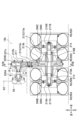
- ⁇ Reduction mechanism> As shown in Figures 14 to 18, the rotational forces of the right rear wheel electric motor M2 and the left rear wheel electric motor M3 are transmitted to the rear wheel R2 via a reduction mechanism.
- the reduction mechanism is made up of a first gear box 200A and a second gear box 200B, and is provided from the second rear space 16b of the rear space 16 to the rear wheel R2.
- the right rear wheel electric motor M2 and the left rear wheel electric motor M3 are arranged such that their output shafts face each other and are parallel to the vehicle width direction.
- the first gearbox 200A includes a first gear 201, a second gear 204, a third gear 205, and a fourth gear 207.
- the first gearbox 200A is a rectangular box-shaped body and is disposed inside the second rear space 16b.
- the first gear 201, the second gear 204, the third gear 205, and the fourth gear 207 all have rotation axes that are parallel to the vehicle width direction.
- the inside of the first gearbox 200A is filled with lubricating oil.
- the first gear 201 has a shaft portion 201a and a gear portion 201b provided on the shaft portion 201a. Both ends of the shaft portion 201a are connected to the output shafts of the electric motor M2 for the right rear wheel and the electric motor M3 for the left rear wheel, respectively, and are supported by bearings 202, 202 provided in the first gear box 200A.
- the second gear 204 has a shaft portion 204a, and a large diameter gear 204b and a small diameter gear 204c provided on the shaft portion 204a. Both ends of the shaft portion 204a are supported by bearings 203, 203 provided in the first gear box 200A.
- the large diameter gear 204b is meshed with the gear portion 201b of the first gear 201 and the gear portion 205b of the third gear 205.
- the small diameter gear 204c is meshed with the large diameter gear 207b of the fourth gear 207.
- the third gear 205 has a shaft portion 205a and a gear portion 205b provided on the shaft portion 205a.
- the shaft portion 205a is supported by a bearing 206 provided on the first gear box 200A.
- a non-excitation brake (negative brake) 62 is connected to the tip of the shaft portion 205a. In other words, the non-excitation brake 62 is connected to the outside of the first gear box 200A via the shaft portion 205a.
- the fourth gear 207 has a shaft portion 207a, and a large diameter gear 207b and a small diameter gear 207c provided on the shaft portion 207a.
- the shaft portion 207a communicates with the first gear box 200A and the second gear box 200B, and is supported by bearings 209, 209 provided on the second gear box 200B.
- a seal member 208 is interposed between the first gear box 200A and the outer periphery of the shaft portion 207a.
- the large diameter gear 207b is disposed in the first gear box 200A, and is engaged with the small diameter gear 204c of the second gear 204.
- the small diameter gear 207c is disposed in the second gear box 200B.
- the second gear box 200B is arranged next to the first gear box 200A, and is a vertically long box-shaped body arranged from the second rear space 16b to the rear wheel R2.
- the fifth gear 210 has a shaft portion 210a and a gear portion 210b provided on the shaft portion 210a.
- the shaft portion 210a is supported by a bearing 211 provided on the second gear box 200B.
- the gear portion 210b is meshed with the small diameter gear 207c of the fourth gear 207 and the gear portion 213b of the sixth gear 213, respectively.
- the sixth gear 213 has a shaft portion 213a and a gear portion 213b provided on the shaft portion 213a.
- the shaft portion 213a is a shaft that extends across the tires R2A to R2D of the rear wheel R2.
- Holders 218A and 218B that extend to the left and right in the vehicle width direction and support the shaft portion 213a via bearings 214 are respectively provided at the bottom of the second gearbox 200B.
- the left end of the shaft portion 213a is fastened to the hub 216A via a fastening portion 217A.
- the hub 216A supports the disc wheels DWA and DWB that are placed inside the tires R2A and R2B.
- the right end of the shaft portion 213a is fastened to the hub 216B via the fastening portion 217B.
- the hub 216B also supports the disc wheels DWC and DWD that are placed inside the tires R2C and R2D.
- the rotational force of the right rear wheel electric motor M2 and the left rear wheel electric motor M3 is transmitted to the shaft 213a via the first gear 201, the second gear 204, the fourth gear 207, the fifth gear 210, and the sixth gear 213, and is also transmitted to the rear wheel R2 via the hubs 216A and 216B.
- the steering system includes an orbit roll 51, an electric hydraulic pump 52, a filter 53, an accumulator 54, hydraulic cylinders 55, 55, and a pressure switch 56 (see Fig. 4). These components are connected by piping to form a hydraulic circuit in the steering system.
- the orbit roll 51 is connected to the steering wheel 19 and is disposed inside the dashboard 14.
- the electric hydraulic pump 52 is electrically connected to the 24V battery K2 and is disposed in the first rear space 16a.
- the filter 53 is connected to a part of the piping and is a member that removes impurities such as dust and iron contained in the hydraulic oil.
- the accumulator 54 is connected to a part of the piping and is a device that stores and releases the fluid energy of the hydraulic oil.
- the filter 53 and the accumulator 54 are disposed in the second rear space 16b.
- the hydraulic cylinders 55, 55 are cylinders that connect the front frame 11 and the rear frame 12, and are disposed in pairs on both sides in the vehicle width direction. The extension and contraction of the hydraulic cylinders 55, 55 allows the vehicle to turn left and right.
- the pressure switch 56 checks the pressure in the hydraulic circuit and determines whether to start or stop the electric hydraulic pump 52.
- the control unit 3 receives a detection signal from the pressure switch 56 and the pressure in the hydraulic circuit drops below a predetermined value, it starts the electric hydraulic pump 52, and when the pressure is above the predetermined value, it stops the electric hydraulic pump 52.
- the pressure switch 56 can also detect pressure errors in the hydraulic circuit.
- the steering system includes an electric hydraulic pump 52, hydraulic cylinders 55, 55 driven by the pressurized oil discharged from the electric hydraulic pump 52, and a steering valve (not shown) that controls the direction and flow rate of the pressurized oil supplied from the electric hydraulic pump 52 to the hydraulic cylinders 55, 55.
- the steering valve is switched according to the direction and amount of rotation of the steering wheel 19 to drive and control the hydraulic cylinders 55, 55.
- the switching of the steering valve according to the direction and amount of rotation of the steering wheel 19 is performed by the orbit roll 51.
- Neutral brake is a brake that is activated when the forward/reverse lever 17 is placed in the neutral position by the operator OP, as shown in Fig. 4.
- the vehicle is decelerated by applying regenerative motion and reverse braking of the electric motor for the rolling wheels, and is electrically stopped by the zero rotation speed holding brake (excitation brake 61).
- the excitation brake 61 is a brake that is activated when energized and released when de-energized.
- the limit switch 32 When the forward/reverse lever 17 is in the neutral position, the limit switch 32 outputs a detection signal to the control unit 3.
- the control unit 3 outputs drive command values to the front wheel inverter J1, the right rear wheel inverter J2, and the left rear wheel inverter J3 so that the front wheel electric motor M1, the right rear wheel electric motor M2, and the left rear wheel electric motor M3 are each at 0 rotations.
- the control unit 3 also outputs a brake signal to the excitation brake 61.
- the control unit 3 After a predetermined time has elapsed since the control unit 3 output the drive command values (maintaining 0 rotations) to each inverter J, the control unit 3 releases the brake of the excitation brake 61 while activating the non-excitation brake 62 ( Figures 4 and 14) by the activation relay.
- the predetermined time can be set as appropriate.
- the non-excitation brake 62 is controlled by an activation relay connected to the control unit 3.
- Foot brake (emergency stop)
- the foot brake is a brake that is activated by depressing the brake pedal BP, as shown in Figures 4 and 8.
- a foot brake signal is output to the control unit 3.
- the control unit 3 then cuts off the power to each electric motor M.
- the brake pedal BP is depressed, the base plate 22, which has been tilted by the mechanism in Figures 9 and 10 as described above, returns to the horizontal position. In other words, the shaft 21 (forward/reverse lever 17) is located in the neutral position, and the neutral brake described above is activated.
- the parking brake is a brake that is activated by pressing the parking switch 37, as shown in Fig. 4.
- a parking brake signal is output to the control unit 3.
- the control unit 3 activates the non-excited brake 62.
- the non-excitation brake 62 is a mechanical disk brake that operates when not energized.
- the non-excitation brake 62 is electrically connected to the 24V battery K2.
- the non-excitation brake 62 allows the rotor 64, which rotates in sync with the shaft portion 205a of the third gear 205, to rotate. This allows the third gear 205 to also rotate, enabling travel.
- the rotor 64 is clamped to prevent the shaft portion 205a from rotating, and the brake operates.
- the non-excitation brake 62 is provided with a release lever 63. The operator OP or worker can release the non-excitation brake 62 by operating the release lever 63.
- the battery K in this embodiment includes a 48V battery K1, a 24V battery K2, and a 12V battery K3.
- the 48V battery K1 and the 24V battery K2 are lithium ion batteries.
- a battery management unit (BMU) 71 is a device that measures the voltage value, current value, temperature, etc. of each battery cell and monitors and controls the battery (lithium ion secondary battery) K.
- the battery management unit 71 also has a function of displaying measured data, a balancing function of keeping the voltage between each cell constant, and a function of detecting overcharging and overdischarging.
- the battery management unit 71 and the control unit 3 are capable of communicating battery information via CAN communication.
- the 12V battery K3 is a lead-acid battery.
- the 12V battery K3 is electrically connected to a starter switch 38 that starts the electric roller 1.
- the 12V battery K3 is also electrically connected to electrical equipment including lighting devices (e.g., hazard lights) 40 and alarm devices (e.g., a backup buzzer and an alert buzzer) 41.
- the 12V battery K3 can supply electricity to start (restart) the electric roller 1 and to various electrical equipment, even when the control unit 3 has a system down.
- the 48V battery K1 is electrically connected to each inverter J and each electric motor M.
- a DC-DC converter 42 is provided between the 48V battery K1 and the 12V battery K3.
- the DC-DC converter 42 is a device that reduces the voltage in order to supply power from the 48V battery K1 to the 12V battery K3.
- the 24V battery K2 is electrically connected to the electric hydraulic pump 52 and the non-exciting brake 62.
- the control unit (VCU) 3 is a device that determines the state of the vehicle as it changes while driving and controls each part to maintain the optimum state.
- the control unit 3 controls each part, which influences each other, such as the electric motor M, inverter J, and battery K, while taking into account the influence on other parts.
- the control unit 3 includes a calculation unit (CPU: Central Processing Unit), a memory unit, a communication unit, etc.
- the control unit 3 may be located anywhere, but in this embodiment it is attached to the front of the battery case KA of the battery K (see Figure 11).
- the calculation unit is a part that reads out programs stored in the memory unit and functions as a functional unit.
- the memory unit includes a RAM (Random Access Memory), a ROM (Read Only Memory), a HDD (Hard Disk Drive), etc.
- the memory unit stores various programs and drive instruction values for each inverter J relative to the tilt angle of the potentiometer 31 as a drive instruction value file.
- the communication unit is, for example, a CAN communication, and is capable of communicating with each component.
- the control unit 3 may also be linked to a Global Navigation Satellite System (GNSS) to acquire and utilize driving records, location information, driving conditions, etc.
- GNSS Global Navigation Satellite System
- the control unit 3 may also be linked to a compaction management device equipped with a sensor that acquires road surface compaction information to acquire and utilize compaction information in real time.
- the control unit 3 may also be linked to an autonomous driving device to enable autonomous driving by remote control.
- the control unit 3 may also transmit vehicle operation information (driving time, abnormality information, battery status, etc.) to a technical center, leasing company, etc., and store and manage the information.
- a vibration signal is output to the control unit 3.
- the control unit 3 sends a vibration instruction value to the vibration inverter J4, and operates the vibration electric motor M4 based on the vibration instruction value. This causes the vibration shaft 130 to rotate, and the front wheel R1 to vibrate.
- fuel consumption and greenhouse gas emissions can be substantially eliminated by electrification. Furthermore, since noise can be reduced and greenhouse gas emissions can be substantially eliminated by electrification, the burden on the operator OP can be reduced and the working environment can be improved. Furthermore, since no hydraulic pump or hydraulic circuit is used for traveling as in the past, there is no need to change hydraulic oil, and maintenance is easy.
- multiple electric motors for the rolling wheels front wheel electric motor M1, right rear wheel electric motor M2, and left rear wheel electric motor M3 are provided. Although only one electric motor for the rolling wheels is sufficient, providing multiple motors makes it possible to increase the main torque while preventing the electric motor for the rolling wheels from becoming too large. This makes it possible to stop and start on an uphill slope.
- the potentiometer 31 since the potentiometer 31 is provided, fine speed control according to the inclination of the forward/reverse lever 17 is possible. Furthermore, since the limit switch 32 is provided, the neutral position can be detected reliably. Although it is possible to detect the neutral position using only the potentiometer 31, if an error occurs in the input from the potentiometer 31, there is a risk that the vehicle will start moving even when the forward/reverse lever 17 is in the neutral position. However, according to this embodiment, since the limit switch 32 is provided, the neutral position can be detected reliably.
- the vehicle is equipped with electrical equipment including lighting devices 40 and alarm devices 41, and is equipped with a plurality of batteries K with different voltages that are electrically connected to the electric motor for the rolling wheels and the electrical equipment, respectively.
- the 48V battery K1 and the 24V battery K2 are lithium-ion batteries (storage batteries), and therefore can be charged and used repeatedly.
- the battery K is installed in the front space 15 of the body frame 2, which allows for a more compact size by making effective use of the space.
- the battery K can be placed in the area where the engine was previously installed.
- the battery K can be protected by storing it in a battery case KA.
- the battery K may be installed only in the rear space 16, or in both the front space 15 and the rear space 16.
- the electrical equipment including the lighting device 40 and the alarm device 41 are electrically connected to the 12V battery K3, which is a lead-acid battery. This allows the electrical equipment including the lighting device 40 to function when the control unit 3 goes down. Therefore, even if the system goes down, it is possible to issue an alert to the surroundings, and the system can be smoothly restarted and restarted.
- the speedometer can be displayed on the display 18 provided on the dashboard 14, and vehicle information held by the control unit 3 can be displayed on the display 18.
- vehicle information held by the control unit 3 can be displayed on the display 18. This allows the operator OP to grasp not only the speed, but also vehicle information held by the control unit 3, such as whether the vehicle is moving forward or backward, the presence or absence of vibration, the charge level, the time, and the total distance traveled.
- a mechanism for vibrating the rolling wheels may be provided as necessary, but according to this embodiment, the vibration excitation shaft 130 is operated by a vibration inverter J4 and a vibration electric motor M4.
- a vibration inverter J4 and a vibration electric motor M4.
- electrifying the vibration excitation shaft 130 noise can be reduced and greenhouse gas emissions can be substantially eliminated, reducing the burden on the operator OP and improving the working environment.
- no hydraulic pump or hydraulic circuit for vibration is used as in the past, there is no need to change the hydraulic oil, and maintenance is easy.
- the vibrations acting on the vibration electric motor M4 can be reduced by installing the vibration electric motor M4 on the spring (above the vibration isolation rubber 121 (towards the vehicle frame 2)). Also, by providing a constant velocity joint that connects the vibration generating shaft 130 and the output shaft of the vibration electric motor M4, the drive of the vibration electric motor M4 can be transmitted to the vibration generating shaft 130 even when the operating angle is set.
- electrification can substantially eliminate fuel consumption and greenhouse gas emissions. Furthermore, electrification can reduce noise and substantially eliminate greenhouse gas emissions, thereby reducing the burden on the operator OP and improving the working environment. Furthermore, according to this embodiment, since the hydraulic cylinder 55 is driven using the electric hydraulic pump 52, changes to the mechanism around the steering can be kept to a minimum when electrification is performed.
- pressure can be accumulated in the accumulator 54, which prevents the electric hydraulic pump 52 from burning out due to continuous operation and reduces energy consumption.
- the electric hydraulic pump 52, piping, and accumulator 54 are installed in the rear space 16 of the vehicle body frame 2, making it possible to effectively utilize the rear space 16 and reducing the number of pipes and other components that need to span between the front space 15 and the rear space 16.
- the hydraulic cylinders 55 are installed on both the left and right sides of the body frame 2, so the difference in the amount of oil discharged left and right during turning can be reduced or eliminated, making it possible to stabilize behavior during turning.
- the number of hydraulic cylinders 55 per body frame 2 may be just one. This simplifies the structure and reduces the number of parts.
- the control unit 3 when the forward/reverse lever 17 is in the neutral position, the control unit 3 outputs a zero rotation signal to the inverters for the rolling wheels (front wheel inverter J1, right rear wheel inverter J2, left rear wheel inverter J3) and activates the excitation brake 61.
- This makes it possible to easily configure the brake system, and by electrifying the brake system, it is possible to substantially eliminate fuel consumption and greenhouse gas emissions. Furthermore, by electrifying the brake system, it is possible to reduce noise and substantially eliminate greenhouse gas emissions, thereby reducing the burden on the operator OP and improving the working environment. Furthermore, since a hydraulic circuit is not used in the brake system as in the past, there is no need to change hydraulic oil, and maintenance is excellent.
- control unit 3 activates the non-excited brake 62, which mechanically applies braking, after a predetermined time has elapsed since the excitation brake 61 was activated. Activating the excitation brake 61 results in continued consumption of power during stoppage, but according to this embodiment, after a predetermined time has elapsed, the control unit 3 switches to the non-excited brake 62 and releases the excitation brake 61, thereby reducing power consumption.
- the control unit 3 activates the non-excited brake 62, which mechanically applies brakes, via an operating relay. This allows the vehicle to be stopped in the event of an emergency.
- the de-energized brake 62 can be released easily.
- the electric roller 1 according to the second embodiment differs from the first embodiment in that it is provided with an over-rotation prevention mechanism that prevents over-rotation of the front wheel electric motor M1, the right rear wheel electric motor M2, and the left rear wheel electric motor M3 (electric motor for rolling wheels).
- the differences from the first embodiment will be mainly described. Note that the drive command values and times shown below are merely examples, and these numerical values can be set as appropriate.
- the inclination of the forward/reverse lever 17 of the electric roller 1 is input to the control unit 3, which outputs a drive command value for acceleration, deceleration, or stop to each inverter J.
- Each inverter J that receives the drive command value from the control unit 3 controls the running operation of the vehicle by outputting a drive command value for the number of rotations to the electric motor for the rolling wheels to accelerate or decelerate according to the input amount of the forward/reverse lever 17.
- the above-described embodiment has a problem in that the vehicle behavior is unstable when accelerating, decelerating, or stopping.
- the forward/reverse lever 17 is operated at full throttle in the forward direction during acceleration, the drive command value input to the inverter J rises in one go from 0 rotations to the target drive command value.
- the output of the electric motor for the rolling wheels is small, the inertial force generated during acceleration cannot be suppressed.
- the rotation speed of the electric motor for the rolling wheels exceeds the target drive command value due to the inertia that cannot be fully controlled.
- the electric motor for the roller wheels is controlled to apply regenerative motion and reverse braking to slow down.
- the forward/reverse lever 17 is returned from full throttle to the neutral position when decelerating or stopping, the drive command value output to the electric motor for the roller wheels drops all at once to 0 rotations.
- the braking torque generated at this time cannot be fully controlled due to insufficient output from the electric motor for the roller wheels, so a return swing occurs to the amount of braking torque that cannot be fully controlled when the vehicle is stopped.
- Figure 21 is a graph showing the relationship between time and rotation speed in a comparative example at start-up.
- the thin line indicates the input of the forward/reverse lever 17.
- the forward/reverse lever 17 is in a state where it is tilted to the maximum in the forward or reverse direction (full throttle state).
- the dotted line indicates the drive command value of the electric motor for the compaction wheels in the comparative example. In other words, it is the drive command value output from the control unit 3 to the inverter for the compaction wheels.
- the target drive command value P1 is approximately 2200 rpm.
- the point at which the forward/reverse lever 17 is input is defined as the "acceleration side command start point W1”
- the point at which the drive command value of the electric motor for the compaction wheels reaches the target drive command value P1 (the point reached in calculations)
- the line connecting the acceleration side command start point W1 and the acceleration side target rotation speed arrival point N1 is defined as the "first stage acceleration Q1".
- it is set to reach from 0 rpm to 2200 rpm in approximately 3.0 seconds.
- the thick line indicates the rotation speed (actual rotation speed) of the electric motor for the compaction wheels in the comparative example.
- the rotation speed of the electric motor for the compaction wheels in the comparative example is lower than the first stage acceleration Q1, which is the drive command value, immediately after the acceleration side command start point W1.
- the first stage acceleration Q1 which is the drive command value, immediately after the acceleration side command start point W1.
- the acceleration side target rotation speed point N1 the inertial force generated during acceleration cannot be suppressed, so the rotation speed of the electric motor for the compaction wheels exceeds the target drive command value P1 for a certain period of time.
- the rotation speed of the electric motor for the compaction wheels and the target drive command value P1 match.
- the electric motor for the compaction wheels enters an overspeed state for a certain period of time, causing the vehicle behavior to become unstable.
- FIG. 22 is a graph showing the relationship between time and rotation speed in the comparative example when stopped.
- the target drive command value P2 is 0 rpm (0 rotations).
- the point at which the forward/reverse lever 17 is returned to the neutral position from the full throttle state is defined as the "deceleration side command start point W2”
- the point at which the drive command value of the electric motor for the pressure wheels reaches the target drive command value P2 (the point it will reach in calculations) is defined as the "deceleration side target rotation speed arrival point N2”
- the straight line connecting the deceleration side command start point W2 and the deceleration side target rotation speed arrival point N2 is defined as the "first stage deceleration Q2".
- it is set to reach from 2200 rpm to 0 rpm in approximately 2.0 seconds.
- the rotation speed of the electric motor for the compaction wheels exceeds the drive command value immediately after the deceleration side command start point W2.
- the generated braking torque cannot be fully controlled due to insufficient output of the electric motor for the compaction wheels, so the rotation speed of the electric motor for the compaction wheels falls below the target drive command value P2 for a certain period of time.
- the rotation speed of the electric motor for the compaction wheels and the target drive command value P2 match.
- the electric motor for the compaction wheels goes into an over-speed state for a certain period of time after the deceleration side target rotation speed point N2, causing the vehicle behavior to become unstable (swinging back when stopped).
- ⁇ Configuration of the over-rotation prevention mechanism for the electric motor for rolling wheels, starting side> 23 is a graph showing the drive command value of the electric motor for the rolling wheel of the comparative example and the embodiment as a relationship between time and the number of revolutions.
- the solid line shows the drive command value of the electric motor for the rolling wheel of the embodiment.
- the dotted line shows the drive command value of the electric motor for the rolling wheel of the comparative example.
- the drive command value for the electric motor for the rolling wheels has an acceleration side shift point U1, as well as a first stage acceleration Q3 and a second stage acceleration Q4.
- the slope (acceleration) of the first stage acceleration Q3 is larger (steeper) than the slope (acceleration) of the first stage acceleration Q1 of the comparative example.
- the slope of the second stage acceleration Q4 is smaller (gentler) than the slope of the first stage acceleration Q1 of the comparative example.
- the slope of the second stage acceleration Q4 when approaching the acceleration side target rotation speed reaching point N1 is smaller (gentler angle) than the slope of the first stage acceleration Q1 of the comparative example. More specifically, at the start of the embodiment, the slope of the first stage acceleration Q3 is larger than the slope of the first stage acceleration Q1 (see FIG. 23) of the comparative example, so the rotation speed of the electric motor for the rolling wheels rises more rapidly than in the comparative example. Thereafter, the target drive command value P1 is reached more gently in the second stage acceleration Q4 than in the comparative example. This allows the electric motor for the rolling wheels to reach the target drive command value P1 without over-rotating (or by reducing the over-rotation). Therefore, the vehicle behavior during acceleration can be stabilized.
- the drive command value of the electric motor for the rolling wheels has a deceleration side shift point U2, and also has a first stage deceleration Q5 and a second stage deceleration Q6.
- the slope (deceleration) of the first stage deceleration Q5 is larger (steeper) than the slope (deceleration) of the first stage deceleration Q2 of the comparative example.
- the slope of the second stage deceleration Q6 is smaller (gentler) than the slope of the first stage deceleration Q2 of the comparative example.
- FIG. 25 is a graph showing the relationship between time and rotation speed in an embodiment when stopped.
- the dotted line shows the drive command value of the electric motor for the roller wheels in the embodiment.
- the solid line shows the rotation speed of the electric motor for the roller wheels in the embodiment.
- the target drive command value P2 is set to 0 rpm, and is set to reach the target drive command value P2 2.0 seconds after the forward/reverse lever 17 returns to the neutral position.
- the slope of the second-stage deceleration Q6 when approaching the deceleration side target rotation speed reaching point N2 is smaller (gentler angle) than the slope of the first-stage deceleration Q2 in the comparative example. More specifically, when the embodiment is stopped, the slope of the first-stage deceleration Q5 is larger than the slope of the first-stage deceleration Q2 (see FIG. 23) in the comparative example, so the rotation speed of the electric motor for the rolling wheels drops more sharply than in the comparative example. After that, the target drive command value P2 is reached more gently at the second-stage deceleration Q6. This allows the electric motor for the rolling wheels to reach the target drive command value P2 without over-rotating (or by reducing the over-rotation). This prevents swinging back during deceleration and stabilizes the vehicle behavior.
- FIG. 26 is a graph showing the drive command value of the electric motor for the compaction wheel in the modified example in terms of time and rotation speed.
- acceleration or deceleration occurs in three stages.
- the drive command value of the electric motor for the compaction wheel on the starting side in the modified example has shift points U3 and U4, as well as a first stage acceleration Q11, a second stage acceleration Q12, and a third stage acceleration Q13.
- the third stage acceleration Q13 approaches the acceleration side target rotation speed arrival point N1.
- the slope of the third stage acceleration Q13 is smaller (gentler angle) than the first stage acceleration Q1 in the comparative example. This makes it possible to prevent over-rotation of the electric motor for the compaction wheel, just like in the second embodiment.
- the drive command value of the electric motor for the rolling wheel on the stop side in the modified example includes speed change points U5 and U6, as well as a first-stage reduction gear Q14, a second-stage reduction gear Q15, and a third-stage reduction gear Q16.
- the third-stage reduction gear Q16 faces the reduction-side target rotation speed reaching point N2.
- the slope of the third-stage reduction gear Q16 is smaller (gentler angle) than the first-stage reduction gear Q2 in the comparative example. This makes it possible to prevent over-rotation of the electric motor for the rolling wheel, just like in the second embodiment.
- two or more speed change points may be provided on the start side or the stop side.
- the over-rotation prevention mechanism for the electric motor for the rolling wheels has at least one speed change point in the drive command value for the electric motor for the rolling wheels, and the slope approaching the acceleration side target speed reaching point N1 and the deceleration side target speed reaching point N2 is set to be smaller than the slope in the comparative example. This allows signals to be output to the inverter for the rolling wheels in multiple stages of speed change ranges, allowing the electric motor for the rolling wheels to gradually reach the target speed.
- a reference slope (here, the slope of the first stage acceleration Q1 and first stage deceleration Q2 in the comparative example) is set from the acceleration side target speed arrival point N1 and the deceleration side target speed arrival point N2, and the slope is set so as to be smaller (the angle is gentler) than the slope.
- the drive command value of the electric motor for the rolling wheel over-speed prevention mechanism may be set based on a drive command value file that is preset according to the tilt angle of the forward/reverse lever 17.
- the drive command value file is a data file in which the shift points are preset according to, for example, the tilt angle of the forward/reverse lever 17, the target drive command value, the arrival time, etc.
- the drive command value file is stored in the memory unit of the control unit 3.
- the drive command value for the over-rotation prevention mechanism of the electric motor for the roller wheels may be calculated appropriately by the control unit 3, for example, from the detected tilt angle of the forward/reverse lever 17.
- the electric roller 1 according to the third embodiment differs from the first embodiment in that it is provided with an over-rotation prevention mechanism for the vibrating electric motor that prevents over-rotation of the vibrating electric motor M4 in the vibration system.
- the differences from the first embodiment will be mainly described.
- the vibration electric motor M4 also has an eccentric weight 134 on the vibration generating shaft 130, and therefore may over-revolve relative to the target drive command value when starting and stopping vibration. This causes the vehicle behavior to become unstable, giving the operator OP a sense of discomfort.
- the mechanism for preventing over-rotation of the vibration electric motor provides a speed change point in the drive command value output from the control unit 3 to the vibration inverter J4.
- the method of setting the speed change point is the same as in the second embodiment, so a detailed description will be omitted.
- the control unit 3 outputs a signal to the vibration inverter J4 at a speed change range divided into multiple stages during vibration generation, so that the vibration electric motor M4 gradually reaches the target rotation speed. As a result, the vibration electric motor M4 gradually reaches the target rotation speed, and therefore unstable vibration behavior caused by over-rotation can be suppressed.
- control unit 3 when vibration is stopped, the control unit 3 outputs a signal to the vibration inverter J4 in multiple speed ranges to stop the vibration gradually. This suppresses the swing back phenomenon of the vibration excitation shaft 130, and allows the vibration excitation shaft 130 to be stopped stably.
- the front wheel R1D is equipped with a roll 111D, and a front wheel electric motor M1 and a vibration electric motor M4 are installed at both ends of the vehicle width direction.
- the front wheel R1D has a longer roll 111D and a shorter vibration shaft 130 compared to the structure of the first embodiment described above. This allows each part, including the front wheel electric motor M1 and the vibration electric motor M4, to be stored inside the roll 111D. Therefore, when performing compaction work, the roll 111D can be moved as close as possible to other structures, etc., improving operability.
- the other structure of the front wheel R1D is generally the same as that of the first embodiment, so the same reference numerals as in the first embodiment are used and explanations are omitted.
- the electric roller 1D is equipped with a water sprinkler switch 81 for sprinkling water, a liquid agent switch 82 for spraying liquid agent, a vibration H/L switch 83 for changing the vibration frequency, a speed change switch 84 for changing the vehicle speed, a hazard switch (light switch) 85, a buzzer switch (alarm switch) 86, and a headlamp switch (light switch) 87.
- a watering switch 81 As shown in FIG. 29, on the top surface of the dashboard 14D, a watering switch 81, a liquid agent switch 82, a vibration H/L switch 83, a gear shift switch 84, a hazard switch 85, a buzzer switch 86, a headlight switch 87, a parking switch 37, and a vibration switch 39 are provided around the display (e.g., a liquid crystal display) 18.
- the display e.g., a liquid crystal display
- the water sprinkler switch 81 is electrically connected to the control unit 3D and is a switch that controls whether or not water is sprinkled by the water sprinkler unit (not shown). When the water sprinkler switch 81 is turned ON, water is sprinkled onto the roll 111D via the control unit 3D and the water sprinkler unit (not shown), and when it is turned OFF, water sprinkling stops.
- the liquid agent switch 82 is electrically connected to the control unit 3D and is a switch that starts or stops the spraying of the liquid agent via the liquid agent spraying unit (not shown). When the liquid agent switch 82 is turned ON, the liquid agent is sprayed onto the roll 111D via the control unit 3D and the liquid agent spraying unit (not shown), and when it is turned OFF, the spraying of the liquid agent stops.
- the vibration H/L switch 83 is electrically connected to the control unit 3D, operates in conjunction with the vibration switch 39, and is a switch that selects high-speed vibration mode or low-speed vibration mode.
- the high-speed vibration mode is a mode in which the vibration electric motor M4 rotates at high speed to increase the vibration force
- the low-speed vibration mode is a mode in which the vibration electric motor M4 rotates at low speed to decrease the vibration force.
- the speed change switch 84 is electrically connected to the control unit 3D and is a switch that changes the vehicle speed.
- two speed levels could be selected with the travel H/L switch 36, but in this embodiment, a multi-speed structure with three or more speed levels is used.
- Hazard switch 85 is a switch that turns the hazard warning lamps ON or OFF.
- Buzzer switch 86 is a switch that turns ON or OFF the alarm 41 that outputs an alarm sound.
- Headlight switch 87 is a switch that turns the headlights ON or OFF. For the headlights, high beam or low beam can be selected.
- the hazard switch 85, buzzer switch 86, and headlight switch 87 are also electrically connected to the control unit 3D, and each operation can be controlled and managed.
- each switch may be displayed on the display 18 at any time.
- the electric hydraulic pump 52 was powered by the 24V battery K2, but it may be powered by the 48V battery K1 as in this embodiment shown in Figures 28 and 30.
- the electric roller 1D has a terminal 91 electrically connected to a 48V battery K1 and a 24V battery K2 (hereinafter also referred to as "batteries K1, K2").
- a rechargeable battery K4 is electrically connected to a terminal 92.
- the rechargeable battery K4 is for charging the batteries K1, K2 by connecting the terminals 91, 92.
- the electric roller 1D (control unit 3D) according to this embodiment has five basic control modes for the running state of the electric roller 1D: “switch off mode,” “standby mode,” “ready mode,” “run mode,” and “charging mode,” as well as “torque up mode” and “charging while running mode.”
- Each of these modes can be switched by the operator OP operating the starter switch 38 (number of times, time, etc.) or by a specified input operation (including operation of the starter switch 38).
- the starter switch 38 corresponds to a key cylinder that is operated by inserting an ignition key in a vehicle powered by an internal combustion engine, i.e., an engine vehicle.
- the control unit 3D can, for example, display each of these modes (excluding the switch-off mode) on the display 18. This allows the operator OP to understand the state (mode) of the vehicle.
- the control unit 3D is in the switch-off mode when the starter switch 38 is in the switch-off state.
- the switch-off mode corresponds to a state in which the ignition key is removed from the key cylinder in an engine vehicle.
- the power is turned off (the control unit (VCU) 3D is not started either), so the electric roller 1D is unable to run.
- the energy consumption in the switch-off mode (the power consumption of the 48V battery K1 and the 24V battery K2) is zero.
- the forward/reverse lever 17 is set to the neutral position by the operation of the operator OP, and the parking switch 37 is set to ON by the operation of the operator OP (i.e., the parking brake is activated).
- the standby mode is a mode in which the vehicle is in a standby state before traveling.
- the standby mode corresponds to a state in which the main switch is turned on and power can be supplied to electrical equipment (such as a display) in an engine vehicle by turning the ignition key one step while it is inserted in the key cylinder.
- the control unit 3D is started by power being supplied from the 12V battery K3 (lead storage battery), but the control unit 3D does not start the inverter J (the inverter for the rolling wheels), so the electric roller 1D is in a state in which it cannot travel.
- the energy consumption in the standby mode (the power consumption of the 48V battery K1 and the 24V battery K2) is zero.
- the ready mode described later may be designed to automatically switch to the standby mode under a predetermined condition (for example, when no operation is performed for a long time during the ready mode). Details of the specification will be described later.
- the control unit 3D goes from standby mode to ready mode by the operator OP operating the starter switch 38 (number of times, time, etc.) or by a specified input operation.
- the ready mode corresponds to a state in which the engine is driven by turning the ignition key one step further from the standby state in an engine vehicle.
- the ready mode is a state in which the inverter J is started (the forward/reverse lever 17 is in the neutral position) under the control of the control unit 3D, thereby enabling the electric roller 1D to travel.
- the amount of energy consumed in the ready mode (the amount of power consumed by the 48V battery K1 and the 24V battery K2) is very small.
- the control unit 3D switches from the ready mode to the run mode when the forward/reverse lever 17 is operated and set to the forward position or the reverse position.
- the run mode is a mode that switches by tilting the forward/reverse lever 17 and enters a traveling state.
- the electric motor M is driven by tilting the forward/reverse lever 17, and when the torque of the electric motor M exceeds a predetermined value, the parking brake (non-excited brake 62) is automatically released and the electric roller 1D starts traveling.
- the energy consumption power consumption of the 48V battery K1 and the 24V battery K2
- the electric roller 1D may start traveling by tilting the forward/reverse lever 17 after the operator OP manually releases the parking brake.
- ⁇ Charging mode (normal charging mode)>
- the control unit 3D switches from the switch-off mode to the charging mode in response to a predetermined input operation by the operator OP (e.g., connection of charging terminals 91, 92 (charging cable)) while in the switch-off mode.
- the control unit 3D executes charging by allowing charging of the 48V battery K1 and the 24V battery K2 from the charging battery K4 as a charging power source.
- the charging battery K4 may be an external power source or a battery that can be loaded on the electric roller 1D. Details of the charging mode (normal charging mode) will be described later.
- ⁇ Torque up mode> When a predetermined input operation is performed in the ready mode, the control unit 3D switches from the ready mode to the torque-up mode. In the torque-up mode, the control unit 3D temporarily increases the upper limit of the torque output of the inverter J.
- the control unit 3D switches from the ready mode to the in-travel charging mode.
- the control unit 3D allows charging of the 48V battery K1 and the 24V battery K2 from the charging battery K4 while the vehicle is traveling.
- the charging battery K4 can be loaded on the electric roller 1D and does not interfere with the traveling of the electric roller 1D.
- the control unit 3D can cause the vehicle to travel when the forward/reverse lever 17 is operated to be set to the forward position or the reverse position.
- the control unit 3D drives the electric motor M to make the electric roller 1D in a travel-enabled state.
- the control unit 3D ends the charging mode during travel and switches from the charging mode during travel to the ready mode or to a simple run mode.
- a predetermined charging rate e.g., full charge (SoC: 100%)
- SoC full charge
- a predetermined input operation disconnection of the charging terminals 91, 92 (charging cables)
- the control unit 3D can obtain the charging rates of the 48V battery K1 and the 24V battery K2 detected and calculated by the BMU 71 and use them for the determination. Details of the charging mode during travel will be described later.
- the control unit 3D judges whether or not the vehicle is in the ready mode in step S41, and judges the state of the parking switch 37 (i.e., the state of the parking brake) in step S42.
- the control unit 3D also judges the state of the forward/reverse lever 17 in step S43, and judges whether a predetermined time has elapsed in the ready mode, the parking switch 37 is OFF (the parking brake is released), and the forward/reverse lever 17 is in the neutral position in step S44.
- step S41 When the control unit 3D is in the ready mode (Yes in step S41), the parking switch 37 is OFF (Yes in step S42), and the forward/reverse lever 17 is in the neutral position (Yes in step S43) for a predetermined time (Yes in step S44), the control unit 3D switches from the ready mode to the standby mode (step S45).
- step S41 when the control unit 3D is in the ready mode (Yes in step S41), the parking switch 37 is OFF (Yes in step S42), and the forward/reverse lever 17 is in the neutral position (Yes in step S43) for a predetermined time (No in step S44), and the forward/reverse lever 17 is operated to the forward position or reverse position (No in step S43), the control unit 3D switches from the ready mode to the run mode (step S46).
- step S41 the ready mode state (Yes in step S41), the parking switch 37 is OFF (Yes in step S42) and the forward/reverse lever 17 is in the neutral position (Yes in step S43) for a predetermined time (No in step S44), the ready mode is no longer available (No in step S41) or the parking switch 37 is turned ON (the parking brake is applied) (No in step S42).
- the control unit 3D determines whether the terminals 91, 92 are connected in step S51, and determines whether the switch-off mode is set in step S52.
- the control unit 3D also determines whether the charging rates of the batteries K1, K2 are equal to or higher than a predetermined value in step S55, and determines whether the terminals 91, 92 are connected in step S56.
- control unit 3D detects a connection between the terminals 91, 92 (Yes in step S51), if the mode is switch-off mode (Yes in step S52), it switches from switch-off mode to charging mode to allow charging, and starts charging the batteries K1, K2 from the charging battery K4 (step S53).
- the control unit 3D detects a connection between the terminals 91, 92 (Yes in step S51) but is not in charging mode (and is not in charging while driving mode) (No in step S52), it rejects charging and causes the alarm 41 to sound an error sound (step S54).
- step S53 After executing step S53, if the charging rate (SoC: State of Charge) of batteries K1, K2 is less than a predetermined value (e.g., 100%) (No in step S55) and terminals 91, 92 are connected (No in step S56), the flow returns to step S55 and the control unit 3D continues charging batteries K1, K2. On the other hand, after executing step S53, if the charging rate of batteries K1, K2 is equal to or greater than a predetermined value (e.g., 100%) (Yes in step S55), the control unit 3D terminates charging batteries K1, K2 (step S57) and switches from charging mode to switch-off mode (step S58).
- a predetermined value e.g. 100%
- step S53 if the control unit 3D detects that the terminals 91 and 92 are disconnected (Yes in step S56) even if the charging rate of the batteries K1 and K2 is less than a predetermined value (e.g., 100%) (No in step S55), it terminates charging the batteries K1 and K2 (step S57) and switches from the charging mode to the switch-off mode (step S58).
- a predetermined value e.g. 100%
- the control unit 3D determines whether or not the vehicle is in the ready mode in step S61, and determines whether or not a predetermined input operation has been performed in step S62.
- the control unit 3D also determines the state of the forward/reverse lever 17 in step S63, and determines the state of the parking switch 37 (i.e., the state of the parking brake) in step S64.
- control unit 3D When the control unit 3D detects that a specific input operation (e.g., a specific switch is turned ON) has been performed (Yes in step S62) while in the ready mode (Yes in step S61), and if the forward/reverse lever 17 is in the neutral position (Yes in step S63) and the parking switch 37 is ON (the parking brake is applied) (Yes in step S64), the control unit 3D switches from the ready mode to the charging while driving mode (step S65). Next, the control unit 3D causes the display 18 to indicate that the charging while driving mode is active (step S66).
- a specific input operation e.g., a specific switch is turned ON
- control unit 3D is not in ready mode (No in step S61), does not detect that a specific input operation has been performed (No in step S62), the forward/reverse lever 17 is in the forward or reverse position (No in step S63), or the parking switch 37 is OFF (the parking brake is released) (No in step S64), it will not switch to charging mode while driving and will repeat the judgments in steps S61 to S64.
- control unit 3D can drive the vehicle when the forward/reverse lever 17 is in the forward or reverse position. In the charging mode while traveling, the control unit 3D can also stop the vehicle when the forward/reverse lever 17 is in the neutral position (and the parking switch 37 is ON (the parking brake is applied)).
- the control unit 3D determines whether the terminals 91, 92 are connected in step S71, and determines whether the charging mode during travel is active in step S72.
- the control unit 3D also determines whether the charging rates of the batteries K1, K2 are equal to or higher than a predetermined value in step S75, and determines whether the terminals 91, 92 are connected in step S76.
- control unit 3D detects a connection between the terminals 91, 92 (Yes in step S71), if the driving charge mode is selected (Yes in step S72), it allows charging and starts charging the batteries K1, K2 from the rechargeable battery K4 (step S73). On the other hand, if the control unit 3D detects a connection between the terminals 91, 92 (Yes in step S71) but the driving charge mode is not selected (and the vehicle is not in the charging mode) (No in step S72), it rejects charging and causes the alarm 41 to emit an error sound (step S74).
- step S73 After executing step S73, if the charging rate (SoC: State of Charge) of batteries K1 and K2 is less than a predetermined value (e.g., 100%) (No in step S75) and terminals 91 and 92 are connected (No in step S76), the flow returns to step S75, and the control unit 3D continues charging batteries K1 and K2. On the other hand, after executing step S73, if the charging rate of batteries K1 and K2 is equal to or greater than a predetermined value (e.g., 100%) (Yes in step S75), the control unit 3D terminates charging batteries K1 and K2 (step S77).
- a predetermined value e.g. 100%
- step S73 if the charging rate of batteries K1 and K2 is less than a predetermined value (e.g., 100%) (No in step S75) and the control unit 3D detects that terminals 91 and 92 have been disconnected (Yes in step S76), the control unit 3D terminates charging batteries K1 and K2 (step S77).
- a predetermined value e.g. 100%
- the control unit 3D determines whether charging has ended in step S81, and determines whether a predetermined continuous period of time has passed without charging after the connection of the terminals 91, 92 in step S82.
- the control unit 3D also determines the state of the forward/reverse lever 17 in step S83, and determines the state of the parking switch 37 (i.e., the state of the parking brake) in step S84.
- step S77 If charging is completed in step S77 (Yes in step S81), and the forward/reverse lever 17 is in the neutral position (Yes in step S83) and the parking switch 37 is ON (the parking brake is applied) (Yes in step S84), the control unit 3D switches from the charging mode during driving to the ready mode (step S85). Even if charging is not completed (No in step S81), if the batteries K1 and K2 are not charged for a predetermined time (Yes in step S82), the control unit 3D switches from the charging mode during driving to the ready mode (step S85) if the forward/reverse lever 17 is in the neutral position (Yes in step S83) and the parking switch 37 is ON (the parking brake is applied) (Yes in step S84). After executing step S85, the control unit 3D stops displaying the charging mode during driving on the display 18 (step S87).
- step S83 If the forward/reverse lever 17 is not in the neutral position (No in step S83), the control unit 3D switches from the charging while driving mode to the running mode (step S86). After executing step S86, the control unit 3D stops displaying on the display 18 that the charging while driving mode is active (step S87).
- the battery can be charged even while the vehicle is moving using the in-motion charging mode, improving the battery operating time. Furthermore, with the electric roller 1D of this embodiment, the operating time of the battery can be improved, thereby improving the time that the vehicle can be used for construction, reducing temporary interruptions to construction for charging, and reducing the need to move the charging equipment or the vehicle for charging, thereby improving the convenience of the vehicle and construction workability.
- the conditions for the in-travel charging mode can be separated from the conditions for the normal charging mode, and the in-travel charging mode can be optimally realized based on the operation of the operator OP.
- the electric roller 1D of this embodiment can be used to conveniently switch to the charging mode while the vehicle is stopped (in a state where the vehicle can run).
- the electric roller 1D of this embodiment can end the charging mode while traveling and conveniently switch to another mode (ready mode or run mode).
- the electric roller 1D of this embodiment notifies the operator OP whether or not the vehicle is in charging mode while traveling, allowing the operator OP to easily understand the vehicle's condition.
- Electric roller 1 Electric roller 2 Vehicle body frame 3 Control unit (VCU) REFERENCE SIGNS LIST 11 Front frame 12 Rear frame 17 Forward/reverse lever 18 Display 19 Steering 51 Orbit roll 52 Electric hydraulic pump 53 Filter 54 Accumulator 55 Hydraulic cylinder 61 Excited brake 62 Non-excited brake 63 Release lever 71 Battery management unit (BMU) J Inverter K Battery K1 48V battery K2 24V battery K3 12V battery K4 Rechargeable battery (charging power source) M Electric motor R1 Front wheels R2 Rear wheels
Landscapes
- Engineering & Computer Science (AREA)
- Life Sciences & Earth Sciences (AREA)
- Sustainable Development (AREA)
- Sustainable Energy (AREA)
- Power Engineering (AREA)
- Transportation (AREA)
- Mechanical Engineering (AREA)
- Architecture (AREA)
- Civil Engineering (AREA)
- Structural Engineering (AREA)
- Electric Propulsion And Braking For Vehicles (AREA)
- Road Paving Machines (AREA)
Applications Claiming Priority (2)
| Application Number | Priority Date | Filing Date | Title |
|---|---|---|---|
| JP2023-082917 | 2023-05-19 | ||
| JP2023082917A JP2024166675A (ja) | 2023-05-19 | 2023-05-19 | 電動ローラ |
Publications (1)
| Publication Number | Publication Date |
|---|---|
| WO2024241971A1 true WO2024241971A1 (ja) | 2024-11-28 |
Family
ID=93589249
Family Applications (1)
| Application Number | Title | Priority Date | Filing Date |
|---|---|---|---|
| PCT/JP2024/017808 Ceased WO2024241971A1 (ja) | 2023-05-19 | 2024-05-14 | 電動ローラ |
Country Status (2)
| Country | Link |
|---|---|
| JP (1) | JP2024166675A (cg-RX-API-DMAC7.html) |
| WO (1) | WO2024241971A1 (cg-RX-API-DMAC7.html) |
Citations (5)
| Publication number | Priority date | Publication date | Assignee | Title |
|---|---|---|---|---|
| EP1524367A2 (en) * | 2003-10-15 | 2005-04-20 | Veneta Tecnologie SRL | Soil compactor. |
| JP2008189215A (ja) * | 2007-02-07 | 2008-08-21 | Takeuchi Seisakusho:Kk | 電気駆動式作業車 |
| WO2020200509A1 (de) * | 2019-04-03 | 2020-10-08 | Bomag Gmbh | Bodenverdichtungsmaschine mit elektrischem motor und verfahren zum betrieb |
| WO2022184316A1 (en) * | 2021-03-03 | 2022-09-09 | Ammann Schweiz Ag | Method of safely controlling compaction machine and compaction machine for implementing this method |
| JP2023058038A (ja) * | 2021-10-12 | 2023-04-24 | ハム アーゲー | 土工機械 |
-
2023
- 2023-05-19 JP JP2023082917A patent/JP2024166675A/ja active Pending
-
2024
- 2024-05-14 WO PCT/JP2024/017808 patent/WO2024241971A1/ja not_active Ceased
Patent Citations (5)
| Publication number | Priority date | Publication date | Assignee | Title |
|---|---|---|---|---|
| EP1524367A2 (en) * | 2003-10-15 | 2005-04-20 | Veneta Tecnologie SRL | Soil compactor. |
| JP2008189215A (ja) * | 2007-02-07 | 2008-08-21 | Takeuchi Seisakusho:Kk | 電気駆動式作業車 |
| WO2020200509A1 (de) * | 2019-04-03 | 2020-10-08 | Bomag Gmbh | Bodenverdichtungsmaschine mit elektrischem motor und verfahren zum betrieb |
| WO2022184316A1 (en) * | 2021-03-03 | 2022-09-09 | Ammann Schweiz Ag | Method of safely controlling compaction machine and compaction machine for implementing this method |
| JP2023058038A (ja) * | 2021-10-12 | 2023-04-24 | ハム アーゲー | 土工機械 |
Also Published As
| Publication number | Publication date |
|---|---|
| JP2024166675A (ja) | 2024-11-29 |
Similar Documents
| Publication | Publication Date | Title |
|---|---|---|
| JP2026077689A (ja) | 電動ローラ | |
| JP4167667B2 (ja) | ハイブリッド二輪車 | |
| US20250314021A1 (en) | Electric roller | |
| WO2023199836A1 (ja) | 電動ローラ | |
| JP3901235B2 (ja) | ハイブリッド型車両 | |
| US5960897A (en) | Auxiliary vehicle driving system | |
| JP2007137407A (ja) | ハイブリッド車の傾斜路駆動制御装置及び制御方法 | |
| KR20100125430A (ko) | 전기 견인 시스템 및 방법 | |
| CN103003561B (zh) | 车辆用动力传递装置的控制装置 | |
| JP5226503B2 (ja) | 電動式特装車の充電制御方法 | |
| JP2007246050A (ja) | ハイブリッド電気自動車の制御装置 | |
| JP2019124098A (ja) | 建設車両 | |
| WO2012101798A1 (ja) | 車両および車両の制御方法 | |
| WO2024241972A1 (ja) | 電動ローラ | |
| JP2024166675A (ja) | 電動ローラ | |
| WO2024241968A1 (ja) | 電動ローラ | |
| WO2024241969A1 (ja) | 電動ローラ | |
| JP7860800B2 (ja) | 電動ローラ | |
| JP7851773B2 (ja) | 電動ローラ | |
| WO2024241967A1 (ja) | 電動ローラ | |
| WO2024241970A1 (ja) | 電動ローラ | |
| JP2025122781A (ja) | 振動ローラ | |
| JP2025122782A (ja) | 電動ローラ | |
| JPH08308015A (ja) | 車両用駆動装置の制御装置 | |
| US4140916A (en) | Power equipment |
Legal Events
| Date | Code | Title | Description |
|---|---|---|---|
| 121 | Ep: the epo has been informed by wipo that ep was designated in this application |
Ref document number: 24810978 Country of ref document: EP Kind code of ref document: A1 |
|
| NENP | Non-entry into the national phase |
Ref country code: DE |
|
| 122 | Ep: pct application non-entry in european phase |
Ref document number: 24810978 Country of ref document: EP Kind code of ref document: A1 |