WO2024241373A1 - 車両の前部構造 - Google Patents
車両の前部構造 Download PDFInfo
- Publication number
- WO2024241373A1 WO2024241373A1 PCT/JP2023/018760 JP2023018760W WO2024241373A1 WO 2024241373 A1 WO2024241373 A1 WO 2024241373A1 JP 2023018760 W JP2023018760 W JP 2023018760W WO 2024241373 A1 WO2024241373 A1 WO 2024241373A1
- Authority
- WO
- WIPO (PCT)
- Prior art keywords
- vehicle
- flank
- bead
- pair
- impact
- Prior art date
- Legal status (The legal status is an assumption and is not a legal conclusion. Google has not performed a legal analysis and makes no representation as to the accuracy of the status listed.)
- Ceased
Links
Images





Classifications
-
- B—PERFORMING OPERATIONS; TRANSPORTING
- B60—VEHICLES IN GENERAL
- B60R—VEHICLES, VEHICLE FITTINGS, OR VEHICLE PARTS, NOT OTHERWISE PROVIDED FOR
- B60R15/00—Arrangements or adaptations of sanitation devices
- B60R15/02—Washing facilities
-
- B—PERFORMING OPERATIONS; TRANSPORTING
- B60—VEHICLES IN GENERAL
- B60R—VEHICLES, VEHICLE FITTINGS, OR VEHICLE PARTS, NOT OTHERWISE PROVIDED FOR
- B60R5/00—Compartments within vehicle body primarily intended or sufficiently spacious for trunks, suit-cases, or the like
- B60R5/02—Compartments within vehicle body primarily intended or sufficiently spacious for trunks, suit-cases, or the like arranged at front of vehicle
-
- B—PERFORMING OPERATIONS; TRANSPORTING
- B60—VEHICLES IN GENERAL
- B60R—VEHICLES, VEHICLE FITTINGS, OR VEHICLE PARTS, NOT OTHERWISE PROVIDED FOR
- B60R7/00—Stowing or holding appliances inside vehicle primarily intended for personal property smaller than suit-cases, e.g. travelling articles, or maps
-
- B—PERFORMING OPERATIONS; TRANSPORTING
- B62—LAND VEHICLES FOR TRAVELLING OTHERWISE THAN ON RAILS
- B62D—MOTOR VEHICLES; TRAILERS
- B62D21/00—Understructures, i.e. chassis frame on which a vehicle body may be mounted
- B62D21/15—Understructures, i.e. chassis frame on which a vehicle body may be mounted having impact absorbing means, e.g. a frame designed to permanently or temporarily change shape or dimension upon impact with another body
- B62D21/152—Front or rear frames
-
- B—PERFORMING OPERATIONS; TRANSPORTING
- B62—LAND VEHICLES FOR TRAVELLING OTHERWISE THAN ON RAILS
- B62D—MOTOR VEHICLES; TRAILERS
- B62D25/00—Superstructure or monocoque structure sub-units; Parts or details thereof not otherwise provided for
- B62D25/08—Front or rear portions
- B62D25/082—Engine compartments
-
- B—PERFORMING OPERATIONS; TRANSPORTING
- B62—LAND VEHICLES FOR TRAVELLING OTHERWISE THAN ON RAILS
- B62D—MOTOR VEHICLES; TRAILERS
- B62D25/00—Superstructure or monocoque structure sub-units; Parts or details thereof not otherwise provided for
- B62D25/08—Front or rear portions
- B62D25/082—Engine compartments
- B62D25/084—Radiator supports
-
- B—PERFORMING OPERATIONS; TRANSPORTING
- B62—LAND VEHICLES FOR TRAVELLING OTHERWISE THAN ON RAILS
- B62D—MOTOR VEHICLES; TRAILERS
- B62D25/00—Superstructure or monocoque structure sub-units; Parts or details thereof not otherwise provided for
- B62D25/08—Front or rear portions
- B62D25/087—Luggage compartments
-
- B—PERFORMING OPERATIONS; TRANSPORTING
- B60—VEHICLES IN GENERAL
- B60R—VEHICLES, VEHICLE FITTINGS, OR VEHICLE PARTS, NOT OTHERWISE PROVIDED FOR
- B60R21/00—Arrangements or fittings on vehicles for protecting or preventing injuries to occupants or pedestrians in case of accidents or other traffic risks
- B60R21/34—Protecting non-occupants of a vehicle, e.g. pedestrians
- B60R2021/343—Protecting non-occupants of a vehicle, e.g. pedestrians using deformable body panel, bodywork or components
Definitions
- the present invention relates to the technical field of the front structure of a vehicle in which a frunk is housed in a storage space located at the front of the passenger compartment.
- Some vehicles such as automobiles, have an engine or drive motor housed in a storage space located at the front of the passenger compartment, and a frunk that can store items in the storage space (see, for example, Patent Document 1).
- the frunk housed in the storage space is covered from above by a hood (bonnet).
- the frunk In vehicles in which the frunk is housed in a storage space as described above, the frunk is housed at the front of the passenger compartment. In the unlikely event of a vehicle collision (head-on collision), if the frunk receives an impact from the front and moves rearward, the safety of passengers in the passenger compartment may not be ensured. In addition, if the frunk receives an impact on the drive motor and auxiliary equipment, which are high-voltage components, there is a risk that secondary damage such as electric shock may occur, compromising the safety of passengers and rescuers.
- various items may be stored in the frunk housed in the storage space.
- the stored item may prevent the frunk from deforming during a collision.
- the impact may not be absorbed sufficiently and the frunk may move rearward, making it impossible to adequately ensure the safety of passengers, etc.
- the frunk may prevent the deformation of the vehicle body frames at the front of the passenger compartment, preventing the impact from being adequately absorbed and making it impossible to adequately ensure the safety of passengers.
- the vehicle front structure according to the present invention is a vehicle front structure comprising a pair of left and right side frames, an upper support positioned above the side frames to protect a radiator, a pair of upper sides fastened to both left and right ends of the upper support, and a pair of upper frames fastened to the rear ends of the upper sides, respectively, a hood that opens and closes an accommodation space positioned at the front of the passenger compartment, and a flank that is disposed in the accommodation space and attached to the pair of side frames, and a bottom bead is formed on the bottom of the flank for bending the bottom into a downwardly convex state when an impact is applied from the front.
- the bottom bead causes the bottom portion to bend in the opposite direction to the side where the contents stored in the flank are located, so the flank is deformed with a sufficient stroke regardless of the size or weight of the contents, and deformation of each body frame at the front of the vehicle is less likely to be hindered by the flank.
- the bottom bead when a frontal impact is applied to the frunk due to a vehicle collision, the bottom bead causes the bottom portion to bend in the opposite direction to the side where the items stored in the frunk are located, so the frunk is deformed with a sufficient stroke regardless of the size or weight of the items stored, and the frunk is less likely to inhibit the deformation of the vehicle body frames at the front of the vehicle.
- impact can be sufficiently absorbed regardless of the items stored in the frunk, improving safety.
- FIG. 2 to 9 show an embodiment of a vehicle front structure according to the present invention, and this figure shows a schematic configuration of a vehicle.
- FIG. 2 is a perspective view showing a part of the front structure of the vehicle.
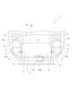
- FIG. 2 is a plan view showing a part of the front structure of the vehicle.
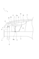
- FIG. 2 is a side view showing a portion of the front structure of the vehicle.
- FIG. FIG. FIG. 1 is a side view conceptually showing a state in which a flank is deformed when an impact is applied from the front.
- FIG. 1 is a plan view conceptually showing a state in which a flank is deformed when an impact is applied from the front.
- 11 is a cross-sectional view showing a state in which items stored in the frunk are guided to the rear portion and moved upward when an impact is applied from the front.
- FIG. 1 is a perspective view showing a part of the front structure of the vehicle.
- FIG. 2 is a plan view showing a part of the front structure of the vehicle.
- Vehicle 100 is, for example, an electric vehicle that runs only on electrical power, and is equipped with a drive motor 110, an accelerator opening sensor 120, a speed sensor 130, and a control unit 140.
- vehicle 100 may also be a hybrid vehicle that runs on at least one of fuel (gasoline) power and electrical power, or a vehicle that runs only on fuel power.
- the drive motor 110 is housed in the space at the front of the passenger compartment and is used as the power source for the vehicle 100. If the vehicle 100 is a hybrid vehicle, two driving modes are set: a hybrid driving mode powered by both the engine and drive motor 110, and a motor driving mode powered only by the drive motor 110, and the two driving modes are switched depending on the driving conditions, etc. If the vehicle 100 is a vehicle that runs only on fuel power, the engine is used as the power source for the vehicle 100.
- the control unit 140 has the function of comprehensively controlling the operation of each part in the vehicle 100 and performing various calculation processes.
- the control unit 140 has a microprocessor 141 that performs calculations, a ROM (Read Only Memory) 142 that stores programs and the like for causing the microprocessor 141 to execute each process, a RAM (Random Access Memory) 143 that stores various data such as the results of calculations, and an interface for inputting or outputting data.
- ROM Read Only Memory
- RAM Random Access Memory
- the control unit 140 includes a motor control unit 144 that controls the drive motor 110.
- the motor control unit 144 has a function of controlling, for example, the drive operation of the wheels of the vehicle 100 by the drive motor 110 and the regenerative operation of the drive motor 110.
- the control unit 140 is provided with an engine control unit that controls the engine, and if the vehicle 100 is a hybrid vehicle, in addition to the engine control unit, a mode switching unit that switches between a driving mode using the drive motor 110 and a driving mode using the engine is also provided.
- the vehicle 100 accommodates a battery 150 in a trunk or the like.
- the battery 150 has a battery module that stores power used in the vehicle 100, such as the power used in the drive motor 110, as well as power used in the control unit 140, various parts of the vehicle 100 that are operated by power, and various lights provided in the vehicle 100.
- the battery module uses secondary batteries such as nickel-metal hydride batteries and lithium-ion batteries.
- the battery 150 stores regenerative power supplied from the drive motor 110, for example.
- the vehicle front structure 1 includes a side frame 2, a bumper beam 3, and a strut tower 4 (see Figures 2 to 4).
- a number of support members 5 extending vertically are provided at a distance from each other on the left and right sides behind the bumper beam 3.
- a lower beam 6 extending horizontally is fastened to the lower ends of the support members 5, and an upper support 7 extending horizontally is fastened to the upper ends of the support members 5.
- the lower beam 6 may be fastened at both the left and right ends to the front portion of the side frame 2, or may be fastened to the front portion of the side frame 2 via other members.
- Upper sides 8 are fastened to both the left and right ends of the upper support 7, and the upper sides 8 are inclined so that they are displaced rearward as they move outward in the left-right direction.
- An upper frame 9 extending in the front-to-rear direction is fastened to the rear end of the upper sides 8.
- a connecting frame 10 extending in the front-to-rear direction is fastened to the rear end of the upper frame 9, and the upper end of the strut tower 4 is fastened to the inner side of the connecting frame 10.
- the vehicle front structure 1 has an accommodation space 11 surrounded by the above-mentioned side frames 2 and other components.
- the accommodation space 11 is the space below the hood (bonnet) 12, and a drive motor 110 is accommodated in the accommodation space 11 at a position below the side frames 2.
- the drive motor 110 is accommodated in the accommodation space 11 at a position toward the rear.
- a radiator (not shown) that functions as a heat exchanger is located at the front end of the storage space 11.
- the radiator is located between the lower beam 6 and the upper support 7, and is held in place by multiple support members 5.
- the radiator is protected by the support members 5, the lower beam 6, and the upper support 7.
- a hood lock 13 is attached to the upper support 7.
- the hood lock 13 has the function of locking the hood 12 in a closed state by engaging with a locking engagement portion (not shown) provided on the hood 12.
- the hood lock 13 has a double locking mechanism and is connected to a release lever (not shown) provided in the vehicle compartment by a hood wire 13a. Therefore, when the release lever is operated, the hood lock 13 is operated via the hood wire 13a, and the first lock state of the hood 12 by the hood lock 13 is released. In addition, when the first lock state is released, the second lock state of the hood 12 by the hood lock 13 is released by inserting a finger into the gap under the hood 12 to operate the hood lock 13, and the hood 12 can be lifted and opened.
- the flank 14 is accommodated in the storage space 11.
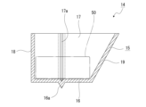
- the flank 14 is accommodated above the drive motor 110 and toward the front end of the storage space 11, and is composed, for example, of only a storage case 15 that opens upward (see Figures 5 and 6).
- the flank 14 may also be configured to have, in addition to the storage case 15, a lid (not shown) that opens and closes the opening of the storage case 15.
- the flank 14 has a rectangular bottom surface portion 16 facing in the vertical direction, a pair of side surfaces 17 connected to both the left and right ends of the bottom surface portion 16, a front surface portion 18 connected to the front end of the bottom surface portion 16, and a rear surface portion 19 connected to the rear end of the bottom surface portion 16, with the rear surface portion 19 inclined downward toward the front. Therefore, the rear surface portion 19 is provided as an inclined portion that displaces upward as it goes rearward.
- a bottom bead 16a is formed in the middle of the bottom portion 16 in the front-to-rear direction.
- the bottom bead 16a is formed in a shape with a V-groove that protrudes downward and opens upward, extends in the left-right direction, and is located between both the left and right ends of the bottom portion 16.
- a side bead 17a is formed in the middle of the side portion 17 in the front-to-rear direction.
- the side bead 17a is formed in a shape having a V-groove that protrudes outward in the left-to-right direction and opens inward in the left-to-right direction, extends in the vertical direction, and is positioned between the upper and lower ends of the side portion 17.
- the front-to-rear position of the side bead 17a on the side portion 17 coincides with the front-to-rear position of the bottom bead 16a on the bottom portion 16. Therefore, the lower ends of the pair of side beads 17a are each continuous with the left and right ends of the bottom side bead 16a.
- the bottom surface 16 of the flank 14 is attached to the pair of side frames 2 by bolts or the like.
- the position P in the fore-and-aft direction of the bottom surface bead 16a and the side surface bead 17a coincides in the fore-and-aft direction with the position T of the fastening point of the upper side 8 and the upper frame 9 (see Figures 3 and 4). Therefore, the position T of the fastening point is located directly to the side of position P.
- the position P of the bottom bead 16a and the side bead 17a in the fore-and-aft direction is aligned with the attachment point S of the flank 14 to the side frame 2.
- the bottom bead 16a makes it easier for the bottom portion 16 to deform into a downward convex shape
- the side bead 17a makes it easier for the side portion 17 to deform into an outward convex shape in the left-right direction. Therefore, even when an item 50 is stored inside the flank 14, the item 50 does not hinder the deformation of the bottom portion 16 and the side portion 17, and as the front portion 18 is crushed and deformed by the impact, the bottom portion 16 is bent and deformed into a downward convex shape by the bottom bead 16a, and the side portion 17 is bent and deformed into an outward convex shape in the left-right direction by the side bead 17a.
- the flank 14 is reliably deformed regardless of the presence or absence of a stored object 50 in the flank 14 or the size and weight of the stored object 50, so a sufficient deformation stroke in the flank 14 is ensured and the rear surface 19 of the flank 14 is unlikely to move rearward. Therefore, the flank 14 is made unlikely to move in a direction approaching the passenger compartment.
- the flank 14 is deformed with a sufficient stroke, a sufficient deformation stroke is ensured in each frame located at the front of the passenger compartment, such as the side frame 2 and upper support 7, and each frame can deform without being hindered by the flank 14.
- the flank 14 is stored in a position above the drive motor 110 and toward the front end of the storage space 11. Even if the flank 14 is moved rearward, the storage position of the flank 14 is located forward away from the passenger compartment, so the impact of the flank 14 on the passenger compartment is minimal.
- the bumper beam 3, lower beam 6, upper support 7, etc. are crushed in the vehicle body, and the upper side 8 and upper frame 9 are bent based on the position T of the fastening point between the upper side 8 and the upper frame 9.
- the position P of the bottom bead 16a and the side bead 17a in the fore-and-aft direction is aligned with the position T of the fastening point between the upper side 8 and the upper frame 9.
- the portion of the vehicle body that is bent coincides with the portion of the flank 14 that is bent, so that the flank 14 is deformed in sync with the deformation of the vehicle body when the vehicle 100 collides, and the behavior during impact absorption is stable, allowing the impact to be absorbed sufficiently.
- the side frame 2 may be crushed in the vehicle body, and a force may be applied to the side frame 2 in a bending direction.
- the position P of the bottom bead 16a and the side bead 17a in the fore-and-aft direction is aligned with the attachment point S of the flank 14 to the side frame 2.
- the rear surface 19 of the flank 14 is inclined downward toward the front, and the rear surface 19 is provided as an inclined portion that displaces upward as it moves rearward.
- flank 14 is less likely to move rearward, further improving safety for passengers.
- a flank 14 is disposed in the storage space 11 and attached to a pair of side frames 2, and a bottom side bead 16a is formed on the bottom portion 16 of the flank 14 for bending the bottom portion 16 into a downwardly convex state when an impact is applied from the front.
- the bottom bead 16a causes the bottom portion 16 to bend in the opposite direction to the side where the stored item 50 stored in the flank 14 is located, so that the flank 14 is deformed with a sufficient stroke regardless of the size or weight of the stored item 50, and the deformation of each frame of the body at the front of the vehicle is less likely to be hindered by the flank 14, so that in the unlikely event of a collision of the vehicle 100, sufficient impact can be absorbed regardless of the stored item 50 stored in the flank 14, improving safety.
- side beads 17a are formed on both the left and right side portions 17 of the flank 14 to bend the side portions 17 outward in the left-right direction in a convex manner when an impact is applied from the front.
- the side bead 17a causes the side portions 17 on both the left and right sides of the flank 14 to bend outwardly in the left-right direction in a convex manner, so that the impact is absorbed by the flank 14 regardless of the shape, size, or weight of the stored item 50 stored in the flank 14, making it difficult for the flank 14 and the stored item 50 to move rearward, thereby further improving safety for passengers.
- the frunk 14 is housed above the drive motor 110, in the unlikely event of a collision of the vehicle 100, the drive motor 110 will not be subjected to impact from the frunk 14, preventing secondary damage such as electric shock, thereby further improving the safety of the vehicle 100.
- flank 14 is accommodated above the drive motor 110 and toward the front end of the accommodation space 11.
- the flank 14 is located close to the operator, which improves the workability and speeds up the process of putting the stored items 50 in and taking them out of the flank 14.
Landscapes
- Engineering & Computer Science (AREA)
- Mechanical Engineering (AREA)
- Chemical & Material Sciences (AREA)
- Combustion & Propulsion (AREA)
- Transportation (AREA)
- Health & Medical Sciences (AREA)
- Epidemiology (AREA)
- General Health & Medical Sciences (AREA)
- Public Health (AREA)
- Body Structure For Vehicles (AREA)
Priority Applications (4)
| Application Number | Priority Date | Filing Date | Title |
|---|---|---|---|
| JP2025521595A JP7787365B2 (ja) | 2023-05-19 | 2023-05-19 | 車両の前部構造 |
| CN202380049583.4A CN119451864A (zh) | 2023-05-19 | 2023-05-19 | 车辆前部结构 |
| PCT/JP2023/018760 WO2024241373A1 (ja) | 2023-05-19 | 2023-05-19 | 車両の前部構造 |
| US18/981,830 US20250115194A1 (en) | 2023-05-19 | 2024-12-16 | Vehicle front structure |
Applications Claiming Priority (1)
| Application Number | Priority Date | Filing Date | Title |
|---|---|---|---|
| PCT/JP2023/018760 WO2024241373A1 (ja) | 2023-05-19 | 2023-05-19 | 車両の前部構造 |
Related Child Applications (1)
| Application Number | Title | Priority Date | Filing Date |
|---|---|---|---|
| US18/981,830 Continuation US20250115194A1 (en) | 2023-05-19 | 2024-12-16 | Vehicle front structure |
Publications (1)
| Publication Number | Publication Date |
|---|---|
| WO2024241373A1 true WO2024241373A1 (ja) | 2024-11-28 |
Family
ID=93588996
Family Applications (1)
| Application Number | Title | Priority Date | Filing Date |
|---|---|---|---|
| PCT/JP2023/018760 Ceased WO2024241373A1 (ja) | 2023-05-19 | 2023-05-19 | 車両の前部構造 |
Country Status (4)
| Country | Link |
|---|---|
| US (1) | US20250115194A1 (https=) |
| JP (1) | JP7787365B2 (https=) |
| CN (1) | CN119451864A (https=) |
| WO (1) | WO2024241373A1 (https=) |
Families Citing this family (1)
| Publication number | Priority date | Publication date | Assignee | Title |
|---|---|---|---|---|
| DE102025113070A1 (de) | 2025-04-03 | 2025-12-11 | Mercedes-Benz Group AG | Struktur zum Verstärken eines Frunks |
Citations (6)
| Publication number | Priority date | Publication date | Assignee | Title |
|---|---|---|---|---|
| KR20070121139A (ko) * | 2006-06-21 | 2007-12-27 | 현대자동차주식회사 | 차량의 스페어 타이어 회전 리프트 구조 |
| JP2016150685A (ja) * | 2015-02-18 | 2016-08-22 | 本田技研工業株式会社 | 車体前部構造 |
| JP2016150726A (ja) * | 2015-02-19 | 2016-08-22 | 富士重工業株式会社 | エネルギ吸収部材の保持構造 |
| JP5992974B2 (ja) * | 2014-09-05 | 2016-09-14 | 本田技研工業株式会社 | 収納ボックス付き車体前部構造 |
| CN109466630A (zh) * | 2017-09-06 | 2019-03-15 | 昶洧新能源汽车发展有限公司 | 作为加强元件的后备箱 |
| JP2021146741A (ja) * | 2020-03-16 | 2021-09-27 | 本田技研工業株式会社 | 車両用収納構造 |
-
2023
- 2023-05-19 WO PCT/JP2023/018760 patent/WO2024241373A1/ja not_active Ceased
- 2023-05-19 JP JP2025521595A patent/JP7787365B2/ja active Active
- 2023-05-19 CN CN202380049583.4A patent/CN119451864A/zh active Pending
-
2024
- 2024-12-16 US US18/981,830 patent/US20250115194A1/en active Pending
Patent Citations (6)
| Publication number | Priority date | Publication date | Assignee | Title |
|---|---|---|---|---|
| KR20070121139A (ko) * | 2006-06-21 | 2007-12-27 | 현대자동차주식회사 | 차량의 스페어 타이어 회전 리프트 구조 |
| JP5992974B2 (ja) * | 2014-09-05 | 2016-09-14 | 本田技研工業株式会社 | 収納ボックス付き車体前部構造 |
| JP2016150685A (ja) * | 2015-02-18 | 2016-08-22 | 本田技研工業株式会社 | 車体前部構造 |
| JP2016150726A (ja) * | 2015-02-19 | 2016-08-22 | 富士重工業株式会社 | エネルギ吸収部材の保持構造 |
| CN109466630A (zh) * | 2017-09-06 | 2019-03-15 | 昶洧新能源汽车发展有限公司 | 作为加强元件的后备箱 |
| JP2021146741A (ja) * | 2020-03-16 | 2021-09-27 | 本田技研工業株式会社 | 車両用収納構造 |
Also Published As
| Publication number | Publication date |
|---|---|
| JP7787365B2 (ja) | 2025-12-16 |
| JPWO2024241373A1 (https=) | 2024-11-28 |
| CN119451864A (zh) | 2025-02-14 |
| US20250115194A1 (en) | 2025-04-10 |
Similar Documents
| Publication | Publication Date | Title |
|---|---|---|
| EP3431371B1 (en) | Vehicle lower portion structure | |
| US11198474B2 (en) | Front vehicle body reinforcing structure | |
| US12208759B2 (en) | Vehicle-body front structure that improves protection for pedestrian collision | |
| JP7785471B2 (ja) | 車両衝突エネルギー吸収システム | |
| CN108215749B (zh) | 电池包的保护结构 | |
| US20250115189A1 (en) | Vehicle front structure | |
| US20250115194A1 (en) | Vehicle front structure | |
| JP7662374B2 (ja) | 車載用バッテリー | |
| WO2024241372A1 (ja) | 車両の前部構造 | |
| JP2020019296A (ja) | 車両後部構造 | |
| JP2932134B2 (ja) | 電気自動車のエネルギ吸収コントロール構造 | |
| US12509154B2 (en) | Inverter mounting structure for vehicle | |
| US20250303969A1 (en) | Vehicle body front structure | |
| JP7726020B2 (ja) | 車体前部構造 | |
| JP2024081059A (ja) | 車両後部バッテリ搭載構造 | |
| WO2026053363A1 (ja) | 車両の前部構造 | |
| EP4159545B1 (en) | Vehicle-body front structure | |
| CN115891884A (zh) | 车体构造 | |
| CN115891886A (zh) | 车体前部构造 | |
| CN115891885A (zh) | 车体前部构造 | |
| WO2025186974A1 (ja) | 車両用電子部品の配置構造 | |
| JP2022143185A (ja) | インパクトビームを有する車両 | |
| JP2022093801A (ja) | 車両用バンパ構造 |
Legal Events
| Date | Code | Title | Description |
|---|---|---|---|
| WWE | Wipo information: entry into national phase |
Ref document number: 202380049583.4 Country of ref document: CN |
|
| 121 | Ep: the epo has been informed by wipo that ep was designated in this application |
Ref document number: 23938350 Country of ref document: EP Kind code of ref document: A1 |
|
| WWP | Wipo information: published in national office |
Ref document number: 202380049583.4 Country of ref document: CN |
|
| WWE | Wipo information: entry into national phase |
Ref document number: 2025521595 Country of ref document: JP |
|
| NENP | Non-entry into the national phase |
Ref country code: DE |