WO2024237205A1 - 払拭装置 - Google Patents
払拭装置 Download PDFInfo
- Publication number
- WO2024237205A1 WO2024237205A1 PCT/JP2024/017446 JP2024017446W WO2024237205A1 WO 2024237205 A1 WO2024237205 A1 WO 2024237205A1 JP 2024017446 W JP2024017446 W JP 2024017446W WO 2024237205 A1 WO2024237205 A1 WO 2024237205A1
- Authority
- WO
- WIPO (PCT)
- Prior art keywords
- pair
- wind pressure
- wiper
- estimated value
- wiping device
- Prior art date
- Legal status (The legal status is an assumption and is not a legal conclusion. Google has not performed a legal analysis and makes no representation as to the accuracy of the status listed.)
- Ceased
Links
Images

Classifications
-
- B—PERFORMING OPERATIONS; TRANSPORTING
- B60—VEHICLES IN GENERAL
- B60S—SERVICING, CLEANING, REPAIRING, SUPPORTING, LIFTING, OR MANOEUVRING OF VEHICLES, NOT OTHERWISE PROVIDED FOR
- B60S1/00—Cleaning of vehicles
- B60S1/02—Cleaning windscreens, windows or optical devices
- B60S1/04—Wipers or the like, e.g. scrapers
- B60S1/06—Wipers or the like, e.g. scrapers characterised by the drive
- B60S1/08—Wipers or the like, e.g. scrapers characterised by the drive electrically driven
- B60S1/0818—Wipers or the like, e.g. scrapers characterised by the drive electrically driven including control systems responsive to external conditions, e.g. by detection of moisture, dirt or the like
- B60S1/0822—Wipers or the like, e.g. scrapers characterised by the drive electrically driven including control systems responsive to external conditions, e.g. by detection of moisture, dirt or the like characterized by the arrangement or type of detection means
-
- B—PERFORMING OPERATIONS; TRANSPORTING
- B60—VEHICLES IN GENERAL
- B60S—SERVICING, CLEANING, REPAIRING, SUPPORTING, LIFTING, OR MANOEUVRING OF VEHICLES, NOT OTHERWISE PROVIDED FOR
- B60S1/00—Cleaning of vehicles
- B60S1/02—Cleaning windscreens, windows or optical devices
- B60S1/04—Wipers or the like, e.g. scrapers
- B60S1/06—Wipers or the like, e.g. scrapers characterised by the drive
- B60S1/08—Wipers or the like, e.g. scrapers characterised by the drive electrically driven
- B60S1/0896—Wipers or the like, e.g. scrapers characterised by the drive electrically driven including control systems responsive to a vehicle driving condition, e.g. speed
Definitions
- the present invention relates to a wiping device.
- Patent Document 1 discloses a window wiping device that evenly wipes the surface by changing the control signal of the motor according to the wind load obtained from the vehicle speed and/or wiping speed.
- the present invention was made in consideration of the above-mentioned circumstances, and aims to provide a wiping device that can reduce the risk of interference between the wiper blade and other components.
- the present invention employs, as a first solution for a wiping device, a wiping device that reciprocates a wiper blade by driving a power source with a predetermined drive signal, and corrects the reversal position of the wiper blade by changing the drive signal according to the wind pressure acting on the wiper blade, and is provided with a drive control unit that obtains a first wind pressure estimate based on the vehicle speed and a second wind pressure estimate based on the drive signal, and corrects the reversal position based on the first wind pressure estimate if the first wind pressure estimate is greater than the second wind pressure estimate, and corrects the reversal position based on the second wind pressure estimate if the first wind pressure estimate is equal to or less than the second wind pressure estimate.
- the present invention employs a second solution relating to a wiping device, which is the same as the first solution described above, except that the drive signal is a PWM (Pulse Width Modulation) signal, and the drive control unit obtains the second wind pressure estimate based on the duty ratio of the PWM signal.
- PWM Pulse Width Modulation
- the present invention adopts a third solution relating to the wiping device, which is the second solution described above, in which the duty ratio is an average value for a predetermined period of the wiper blade's forward or backward movement.
- the present invention adopts a fourth solution related to the wiping device, which is any one of the first to third solutions above, in which one or two power sources are provided, and one or two of the wiper blades are reciprocated by one of the power sources, and two of the power sources are used to reciprocate two of the wiper blades individually.
- the present invention makes it possible to provide a wiping device that can reduce the risk of interference between the wiper blade and other components.
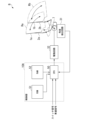
- FIG. 1 is a block diagram showing a functional configuration of a wiping device A according to a first embodiment of the present invention.
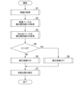
- FIG. 4 is a flowchart showing the operation of the wiping device A according to the first embodiment of the present invention.
- 5 is a characteristic diagram showing a change in a correction standard for a reversal position in the first embodiment of the present invention.
- FIG. 11 is a block diagram showing a functional configuration of a wiping device B according to a second embodiment of the present invention.
- a wiping device A is a device that is mounted on various vehicles such as a gasoline-powered vehicle, a hybrid vehicle, or an electric vehicle, and wipes away rainwater adhering to the surface (wiped surface) of a member to be wiped, such as a windshield or a rear window.
- this wiping device A employs a two-motor drive system in which a pair of wiper blades 1a, 1b are driven individually by a pair of motors 7a, 7b, which serve as power sources.
- the wiping device A according to the first embodiment is provided with two power sources, and the two power sources reciprocate the pair of wiper blades 1a, 1b individually.
- this wiping device A includes a pair of wiper blades 1a, 1b, a pair of wiper arms 2a, 2b, and a pair of motors 7a, 7b.
- a indicates a member or part that is present on or related to the driver's side of the vehicle.
- b indicates a member or part that is present on or related to the passenger's side of the vehicle.
- the pair of wiper blades 1a, 1b are rod-shaped members placed on the windshield W (object to be wiped).
- the pair of wiper blades 1a, 1b abut against the surface of the windshield W (surface to be wiped) and wipe away rainwater adhering to the surface by reciprocating (oscillating) over the surface.
- the symbol Ra indicates the wiping range of the wiper blade 1a on the driver's side
- the symbol Rb indicates the wiping range of the wiper blade 1b on the passenger's side.
- the wiping range Ra on the driver's side is the range of movement of the wiper blade 1a, which extends from the lower inversion position to the upper inversion position and is centered on the wiper shaft 3a on the driver's side.
- the wiping range Rb on the passenger's side is the range of movement of the wiper blade 1b, which extends from the lower inversion position to the upper inversion position and is centered on the wiper shaft 3b on the passenger's side.
- the pair of wiper blades 1a, 1b stop at the lower reversal position and the upper reversal position for a predetermined period during their reciprocating motion in the wiping ranges Ra, Rb. Specifically, when the pair of wiper blades 1a, 1b move from the lower reversal position toward the upper reversal position, they stop at the upper reversal position for a predetermined stop period T, and after this stop period T has elapsed, they move from the upper reversal position toward the lower reversal position.
- the pair of wiper blades 1a, 1b are driven by a pair of motors 7a, 7b to perform reciprocating motion across the wiping ranges Ra, Rb, so the lower and upper reversal positions are set by the pair of motors 7a, 7b.
- the lower and upper reversal positions are corrected according to the vehicle speed (vehicle speed) or the drive signals of the pair of motors that drive the pair of wiper blades 1a, 1b, respectively.
- the pair of wiper blades 1a, 1b are mechanically connected to a pair of motors 7a, 7b via a pair of wiper arms 2a, 2b. That is, the wiper blade 1a on the driver's side is connected to the motor 7a via the wiper arm 2a provided on the driver's side.
- the wiper blade 1b on the passenger's side is connected to the motor 7b via the wiper arm 2b provided on the passenger's side.
- the pair of wiper arms 2a, 2b are rod-shaped members, with one end connected to the middle of the pair of wiper blades 1a, 1b, and the other end connected to the pair of wiper shafts 3a, 3b. That is, the wiper arm 2a on the driver's seat side has one end connected to the middle of the wiper blade 1a on the driver's seat side, and the other end connected to the wiper shaft 3a on the driver's seat side.
- one end of the passenger side wiper arm 2b is connected to the middle of the passenger side wiper blade 1b, and the other end is connected to the passenger side wiper shaft 3b.
- This pair of wiper arms 2a, 2b are members included in the components of the pair of wiper blades 1a, 1b.
- the pair of wiper arms 2a, 2b function as power transmission components that mechanically transmit the rotational force of the pair of motors 7a, 7b to the pair of wiper blades 1a, 1b.
- the pair of wiper arms 2a, 2b also function as biasing members that press the pair of wiper blades 1a, 1b against the surface (wiped surface) of the windshield W with a predetermined pressing force.
- the pair of motors 7a, 7b are power generating devices that reciprocate the pair of wiper blades 1a, 1b via the pair of wiper arms 2a, 2b.
- the pair of wiper shafts 3a, 3b which are respectively provided on the pair of motors 7a, 7b, are rotated within a predetermined angle range to reciprocate the pair of wiper blades 1a, 1b placed on the surface of the windshield W (the surface to be wiped).
- the pair of motors 7a, 7b serve as power sources corresponding to the pair of wiper shafts (output shafts) 3a, 3b.
- Each of the pair of motors 7a, 7b has a motor body 8 and a reduction mechanism 9.
- the pair of motors 7a, 7b (power sources) has wiper control units 10a, 10b built into each reduction mechanism 9.
- the pair of wiper control units 10a, 10b are drive control units that control the pair of motors 7a, 7b (power sources).
- the driver's side wiper control unit 10a controls the driver's side motor 7a to cause the driver's side wiper blade 1a to reciprocate on the surface to be wiped.
- the passenger side wiper control unit 10b controls the passenger side motor 7b to cause the passenger side wiper blade 1b to reciprocate on the surface to be wiped.
- the driver's side wiper control unit 10a includes a CPU (Central Processing Unit) 21a, a communication circuit 22a, a ROM (Read Only Memory) 23a, a RAM (Random Access Memory) 24a, an angle detection circuit 31a, a drive circuit 32a, and a lock detection timer 33a.
- the passenger's side wiper control unit 10b includes a CPU 21b, a communication circuit 22b, a ROM 23b, a RAM 24b, an angle detection circuit 31b, a drive circuit 32b, and a lock detection timer 33b.
- the wiper control unit 10a on the driver's side and the wiper control unit 10b on the passenger's side are connected to each other for free communication via a pair of communication circuits 22a, 22b.
- One of the wiper control units 10a is also connected to the ECU, which is the vehicle's higher-level control device, via a communication line.
- This wiper control unit 10a receives switch signals from the ECU, such as ON/OFF (Lo operation, Hi operation, INT operation) of the wiper switch and ON/OFF of the mist switch that sprays washer fluid, as well as a vehicle speed signal indicating the vehicle speed V.
- the movement positions of the pair of wiper blades 1a, 1b are set by feedback controlling the pair of motors 7a, 7b based on the elapsed time of movement from an absolute position that serves as a reference for control.
- this position control for example, the lower reversal position is used as the absolute position.
- the target rotation speed TR of the pair of motors 7a, 7b at each point in time is preset as an operation map corresponding to the elapsed time t of movement from the lower reversal position (reference position).
- the pair of wiper control units 10a, 10b measure the elapsed time t from the lower reversal position (reference position) in the pair of CPUs 21a, 21b, grasp the current rotation speed of the pair of motors 7a, 7b, and compare the current rotation speed at the elapsed time t with the target rotation speed TR on the operation map.
- the pair of CPUs 21a, 21b feedback-control the pair of drive circuits 32a, 32b according to the difference between the current rotation speed and the target rotation speed TR, thereby generating a pair of PWM (Pulse Width Modulation) drive signals that drive and control the pair of motors 7a, 7b.
- PWM Pulse Width Modulation
- the upper reversal position of the pair of wiper blades 1a, 1b is set based on a pair of control command values output from the pair of CPUs 21a, 21b to the pair of drive circuits 32a, 32b, respectively, based on the difference between the current rotation speed and the target rotation speed TR.
- the pair of drive circuits 32a, 32b set the upper reversal position to a predetermined position by generating a pair of PWM drive signals that drive the pair of motors 7a, 7b based on the pair of control command values.
- a pair of angle detection circuits 31a, 31b that detect the positions of the pair of wiper blades 1a, 1b are provided between the pair of motors 7a, 7b and the pair of CPUs 21a, 21b.
- the pair of angle detection circuits 31a, 31b output relative position signals that are proportional to the rotation angles of the pair of motors 7a, 7b and indicate the amount of movement of the pair of wiper blades 1a, 1b to the pair of CPUs 21a, 21b.
- the driver's seat side angle detection circuit 31a is provided between the driver's seat side motor 7a and the driver's seat side CPU 21a.
- This angle detection circuit 31a outputs a relative position signal to the CPU 21a that is proportional to the rotation angle of the driver's seat side motor 7a and indicates the amount of movement of the driver's seat side wiper blade 1a.
- This angle detection circuit 31a also outputs an absolute position signal to the CPU 21a that indicates the position of the driver's seat side wiper blade 1a.
- the passenger side angle detection circuit 31b is provided between the passenger side motor 7b and the passenger side CPU 21b.
- This angle detection circuit 31b outputs a relative position signal to the CPU 21b that is proportional to the rotation angle of the passenger side motor 7b and indicates the amount of movement of the passenger side wiper blade 1b.
- This angle detection circuit 31b also outputs an absolute position signal to the CPU 21b that indicates the position of the passenger side wiper blade.
- the above-mentioned relative position signal is a pulse signal (motor pulse) output from each of the pair of motors 7a, 7b as the pair of motors 7a, 7b rotate.
- This relative position signal is a pulse signal proportional to the rotation angle of the pair of motors 7a, 7b.
- the absolute position signal is a single pulse signal output from the pair of motors 7a, 7b when the pair of wiper blades 1a, 1b reach the lower reversal position (reference position).
- the rotation speed of the pair of motors 7a, 7b and the rotation speed of the pair of wiper shafts 3a, 3b have a fixed relationship based on the reduction ratio of the reduction mechanism 9.
- the rotation angle of the pair of wiper shafts 3a, 3b is obtained by calculations by the pair of CPUs 21a, 21b based on the number of pulses of the relative position signal.
- the rotation angle of the pair of wiper shafts 3a, 3b and the movement angle of the pair of wiper blades 1a, 1b have a fixed relationship based on the reduction ratio.
- the pair of CPUs 21a, 21b detect the movement angle of the pair of wiper blades 1a, 1b by integrating the number of pulses of the relative position signal.
- the pair of CPUs 21a, 21b obtain the current positions of the pair of wiper blades 1a, 1b based on the integration result of the number of pulses of the relative position signal and the absolute position signal.
- the pair of CPUs 21a, 21b also detect the current rotation speed of the pair of motors 7a, 7b by counting the relative position signal (motor pulses).
- the pair of CPUs 21a, 21b also use a built-in timer to measure the elapsed time t from the time the absolute position signal was acquired.
- the pair of CPUs 21a, 21b also acquire the target positions of the pair of wiper blades 1a, 1b and the target rotation speed TR of the pair of motors 7a, 7b at the current elapsed time from ROMs 23a, 23b.
- the pair of CPUs 21a, 21b compare the current positions of the pair of wiper blades 1a, 1b with the target positions, and grasp the current status of the pair of wiper blades 1a, 1b (advance or delay relative to the target position).
- the pair of CPUs 21a, 21b also calculate the rotation speeds of the pair of motors 7a, 7b based on the status of the rotation speeds of the pair of motors 7a, 7b (high or low relative to the target rotation speed TR), and control the rotation of the pair of motors 7a, 7b based on the calculated rotation speeds.
- the pair of ROMs 23a, 23b prestore the positions of the pair of wiper blades 1a, 1b and the target values of the rotation speeds of the pair of motors 7a, 7b as an operation map, with the elapsed time t from the time the absolute position signal was acquired as a parameter.
- the pair of CPUs 21a, 21b feedback-control the pair of motors 7a, 7b by comparing the target value of the rotation speed in this operation map with the current value.
- the precedence relationship of the pair of wiper blades 1a, 1b is preset. Furthermore, in each operation map, the target rotation speed TR is determined according to the position of the other wiper blade, based on the elapsed time t from the time the absolute position signal was acquired and the current positions of the pair of wiper blades 1a, 1b. For example, even if the elapsed time t and the current positions of the pair of wiper blades 1a, 1b are the same, the target rotation speed TR is set to be large if the other wiper blade's current position is closer to the wiper blade itself, and is set to be small if the other wiper blade's current position is farther away than the wiper blade itself.
- the current positions of the pair of wiper blades 1a, 1b are exchanged between the pair of CPUs 21a, 21b via the pair of communication circuits 22a, 22b, and written to the pair of RAMs 24a, 24b, respectively.
- the pair of CPUs 21a, 21b synchronously control the pair of drive circuits 32a, 32b based on the positional relationship of the pair of wiper blades 1a, 1b written to the pair of RAMs 24a, 24b, thereby generating a pair of PWM drive signals that drive the pair of motors 7a, 7b.
- the external forces acting on the pair of wiper blades 1a, 1b include wind pressure acting on the pair of wiper blades 1a, 1b.
- This wind pressure is a disturbance in the position control of the pair of wiper blades 1a, 1b by the pair of motors 7a, 7b.
- This wind pressure is a physical quantity that has a certain correlation with the vehicle speed (vehicle speed), and can be estimated (predicted) based on the vehicle speed. In addition, this wind pressure can be estimated (predicted) based on the drive current of a pair of motors 7a, 7b, which are the power sources for a pair of wiper blades 1a, 1b.
- the drive current of the pair of motors 7a, 7b is based on the duty ratio of the PWM drive signal supplied to the pair of motors 7a, 7b. Therefore, the above wind pressure can be estimated (predicted) based on the duty ratio of the PWM drive signal.
- the pair of CPUs 21a, 21b which will be described in detail later, acquire a wind pressure estimate E1 (first wind pressure estimate) based on the vehicle speed and acquire a wind pressure estimate E2 (second wind pressure estimate) based on the duty ratio of the PWM drive signal in order to suppress fluctuations in the upper turning position caused by the wind pressure.
- the pair of CPUs 21a, 21b also stabilize fluctuations in the upper turning position by correcting the target rotation speed TR based on the wind pressure estimate E1 or the wind pressure estimate E2.
- the characteristic operation of the wiping device A according to the first embodiment that is, the correction process of the target rotation speed TR based on the vehicle speed and the duty ratio of the PWM drive signal, will be described with reference to the flowchart shown in FIG.
- the pair of CPUs 21a, 21b acquire the vehicle speed by acquiring a switch signal and a vehicle speed signal at a predetermined timing through communication with a higher-level control device (ECU) (step S1).
- the pair of CPUs 21a, 21b then perform a predetermined calculation process on the vehicle speed to obtain an estimated wind pressure E1 acting on the pair of wiper blades 1a, 1b due to the vehicle speed (step S2).
- the pair of CPUs 21a, 21b perform a predetermined calculation process on the duty ratio of the PWM drive signal generated by the pair of drive circuits 32a, 32b to obtain an estimated wind pressure E2 that is caused by the duty ratio and acts on the pair of wiper blades 1a, 1b (step S3).
- the duty ratio of the PWM drive signal is set by a control command that the pair of CPUs 21a, 21b output to the pair of drive circuits 32a, 32b.
- this control command specifies the duty ratio of the PWM drive signal for the pair of drive circuits 32a, 32b. Therefore, the pair of CPUs 21a, 21b calculates the wind pressure estimate value E2 based on the control command that they have acquired, i.e., the duty ratio of the PWM drive signal.
- wind pressure estimated value E2 is calculated based on the average value of the duty ratios of the pair of wiper blades 1a, 1b during a predetermined period of time on the forward or return path. That is, the pair of CPUs 21a, 21b calculates the average value of the duty ratios over a predetermined period by performing an averaging process on multiple time-series duty ratios (control commands) generated at predetermined time intervals, and calculates the wind pressure estimated value E2 using this average value.
- step S4 the pair of CPUs 21a and 21b determine whether the wind pressure estimated value E1 is greater than the wind pressure estimated value E2.
- step S6 set the wind pressure estimated value E1 to the correction coefficient H.
- the pair of CPUs 21a, 21b set the correction coefficient H based on the magnitude relationship between the wind pressure estimated value E1 and the wind pressure estimated value E2.
- the pair of CPUs 21a, 21b correct the target rotation speed TR of the operation map obtained from the pair of ROMs 23a, 23b by using the correction coefficient H set by the above process. That is, the target rotation speed TR of the pair of wiper blades 1a, 1b is corrected based on the larger of the wind pressure estimated value E1 and the wind pressure estimated value E2 (step S7).
- the wiping device A reciprocates the pair of wiper blades 1a, 1b by driving the pair of motors 7a, 7b (power sources) with a PWM drive signal (predetermined drive signal), and corrects the upper reversal position of the pair of wiper blades 1a, 1b by changing the PWM drive signal in response to the external force acting on the pair of wiper blades 1a, 1b.
- a PWM drive signal predetermined drive signal
- the wiping device A also includes a pair of wiper control units 10a, 10b (drive control units) that acquire a wind pressure estimate E1 (first wind pressure estimate) based on the vehicle speed and a wind pressure estimate E2 (second wind pressure estimate) based on the PWM drive signal, and corrects the upper inversion positions of the pair of wiper blades 1a, 1b based on the wind pressure estimate E1 when the wind pressure estimate E1 is greater than the wind pressure estimate E2, and corrects the upper inversion positions of the pair of wiper blades 1a, 1b based on the wind pressure estimate E2 when the wind pressure estimate E1 is equal to or less than the wind pressure estimate E2.
- a pair of wiper control units 10a, 10b drive control units
- the larger of the wind pressure estimated value E1 and the wind pressure estimated value E2 is set as the correction coefficient H to correct the upper reversal position of the pair of wiper blades 1a, 1b. Therefore, according to the first embodiment, it is possible to provide a wiping device A that can stabilize the fluctuation of the reversal position and thereby reduce the risk of interference between the pair of wiper blades 1a, 1b and other components (e.g., vehicle pillars).
- Figure 3(a) shows the initial settings of the wind pressure estimated value E1 and the wind pressure estimated position value E2', which depend on the vehicle speed.
- the dotted line is the wind pressure estimated value E1 based on the vehicle speed signal
- the solid line is the wind pressure estimated initial value E2' based on the duty ratio of the PWM drive signal.
- the wind pressure estimated value E1 (dotted line) is set to a value larger than the wind pressure estimated initial value E2' (solid line).
- FIG. 3(b) shows the wind pressure estimated value E1 and the wind pressure estimated value E2 when a tailwind disturbance acts on the pair of wiper blades 1a, 1b.
- the duty ratio-based wind pressure estimated value E2 is greater than the vehicle speed signal-based wind pressure estimated value E1 because a tailwind acts on the pair of wiper blades 1a, 1b.
- the duty ratio-based wind pressure estimated value E2 is set as the correction coefficient H, and the upper reversal position of the pair of wiper blades 1a, 1b is corrected.
- FIG. 3(c) shows the wind pressure estimated value E1 and the wind pressure estimated value E2 when a disturbance due to a headwind acts on the pair of wiper blades 1a, 1b.
- the duty ratio-based wind pressure estimated value E2 is smaller than the initial wind pressure estimated value E2' because a headwind acts on the pair of wiper blades 1a, 1b.
- the vehicle speed signal-based wind pressure estimated value E1 is set as the correction coefficient H, and the upper reversal position of the pair of wiper blades 1a, 1b is corrected.
- the wiping device B includes a pair of wiper blades 1a and 1b, a pair of wiper arms 2a and 2b, a link mechanism 4, a motor 7, an angle detection circuit 31, a drive circuit 32, and a wiper control unit 10A.
- the wiper control unit 10A also includes a CPU 50, a ROM 51, and a RAM 52.
- This wiping device B employs a single motor drive system in which a pair of wiper blades 1a, 1b are driven by a single motor 7 (power source) by mechanically connecting a pair of wiper arms 2a, 2b with a link mechanism 4.
- wiping device B is provided with one power source, which reciprocates the pair of wiper blades 1a, 1b.
- This wiping device B wipes rainwater off the surface (wiped surface) of the vehicle's windshield or rear windshield, just like wiping device A of the first embodiment.
- the link mechanism 4 is a mechanical component that is mechanically connected to the other ends of the pair of wiper arms 2a, 2b and also connected to the output shaft of the motor 7.
- the link mechanism 4 also has a support shaft fixed to the vehicle and is freely rotatable around the support shaft.
- the output shaft of the motor 7 is connected to the link mechanism 4, and by manipulating the rotation angle of the link mechanism 4, the pair of wiper blades 1a, 1b are caused to reciprocate on the surface to be wiped.
- the angle detection circuit 31 has the same functions as the pair of angle detection circuits 31a, 31b in the first embodiment, and outputs a relative position signal that is proportional to the motor rotation angle of the motor 7 and indicates the amount of movement of the driver's side wiper blade 1a or the passenger side wiper blade 1b. In addition, this angle detection circuit 31 outputs an absolute position signal that indicates the position of a specific wiper blade of the pair of wiper blades 1a, 1b.
- the drive circuit 32 has the same functions as the drive circuits 32a and 32b in the first embodiment, and drives the motor 7 based on a control command input from the CPU 50. That is, the drive circuit 32 drives the motor 7 according to the difference between the current rotation speed of the motor 7 and the target rotation speed TR.
- the wiper control unit 10A has the same functions as the wiper control unit 10a in the first embodiment. Furthermore, this wiper control unit 10A directly controls the drive circuit 32 by referring to the switch signal and vehicle speed signal input from a higher-level control device, thereby indirectly feedback-controlling the motor 7.
- the CPU 50 has the same functions as the CPU 21a in the first embodiment.
- the wiper control unit 10A, the angle detection circuit 31, and the drive circuit 32 may be built into the motor 7.
- This CPU 50 controls the drive circuit 32 based on the operation map stored in ROM 23a, the relative position signal and absolute position signal input from the angle detection circuit 31, and the switch signal and vehicle speed signal input from the higher-level control system.
- the ROM 51 also has the same functions as the ROM 23a in the first embodiment, and stores the operation map and the like.
- the RAM 52 temporarily holds intermediate data generated by the CPU 50.
- the CPU 50 acquires the vehicle speed by acquiring a switch signal and a vehicle speed signal at a predetermined timing through communication with a higher-level control device (ECU). The CPU 50 then performs a predetermined calculation process on the vehicle speed to obtain an estimated wind pressure E1 that is caused by the vehicle speed and acts on the pair of wiper blades 1a, 1b.
- ECU higher-level control device
- the CPU 50 performs a predetermined calculation process on the duty ratio of the PWM drive signal generated by the drive circuit 32 to obtain an estimated wind pressure E2, which is an estimate of the wind pressure acting on the pair of wiper blades 1a, 1b due to the duty ratio.
- the CPU 50 acquires the wind pressure estimated value E1 and the wind pressure estimated value E2 in this manner, it evaluates the magnitude relationship between the wind pressure estimated value E1 and the wind pressure estimated value E2. That is, the CPU 50 determines whether the wind pressure estimated value E1 is greater than the wind pressure estimated value E2, and if the determination is "No", it sets the wind pressure estimated value E2 to the correction coefficient H.
- the CPU 50 sets the wind pressure estimated value E1 as the correction coefficient H. That is, the CPU 50 sets the correction coefficient H based on the magnitude relationship between the wind pressure estimated value E1 and the wind pressure estimated value E2. Then, the CPU 50 corrects the target rotation speed TR of the operation map obtained from the ROM 51 by using the correction coefficient H set by the above process. That is, the target rotation speed TR of the pair of wiper blades 1a, 1b is corrected based on the larger wind pressure estimated value of the wind pressure estimated value E1 and the wind pressure estimated value E2.
- the wiping device B reciprocates the pair of wiper blades 1a, 1b by driving the motor 7 (power source) with a PWM drive signal (predetermined drive signal), and corrects the upper reversal position of the pair of wiper blades 1a, 1b by changing the PWM drive signal in response to the external force acting on the pair of wiper blades 1a, 1b.
- a PWM drive signal predetermined drive signal
- the wiping device B also includes a wiper control unit 10A (drive control unit) that acquires a wind pressure estimate E1 (first wind pressure estimate) based on the vehicle speed and a wind pressure estimate E2 (second wind pressure estimate) based on the PWM drive signal, and corrects the upper inversion positions of the pair of wiper blades 1a, 1b based on the wind pressure estimate E1 if the wind pressure estimate E1 is greater than the wind pressure estimate E2, and corrects the upper inversion positions of the pair of wiper blades 1a, 1b based on the wind pressure estimate E2 if the wind pressure estimate E1 is equal to or less than the wind pressure estimate E2.
- a wiper control unit 10A drive control unit
- the larger of the wind pressure estimated value E1 and the wind pressure estimated value E2 is set as the correction coefficient H to correct the upper reversal position of the pair of wiper blades 1a, 1b. Therefore, according to the second embodiment, it is possible to provide a wiping device B that can stabilize the fluctuation of the upper reversal position and thereby reduce the risk of interference between the pair of wiper blades 1a, 1b and other components (e.g., vehicle pillars).
- the risk of interference with other components is reduced by stabilizing the upper reversal position
- the present invention is not limited to this.
- the reference position of a pair of wiper blades 1a, 1b is in the upper reversal position, it is possible to stabilize fluctuations in the lower reversal position by setting the correction coefficient H based on the wind pressure estimates E1 and E2.
- a drive control unit that drives the power source by adjusting the drive current according to the duty ratio of the PWM drive signal has been described, but the present invention is not limited to this.
- a drive control unit that generates a drive signal that drives the power source by adjusting the dynamic current according to the amplitude may be used.
- the wind pressure estimate E2 is estimated based on the amplitude of the drive signal.
Landscapes
- Engineering & Computer Science (AREA)
- Mechanical Engineering (AREA)
- Automation & Control Theory (AREA)
- Control Of Multiple Motors (AREA)
- Control Of Direct Current Motors (AREA)
Abstract
Description
図1~図3を参照して本発明の第1実施形態について説明する。第1実施形態に係る払拭装置Aは、ガソリン自動車、ハイブリッド自動車又は電気自動車等、各種の車両に搭載され、フロントガラスやリヤガラス等の被払拭部材の表面(被払拭面)に付着する雨水を払拭する装置である。
次に、本発明の第2実施形態について、図4を参照して説明する。なお、この第2実施形態では、第1実施形態と同一な構成要素には同一符号を付している。
Claims (4)
- 所定の駆動信号によって動力源を駆動することによってワイパブレードを往復運動させるとともに、前記ワイパブレードに作用する風圧に応じて前記駆動信号を変化させることにより前記ワイパブレードの反転位置を補正する払拭装置であって、
車速に基づく第1の風圧推定値と前記駆動信号に基づく第2の風圧推定値と、を取得し、前記第1の風圧推定値が前記第2の風圧推定値よりも大きい場合は、前記第1の風圧推定値に基づいて前記反転位置を補正し、前記第1の風圧推定値が前記第2の風圧推定値以下の場合には、前記第2の風圧推定値に基づいて前記反転位置を補正する駆動制御部を備えることを特徴とする払拭装置。 - 前記駆動信号は、PWM(Pulse Width Modulation)信号であり、
前記駆動制御部は、前記PWM信号のデューティ比に基づいて前記第2の風圧推定値を取得することを特徴とする請求項1に記載の払拭装置。 - 前記デューティ比は、前記ワイパブレードの往路又は復路の所定期間における平均値であることを特徴とする請求項2に記載の払拭装置。
- 前記動力源は、1つ又は2つ設けられており、1つの前記動力源で1又は2つの前記ワイパブレードを往復運動させ、2つの前記動力源で2つの前記ワイパブレードを個別に往復運動させることを特徴とする請求項1~3のいずれか一項に記載の払拭装置。
Priority Applications (3)
| Application Number | Priority Date | Filing Date | Title |
|---|---|---|---|
| DE112024002082.8T DE112024002082T5 (de) | 2023-05-15 | 2024-05-10 | Wischvorrichtung |
| CN202480004488.7A CN120076959A (zh) | 2023-05-15 | 2024-05-10 | 刮拭装置 |
| US19/122,238 US20260152148A1 (en) | 2023-05-15 | 2024-05-10 | Wiping device |
Applications Claiming Priority (2)
| Application Number | Priority Date | Filing Date | Title |
|---|---|---|---|
| JP2023080067 | 2023-05-15 | ||
| JP2023-080067 | 2023-05-15 |
Publications (1)
| Publication Number | Publication Date |
|---|---|
| WO2024237205A1 true WO2024237205A1 (ja) | 2024-11-21 |
Family
ID=93519706
Family Applications (1)
| Application Number | Title | Priority Date | Filing Date |
|---|---|---|---|
| PCT/JP2024/017446 Ceased WO2024237205A1 (ja) | 2023-05-15 | 2024-05-10 | 払拭装置 |
Country Status (4)
| Country | Link |
|---|---|
| US (1) | US20260152148A1 (ja) |
| CN (1) | CN120076959A (ja) |
| DE (1) | DE112024002082T5 (ja) |
| WO (1) | WO2024237205A1 (ja) |
Citations (8)
| Publication number | Priority date | Publication date | Assignee | Title |
|---|---|---|---|---|
| JP2002264776A (ja) * | 2001-03-14 | 2002-09-18 | Mitsuba Corp | ワイパ装置の制御方法 |
| JP2003252179A (ja) * | 2002-03-04 | 2003-09-10 | Mitsuba Corp | ワイパ装置 |
| JP2008006971A (ja) * | 2006-06-29 | 2008-01-17 | Asmo Co Ltd | 車両用ワイパウォッシャ制御装置及び車両用ワイパウォッシャ装置 |
| JP2009029216A (ja) * | 2007-07-25 | 2009-02-12 | Mitsuba Corp | ワイパ装置制御方法及びワイパ制御装置 |
| JP2010159044A (ja) * | 2008-12-09 | 2010-07-22 | Asmo Co Ltd | ワイパ装置及びワイパ制御方法 |
| JP2011131778A (ja) * | 2009-12-25 | 2011-07-07 | Mitsuba Corp | ワイパ制御装置及びワイパ制御方法 |
| JP2014237418A (ja) * | 2013-06-10 | 2014-12-18 | トヨタ自動車株式会社 | ワイパ装置 |
| WO2022145126A1 (ja) * | 2020-12-28 | 2022-07-07 | 株式会社ミツバ | ワイパ制御方法及びワイパ制御装置 |
-
2024
- 2024-05-10 CN CN202480004488.7A patent/CN120076959A/zh active Pending
- 2024-05-10 WO PCT/JP2024/017446 patent/WO2024237205A1/ja not_active Ceased
- 2024-05-10 DE DE112024002082.8T patent/DE112024002082T5/de active Pending
- 2024-05-10 US US19/122,238 patent/US20260152148A1/en active Pending
Patent Citations (8)
| Publication number | Priority date | Publication date | Assignee | Title |
|---|---|---|---|---|
| JP2002264776A (ja) * | 2001-03-14 | 2002-09-18 | Mitsuba Corp | ワイパ装置の制御方法 |
| JP2003252179A (ja) * | 2002-03-04 | 2003-09-10 | Mitsuba Corp | ワイパ装置 |
| JP2008006971A (ja) * | 2006-06-29 | 2008-01-17 | Asmo Co Ltd | 車両用ワイパウォッシャ制御装置及び車両用ワイパウォッシャ装置 |
| JP2009029216A (ja) * | 2007-07-25 | 2009-02-12 | Mitsuba Corp | ワイパ装置制御方法及びワイパ制御装置 |
| JP2010159044A (ja) * | 2008-12-09 | 2010-07-22 | Asmo Co Ltd | ワイパ装置及びワイパ制御方法 |
| JP2011131778A (ja) * | 2009-12-25 | 2011-07-07 | Mitsuba Corp | ワイパ制御装置及びワイパ制御方法 |
| JP2014237418A (ja) * | 2013-06-10 | 2014-12-18 | トヨタ自動車株式会社 | ワイパ装置 |
| WO2022145126A1 (ja) * | 2020-12-28 | 2022-07-07 | 株式会社ミツバ | ワイパ制御方法及びワイパ制御装置 |
Also Published As
| Publication number | Publication date |
|---|---|
| CN120076959A (zh) | 2025-05-30 |
| US20260152148A1 (en) | 2026-06-04 |
| DE112024002082T5 (de) | 2026-02-26 |
Similar Documents
| Publication | Publication Date | Title |
|---|---|---|
| US10017159B2 (en) | Wiper control method and wiper control device | |
| US8405336B2 (en) | Wiper system and wiper control method | |
| US7895701B2 (en) | Opposite-type wiper apparatus | |
| JP2000255384A (ja) | ワイパ制御装置 | |
| CN106132787A (zh) | 雨刷器系统控制方法以及雨刷器系统控制装置 | |
| JP5184395B2 (ja) | ワイパ制御方法及びワイパ制御装置 | |
| US9660566B2 (en) | Motor control method and motor control device | |
| JP5180542B2 (ja) | ワイパ装置 | |
| JP2008238899A (ja) | ワイパ装置制御方法及びワイパ制御装置 | |
| US10723320B2 (en) | Wiper control device | |
| JP7462551B2 (ja) | ワイパ制御方法及びワイパ制御装置 | |
| JP5952710B2 (ja) | ワイパ制御装置及びワイパ制御方法 | |
| JP2009029216A (ja) | ワイパ装置制御方法及びワイパ制御装置 | |
| JP7060481B2 (ja) | ワイパ装置 | |
| JP2024134084A (ja) | 払拭装置 | |
| CN120076959A (zh) | 刮拭装置 | |
| JP7236876B2 (ja) | ワイパ装置及びワイパ制御装置 | |
| JP2024134013A (ja) | 払拭装置 | |
| JP2025186940A (ja) | 払拭装置 | |
| JP2025066436A (ja) | 払拭装置 | |
| WO2025154630A1 (ja) | 払拭装置 | |
| JP2025065755A (ja) | 払拭装置 | |
| JP2009077516A (ja) | モータの回転速度算出方法及びワイパ装置 | |
| JP3910297B2 (ja) | 対向払拭型ワイパ装置の制御方法および制御装置 | |
| WO2025150463A1 (ja) | 払拭装置 |
Legal Events
| Date | Code | Title | Description |
|---|---|---|---|
| 121 | Ep: the epo has been informed by wipo that ep was designated in this application |
Ref document number: 24807157 Country of ref document: EP Kind code of ref document: A1 |
|
| WWE | Wipo information: entry into national phase |
Ref document number: 202480004488.7 Country of ref document: CN |
|
| WWP | Wipo information: published in national office |
Ref document number: 202480004488.7 Country of ref document: CN |
|
| WWE | Wipo information: entry into national phase |
Ref document number: 112024002082 Country of ref document: DE |
|
| WWP | Wipo information: published in national office |
Ref document number: 112024002082 Country of ref document: DE |
|
| 122 | Ep: pct application non-entry in european phase |
Ref document number: 24807157 Country of ref document: EP Kind code of ref document: A1 |