WO2024237173A1 - インクジェットプリンタの調整方法、プログラム、及び印刷システム - Google Patents
インクジェットプリンタの調整方法、プログラム、及び印刷システム Download PDFInfo
- Publication number
- WO2024237173A1 WO2024237173A1 PCT/JP2024/017329 JP2024017329W WO2024237173A1 WO 2024237173 A1 WO2024237173 A1 WO 2024237173A1 JP 2024017329 W JP2024017329 W JP 2024017329W WO 2024237173 A1 WO2024237173 A1 WO 2024237173A1
- Authority
- WO
- WIPO (PCT)
- Prior art keywords
- pattern
- head
- inkjet
- adjustment
- main scanning
- Prior art date
- Legal status (The legal status is an assumption and is not a legal conclusion. Google has not performed a legal analysis and makes no representation as to the accuracy of the status listed.)
- Ceased
Links
Images




Classifications
-
- B—PERFORMING OPERATIONS; TRANSPORTING
- B41—PRINTING; LINING MACHINES; TYPEWRITERS; STAMPS
- B41J—TYPEWRITERS; SELECTIVE PRINTING MECHANISMS, i.e. MECHANISMS PRINTING OTHERWISE THAN FROM A FORME; CORRECTION OF TYPOGRAPHICAL ERRORS
- B41J2/00—Typewriters or selective printing mechanisms characterised by the printing or marking process for which they are designed
- B41J2/005—Typewriters or selective printing mechanisms characterised by the printing or marking process for which they are designed characterised by bringing liquid or particles selectively into contact with a printing material
- B41J2/01—Ink jet
- B41J2/21—Ink jet for multi-colour printing
- B41J2/2132—Print quality control characterised by dot disposition, e.g. for reducing white stripes or banding
- B41J2/2135—Alignment of dots
-
- B—PERFORMING OPERATIONS; TRANSPORTING
- B41—PRINTING; LINING MACHINES; TYPEWRITERS; STAMPS
- B41J—TYPEWRITERS; SELECTIVE PRINTING MECHANISMS, i.e. MECHANISMS PRINTING OTHERWISE THAN FROM A FORME; CORRECTION OF TYPOGRAPHICAL ERRORS
- B41J19/00—Character- or line-spacing mechanisms
- B41J19/14—Character- or line-spacing mechanisms with means for effecting line or character spacing in either direction
- B41J19/142—Character- or line-spacing mechanisms with means for effecting line or character spacing in either direction with a reciprocating print head printing in both directions across the paper width
- B41J19/145—Dot misalignment correction
-
- B—PERFORMING OPERATIONS; TRANSPORTING
- B41—PRINTING; LINING MACHINES; TYPEWRITERS; STAMPS
- B41J—TYPEWRITERS; SELECTIVE PRINTING MECHANISMS, i.e. MECHANISMS PRINTING OTHERWISE THAN FROM A FORME; CORRECTION OF TYPOGRAPHICAL ERRORS
- B41J2/00—Typewriters or selective printing mechanisms characterised by the printing or marking process for which they are designed
- B41J2/005—Typewriters or selective printing mechanisms characterised by the printing or marking process for which they are designed characterised by bringing liquid or particles selectively into contact with a printing material
- B41J2/01—Ink jet
- B41J2/21—Ink jet for multi-colour printing
- B41J2/2132—Print quality control characterised by dot disposition, e.g. for reducing white stripes or banding
- B41J2/2146—Print quality control characterised by dot disposition, e.g. for reducing white stripes or banding for line print heads
-
- B—PERFORMING OPERATIONS; TRANSPORTING
- B41—PRINTING; LINING MACHINES; TYPEWRITERS; STAMPS
- B41J—TYPEWRITERS; SELECTIVE PRINTING MECHANISMS, i.e. MECHANISMS PRINTING OTHERWISE THAN FROM A FORME; CORRECTION OF TYPOGRAPHICAL ERRORS
- B41J25/00—Actions or mechanisms not otherwise provided for
- B41J25/304—Bodily-movable mechanisms for print heads or carriages movable towards or from paper surface
- B41J25/308—Bodily-movable mechanisms for print heads or carriages movable towards or from paper surface with print gap adjustment mechanisms
Definitions
- the present invention relates to an adjustment method, program, and printing system for an inkjet printer.
- the volume of ink can be adjusted by changing the voltage of the drive signal supplied to each nozzle of each inkjet head. For example, one possible method would be to measure the volume of ink using a mass meter and then adjust the voltage of the drive signal.
- Inkjet heads usually have many nozzles. Inkjet printers may also use multiple inkjet heads. Adjusting the discharge of multiple nozzles in multiple inkjet heads using conventional methods would require an extremely large amount of time and effort. It is also possible that the results of the adjustments will vary depending on the operator performing the adjustments. For this reason, there has been a demand for easier and more appropriate adjustments to inkjet printers. Therefore, an object of the present invention is to provide an adjustment method, program, and printing system for an inkjet printer that can solve the above problems.
- the inventors of the present application have considered making adjustments to the inkjet head by focusing on the ejection direction speed, which is the speed in the vertical direction from the inkjet head to the medium.
- the inventors of the present application have also noted that, with regard to the ink ejection direction speed, the ink landing position in the direction in which the inkjet head moves (main scanning direction) during main scanning operation of the inkjet head changes depending on the ejection direction speed. They have also considered checking the state of the nozzle by ejecting ink from the inkjet head at multiple different heights and measuring the distance between the landing positions caused by the difference in height. Then, by actually conducting various experiments, they have found that it is possible to check the state of the nozzle using this method, and that the confirmation results can be used to easily and appropriately adjust the inkjet printer.
- the present invention provides an inkjet printer adjustment method for adjusting an inkjet printer, comprising a pattern printing step of causing the inkjet printer to print a predetermined test pattern on a medium, an analysis step of analyzing the results of reading the test pattern printed on the medium, and an adjustment step of making adjustments to reflect the results of the analysis in the analysis step in the operation of the inkjet printer.
- the inkjet printer comprises an inkjet head that ejects ink, a main scanning drive unit that causes the inkjet head to perform a main scanning operation to eject ink while moving in a main scanning direction perpendicular to the vertical direction, and a head position adjustment unit that changes the height of the inkjet head in the vertical direction.
- the head position adjustment unit changes the height of the inkjet head in multiple steps, thereby changing the head gap, which is the distance between the surface of the medium and the nozzle surface at the bottom of the inkjet head, in multiple steps, and causes the inkjet printer to print the test pattern.
- the analysis step the amount of change in the ink landing position in the main scanning direction caused by the difference in the head gap is detected based on the test pattern, and in the adjustment step, adjustments are made based on the amount of change in the landing position.
- the state of the inkjet printer can be properly detected based on the amount of change in the ink landing position in the main scanning direction detected using the test pattern.
- appropriate adjustments can be made to the inkjet printer based on the detection results.
- the test pattern is an example of a pattern in which ink is ejected from the inkjet head from different heights.
- the head position adjustment unit changes the height of the inkjet head between at least one of the multiple main scanning operations performed to print the test pattern, thereby making the height of the inkjet head different when the main scanning operations before and after that are performed.
- the inkjet printer adjustment method may further include a pattern reading step of generating a pattern image that is an image showing the test pattern.
- the pattern reading step the pattern image is generated by reading with a scanner the medium on which the test pattern was printed in the pattern printing step.
- the analysis step the pattern image is analyzed by a computer, thereby analyzing the results of reading the test pattern. With this configuration, the pattern can be read and analyzed appropriately. Even if the inkjet printer does not have a function for reading test patterns, the test pattern can be read appropriately using, for example, a commercially available scanner.
- the operations in the pattern reading stage and the analysis stage are performed automatically using a computer. It is also conceivable that the operations in the adjustment stage are also performed automatically using a computer.
- By automatically reading and analyzing the test pattern it is possible to easily and appropriately adjust the inkjet printer by having the inkjet printer print a test pattern in a normal printing environment in which the inkjet printer is used, even after the inkjet printer has been shipped.
- Furthermore, by performing analysis using image processing on a computer in the analysis stage and adjusting the inkjet printer based on the results it is possible to prevent differences in the adjustment results due to personal differences between the workers performing the adjustments. This also makes it possible to appropriately prevent individual differences in the print quality of inkjet printers from occurring. Therefore, with this configuration, it is possible to adjust the inkjet printer with high precision.
- the inkjet printer of this configuration may further include a sub-scanning driver.
- the sub-scanning driver is a driver that moves the inkjet head in the sub-scanning direction relative to the medium.
- the sub-scanning direction is a direction perpendicular to the main scanning direction and the vertical direction.
- a pattern including a gap change pattern that is a pattern drawn by changing the head gap in multiple stages may be used.
- a pattern including a first pattern and a second pattern drawn by shifting the positions in the sub-scanning direction from each other may be used.
- the first pattern a pattern drawn by ink ejected from the inkjet head when the inkjet head moving in the main scanning operation reaches a predetermined position in the main scanning direction with the head gap set to a first distance may be used.
- the second pattern a pattern drawn by ink ejected from the inkjet head when the inkjet head moving in the main scanning operation reaches the above-mentioned predetermined position with the head gap set to a second distance different from the first distance may be used.
- the analysis stage the amount of positional deviation in the main scanning direction of the first pattern and the second pattern is detected.
- the adjustment stage adjustments are made based on this amount of misalignment. With this configuration, it is possible to properly detect the amount of change in the ink landing position in the main scanning direction that occurs due to differences in the head gap. This also makes it possible to properly adjust the inkjet printer.
- the change in the ink landing position in the main scanning direction caused by the difference in the head gap reflects the difference in the ejection direction speed.
- the ejection direction speed also changes according to the ink volume (volume of the ink droplets).
- the amount of change in the landing position detected in the analysis stage corresponds to the ink volume. Therefore, in the adjustment stage, it is possible to make an adjustment to change the volume of ink ejected from the nozzle based on the results of the analysis in the analysis stage.
- the adjustment stage it is possible to make an adjustment to change the voltage of the drive signal supplied to the inkjet head, for example.
- the inkjet printer further includes a drive signal output unit that outputs a drive signal that drives the inkjet head. In the adjustment stage, the voltage of the drive signal supplied to the inkjet head is adjusted based on the amount of change in the landing position. With this configuration, it is possible to appropriately adjust the inkjet printer.
- the amount of misalignment between the first and second patterns in the main scanning direction is detected.
- the adjustment stage the voltage of the drive signal is changed according to the result of comparing the misalignment with a preset reference amount. With this configuration, the drive signal can be adjusted appropriately.
- the reference amount a value corresponding to the amount of misalignment that should be detected when the ink volume is appropriate can be used.
- the misalignment amount corresponding to the reference amount is the distance between the reference position of the first pattern and the reference position of the second pattern when the ink volume is appropriate. This distance can also be considered as a target distance to be targeted in the adjustment stage.
- an adjustment value or correction value for adjusting the amount of misalignment between the first and second patterns to the target distance is calculated, and this is reflected in the control of the inkjet printer, thereby adjusting the inkjet printer.
- the inkjet head has multiple nozzles.
- the drive signal output unit supplies a drive signal to the inkjet head for each nozzle.
- the gap change pattern in the test pattern includes a first pattern and a second pattern that can detect the above-mentioned amount of deviation for each nozzle. Then, in the analysis stage, the above-mentioned amount of deviation is detected for each nozzle based on such a test pattern. Furthermore, in the adjustment stage, the voltage of the drive signal for each nozzle is adjusted based on the above-mentioned amount of deviation for each nozzle. With this configuration, it is possible to appropriately adjust the drive signal for each nozzle.
- the adjustment stage it is also conceivable to make adjustments other than to the voltage of the drive signal.
- the head gap changes depending on the thickness of the medium. Therefore, in the analysis stage, it is possible to detect the thickness of the medium based on the change in the landing position. Then, in the adjustment stage, it is possible to make adjustments based on the thickness of the medium. Even with this configuration, it is possible to appropriately adjust the inkjet printer. As an adjustment based on the thickness of the medium, it is possible to adjust the height of the inkjet head. Furthermore, when using a test pattern including the gap change pattern described above, it is also possible to further detect at least one of the mist formation of ink ejected by the inkjet head and the deflection of the ink flight based on the first pattern and the second pattern in the analysis stage. With this configuration, it is possible to appropriately obtain a variety of information based on one test pattern.
- the present invention allows inkjet printers to be adjusted easily and appropriately.
- FIG. 1A is a diagram illustrating a printing system 10 that executes a method for adjusting an inkjet printer according to an embodiment of the present invention.
- Fig. 1A shows an example of the configuration of the main parts of the printing system 10.
- Fig. 1B shows an example of the configuration of the main parts of a printing device 12.
- 2A and 2B are diagrams illustrating a specific configuration of the head unit 102.
- Fig. 2A shows an example of the configuration of the head unit 102.
- Fig. 2B shows an example of the configuration of an inkjet head 202 in the head unit 102.
- FIG. 2 illustrates an example of a configuration of an image analysis tool.
- 4A and 4B are diagrams illustrating an example of an analysis performed by the image analyzer 16.
- Fig. 1A shows an example of the configuration of the main parts of the printing system 10.
- Fig. 1B shows an example of the configuration of the main parts of a printing device 12.
- 2A and 2B are diagrams illustrating
- FIG. 4A shows a simplified diagram of the relationship between the ink ejection speed in the ejection direction and the landing position.
- Fig. 4B shows an example of printing conditions when printing an adjustment pattern.
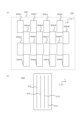
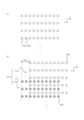
- 5A is a diagram for explaining an example of an adjustment pattern used in this example.
- Fig. 5A shows an example of an arrangement of ink dots 402 formed in one main scanning operation for a gap change pattern 410 printed as at least a part of the adjustment pattern.
- Fig. 5B shows an example of the configuration of the gap change pattern 410.
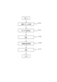
- 4 is a flowchart showing an example of the operation of the printing system 10.
- 10 is a flowchart showing an example of an operation for calculating a correction value.
- FIG. 1 is a diagram illustrating a printing system 10 that executes a method for adjusting an inkjet printer according to an embodiment of the present invention.
- FIG. 1(a) shows an example of the configuration of the main parts of the printing system 10. Except for the points described below, the printing system 10 may have the same or similar features as a known printing system. For example, in addition to the configuration shown in the figure, the printing system 10 may further have the same or similar configuration as a known printing system.
- the printing system 10 of this example is a printing system that performs printing using an inkjet method, and includes a printing device 12, a scanner 14, an image analysis device 16, and a print control unit 18.
- the printing device 12 is an inkjet printer that performs printing in the printing system 10.
- the printing device 12 of this example also has multiple inkjet heads, and prints an adjustment pattern, which is a pre-set test pattern, on the medium to be printed when adjusting the printing device 12.
- the configuration of the printing device 12 will be explained in more detail later.
- the scanner 14 is an image reading device that reads an image printed on a medium by the printing device 12.
- the scanner 14 in this example reads the adjustment pattern printed on the medium when adjusting the printing device 12.
- the scanner 14 By reading the adjustment pattern using the scanner 14, the adjustment pattern can be easily and appropriately read without the printing device 12 having a special configuration for reading images.
- the scanner 14 it is also possible to easily and appropriately read images at high resolution.
- a scanner that is connected to a computer and reads images according to the control of the computer can be used.
- a scanner 14 for example, a scanner whose maximum readable document size is A4 size or less can be suitably used.
- a scanner with a reading resolution of 2400 dpi or more (for example, about 2400 to 4800 dpi, preferably about 2400 to 3000 dpi).
- the adjustment pattern can be properly read using a commercially available inexpensive PC scanner or the like.
- a general-purpose PC or the like can be suitably used as the computer to which the scanner 14 is connected.
- the image analyzer 16 is used as this computer.
- the image analysis device 16 is a computer that performs image analysis on a pattern image that is an image showing an adjustment pattern, and performs image processing on a pattern image that is generated by reading the adjustment pattern with the scanner 14. In addition, the image analysis device 16 thereby calculates correction values used to control the operation of the printing device 12, and calculates numerical values that indicate the state of the inkjet head of the printing device 12, etc.
- the image analysis device 16 in this example is a computer such as a PC, and calculates numerical values such as a predetermined correction value based on the adjustment pattern according to an image analysis tool that is a program that causes the computer to function as an image analysis device. The image analysis device 16 also supplies the calculated correction value to the print control unit 18.
- the image analysis device 16 in this example generates an analysis result file that is a file that indicates the analysis result as an analysis report that indicates the result of the analysis in the image processing.
- the numerical values calculated by the image analysis device 16 and the operation of the image analysis device 16 will be explained in more detail later.
- the print control unit 18 is a computer (control PC) that controls the operation of the printing device 12, and controls the operation of the printing device 12 according to a program.
- the print control unit 18 manages a database 20 that stores control setting values, and controls the operation of the printing device 12 based on the control setting values stored in the database 20.
- the control setting values are an example of setting values for controlling the operation of the printing device 12.
- the database 20 in this example is an example of a setting value storage unit that stores control setting values, and is configured as part of the print control unit 18.
- the control setting values stored in the database 20 are stored in the storage device (HDD or SSD, etc.) of the print control unit 18.
- the database 20 in this example stores multiple types of control setting values, each of which is associated with a different operation in the printing device 12.
- the database 20 may be placed outside the print control unit 18.
- the print control unit 18 in this example stores the above correction values received from the image analysis device 16 in the database 20 as at least a part of the control setting values. This also allows the print control unit 18 to control the operation of the printing device 12 using the correction values calculated by the image analysis device 16. With this configuration, it is possible to appropriately adjust the operation of the printing device 12 based on the correction values calculated based on the adjustment pattern.
- FIG. 1B shows an example of the configuration of the main parts of the printing device 12. Except for the points described above and below, the printing device 12 may have the same or similar features as known printing devices. For example, the printing device 12 may further have the same or similar configuration as known printing devices in addition to the configuration shown in the figure.
- the printing device 12 in this example has a head unit 102, a base unit 104, a Y bar unit 106, a main scanning drive unit 112, a sub-scanning drive unit 114, a drive signal output unit 116, a head position adjustment unit 118, and a control unit 120.
- the head unit 102 is a part that ejects ink onto the medium 50 to be printed.
- the head unit 102 in this example has multiple inkjet heads, and ejects ink from each inkjet head to an ejection position on the medium 50 that is set according to the printing resolution.
- Each inkjet head ejects ink to at least some of the ejection positions that are selected according to the image to be printed from among the ejection positions that are set according to the printing resolution.
- the specific configuration of the head unit 102 will be described in more detail later.
- the base 104 is a platform-like member that holds the medium 50 in a position facing the head unit 102.
- the base 104 in this example is a flatbed type platform, and as shown in the figure, the entire medium 50 is placed on the top surface, thereby holding the medium 50 facing the head unit 102.
- the Y bar unit 106 is a member that extends in the width direction of the medium 50 at a position facing the base 104 across the medium 50, and holds the head unit 102 in a position facing the medium 50.
- the width direction of the medium 50 in this example is a direction parallel to the main scanning direction (Y direction in the figure) that is preset in the printing device 12.
- the main scanning direction is a direction perpendicular to the vertical direction.
- the Y bar unit 106 also includes a guide rail or the like that guides the movement of the head unit 102 in the main scanning direction, and guides the movement of the head unit 102 in the main scanning direction during main scanning operation.
- the main scanning operation is an example of an operation in which the head unit 102 ejects ink while moving relative to the medium 50 in the main scanning direction.
- the main scanning drive unit 112 is a drive unit that causes the head unit 102 to perform a main scanning operation.
- the main scanning drive unit 112 moves the head unit 102 along the Y bar portion 106 while causing each inkjet head of the head unit 102 to eject ink, thereby causing the head unit 102 to perform a main scanning operation.
- the main scanning drive unit 112 supplies the drive signal received from the drive signal output unit 116 to the inkjet heads in accordance with the control of the control unit 120, and ejects ink from each nozzle of each inkjet head according to the image to be printed.
- the drive signal is an example of a signal that causes each of the multiple inkjet heads to eject ink.
- the drive signal can also be considered as a signal for driving a drive element (such as a piezo element) that ejects ink from the nozzle of the inkjet head.
- the sub-scanning drive unit 114 is a drive unit that causes the head unit 102 to perform a sub-scanning operation.
- the sub-scanning operation is an example of an operation that moves the head unit 10 relative to the medium 50 in a sub-scanning direction (X direction in the figure) perpendicular to the main scanning direction and the vertical direction.
- the sub-scanning operation can also be considered as an operation that changes the position of the medium 50 facing the head unit 102 during the main scanning operation.
- the sub-scanning drive unit 114 changes the area on the medium 50 from which ink is ejected in the next main scanning operation by causing the head unit 102 to perform a sub-scanning operation between main scanning operations.
- the head unit 102 can appropriately perform a main scanning operation for each position on the medium 50.
- the sub-scanning drive unit 114 in this example causes the head unit 102 to perform a sub-scanning operation by moving the Y bar unit 106 together with the head unit 102 by a predetermined sub-scanning movement amount with respect to the base unit 104, whose position is fixed, according to the control of the control unit 120.
- the sub-scanning movement amount is an example of the amount of movement of multiple inkjets relative to the medium 50 during a sub-scanning operation.
- the drive signal output unit 116 is an output unit that supplies drive signals for driving the inkjet heads to the multiple inkjet heads of the head unit 102.
- the drive signal output unit 116 supplies drive signals to the drive elements of each inkjet head via the main scanning drive unit 112, thereby causing ink to be ejected from the nozzles of each inkjet head.
- This also causes the drive signal output unit 116 to supply drive signals to each of the multiple nozzles in the inkjet head.
- Supplying a drive signal to each nozzle can also be thought of as being able to adjust the drive signal individually for each nozzle.
- One example of adjusting the drive signal is adjusting the voltage of the drive signal. Adjusting the voltage of the drive signal can also be thought of as adjusting the voltage at least at some of the timings of the drive signal.
- the head position adjustment unit 118 is an adjustment unit that changes the height of the inkjet head in the vertical direction.
- the head position adjustment unit 118 changes the height of at least a part of the Y bar portion 106, thereby moving the head portion 102 in the vertical direction and changing the height of the inkjet head.
- the head position adjustment unit 118 changes the height of the inkjet head in accordance with the thickness of the medium 50.
- the head position adjustment unit 118 in this example changes the height of the inkjet head during the operation of printing the adjustment pattern.
- the head position adjustment unit 118 changes the height of the inkjet head between at least one of the multiple main scanning operations performed to print the adjustment pattern, thereby making the height of the inkjet head different when the main scanning operation before and after that is performed.
- the operation of changing the height of the inkjet head when printing the adjustment pattern will be explained in more detail later.
- the control unit 120 is a part including the CPU of the printing device 12, and controls the operation of each part of the printing device 12 according to a program such as firmware of the printing device 12.
- the control unit 120 can also be considered as a configuration corresponding to a control unit in the printing device 12.
- the control unit 120 in this example controls the operation of each part of the printing device 12 based on the control setting values stored in the database 20. As a result, the control unit 120 operates each part of the printing device 12 based on the control setting values.
- the control unit 120 controls the operation of the main scanning drive unit 112, for example, based on the control setting values stored in the database 20. As a result, the main scanning drive unit 112 causes the head unit 102 to perform a main scanning operation based on the control setting values.
- the head unit 102 can perform a main scanning operation with higher accuracy.
- the control unit 120 also adjusts the amount of sub-scanning movement in the sub-scanning operation based on the correction value stored in the database 20 as the control setting value. This allows the head unit 102 to perform the sub-scanning operation with higher accuracy.
- the control unit 120 in this example also changes the voltage of the drive signal supplied to each nozzle of the inkjet head based on the correction value stored in the database 20 as the control setting value. It is possible to use a correction value other than the correction value for the other adjustments described above as the correction value for adjusting the voltage of the drive signal.
- FIG. 2 is a diagram illustrating the specific configuration of the head unit 102.
- FIG. 2(a) shows an example of the configuration of the head unit 102.
- FIG. 2(b) shows an example of the configuration of the inkjet head 202.
- the head unit 102 in this example has a carriage 200 and multiple inkjet heads 202.
- the carriage 200 is a holding member that holds the multiple inkjet heads 202, and holds the multiple inkjet heads 202, which are distinguished in the figure by the reference characters 202a1 to d4, facing the base unit 104 (see FIG. 1). Holding the inkjet heads 202 facing the base unit 104 can be considered as holding the inkjet heads 202 so that ink is ejected toward the medium on the base unit 104.
- the carriage 200 of this example holds the inkjet heads 202 in a configuration in which the inkjet heads 202 are arranged in a staggered arrangement in the sub-scanning direction, and the rows are arranged in the main scanning direction.
- four inkjet heads 202 shown as inkjet heads 202a1-a4 form a first row in a staggered arrangement.
- Four inkjet heads 202 shown as inkjet heads 202b1-b4 form a second row in a staggered arrangement.
- Four inkjet heads 202 shown as inkjet heads 202c1-c4 form a third row in a staggered arrangement.
- inkjet heads 202 shown as inkjet heads 202d1-d4 form a fourth row in a staggered arrangement.
- Arranging the inkjet heads 202 in a staggered arrangement can be considered as arranging the inkjet heads 202 in the sub-scanning direction with their positions shifted in the main scanning direction.
- the inkjet heads 202 may be arranged in the sub-scanning direction so that they overlap in part in the sub-scanning direction.
- the four inkjet heads 202 arranged in a staggered arrangement are arranged in the sub-scanning direction so that adjacent inkjet heads 202 overlap in part in the sub-scanning direction while alternately shifting their positions in the main scanning direction, as shown in the figure, for example.
- the inkjet heads 202 arranged in a staggered arrangement can be used as one large virtual inkjet head. More specifically, the nozzles of the inkjet heads 202 arranged in a staggered arrangement can be combined to form one virtual nozzle row. As shown in the figure, the first to fourth rows of the inkjet heads 202 in this example are aligned in the main scanning direction with their positions in the sub-scanning direction aligned. In this case, it can be considered that the virtual nozzle rows corresponding to each staggered arrangement are aligned in the main scanning direction.
- the inkjet heads 202 arranged in each staggered arrangement eject ink of the same color, and the inkjet heads 202 arranged in different staggered arrangements eject ink of different colors.
- the carriage 200 holds the inkjet heads 202 divided into the first to fourth rows as in this example, it is possible that the inkjet heads 202 in each of the first to fourth rows eject ink of each process color.
- Each process color is a basic color in the subtractive color mixing method of color expression.
- inks of each process color inks of Y (yellow), M (magenta), C (cyan), and K (black) can be used. By using such inks, high quality color printing can be performed.
- some of the inkjet heads 202 arranged in a staggered arrangement may eject ink of a different color from the other inkjet heads 202 in the same staggered arrangement.
- the head unit 102 can eject ink of more colors. It is also possible to eject ink of the same color from multiple inkjet heads 202 arranged in a staggered arrangement.
- the number and arrangement of the inkjet heads 202 are not limited to the example shown in FIG. 2(a) and can be modified in various ways.
- the head unit 102 may further have other configurations in accordance with the ink ejected from the inkjet heads 202.
- the head unit 102 may further have an ultraviolet light source, etc.
- the inkjet head 202 of this example has multiple nozzle rows 212, as shown in FIG. 2B, for example.
- the nozzle rows 212 are rows in which multiple nozzles are arranged with their positions shifted in a predetermined nozzle row direction.
- the nozzle row direction in this example is parallel to the sub-scanning direction.
- the multiple nozzles in each nozzle row 212 are aligned in the main scanning direction at a constant nozzle interval.
- the multiple nozzle rows 212 are aligned in the main scanning direction with their positions in the sub-scanning direction slightly shifted. For example, it is possible to shift the positions in the sub-scanning direction between the nozzle rows 212 by a distance less than the nozzle interval in one nozzle row 212.
- the distance between nozzles in one inkjet head 202 in the sub-scanning direction (the minimum distance between nozzles in the sub-scanning direction in the inkjet head 202) can be made shorter than the nozzle interval in one nozzle row 212. This makes it possible to perform high-resolution printing at high speed.
- FIG. 2(b) shows a simplified example of the configuration of the inkjet head 202 when the number of nozzle rows 212 in one inkjet head 202 is four.
- the number of nozzle rows 212 in one inkjet head 202 may be other than four.
- the image analysis device 16 in this example calculates numerical values such as predetermined correction values based on the adjustment pattern in accordance with the image analysis tool.
- the image analysis tool a program with the configuration shown in Figure 3 is used.
- FIG. 3 shows an example of the configuration of an image analysis tool.
- the image analysis tool in this example is a program executed in the image analysis device 16 (see FIG. 1), and is composed of multiple modules.
- the image analysis tool also has the following multiple modules: an analysis tool main body 302, a pattern analysis library 304, multiple adjustment item libraries 306, and a report creation library 308.
- the analysis tool main body 302 is a module that serves as the tool main body that controls the entire image analysis tool.
- the analysis tool main body 302 in this example is a file in executable file format (e.g., an exe format file), and performs data input/output processing (I/O processing) for the image analysis tool, and manages data input/output processing between modules in the image analysis tool.
- executable file format e.g., an exe format file
- the analysis tool main body 302 in this example displays a user interface (UI) on the monitor of the image analysis device 16, for example, and reads the pattern image and model parameters by the user selecting a file.
- the pattern image is an image generated by reading the adjustment pattern printed on a medium with the scanner 14 (see FIG. 1).
- the pattern image is stored, for example, in the storage device of the image analysis device 16, and is read into the image analysis tool by the user selecting it in the above user interface.
- the pattern image read into the image analysis tool is an example of an analysis image to be analyzed.
- the model parameters are parameters that are set according to the model of the printing device 12 (see FIG. 1) used to print the adjustment pattern.
- model parameters for example, parameters indicating the arrangement of the inkjet head in the head unit 102 (see FIG. 2) and the configuration of the inkjet head can be used.
- a parameter indicating the arrangement of inkjet heads it is possible to use a parameter indicating the number of inkjet heads or the number of inkjet heads arranged in a staggered arrangement.
- the image analysis device 16 in this example outputs correction value data and an analysis report as the output of the operation performed according to the image analysis tool.
- the image analysis device 16 outputs a file indicating the correction value calculated by the image analysis device 16 as the correction value data.
- the analysis report it outputs an analysis result file indicating the analysis result.
- the correction value data can be considered as a file for feeding back the correction value to the printing device 12.
- the image analysis device 16 outputs the correction value data by generating a file indicating the correction value in a predetermined format.
- a program e.g., an adjustment tool
- that manages the information stored in the database 20 is executed by the image analysis device 16 or another computer, thereby storing the correction value in the database 20.
- the correction value may be directly stored in the database 20 during the operation of the image analysis device 16 performed according to the image analysis tool.
- the analysis result file for example, a file in PDF format or a spreadsheet file format can be used.
- the analysis report output by the analysis result file can be considered as a report in which the adjustment level in the printing device 12 is quantified and summarized in a format that is easy for people to read. Additionally, the analysis report may be used for evidence management at the adjustment level.
- the pattern analysis library 304, the multiple adjustment item libraries 306, and the report creation library 308 are modules that function as libraries.
- dynamic link library format (DLL format) files are used as modules for these libraries.
- the pattern analysis library 304 is a library for interpreting a pattern image, and calls a necessary module from the multiple adjustment item libraries 306 based on the result of interpreting the pattern image.
- the pattern analysis library 304 causes the multiple adjustment item libraries 306 to perform various analyses on the pattern image.
- Each of the multiple adjustment item libraries 306 is a library that performs analysis on various items (adjustment items) that are the subject of analysis by the image analysis tool.
- Each of the multiple adjustment item libraries 306 in this example is a library for a different item, and is called from the pattern analysis library 304 as necessary to execute processing related to the corresponding item.
- the image analysis tool in this example is configured to be able to add a necessary adjustment item library 306, for example, when the number of items to be analyzed increases later.
- the multiple adjustment item libraries 306 in this example use libraries for head tilt analysis, head front-rear analysis, head stagger analysis, head voltage analysis, dot position analysis, and feed analysis.
- the head tilt analysis adjustment item library 306 analyzes the mounting angle of the inkjet head 202 (see FIG. 2) relative to the carriage 200 (see FIG. 2).
- the mounting angle of the inkjet head 202 can also be considered as the angle at which the longitudinal direction of the inkjet head 202 deviates from a predetermined correct orientation.
- the head front-rear analysis adjustment item library 306 analyzes the position in the front-rear direction, i.e., the sub-scanning direction, of each inkjet head 202 held on the carriage 200.
- the head stagger analysis adjustment item library 306 analyzes the positional relationship in the front-rear direction between adjacent inkjet heads 202 for multiple inkjet heads 202 arranged in a staggered arrangement.
- the head voltage analysis adjustment item library 306 analyzes the voltage of the drive signal supplied to each inkjet head 202.
- the adjustment item library 306 for dot position analysis analyzes the positions of dots formed by ink ejected from the nozzles of each inkjet head 202.
- the adjustment item library 306 for feed analysis analyzes the amount of sub-scan movement during sub-scan operation.
- the report creation library 308 generates an analysis result file based on the results of the analysis performed in the multiple adjustment item libraries 306.
- the report creation library 308 receives the results of the analysis in each adjustment item library 306 via the analysis tool main body 302 and the pattern analysis library 304.
- the report creation library 308 outputs the analysis result file via the analysis tool main body 302.
- the image analysis device 16 in this example outputs correction value data to store the correction value in the database 20.
- the image analysis device 16 calculates a correction value according to at least some of the analysis results of the multiple adjustment item libraries 306.
- the analysis tool main body 302 receives the correction value from the adjustment item library 306 via the pattern analysis library 304, and outputs correction value data indicating the received correction value.
- head tilt analysis, head front/back analysis, and head stagger analysis are analyses related to mechanical adjustments (mechanical adjustments).
- head voltage analysis, dot position analysis, and feed analysis are analyses related to adjustments of printing operations other than mechanical adjustments (print adjustments).
- correction values are calculated using the adjustment item library 306 for dot position analysis and the adjustment item library 306 for feed analysis, among the adjustment item libraries 306 related to print adjustments.
- the results of the analysis using the adjustment item library 306 that does not calculate correction values are reflected in the analysis result file.
- the results of the analysis using all adjustment item libraries 306, including the results of the analysis using the adjustment item library 306 that calculates correction values are reflected in the analysis result file.
- the image analysis device 16 uses the items shown in FIG. 4, for example, to analyze the state of the printing device 12 based on the positions of the ink dots formed when printing the adjustment pattern. Furthermore, based on the analysis results, a correction value used to adjust the printing device 12 is calculated.
- FIG. 4 is a diagram explaining an example of an analysis performed by the image analysis device 16, and shows an example of the relationship between the state of the printing device 12 related to this analysis and the ink landing position, in relation to an example of an analysis performed by the adjustment item library 306 for dot position analysis.
- FIG. 4(a) shows a simplified diagram of the relationship between the ink ejection directional speed and the ink landing position.
- the inkjet head 202 of the printing device 12 of this example ejects ink while moving in the main scanning direction by the main scanning operation.
- the speed of the ink (ink droplets) ejected from the inkjet head 202 is a composite component of a vertical component (ejection direction) from the inkjet head 202 toward the medium 50 and a component corresponding to the scan speed, which is the moving speed of the inkjet head 202 during the main scanning operation.
- the ink between the inkjet head 202 and the medium 50 gradually approaches the medium 50 while moving in the main scanning direction.
- the flight distance can be considered to change according to the ejection direction speed.
- the ejection direction speed can also be considered as the vertical speed from the inkjet head 202 toward the medium 50.
- the main scanning direction component of the speed of the ink droplet immediately after it is ejected from the nozzle of the inkjet head 202 corresponds to the scan speed.
- the ejection direction speed is a value determined according to the ink volume (volume of the ink droplet).
- the main scanning direction component is a constant value regardless of the nozzle characteristics.
- the ink volume usually varies depending on the variation in the nozzle characteristics. Therefore, the ejection direction speed varies according to the nozzle characteristics.
- the direction of movement of the ink flying between the inkjet head 202 and the medium 50 varies according to the ejection direction speed.
- the flight distance varies according to the ejection direction speed. If the ejection direction speed is relatively small, the flight distance becomes relatively large. If the ejection direction speed is relatively large, the flight distance becomes relatively small.
- the speed of the ink during flight gradually changes due to the influence of air resistance, gravity, etc. Therefore, it is considered that the relationship between the ejection direction speed and the flight distance is more complicated than the relationship shown in FIG. 4(a).
- the effective ejection direction speed of the ink during flight is determined according to the volume of the ink.
- the relationship between the effective ejection direction speed and the flight distance can be considered in the same way as above. In this case, based on the correlation between the ink volume and the effective ejection direction speed, if the ink volume is relatively small, the flight distance is relatively large.
- the flight distance is not measured directly, but rather, a factor corresponding to the difference in flight distance is detected based on the amount of change in landing position (amount of change in the main scanning direction) that occurs when the ejection conditions are made different. Then, by changing the voltage of the drive signal based on this detection result, the ink volume is changed and adjustments are made to the printing device 12. Also, in this example, for example, as shown in FIG. 4(b), the height of the inkjet head 202 is made to differ in multiple steps when printing the adjustment pattern.
- FIG. 4B is a diagram showing an example of printing conditions when printing an adjustment pattern, and shows an example of how to print an adjustment pattern to be analyzed by the image analyzer 16.
- the height of the inkjet head 202 can be changed by the head position adjustment unit 118 (see FIG. 1).
- the head gap which is the distance between the surface of the medium 50 and the nozzle surface at the bottom of the inkjet head 202, can be changed in multiple stages.
- the flight distance also changes. The amount of change in this flight distance can be considered to reflect the difference in the ejection direction speed.
- the amount of change in the flight distance can also be considered to be determined according to the volume of the ink.
- the inventor of the present application confirmed that the amount of change in the flight distance caused by changing the head gap can be associated with the volume of the ink by actually conducting various experiments, etc.
- the diagram on the left side of FIG. 4(b) shows a simplified view of the change in flight distance when the ink volume is appropriate.
- the flight distance becomes distance L1.
- Gap 2 the flight distance becomes distance L2.
- the amount of change ⁇ L in flight distance caused by changing the height of the inkjet head 202 is equal to the difference between distance L1 and distance L2 (L1-L2). This amount of change ⁇ L corresponds to the appropriate ink volume.
- the inkjet head 202 of this example ejects ink from the nozzles in response to the drive signal supplied from the drive signal output unit 116 (see FIG. 1).
- the volume of ink ejected from the nozzles can be changed by changing the voltage of the drive signal. For example, if the volume of ink is not appropriate, it is possible to change the voltage of the drive signal so as to bring the ink volume closer to the appropriate volume.
- the ink can be brought closer to the appropriate volume.
- the image analysis device 16 of this example calculates numerical values such as correction values based on the adjustment pattern printed on the medium 50.
- the image analysis device 16 calculates a correction value for changing the voltage of the drive signal based on the adjustment pattern including a pattern for measuring the change amount ⁇ Lm of the flight distance.
- the image analysis device 16 or the print control unit 18 stores this correction value in the database 20 (see FIG. 1), for example, to adjust the printing device 12. More specifically, the change amount ⁇ L of the flight distance when the ink volume is appropriate is set as a target value (target distance), and the voltage of the drive signal is changed so that the change amount ⁇ Lm of the measured flight distance approaches the target distance.
- the image analysis device 16 of this example calculates a correction value for changing the voltage of the drive signal in this way based on the adjustment pattern.
- Approaching the change amount ⁇ Lm of the flight distance to the target distance can be considered as setting the difference between ⁇ Lm and the target distance to a value within a predetermined tolerance range.
- the image analysis device 16 calculates a correction value for changing the voltage of the drive signal based on a previously prepared relationship between the amount of voltage change and the amount of change in flight distance.
- a parameter indicating the amount of change in flight distance caused by a voltage change per unit voltage (e.g., 1 V) of the drive signal can be used.
- the amount of change in flight distance caused by a voltage change per unit voltage the amount by which the change in measured flight distance ⁇ Lm changes per unit voltage can be used.
- the amount of change in flight distance caused by a voltage change per unit voltage of the drive signal is defined as A
- the voltage adjustment amount dV can be calculated by the above. It is considered that the parameter A differs depending on the type and color of the ink. Therefore, it is considered that a value determined in advance according to the type and color of the ink is used as the parameter A. It is also considered that the change amount ⁇ Lm of the measured flying distance is expressed as the absolute value of the distance as
- -100)/20 +0.5V As a result, the voltage adjustment value after adjustment corresponding to the new correction value becomes +1.5 V according to the calculation formula 2.
- FIG. 5 is a diagram explaining an example of an adjustment pattern used in this example.
- FIG. 5(a) shows an example of the arrangement of ink dots 402 formed in one main scanning operation when printing a gap change pattern 410 that is printed as at least a part of the adjustment pattern to perform the adjustment explained using FIG. 4.
- FIG. 5(b) shows an example of the configuration of the gap change pattern 410.
- the printing device 12 (see FIG. 1) of this example prints the gap change pattern 410 by performing multiple main scanning operations. Then, by changing the height of the inkjet head 202 (see FIG. 2) between at least one of the multiple main scanning operations for printing the gap change pattern 410, the height of the inkjet head 202 is made different when the main scanning operation is performed before and after that. In each main scanning operation, the printing device 12 ejects ink at a predetermined interval during the main scanning operation using the nozzle to be adjusted in the inkjet head 202, thereby forming an array of ink dots 402 aligned in the main scanning direction on the medium, for example, as shown in FIG. 5A.
- the multiple dots 402 aligned in the main scanning direction with their positions aligned in the sub-scanning direction are formed by the same nozzle.
- the printing device 12 also performs a sub-scanning operation between main scanning operations, for example, as in normal printing.
- a sub-scanning operation between main scanning operations for example, as in normal printing.
- the dots 402 are formed by the same nozzle, their positions in the sub-scanning direction will be shifted if they are formed by different main scanning operations. Therefore, for dots 402 formed by the same nozzle through multiple main scanning operations with different head gaps, it is possible to identify in which main scanning operation the dots 402 were formed, based on the position of the dots 402 in the sub-scanning direction.
- the gap change pattern 410 of this example includes a first pattern 412 and a second pattern 414 that are drawn with their positions shifted from each other in the sub-scanning direction, as shown in FIG. 5B.
- the ink dots 402 included in the first pattern 412 are shown as white circles, and the dots 402 included in the second pattern 414 are shown with a cross-hatched pattern.
- the first pattern 412 of this example is a pattern drawn with the head gap set to a first distance.
- the second pattern 414 is a pattern drawn with the head gap set to a second distance different from the first distance.
- the first pattern 412 is a pattern drawn by ink ejected from the inkjet head 202 when the inkjet head 202 moving in the main scanning operation reaches a predetermined position in the main scanning direction.
- the printing device 12 selects at least some of the nozzles of the inkjet head 202 as nozzles to be adjusted, and ejects ink from the selected nozzles to form a plurality of ink dots 402 constituting the first pattern 412 on the medium.
- the second pattern 414 is a pattern drawn by ink ejected by the inkjet head 202 at the same timing as the first pattern 412 in a main scanning operation in which the head gap is different from that when the first pattern 412 is drawn.
- the ink dots 402 formed when the second pattern 414 is drawn will have the same position in the main scanning direction as the dots 402 of the first pattern 412 if the head gap is set to the above-mentioned first distance.
- the second pattern 414 can also be considered as a pattern in which the position in the main scanning direction at which ink is ejected during the main scanning operation is the same as that when the first pattern 412 was drawn.
- the second pattern 414 can also be considered as a pattern drawn by ink ejected at the timing when the inkjet head 202 moving in the main scanning direction reaches the above-mentioned predetermined position when the first pattern 412 was drawn.
- the position where the ink lands differs between the first pattern 412 and the second pattern 414 due to the difference in the head gap.
- a misalignment occurs in the main scanning direction between the first pattern 412 and the second pattern 414.
- the change in flight distance ⁇ Lm can be measured by measuring the difference between the position in the main scanning direction of the first pattern 412 and the position in the main scanning direction of the second pattern 414.
- the measured change in flight distance ⁇ Lm is equal to the change in flight distance ⁇ L when the ink volume is appropriate.
- the gap change pattern 410 is actually drawn, the ink volume differs for each nozzle due to variations in nozzle characteristics, etc., so the first pattern 412 and the second pattern 414 are deviated in a manner that reflects the ink volume corresponding to each nozzle.
- the first pattern 412 and the second pattern 414 in the gap change pattern 410 can be considered to be patterns that allow the change in flight distance ⁇ Lm to be detected for each nozzle.
- the change in flight distance ⁇ Lm can be properly measured for each nozzle to be adjusted. This also allows proper individual adjustments to be made to each nozzle of the inkjet head 202 when adjusting the drive signal using the gap change pattern 410.
- the arrangement of the dots 402 in the first pattern 412 and the second pattern 414 is formed so that the positions in the sub-scanning direction of the arrangement of the dots 402 in the first pattern 412 do not overlap with the positions in the sub-scanning direction of the arrangement of the dots 402 in the second pattern 414, as shown in FIG. 5(b), for example.
- this configuration it is possible to more easily and appropriately distinguish the arrangement of the dots 402 in the first pattern 412 from the arrangement of the dots 402 in the second pattern 414.
- FIG. 6 is a flowchart showing an example of the operation of the printing system 10.
- the printing device 12 is made to print an adjustment pattern on a medium (S102).
- the operation of step S102 in this example is an example of the operation of the pattern printing stage.
- the pattern printing stage is a stage in which the printing device 12 is made to print a predetermined test pattern on a medium.
- the printing device 12 prints an adjustment pattern in response to an instruction from the printing control unit 18.
- the printing control unit 18 makes the printing device 12 print an adjustment pattern dynamically generated in accordance with the configuration of the printing device 12.
- an adjustment pattern generated in accordance with the adjustment item to be executed can be used.
- the printing control unit 18 makes the printing device 12 print an adjustment pattern including a pattern corresponding to the adjustment item to be executed in accordance with the adjustment item to be executed.
- the print control unit 18 when adjusting the voltage of the drive signal, causes the printing device 12 to print an adjustment pattern including a gap change pattern 410.
- the print control unit 18 causes the printing device 12 to perform multiple main scanning operations with different head gaps. In other words, the print control unit 18 causes the printing device 12 to print an adjustment pattern that is drawn with the head gap changed in multiple stages. It is also conceivable that the printing system 10 may simultaneously adjust multiple adjustment items. In this case, the print control unit 18 causes the printing device 12 to print an adjustment pattern that includes multiple types of patterns corresponding to multiple adjustment items.
- the printing device 12 prints the adjustment pattern on the medium within a printing range of A4 size or smaller.
- a commercially available inexpensive PC scanner or the like can be used as the scanner 14.
- the printing device 12 in this example prints the adjustment pattern on a medium of A4 size or smaller, which is smaller than the maximum size medium that can be held by the stand 104. More specifically, in step S102 in this example, the printing device 12 prints the adjustment pattern on the A4 size medium.
- Such an operation can also be thought of as an operation of printing the adjustment pattern within a printing range narrower than the printable range of the printing device 12.
- the size of the adjustment pattern is, for example, A3 size or larger, it is possible that the size of the file generated by reading the image with the scanner 14 will be extremely large. For this reason, it is preferable to set the range for printing the adjustment pattern to A4 size or smaller.
- the range for printing the adjustment pattern may be set to A4 size or smaller.
- the print control unit 18 causes the printing device 12 to print the adjustment pattern on each of the multiple media. In this case, the pattern printed on each medium is a part of the adjustment pattern. With this configuration, even if all of the necessary patterns cannot be printed on one A4 size medium, it is possible to have the printing device 12 print all of the necessary patterns on multiple media.
- step S104 the medium on which the adjustment pattern is printed is read by the scanner 14 to generate a pattern image showing the adjustment pattern (S104), and the image analyzer 16 analyzes the pattern image (S106).
- the operation of step S104 in this example is an example of an operation in the pattern reading stage.
- the reading of the image by the scanner 14 in step S104 can be performed in the same manner as or similar to a known method of reading an image by the scanner 14.
- the operation of step S106 in this example is an example of an operation in the analysis stage.
- the analysis stage is a stage in which the results of reading the test pattern printed on the medium are analyzed.
- step S106 in this example the image analyzer 16 performs predetermined image processing and calculations, etc., as an analysis of the pattern image.
- the image analyzer 16 calculates correction values used to control the operation of the printer 12 and calculates numerical values indicating the state of the inkjet head in the printer 12.
- the operation of step S106 in this example is also an example of an operation in which a computer performs an analysis process.
- the analysis stage can be considered as a stage in which the computer analyzes the pattern image, thereby analyzing the results of reading the test pattern.
- the image analysis device 16 or the print control unit 18 or the like updates the control setting value stored in the database 20 based on the correction value (S108).
- the operation of step S108 in this example is an example of the operation of the setting value update stage and the adjustment stage.
- the setting value update stage is a stage in which at least a part of the control setting value is updated based on the result of the analysis in the analysis stage.
- the adjustment stage can also be considered as a stage in which adjustments are made to reflect the result of the analysis in the analysis stage in the operation of the printing device 12.
- the operation of updating at least a part of the control setting value is an example of an adjustment operation for the printing device 12.
- step S108 in this example the image analysis device 16 outputs the correction value data and the analysis result file based on the result of the analysis in step S106. Then, as described above, the image analysis device 16 or the print control unit 18 or the like executes a program that manages the information stored in the database 20, thereby storing the correction value in the database 20 based on the correction value data.
- step S108 of this example the control setting value for adjusting the voltage of the drive signal corresponding to each nozzle of the inkjet head is changed based on the results of the analysis in the analysis stage. This causes the results of the analysis in the analysis stage to be reflected in the operation of the printing device 12.
- the adjustment pattern is read by the scanner 14, and predetermined image processing and calculations are performed by the image analysis device 16, so that the correction values used to adjust the printing device 12 can be calculated appropriately.
- the calculated correction values can be stored in the database 20, so that the printing device 12 can be adjusted easily and appropriately.
- the printing control unit 18 causes the printing device 12 to execute a printing operation based on the updated control setting values (S110).
- the printing operation that the printing device 12 executes in step S110 is an example of a printing operation for producing a desired printed matter. According to this example, adjustments can be made appropriately to the printing device 12. Furthermore, after making the necessary adjustments to the printing device 12, the printing device 12 can properly produce a printed matter.
- the reading and analysis of the test pattern and the adjustment based on the analysis result can be performed automatically by the image analysis device 16, etc., without the need for the subjective judgment of the operator.
- the reading result of the test pattern is analyzed by image processing in the image analysis device 16, and the printing device 12 is adjusted based on the result, so that it is possible to prevent differences in the adjustment results due to the individual differences of the operator performing the adjustment.
- This also makes it possible to prevent differences in the print image quality of each printing device 12 from occurring for each individual printing device 12.
- the occurrence of differences in image quality for each individual printing device 12 means that differences in print results occur between printing devices 12 of the same configuration.
- the occurrence of differences in print results between printing devices 12 of the same configuration means that differences in the ink capacity (ejection amount) occur between multiple printing devices 12 using the same product inkjet head 202 and ink, due to the influence of individual differences in each inkjet head 202, resulting in differences in the color of the printed matter.
- adjustments to the printing device 12 can be easily and appropriately performed even when the printing device 12 has a large number of inkjet heads 202 or a large number of nozzles in the inkjet heads 202.
- some of the work may be performed by an operator. In this case, it can be considered that the adjustment work can be semi-automated by image processing using the image analysis device 16. Also, in this case, by semi-automating the adjustment work, the time required for adjustments and the burden on the operator can be reduced.
- adjustments to the printing device 12 are made when the printing device 12 is manufactured.
- the printing device 12 can be made to print a test pattern in the normal printing environment in which the printing device 12 is used, and the printing device 12 can be easily and appropriately adjusted.
- the test pattern can be appropriately read using, for example, a commercially available scanner 14. It is conceivable that such post-shipment adjustments can be made by maintenance personnel dispatched from the mechanism of the printing device 12 at the base where the printing device 12 is used. It is also conceivable that the post-shipment adjustments can be made by the user who owns the printing device 12 himself.
- FIG. 7 is a flow chart showing an example of the operation for calculating the correction value in step S106, and shows an example of the operation for calculating the correction value when adjusting the voltage of the drive signal as described with reference to FIGS. 4 and 5.
- the image analyzer 16 detects the amount of misalignment of the positions of the first pattern 412 and the second pattern 414 in the gap change pattern 410 in the main scanning direction by analyzing the pattern image generated by reading the adjustment pattern including the gap change pattern 410 with the scanner 14 (S202). As can be understood from the matters described with reference to FIGS.
- this misalignment in this example corresponds to the amount of change in the ink landing position in the main scanning direction caused by the difference in the head gap.
- this amount of change corresponds to the measured value of the change in the flying distance ⁇ Lm caused according to the difference in the head gap. Therefore, detecting the amount of misalignment of the positions of the first pattern 412 and the second pattern 414 in the main scanning direction corresponds to analyzing the difference in the ink landing position caused by the difference in the head gap.
- the first pattern 412 and the second pattern 414 in the gap change pattern 410 in this example are patterns that can detect the change in flight distance ⁇ Lm for each nozzle. Therefore, in step S202 in this example, the image analyzer 16 measures the change in flight distance ⁇ Lm for each nozzle by detecting the positional deviation in the main scanning direction of the first pattern 412 and the second pattern 414 for each nozzle to be adjusted in the inkjet head 202. Detecting the positional deviation in the main scanning direction of the first pattern 412 and the second pattern 414 for each nozzle means detecting the positional deviation in the main scanning direction for each position corresponding to each nozzle in the first pattern 412 and the second pattern 414.
- the change in flight distance ⁇ Lm in this example corresponds to the volume of ink.
- the volume of ink ejected from the nozzle of the inkjet head 202 can be adjusted by changing the voltage of the drive signal.
- the ink volume can be adjusted by changing the voltage of the drive signal based on the amount of change in flight distance ⁇ Lm. Therefore, in the following operation, the image analysis device 16 of this example calculates a correction value for adjusting the voltage of the drive signal based on the amount of change in flight distance ⁇ Lm.
- the image analyzer 16 checks whether the change in flight distance ⁇ Lm for each nozzle measured in step S202 is equal to a preset target distance ⁇ L (S204). If the change in flight distance ⁇ Lm is equal to the target distance ⁇ L, this means that the difference between the two is within a predetermined tolerance. If the change in flight distance ⁇ Lm and the target distance ⁇ L are equal for all nozzles to be adjusted (S204, Yes), it determines that no adjustment to the voltage of the drive signal is necessary, and ends the adjustment operation without calculating a new correction value. Then, the process proceeds to step S110, and the printer 12 is caused to perform a printing operation. In other words, the operation of step S108 in the flowchart shown in FIG. 6 is omitted.
- step S204 if it is determined that the flight distance change amount ⁇ Lm and the target distance ⁇ L are not equal for any nozzle (S204, No), the image analysis device 16 calculates the voltage adjustment amount dV for each nozzle based on the flight distance change amount ⁇ Lm measured for that nozzle for all nozzles determined to be unequal (S206). The image analysis device 16 calculates the voltage adjustment amount dV according to the calculation formula 1 described using FIG. 4. Furthermore, the image analysis device 16 calculates a voltage adjustment value adjusted according to the calculated voltage adjustment amount dV according to the calculation formula 2 described using FIG. 4 as a correction value corresponding to the flight distance change amount ⁇ Lm for each nozzle (S208).
- the image analysis device 16 in this example further checks the completion of the adjustment after calculating the correction value in step S208 (S210).
- the gap change pattern 410 is printed by the printing device 12 using the adjusted correction value, and it is confirmed that the measured flight distance change amount ⁇ Lm and the target distance ⁇ L are equal for all nozzles to be adjusted.
- the user may check whether there is a problem with the result displayed by the image analysis tool, thereby checking the completion of the adjustment.
- step S210 determines whether the adjustment is not complete. If it is determined in step S210 that the adjustment is not complete, the process returns to step S206 and the subsequent operations are repeated. With this configuration, the correction value for adjusting the ink volume can be calculated with higher accuracy. Also, if it is determined in step S210 that the adjustment is not complete, it can be corrected so that a correct adjustment result is obtained. Also, if it is determined in step S210 that the adjustment is complete, the operation in step S106 ends and the process proceeds to step S108. In step S108, the image analysis device 16 outputs the correction value data and the analysis result file based on the correction value calculated in the above operation.
- step S108 the image analyzer 16 or the print controller 18, etc., adjusts the voltage of the drive signal supplied to the inkjet head 202 based on the change in the landing position by reflecting the correction value calculated in step S106 in the database 20.
- the correction value for each nozzle is reflected in the database 20 for the drive signal for each nozzle, and the voltage is adjusted based on the deviation for each nozzle.
- the drive signal for each nozzle can be appropriately adjusted.
- the state of the printing device 12 can be appropriately detected with respect to the volume of ink ejected from the nozzles of the inkjet head 202 based on the change in the landing position of the ink in the main scanning direction detected using the adjustment pattern. Also, based on the detection result, appropriate adjustments can be made to the printing device 12.
- the adjustment pattern used in this example is an example of a pattern in which ink is ejected from the inkjet head 202 from different heights.
- the operation of step S106 detects the amount of change in the ink landing position in the main scanning direction by measuring the distance in the main scanning direction between two ink dots formed by the landing of ink ejected from two different heights.
- the operation of step S108 based on the results calculated in step S106 can be considered to be an operation of making an adjustment based on the amount of change in the landing position.
- the operation of step S108 can also be considered to be an operation of making an adjustment to change the volume of ink ejected from the nozzle based on the results of the analysis in step S106.
- the image analysis device 16 of this example calculates the correction value according to the above calculation formulas 1 and 2.
- This correction value is a value calculated based on the result of comparing the measured flight distance change amount ⁇ Lm with the target distance ⁇ L.
- the measured flight distance change amount ⁇ Lm corresponds to the positional deviation amount in the main scanning direction of the first pattern 412 and the second pattern 414 in the gap change pattern 410 included in the adjustment pattern.
- the target distance ⁇ L corresponds to a preset reference amount. Therefore, the correction value calculated in step S106 is a value corresponding to the result of comparing such a reference amount with the deviation amount.
- this reference amount is the deviation amount that should be detected when the ink volume is appropriate. Also, such a deviation amount can be considered as a distance corresponding to the case where the ink volume is appropriate with respect to the distance between the reference position of the first pattern 412 and the reference position of the second pattern 414.
- the operation of step S108 can also be considered as an operation that adjusts the printing device 12 by reflecting the adjustment values, correction values, etc. calculated in response to the target distance in the control of the printing device 12.
- the image analysis device 16 in this example calculates correction values and performs other operations based on a pattern image generated by reading the adjustment pattern with the scanner 14. Therefore, according to this example, even if the printing device 12 does not have a camera or colorimeter for reading the print result, the voltage of the drive signal can be adjusted.
- an inexpensive PC scanner or the like can be used as the scanner 14. Therefore, the voltage of the drive signal can be appropriately adjusted in the environment in which the printing device 12 is used, not only in a factory where the printing device 12 is manufactured, but also at a site where the printing device 12 is used. As a result, even if a discrepancy occurs in the ink capacity due to aging of the printing device 12, adjustments to the printing device 12 can be easily and appropriately performed.
- the voltage of the drive signal is adjusted as an adjustment to the printing device 12.
- the volume of ink ejected from the nozzles of the inkjet head 202 is changed. This is based on the fact that there is a fixed relationship between the volume of ink ejected and the ejection directional speed. In other words, it is based on the fact that there is a monotonically increasing relationship between the ink volume and the effective ejection directional speed of the ink during flight.
- the head gap When measuring the change in flight distance ⁇ Lm, it is desirable to vary the head gap by about 1 mm (0.5 to 2 mm). More specifically, it is conceivable to vary the head gap between two distances, about 1.5 mm and 2.5 mm, and measure the change in flight distance ⁇ Lm. It is also desirable to set the target distance to about 100 ⁇ (about 90 to 140 ⁇ m). It is desirable to set the voltage of the drive signal to a fluctuation range of about -3 V to +3 V from the standard voltage. It is also conceivable that a 1 V change in the voltage of the drive signal will cause a change in the change in flight distance ⁇ Lm of about 10 to 50 ⁇ m (preferably about 15 to 40 ⁇ m). This change corresponds to parameter A in the above formula 1.
- the gap change pattern 410 when using an adjustment pattern including the gap change pattern 410, it is also possible to adjust other than the voltage of the drive signal based on the measured flight distance change amount ⁇ Lm.
- the flight distance change amount ⁇ Lm corresponding to any nozzle differs from the target distance ⁇ L, the volume of ink ejected from that nozzle is not the appropriate amount.
- image processing taking into account the difference between the flight distance change amount ⁇ Lm and the target distance ⁇ L.
- the flight distance of the ink between the inkjet head 202 and the medium varies depending on the head gap.
- the head gap varies depending on the thickness of the medium.
- the amount of change in the landing position of the ink in the main scanning direction which is measured as the amount of change in the flight distance ⁇ Lm, also varies depending on the thickness of the medium.
- the height of the inkjet head 202 is set to a predetermined known height, and the amount of change in the flight distance ⁇ Lm is measured using a nozzle with an appropriate ink volume. Then, based on the above data, the head gap corresponding to the amount of change in the flight distance ⁇ Lm measured is obtained. Also, the thickness of the medium is calculated based on the obtained head gap and the height of the inkjet head 202. With this configuration, the thickness of the medium can be detected when the thickness of the medium is unknown. In addition, adjustments can be made to the printing device 12 based on the detected thickness of the medium. More specifically, adjustments based on the thickness of the medium can include adjusting the height of the inkjet head 202, etc.
- the gap-changing pattern 410 including the first pattern 412 and the second pattern 414 it is also possible to detect matters other than the change amount ⁇ in flight distance. More specifically, when the gap-changing pattern 410 is used, in addition to the change amount ⁇ in flight distance, it is also possible to detect changes in the way ink lands that occur in response to changes in the head gap. As an analysis based on the gap-changing pattern 410, for example, it is also possible to further detect at least one of the mist formation of ink ejected by the inkjet head 202 and the deflection of the ink flight based on the first pattern 412 and the second pattern 414 in the gap-changing pattern 410. With this configuration, it is possible to obtain more diverse information based on a single test pattern.
- the printing system 10 and the printing device 12 can also be modified in various other ways.
- the above mainly describes the configuration and operation of using the scanner 14 to read the adjustment pattern printed on the medium by the printing device 12. This allows the adjustment pattern to be read easily and appropriately without the printing device 12 having a special configuration for reading images. It also becomes possible to use a commercially available inexpensive PC scanner.
- the printing device 12 in this example is an inkjet printer.
- the printing device 12 is an example of a configuration that draws a two-dimensional (2D) image by ejecting ink onto a medium.
- a 3D printer (3D printing device) that creates a three-dimensional object may be used as the printing device 12.
- the present invention can be suitably used, for example, as an adjustment method for an inkjet printer.
Landscapes
- Engineering & Computer Science (AREA)
- Quality & Reliability (AREA)
- Ink Jet (AREA)
Abstract
Description
dV=(|ΔLm|-ΔL)/A (計算式1)
によって、電圧調整量dVを算出することができる。パラメータAは、インクの種類や色によって異なることが考えられる。そのため、パラメータAには、インクの種類や色に合わせて予め決定した値を用いることが考えられる。また、測定される飛翔距離の変化量ΔLmは、上記のように、|ΔLm|として、距離の絶対値を用いることが考えられる。また、このような調整は、駆動信号の電圧を調整するための補正値(制御設定値)である電圧調整値が既に設定されている状態で行うことも考えられる。そして、上記の計算式1で算出される電圧調整量dVについて、下記の計算式2によって、現在の電圧調整値に電圧調整量dVを加算することが考えられる。
(調整後の電圧調整値)=(現在の電圧調整値)+(電圧調整量dV) (計算式2)
dV=(|-110|-100)/20=+0.5V
になる。また、その結果、新たな補正値に対応する調整後の電圧調整値は、計算式2により、+1.5Vになる。
Claims (13)
- インクジェットプリンタの調整方法であって、
媒体に対して所定のテストパターンを前記インクジェットプリンタに印刷させるパターン印刷段階と、
前記媒体に印刷された前記テストパターンの読み取り結果に対する解析を行う解析段階と、
前記解析段階での解析の結果を前記インクジェットプリンタの動作に反映させる調整を行う調整段階と
を含み、
前記インクジェットプリンタは、
インクを吐出するインクジェットヘッドと、
鉛直方向と直交する主走査方向へ移動しつつインクを吐出する主走査動作を前記インクジェットヘッドに行わせる主走査駆動部と、
鉛直方向における前記インクジェットヘッドの高さを変化させるヘッド位置調整部と
を備え、
前記パターン印刷段階において、前記ヘッド位置調整部によって前記インクジェットヘッドの高さを複数段階で異ならせることで、前記媒体の表面と前記インクジェットヘッドの下部のノズル面との間の距離であるヘッドギャップを複数段階で異ならせて、前記インクジェットプリンタに前記テストパターンを印刷させ、
前記解析段階において、前記テストパターンに基づき、前記ヘッドギャップの違いによって生じる前記主走査方向におけるインクの着弾位置の変化量を検知し、
前記調整段階において、前記着弾位置の変化量に基づく調整を行うことを特徴とするインクジェットプリンタの調整方法。 - 前記パターン印刷段階で前記テストパターンが印刷された前記媒体をスキャナで読み取ることで前記テストパターンを示す画像であるパターン画像を生成するパターン読取段階を更に備え、
前記解析段階において、前記パターン画像に対する解析をコンピュータで行うことで、前記テストパターンの読み取り結果に対する解析を行うことを特徴とする請求項1に記載のインクジェットプリンタの調整方法。 - 前記インクジェットプリンタは、前記主走査方向及び鉛直方向と直交する副走査方向へ前記媒体に対して相対的に前記インクジェットヘッドを移動させる副走査駆動部を更に備え、
前記テストパターンは、前記ヘッドギャップを複数段階で異ならせて描かれるパターンであるギャップ変更パターンを含み、
前記ギャップ変更パターンは、
前記ヘッドギャップを第1の距離にして、前記主走査動作において移動している前記インクジェットヘッドが前記主走査方向における所定の位置に来たタイミングで前記インクジェットヘッドが吐出するインクによって描かれる第1パターンと、
前記第1パターンとは前記副走査方向における位置をずらして描かれるパターンであり、前記ヘッドギャップを前記第1の距離とは異なる第2の距離にして、前記主走査動作において移動している前記インクジェットヘッドが前記所定の位置に来たタイミングで前記インクジェットヘッドが吐出するインクによって描かれる第2パターンと
を含み、
前記解析段階において、前記第1パターン及び前記第2パターンの前記主走査方向における位置のズレ量を検知し、
前記調整段階において、前記ズレ量に基づく調整を行うことを特徴とする請求項1に記載のインクジェットプリンタの調整方法。 - 前記解析段階において、前記第1パターン及び前記第2パターンに基づき、前記インクジェットヘッドが吐出するインクのミスト化、及び、インクの飛行曲がりの少なくともいずれかを更に検知することを特徴とする請求項3に記載のインクジェットプリンタの調整方法。
- 前記インクジェットプリンタは、前記インクジェットヘッドを駆動する駆動信号を出力する駆動信号出力部を更に備え、
前記調整段階において、前記着弾位置の変化量に基づき、前記インクジェットヘッドに供給される前記駆動信号の電圧を調整することを特徴とする請求項1に記載のインクジェットプリンタの調整方法。 - 前記インクジェットプリンタは、前記主走査方向及び鉛直方向と直交する副走査方向へ前記媒体に対して相対的に前記インクジェットヘッドを移動させる副走査駆動部を更に備え、
前記テストパターンは、前記ヘッドギャップを複数段階で異ならせて描かれるパターンであるギャップ変更パターンを含み、
前記ギャップ変更パターンは、
前記ヘッドギャップを第1の距離にして、前記主走査動作において移動している前記インクジェットヘッドが前記主走査方向における所定の位置に来たタイミングで前記インクジェットヘッドが吐出するインクによって描かれる第1パターンと、
前記第1パターンと前記副走査方向における位置をずらして描かれるパターンであり、前記ヘッドギャップを前記第1の距離とは異なる第2の距離にして、前記主走査動作において移動している前記インクジェットヘッドが前記所定の位置に来たタイミングで前記インクジェットヘッドが吐出するインクによって描かれる第2パターンと
を含み、
前記解析段階において、前記第1パターン及び前記第2パターンの前記主走査方向における位置のズレ量を検知し、
前記調整段階において、予め設定された基準量と前記ズレ量とを比較した結果に応じて、前記駆動信号の電圧を変化させることを特徴とする請求項5に記載のインクジェットプリンタの調整方法。 - 前記インクジェットヘッドは、複数のノズルを有し、
前記駆動信号出力部は、前記インクジェットヘッドに対し、前記ノズル毎に、前記駆動信号を供給し、
前記ギャップ変更パターンは、前記ノズル毎の前記ズレ量を検知できる前記第1パターン及び前記第2パターンを含み、
前記解析段階において、前記ノズル毎に、前記ズレ量を検知し、
前記調整段階において、前記ノズル毎の前記駆動信号に対し、前記ノズル毎の前記ズレ量に基づき、前記駆動信号の電圧の調整を行うことを特徴とする請求項6に記載のインクジェットプリンタの調整方法。 - 前記調整段階において、印刷すべき画像として前記インクジェットプリンタへ供給される印刷画像に対し、前記着弾位置の変化量に基づき、画像処理を行うことで、前記着弾位置の変化量に基づく調整を行うことを特徴とする請求項1に記載のインクジェットプリンタの調整方法。
- 前記解析段階において、前記着弾位置の変化量に基づき、前記媒体の厚さを検知し、
前記調整段階において、前記媒体の厚さに基づく調整を行うことを特徴とする請求項1に記載のインクジェットプリンタの調整方法。 - コンピュータに画像解析を行わせるプログラムであって、
インクジェットプリンタによって媒体に印刷された所定のテストパターンの読み取り結果に対する解析処理を前記コンピュータに行わせ、
前記インクジェットプリンタは、
インクを吐出するインクジェットヘッドと、
鉛直方向と直交する主走査方向へ移動しつつインクを吐出する主走査動作を前記インクジェットヘッドに行わせる主走査駆動部と、
鉛直方向における前記インクジェットヘッドの高さを変化させるヘッド位置調整部と
を備え、
前記テストパターンは、前記ヘッド位置調整部によって前記インクジェットヘッドの高さを複数段階で異ならせることで、前記媒体の表面と前記インクジェットヘッドの下部のノズル面との間の距離であるヘッドギャップを複数段階で異ならせて、前記インクジェットプリンタに印刷させたパターンであり、
前記解析処理において、前記コンピュータに、
前記テストパターンに基づき、前記ヘッドギャップの違いによって生じる前記主走査方向におけるインクの着弾位置の変化量を検知させ、
前記着弾位置の変化量に基づき、前記インクジェットプリンタの調整に用いる補正値を算出させることを特徴とするプログラム。 - 前記解析処理において、前記テストパターンが印刷された前記媒体をスキャナで読み取ることで生成される画像であるパターン画像に対する解析を前記コンピュータに行わせることで、前記パターン画像に基づき、前記着弾位置の変化量を検知させることを特徴とする請求項10に記載のプログラム。
- インクジェット方式での印刷を行う印刷システムであって、
インクジェット方式での印刷を行うインクジェットプリンタと、
前記インクジェットプリンタによって媒体に印刷された所定のテストパターンの読み取り結果に対する解析処理を行う解析装置と、
を備え、
前記インクジェットプリンタは、
インクを吐出するインクジェットヘッドと、
鉛直方向と直交する主走査方向へ移動しつつインクを吐出する主走査動作を前記インクジェットヘッドに行わせる主走査駆動部と、
鉛直方向における前記インクジェットヘッドの高さを変化させるヘッド位置調整部と
を備え、
前記テストパターンは、前記ヘッド位置調整部によって前記インクジェットヘッドの高さを複数段階で異ならせることで、前記媒体の表面と前記インクジェットヘッドの下部のノズル面との間の距離であるヘッドギャップを複数段階で異ならせて、前記インクジェットプリンタに印刷させたパターンであり、
前記解析装置は、
前記テストパターンに基づき、前記ヘッドギャップの違いによって生じる前記主走査方向におけるインクの着弾位置の変化量を検知し、
前記着弾位置の変化量に基づき、前記インクジェットプリンタの調整に用いる補正値を算出することを特徴とする印刷システム。 - 画像の読み取りを行うスキャナを更に備え、
前記解析装置は、前記テストパターンが印刷された前記媒体を前記スキャナで読み取ることで生成される画像であるパターン画像に対する解析を行うことで、前記パターン画像に基づき、前記着弾位置の変化量を検知することを特徴とする請求項12に記載の印刷システム。
Priority Applications (2)
| Application Number | Priority Date | Filing Date | Title |
|---|---|---|---|
| EP24807125.0A EP4711137A1 (en) | 2023-05-12 | 2024-05-10 | Inkjet printer adjustment method, program, and printing system |
| CN202480030847.6A CN121079207A (zh) | 2023-05-12 | 2024-05-10 | 喷墨打印机的调整方法、程序及印刷系统 |
Applications Claiming Priority (2)
| Application Number | Priority Date | Filing Date | Title |
|---|---|---|---|
| JP2023079315A JP2024163573A (ja) | 2023-05-12 | 2023-05-12 | インクジェットプリンタの調整方法、プログラム、及び印刷システム |
| JP2023-079315 | 2023-05-12 |
Publications (1)
| Publication Number | Publication Date |
|---|---|
| WO2024237173A1 true WO2024237173A1 (ja) | 2024-11-21 |
Family
ID=93519092
Family Applications (1)
| Application Number | Title | Priority Date | Filing Date |
|---|---|---|---|
| PCT/JP2024/017329 Ceased WO2024237173A1 (ja) | 2023-05-12 | 2024-05-10 | インクジェットプリンタの調整方法、プログラム、及び印刷システム |
Country Status (4)
| Country | Link |
|---|---|
| EP (1) | EP4711137A1 (ja) |
| JP (1) | JP2024163573A (ja) |
| CN (1) | CN121079207A (ja) |
| WO (1) | WO2024237173A1 (ja) |
Citations (7)
| Publication number | Priority date | Publication date | Assignee | Title |
|---|---|---|---|---|
| JP2000062158A (ja) | 1998-06-10 | 2000-02-29 | Canon Inc | 液体噴射記録ヘッド等の記録ヘッド検査装置、液体噴射記録ヘッド着弾点検査方法、液体噴射記録ヘッドの製造方法、液体噴射記録ヘッドおよび該ヘッドを搭載可能な液体噴射記録装置 |
| JP2004284124A (ja) * | 2003-03-20 | 2004-10-14 | Seiko Epson Corp | 複数の印刷ヘッドの相互の位置ズレによる印刷ズレの抑制 |
| JP2004314361A (ja) * | 2003-04-14 | 2004-11-11 | Seiko Epson Corp | 液体噴射装置、及びその制御方法 |
| JP2005007727A (ja) * | 2003-06-18 | 2005-01-13 | Seiko Epson Corp | 液体吐出装置、液体吐出方法、及び、印刷システム |
| JP2020111037A (ja) * | 2019-01-17 | 2020-07-27 | セイコーエプソン株式会社 | 液体吐出装置及び液体の着弾位置ズレを補正する方法 |
| JP2020121504A (ja) * | 2019-01-31 | 2020-08-13 | セイコーエプソン株式会社 | ワーキングギャップの決定方法、及び記録装置 |
| JP2022049899A (ja) * | 2020-09-17 | 2022-03-30 | セイコーエプソン株式会社 | 液体吐出装置、及び着弾位置ズレを補正する方法 |
-
2023
- 2023-05-12 JP JP2023079315A patent/JP2024163573A/ja active Pending
-
2024
- 2024-05-10 CN CN202480030847.6A patent/CN121079207A/zh active Pending
- 2024-05-10 WO PCT/JP2024/017329 patent/WO2024237173A1/ja not_active Ceased
- 2024-05-10 EP EP24807125.0A patent/EP4711137A1/en active Pending
Patent Citations (7)
| Publication number | Priority date | Publication date | Assignee | Title |
|---|---|---|---|---|
| JP2000062158A (ja) | 1998-06-10 | 2000-02-29 | Canon Inc | 液体噴射記録ヘッド等の記録ヘッド検査装置、液体噴射記録ヘッド着弾点検査方法、液体噴射記録ヘッドの製造方法、液体噴射記録ヘッドおよび該ヘッドを搭載可能な液体噴射記録装置 |
| JP2004284124A (ja) * | 2003-03-20 | 2004-10-14 | Seiko Epson Corp | 複数の印刷ヘッドの相互の位置ズレによる印刷ズレの抑制 |
| JP2004314361A (ja) * | 2003-04-14 | 2004-11-11 | Seiko Epson Corp | 液体噴射装置、及びその制御方法 |
| JP2005007727A (ja) * | 2003-06-18 | 2005-01-13 | Seiko Epson Corp | 液体吐出装置、液体吐出方法、及び、印刷システム |
| JP2020111037A (ja) * | 2019-01-17 | 2020-07-27 | セイコーエプソン株式会社 | 液体吐出装置及び液体の着弾位置ズレを補正する方法 |
| JP2020121504A (ja) * | 2019-01-31 | 2020-08-13 | セイコーエプソン株式会社 | ワーキングギャップの決定方法、及び記録装置 |
| JP2022049899A (ja) * | 2020-09-17 | 2022-03-30 | セイコーエプソン株式会社 | 液体吐出装置、及び着弾位置ズレを補正する方法 |
Also Published As
| Publication number | Publication date |
|---|---|
| CN121079207A (zh) | 2025-12-05 |
| EP4711137A1 (en) | 2026-03-18 |
| JP2024163573A (ja) | 2024-11-22 |
Similar Documents
| Publication | Publication Date | Title |
|---|---|---|
| JP5063327B2 (ja) | インクジェット記録装置および調整値取得方法 | |
| JP5737950B2 (ja) | 記録装置および記録位置調整方法 | |
| US10369782B2 (en) | Adjustment method of recording head and recording apparatus | |
| EP1029698B1 (en) | Controlling residual fine errors of dot placement in an incremental printer | |
| JP6061550B2 (ja) | 記録装置及びその制御方法 | |
| JP2008230069A (ja) | インクジェット記録装置および記録位置制御方法 | |
| US8857941B2 (en) | Ink discharge amount adjuster for each color of line inkjet printer | |
| JP6021872B2 (ja) | 記録装置および記録位置調整方法 | |
| US8272707B2 (en) | Printing device, control method for a printing device, a program, and a recording medium | |
| JP5383267B2 (ja) | インクジェット記録装置、インクジェット記録装置の記録方法および記録方法 | |
| JP7708654B2 (ja) | インクジェットプリンタの調整方法、プログラム、及び印刷システム | |
| WO2024237173A1 (ja) | インクジェットプリンタの調整方法、プログラム、及び印刷システム | |
| JP5312122B2 (ja) | インクジェット記録装置 | |
| US10870271B2 (en) | Liquid ejecting apparatus and method for driving the same | |
| US11167563B2 (en) | Ink-jet recording apparatus, ink-jet recording method, and ink-jet recording program | |
| US20060066656A1 (en) | Method for reducing dot placement errors in imaging apparatus | |
| JP2024163574A (ja) | 液体吐出装置の調整方法、プログラム、液体吐出システム、検出方法、及び液体吐出装置 | |
| WO2021070662A1 (ja) | 印刷装置及び補正方法 | |
| JP2007144653A (ja) | インクジェット記録装置 | |
| CN121488246A (zh) | 在喷墨式打印机中设置打印头驱动电压的方法和系统 | |
| JP2011194649A (ja) | 画像形成装置 | |
| JP2024180095A (ja) | 記録装置 | |
| JP2021160334A (ja) | 印刷システム及び印刷方法 | |
| JP5868037B2 (ja) | インクジェット記録装置およびインクジェット記録方法 | |
| JP2013166357A (ja) | 印刷装置の調整方法、印刷装置の製造方法、及び、印刷装置 |
Legal Events
| Date | Code | Title | Description |
|---|---|---|---|
| 121 | Ep: the epo has been informed by wipo that ep was designated in this application |
Ref document number: 24807125 Country of ref document: EP Kind code of ref document: A1 |
|
| WWE | Wipo information: entry into national phase |
Ref document number: 2024807125 Country of ref document: EP |
|
| NENP | Non-entry into the national phase |
Ref country code: DE |
|
| ENP | Entry into the national phase |
Ref document number: 2024807125 Country of ref document: EP Effective date: 20251212 |
|
| ENP | Entry into the national phase |
Ref document number: 2024807125 Country of ref document: EP Effective date: 20251212 |
|
| ENP | Entry into the national phase |
Ref document number: 2024807125 Country of ref document: EP Effective date: 20251212 |
|
| ENP | Entry into the national phase |
Ref document number: 2024807125 Country of ref document: EP Effective date: 20251212 |
|
| ENP | Entry into the national phase |
Ref document number: 2024807125 Country of ref document: EP Effective date: 20251212 |
|
| ENP | Entry into the national phase |
Ref document number: 2024807125 Country of ref document: EP Effective date: 20251212 |
|
| ENP | Entry into the national phase |
Ref document number: 2024807125 Country of ref document: EP Effective date: 20251212 |
|
| ENP | Entry into the national phase |
Ref document number: 2024807125 Country of ref document: EP Effective date: 20251212 |
|
| ENP | Entry into the national phase |
Ref document number: 2024807125 Country of ref document: EP Effective date: 20251212 |
|
| WWP | Wipo information: published in national office |
Ref document number: 2024807125 Country of ref document: EP |