WO2024237030A1 - 水素燃焼装置及び水素調理装置 - Google Patents
水素燃焼装置及び水素調理装置 Download PDFInfo
- Publication number
- WO2024237030A1 WO2024237030A1 PCT/JP2024/015788 JP2024015788W WO2024237030A1 WO 2024237030 A1 WO2024237030 A1 WO 2024237030A1 JP 2024015788 W JP2024015788 W JP 2024015788W WO 2024237030 A1 WO2024237030 A1 WO 2024237030A1
- Authority
- WO
- WIPO (PCT)
- Prior art keywords
- hydrogen
- gas
- combustion device
- ejection
- supplied
- Prior art date
- Legal status (The legal status is an assumption and is not a legal conclusion. Google has not performed a legal analysis and makes no representation as to the accuracy of the status listed.)
- Ceased
Links
Images








Classifications
-
- F—MECHANICAL ENGINEERING; LIGHTING; HEATING; WEAPONS; BLASTING
- F23—COMBUSTION APPARATUS; COMBUSTION PROCESSES
- F23D—BURNERS
- F23D14/00—Burners for combustion of a gas, e.g. of a gas stored under pressure as a liquid
- F23D14/20—Non-premix gas burners, i.e. in which gaseous fuel is mixed with combustion air on arrival at the combustion zone
-
- F—MECHANICAL ENGINEERING; LIGHTING; HEATING; WEAPONS; BLASTING
- F23—COMBUSTION APPARATUS; COMBUSTION PROCESSES
- F23D—BURNERS
- F23D14/00—Burners for combustion of a gas, e.g. of a gas stored under pressure as a liquid
- F23D14/46—Details
- F23D14/72—Safety devices, e.g. operative in case of failure of gas supply
- F23D14/82—Preventing flashback or blowback
-
- F—MECHANICAL ENGINEERING; LIGHTING; HEATING; WEAPONS; BLASTING
- F23—COMBUSTION APPARATUS; COMBUSTION PROCESSES
- F23K—FEEDING FUEL TO COMBUSTION APPARATUS
- F23K5/00—Feeding or distributing other fuel to combustion apparatus
Definitions
- the present invention relates to a hydrogen combustion device and a hydrogen cooking device.
- Hydrogen has different physical properties from gases used in conventional cooking devices, such as a fast burning speed and a short quenching distance. For example, hydrogen burns fast, which can lead to so-called backfires, where hydrogen gas burns in unintended places. In addition, the quenching distance of hydrogen is short, making it difficult to extinguish burning hydrogen gas. For this reason, there is a demand for improvements that take into account the physical properties of hydrogen in conventional combustion devices and cooking devices that use hydrogen gas.
- the present invention aims to provide a hydrogen combustion device and a hydrogen cooking device that have been improved by taking into account the physical properties of hydrogen.
- the hydrogen combustion device of the present invention is a hydrogen combustion device that burns hydrogen gas, and is equipped with an ejection body that is a member capable of supplying gas and ejecting the supplied gas to the outside, the ejection body having at least one pipeline, the pipeline having a space to which gas can be supplied, and at least one open hole that is a hole that opens the space to the outside, and the open hole is configured such that the speed at which the gas supplied to the pipeline leaves the open hole is greater than the combustion speed of the hydrogen gas.
- the open hole in the pipeline is configured so that the speed at which the gas supplied to the pipeline flows through the open hole is faster than the speed at which the gas supplied to the pipeline flows through the space.
- the hydrogen combustion device is equipped with a flow rate adjusting body that can adjust the flow rate of the gas supplied to the ejection body.
- the flow rate adjusting body is capable of adjusting the pressure of the gas supplied to the ejection body.
- the supplied gas is prevented from mixing with other gases until it leaves the open hole.
- the ejection body has a plurality of the open holes, and the configuration of the ejection body is adjusted so that gas comes out uniformly from each of the plurality of open holes, and the adjusted configuration of the ejection body includes the diameter of the open hole.
- the hydrogen combustion device of the present invention is a hydrogen combustion device that burns hydrogen gas, and has at least one ejection opening body that is a member to which gas can be supplied and which can eject the supplied gas to the outside, and the ejection opening body has a plurality of passages that guide the gas supplied to the ejection opening body to the outside, and the cross-sectional diameter of the passages is set to a value such that the hydrogen gas in the passages is not burned by the hydrogen gas that comes out of the ejection opening body through the passages and burns.
- the ejection opening has a plurality of pipes, each of which forms a plurality of passages.
- the multiple pipes are arranged in parallel with each other.
- each of the multiple pipelines is surrounded by the other pipelines, and each of the pipelines is in contact with the multiple pipelines that it is surrounded by.
- the ejection opening body has a porous body, and each of the multiple passages is formed by a series of multiple holes in the porous body.
- the cross-sectional diameter of the passage is smaller than 0.64 mm.
- the supplied gas is prevented from mixing with other gases until it is discharged to the outside from the ejection opening.
- the hydrogen cooking device of the present invention is equipped with any one of the hydrogen combustion devices described above.
- the present invention provides a hydrogen combustion device and a hydrogen cooking device that have been improved by taking into account the physical properties of hydrogen.
- FIG. 1 is a schematic diagram showing a general configuration of a hydrogen cooking device according to a first embodiment of the present invention, which is equipped with a hydrogen combustion device according to a first embodiment of the present invention.
- FIG. 2 is a schematic diagram illustrating the configuration of the hydrogen combustion apparatus shown in FIG. 1.
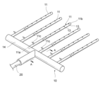
- 3 is a perspective view showing a schematic configuration of an ejection body provided in the hydrogen combustion apparatus shown in FIG. 2.
- FIG. 4 is a cross-sectional perspective view of a pipe line of the ejection body shown in FIG. 3 . 4 is a cross-sectional view showing a cross section of a buffer pipe of the ejection body in a cross section along the line AA in FIG. 3.
- 5 is a cross-sectional view showing a cross section of the pipeline taken along line BB in FIG.
- FIG. 2 is a diagram showing a schematic configuration of a support stand of the hydrogen cooking apparatus shown in FIG. 1 .
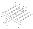
- FIG. 6 is a perspective view of a jet of a hydrogen combustion apparatus according to a second embodiment of the present invention.
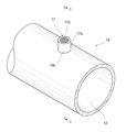
- FIG. 9 is a cross-sectional perspective view of a pipe line of the ejection body shown in FIG. 8 .
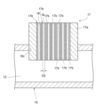
- 10 is a cross-sectional view showing a cross section of the pipeline taken along line CC in FIG. 9.
- FIG. 10 is a diagram showing a part of the duct of the injection opening body shown in FIG. 9 .
- 10 is a diagram showing a modified example of the duct of the injection opening body shown in FIG. 9 .
- FIG. FIG. 10 is a diagram showing a modified example of the injection opening body shown in FIG.
- FIG. 10 is a diagram showing a modified example of the injection opening body shown in FIG. 9 .
- FIG. 13 is a perspective view showing a schematic configuration of a modified example of a pipe for the ejection body. 16 is a cross-sectional view showing a cross section taken along line DD in FIG. 15.
- FIG. 13 is a perspective view showing a schematic configuration of a modified example of the ejection body;
- FIG. 16 is a perspective view showing an example of a hydrogen combustion apparatus provided with an ejection body having the pipe shown in FIG. 15 .
- FIG. 1 is a schematic diagram showing the general configuration of a hydrogen cooking device 2 according to a first embodiment of the present invention, which is equipped with a hydrogen combustion device 1 according to the first embodiment of the present invention.
- the hydrogen cooking device 2 is a device for cooking using hydrogen gas
- the hydrogen combustion device 1 is a device for burning hydrogen gas.
- the hydrogen cooking device 2 is equipped with the hydrogen combustion device 1, and also includes, for example, a hydrogen tank 3 in which hydrogen is stored to be supplied to the hydrogen combustion device 1.
- the hydrogen cooking device 1 is equipped, for example, with a support stand 4 that supports the hydrogen combustion device 1.
- FIG. 2 is a schematic diagram showing the configuration of the hydrogen combustion device 1.
- the hydrogen combustion device 1 is equipped with an ejection body 10.
- the ejection body 10 is a member capable of supplying gas and ejecting the supplied gas to the outside.
- the ejection body 10 has at least one pipe 11.
- the pipe 11 has a space 12 to which gas can be supplied, and also has at least one open hole 13 which is a hole that opens the space 12 to the outside.
- the open hole 13 is configured so that the speed at which the gas supplied to the pipe 11 leaves the open hole 13 is greater than the combustion speed of the hydrogen gas.
- FIG. 3 is a perspective view showing the configuration of the ejection body 10
- FIG. 4 is a cross-sectional perspective view of the pipe 11 of the ejection body 10. The configuration of the hydrogen combustion device 1 will be described in detail below.
- the ejection body 10 has, for example, a buffer pipe 14.
- the buffer pipe 14 extends along a straight line, and has a space 15 inside, as shown in FIG. 5.
- the buffer pipe 14 has a space 15 extending in its extension direction, and is capable of guiding gas along the extension direction of the buffer pipe 14.
- the buffer pipe 14 is also formed in such a manner that it temporarily stores the gas supplied to the space 15 and keeps the pressure of the gas in the space 15 constant or approximately constant.
- the buffer pipe 14 has a plurality of pipes 11 protruding in a direction intersecting the buffer pipe 14. One end 11a of the pipes 11 is connected to the buffer pipe 14, and the other end 11b of the pipes 11 is closed.
- the space 12 of the pipes 11 is also connected to the space 15 inside the buffer pipe 14 at the end 11a.
- the ejector 10 does not have to have multiple pipes 11, and may have only one.
- the buffer pipe 14 is formed in a cylindrical shape with both ends closed, as shown in FIG. 3, for example, and the pipe 11 is provided so as to protrude from the side of the buffer pipe 14.
- the internal space 15 of the buffer pipe 14 is closed except for the part communicating with the pipe 11 and the supply pipe 20 described later.
- the shape of the buffer pipe 14 is not limited to the shape shown in the figure, and may be other shapes.
- the buffer pipe 14 may extend, for example, in an arc shape.
- the buffer pipe 14 may extend along a curve, or along a line that combines straight lines or a line that combines straight lines and curves, and may extend in various shapes.
- the cross-sectional shape of the buffer pipe 14 may not be a circle as shown in FIG. 5.
- the cross-sectional shape of the buffer pipe 14 may be a polygon such as a triangle or a rectangle.
- the pipeline 11 extends along a straight line, for example, as shown in FIG. 3. Specifically, the pipeline 11 extends parallel or approximately parallel to the straight line, for example, as shown in FIG. 3.
- the end 11a of the pipeline 11 is connected to the buffer pipeline 14, for example, as shown in FIG. 3, and the pipeline 11 communicates with the space 15 in the buffer pipeline 14.
- the end 11b of the pipeline 11 is closed.
- the multiple pipelines 11 are arranged in parallel. Specifically, the multiple pipelines 11 are arranged parallel or approximately parallel to each other at equal or approximately equal intervals. Note that the pipeline 11 is not limited to extending along a straight line.
- the pipeline 11 may extend along a curved line, or may extend along a line that combines a straight line and a straight line, or a line that combines a curved line and a straight line, or may extend in various shapes.
- the multiple pipelines 11 do not have to be arranged in parallel as described above, and may have other postures or arrangements.
- the cross-sectional shape of the pipelines 11 does not have to be circular as shown in FIG. 4.
- the cross-sectional shape of the pipelines 11 may be polygonal, such as triangular or rectangular.
- Each pipeline 11 is provided with a valve 11c for blocking the space 12 in the pipeline 11 to prevent gas from being supplied to the open hole 13, as shown in FIG. 3 for example.
- the valve 11c has, for example, a manual cock, and the space 12 in the pipeline 11 can be opened or closed by manually operating the cock.
- the valve 11c may be controlled by a drive device (not shown) to open or close the space 12 in the pipeline 11.
- the valve 11c is provided between the buffer pipeline 14 and the open hole 13 closest to the buffer pipeline 14, as shown in FIG. 3 for example, and is capable of partially blocking the space 12 in the pipeline 11.
- the ejection body 10 is provided with a supply pipe 20 for supplying hydrogen gas from the hydrogen tank 3 to the ejection body 10.
- a space (not shown) is formed extending along the extension direction of the supply pipe 20, and gas can be guided along the extension direction of the supply pipe 20.
- the supply pipe 20 is connected to the buffer pipe 14 of the ejection body 10 and communicates with the space 15 within the buffer pipe 14, as shown in FIG. 3, for example.
- the supply pipe 20 is connected to the center or approximately the center of the buffer pipe 14 and communicates with the internal space 15, as shown in FIG. 3.
- the supply pipe 20 may be connected to another part of the buffer pipe 14.
- the ejection body 10 may not have a buffer pipe 14, and the pipe 11 may be directly connected to the supply pipe 20.
- the space 12 of the pipeline 11 is connected to the space in the supply pipeline 20 at one end, for example.
- the pipeline 11 has a space 12 therein, and the space 12 is open to the outside of the pipeline 11 at the end 11a of the pipeline 11.
- the pipeline 11 has a plurality of open holes 13 that communicate with the space 12, and the space 12 inside the pipeline 11 is open to the outside of the pipeline 11 through the open holes 13 (see FIG. 6).
- the plurality of open holes 13 extend in a direction intersecting the extension direction of the pipeline 11.
- the plurality of open holes 13 extend in the same direction or in approximately the same direction.
- the plurality of open holes 13 are arranged side by side in the extension direction of the pipeline 11 at intervals.
- the plurality of open holes 13 are arranged, for example, at equal intervals or approximately equal intervals. Note that the plurality of open holes 13 do not have to extend in the same direction. For example, the multiple open holes 13 may extend in different directions from each other, and some of the multiple open holes 13 may not extend in the same direction. Also, only one open hole 13 may be provided in the pipeline 11.
- the open hole 13 is configured so that the speed at which the hydrogen gas supplied to the pipe 11 leaves the open hole 13 is greater than the combustion speed of the hydrogen gas.
- the diameter of the open hole 13 is set in relation to the pressure of the hydrogen gas in the space 12 in the pipe 11. In other words, when the value of the pressure of the hydrogen gas in the space 12 of the pipe 11 is pressure P, the value of the diameter of the open hole 13 (diameter D1) is set so that the flow speed (ejection speed V) of the hydrogen gas leaving the open hole 13 is greater than the combustion speed Vh of the hydrogen gas.
- the diameter D1 of the open hole 13 is, for example, the distance (line segment) between the intersection points of a straight line passing through the central axis (center) and the outline of the open hole 13 in a cross section perpendicular to the central axis of the open hole 13, and is specifically, for example, the average value, maximum value, or minimum value of the distances of these line segments.
- the diameter D1 of the open hole 13 may be another value of the distances of these line segments.
- the cross-sectional shape of the open hole 13 (the outline in the cross section) is, for example, circular or approximately circular. When the cross-sectional shape of the open hole 13 is circular, the diameter D1 of the open hole 13 is the diameter of the open hole 13.
- the cross-sectional shape of the open hole 13 is not limited to a circle.
- the cross-sectional shape of the open hole 13 is, for example, triangular or approximately triangular, or rectangular or approximately rectangular.
- the hydrogen combustion device 1 is provided with, for example, a flow rate adjusting body 30 capable of adjusting the flow rate of the gas supplied to the ejection body 10.
- the flow rate adjusting body 30 is capable of adjusting, for example, the pressure of the gas supplied to the ejection body 10, and is provided in the supply pipe 20 as shown in FIG. 2.
- the flow rate adjusting body 30 is, for example, a pressure regulating valve, and can adjust the pressure of the gas flowing in the supply pipe 20 to adjust the pressure of the gas supplied to the ejection body 10.
- the flow rate adjusting body 30 can adjust the pressure of the hydrogen gas in the space 12 of the pipe 11.
- the flow rate adjusting body 30 can adjust the pressure of the hydrogen gas in the space 12 of the pipe 11 to a pressure P at which the ejection flow rate V of the hydrogen gas coming out of the open hole 13 of diameter D1 is greater than the combustion speed Vh of the hydrogen gas.
- the flow rate regulator 30 can adjust the pressure of the hydrogen gas in the space 12 of the pipeline 11, thereby adjusting the ejection speed V of the hydrogen gas coming out of the open hole 13.
- the configuration of the ejecting body 10 is adjusted so that gas comes out uniformly from each of the multiple open holes 13 in the ejecting body 10.
- the adjusted configuration of the ejecting body 10 is, for example, the diameter D1 of each open hole 13.
- the configuration of the ejecting body 10 is adjusted so that gas comes out uniformly or approximately uniformly from all open holes 13 of the ejecting body 10.
- the configuration of the ejecting body 10 is adjusted so that gas comes out uniformly or approximately uniformly from all open holes 13 of each pipe 11 of the ejecting body 10.
- gas comes out uniformly means that the state value of the gas coming out of the open holes 13 is uniform, and the state value of this gas is any one of state values such as gas pressure, flow velocity, and flow rate, or any combination of any of them.
- the configuration of the ejection body 10 that is adjusted so that gas comes out uniformly or approximately uniformly is, for example, the diameter D1 of each open hole 13, the length of the space 12 in each pipe 11, the diameter (flow path cross-sectional area) of the space 12 in each pipe 11, the length of the space 15 in the buffer pipe 14, and the diameter (flow path cross-sectional area) of the space 15 in the buffer pipe 14. Any one or any combination of these configurations of the ejection body 10 is adjusted for uniform or approximately uniform gas ejection.
- the hydrogen fuel device 1 is provided with an ignition device 40.
- the ignition device 40 is a device that ignites the gas coming out of the open hole 13 of the ejection body 10.
- the ignition device 40 is capable of generating an ignition source such as a spark, a kindling, or an arc discharge.
- the ignition device 40 may be operated manually to generate the ignition source, or may be automatically operated to generate the ignition source.
- the hydrogen combustion device 1 does not have to have the ignition device 40.
- the hydrogen gas supplied from the hydrogen tank 3 to the ejection body 10 via the supply pipe 20 is not mixed with other gases such as air.
- the gas coming out of the open hole 13 of the ejection body 10 is hydrogen gas that is not mixed with other gases.
- the space from the hydrogen tank 3 through the supply pipe 20, the buffer pipe 14, and the pipe 11 to the open hole 13 is not open to the outside, and is not prevented from being mixed with other gases.
- air is not mixed with the hydrogen gas until it is released from the open hole 13, and the hydrogen gas mixes with the air and burns only when it is released from the open hole 13.
- the hydrogen combustion device 1 has the above-mentioned configuration, and ejects hydrogen gas supplied to the ejection body 10 via the supply pipe 20 from the open hole 13, ignites the hydrogen gas ejected from the open hole 13 and mixed with air, and burns the hydrogen gas ejected from the open hole 13.
- the ejection speed V of the hydrogen gas ejected from the open hole 13 is greater than the combustion speed Vh of the hydrogen gas. Therefore, the combustion of the hydrogen gas burning outside the ejection body 10 is not transmitted to the hydrogen gas in the space 12 of the pipe 11 via the open hole 13, and a so-called backfire in which the hydrogen gas in the space 12 of the pipe 11 burns does not occur. In this way, the hydrogen combustion device 1 can stably burn hydrogen gas.
- FIG. 7 is a diagram showing a schematic configuration of an example of the support 4 of the hydrogen cooking device 2.
- the support 4 has, for example, a storage table 50 and a support column 51 that supports the storage table 50.
- the storage table 50 is capable of storing the ejection body 10 of the hydrogen combustion device 1 therein, and has, for example, an accommodation space 52 that is a space capable of storing the ejection body 10.
- the accommodation space 52 is provided with, for example, a support part 53 formed to be able to support the ejection body 10.
- An opening 54 is also formed in the storage table 50.
- the opening 54 is formed in the storage table 50 so as to open the accommodation space 52 above the support part 53.
- the opening 54 is also formed so that the hydrogen gas that comes out of the ejection body 10 placed on the support part 53 and burns reaches the upper part through the opening 54.
- the opening 54 is formed to a size and shape such that the entire pipe 11 of the ejection body 10 is exposed when viewed from above.
- the opening 54 extends, for example, along a plane perpendicular to the upper side.
- the support table 4 is provided with a mounting table 55, which is, for example, a member that covers the opening 54.
- the mounting table 55 is, for example, a mesh.
- the mounting table 55 makes it possible to place an object on the opening 54, and also allows the object placed on the mounting table 55 to come into contact with the hydrogen gas that is coming out of the ejection body 10 and burning.
- the mounting table 55 is not limited to a mesh, and may be, for example, a plate-shaped member that does not have a through hole.
- the mounting table 55 is formed from a material that does not melt due to the burning hydrogen gas.
- the support pillars 51 are, for example, columnar members, one end of which is connected to the storage base 50.
- the support base 4 has, for example, four support pillars 51, the other ends of which are grounded to an installation surface such as a floor or the ground, and support the storage base 50 at a predetermined height from the installation surface. Note that upward is, for example, the direction from the installation surface toward the storage base 50 in a direction perpendicular to the installation surface when the support base 4 is grounded to the installation surface.
- the hydrogen combustion device 1 is connected to the hydrogen tank 3, and the ejection body 10 of the hydrogen combustion device 1 is supported by the support 4.
- the supply pipe 20 of the hydrogen combustion device 1 is connected to the hydrogen tank 3, and hydrogen stored in the hydrogen tank 3 can be supplied to the ejection body 10.
- the ejection body 10 is supported by the support 53 in the storage space 52 of the storage stand 50 of the support 4 with the open hole 13 facing upward, and when viewed from above, the open hole 13 of the pipe 11 of the ejection body 10 is exposed through the opening 54.
- a mounting stand 55 extends above the ejection body 10.
- the ejection body 10 may be supported by the support 53 with the open hole 13 facing downward, or the mounting stand 55 may extend below the ejection body 10.
- the hydrogen cooking device 2 when hydrogen gas is supplied from the hydrogen tank 3 through the supply pipe 20, the hydrogen gas is supplied to the ejection body 10.
- the valve 11c of each pipe 11 When the valve 11c of each pipe 11 is open, the hydrogen gas supplied to the ejection body 10 is supplied to each pipe 11 through the buffer pipe 14.
- the pressure of the hydrogen gas supplied to the ejection body 10 is adjusted by the flow rate adjuster 30, and the hydrogen gas is stored in the buffer pipe 14 at a constant or approximately constant pressure. Therefore, the pressure of the hydrogen gas in the space 12 of the pipe 11 is the desired pressure P.
- the hydrogen gas supplied to the pipe 11 of the ejection body 10 exits the pipe 11 through the open hole 13 of the pipe 11.
- the hydrogen gas exiting the open hole 13 mixes with air and is ignited by the ignition device 40 to burn.
- the burning hydrogen gas reaches the mounting table 55 that covers the opening 54.
- the food to be cooked, such as meat, is placed on the table 55, and the food comes into contact with the burning hydrogen gas and is heated. In this way, the food to be cooked is cooked in the hydrogen cooking device 2.
- the hydrogen combustion device 1 and the hydrogen cooking device 2 can make the ejection speed V of the hydrogen gas coming out of the open hole 13 of the duct 11 greater than the combustion speed Vh of the hydrogen gas. This makes it possible to prevent or suppress the combustion of the hydrogen gas burning outside the ejection body 10 from being transmitted to the hydrogen gas in the space 12 of the duct 11 via the open hole 13, and to prevent or suppress the occurrence of a so-called backfire in which the hydrogen gas in the space 12 of the duct 11 burns.
- the hydrogen combustion device 1 and the hydrogen adjustment device 2 according to the first embodiment of the present invention can stabilize the combustion of hydrogen gas.
- the hydrogen combustion device 1 and the hydrogen adjustment device 2 can facilitate cooking using hydrogen gas.
- the hydrogen gas supplied from the hydrogen tank 3 is not mixed with air until it leaves the pipeline 11 through the open hole 13 in the pipeline 11. This also makes it possible to prevent or suppress the occurrence of a backfire, in which the hydrogen gas in the space 12 in the pipeline 11 burns.
- the configuration of the ejection body 10 is adjusted so that gas comes out uniformly from each of the multiple open holes 13. This allows the cooking object to be heated uniformly regardless of the position of the ejection body 10.
- the hydrogen combustion device 1 and hydrogen cooking device 2 according to the first embodiment of the present invention can be respectively a hydrogen combustion device and a hydrogen cooking device that have been improved taking into account the physical properties of hydrogen.
- the gas supplied to the injector 10 may be pure hydrogen gas that is not mixed with other gases such as air as described above, or may be mixed hydrogen gas in which other gases such as air are mixed with hydrogen gas.
- the hydrogen tank 3 may store pure hydrogen gas, or may store mixed hydrogen gas in which other gases such as air are mixed with hydrogen gas.
- the hydrogen combustion device 5 according to the second embodiment of the present invention has a different configuration of the ejector compared to the hydrogen combustion device 1 described above.
- the hydrogen cooking device 6 according to the second embodiment of the present invention also differs from the hydrogen cooking device 2 described above in that it is equipped with a hydrogen combustion device 5 instead of the hydrogen combustion device 1.
- the configuration of the hydrogen combustion device 5 will be described using the same reference numerals and the description of the same configuration or configuration having the same function as the hydrogen combustion device 1 described above will be omitted, and the different configurations will be described.
- FIG. 8 is a perspective view of the ejection body 16 of the hydrogen combustion device 5
- FIG. 9 is a cross-sectional perspective view of the duct 17 of the ejection body 16.
- the hydrogen combustion device 5 is equipped with an ejection opening body 17 as shown in FIGS. 2 and 8.
- the ejection opening body 17 is a member to which gas can be supplied, and has a plurality of passages 18 that guide the gas supplied to the ejection opening body 17 to the outside.
- the cross-sectional diameter of the passages 18 is set to a value such that the hydrogen gas in the passages 18 is not burned by the hydrogen gas that comes out of the ejection opening body 17 through the passages 18 and burns.
- the configuration of the hydrogen combustion device 5 will be specifically described below.
- the ejection body 16 has, for example, a buffer pipe 14, as in the ejection body 10 described above, and also has a plurality of pipes 19.
- the pipes 19 differ from the above-mentioned pipes 11 in that they have holes 19c, which are through holes different from the open holes 13.
- the multiple pipes 19 extend from the buffer pipe 14 in a direction intersecting the extension direction of the buffer pipe 14, as in the pipes 11 of the above-mentioned ejection body 10.
- One end 19a of the pipes 19 is connected to the buffer pipe 14, and the other end 19b of the pipes 19 is closed. In this way, the space 12 of the pipes 19 communicates with the space 15 inside the buffer pipe 14 at the end 19a, and is closed at the end 19b.
- the pipeline 19 extends along a straight line, and for example, as shown in FIG. 8, extends parallel or approximately parallel to the straight line.
- the pipeline 19 is not limited to extending along a straight line.
- the cross-sectional shape of the pipeline 19 is not limited to a circle.
- the pipeline 19 has a space 12 inside, and the space 12 is open to the outside of the pipeline 19 at the end 19a of the pipeline 19.
- the pipeline 19 has a plurality of holes 19c that communicate with the space 12, and the space 12 inside the pipeline 19 is open to the outside of the pipeline 19 through the holes 19c (see FIG. 9). As shown in FIG.
- the plurality of holes 19c extend in a direction that intersects with the extension direction of the pipeline 19, and for example, extend in the same direction or approximately the same direction. As shown in FIG. 8, the holes 19c are spaced apart from one another, for example, at equal or approximately equal intervals. The holes 19c do not have to extend in the same direction. The holes 19c may extend in different directions, for example, and some of the holes 19c may not extend in the same direction.
- Each pipe 19 is provided with a valve 11c, just like the pipe 11.
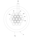
- FIG. 10 is a cross-sectional view showing a cross section of the injection opening body 17, and is a cross-sectional view of the duct 19 along the line C-C in FIG. 9.
- the injection opening body 17 has a tube portion 17a which is a cylindrical member, and a tube portion 17b as a plurality of ducts provided inside the tube portion 17a.
- the tube portion 17a is, for example, a cylindrical or approximately cylindrical member.
- the tube portion 17b is a cylindrical portion extending along the tube portion 17a, and the internal space forms the above-mentioned passage 18.
- the tube portion 17a is accommodated in the hole 19c of the duct 19, and the outer peripheral surface of the tube portion 17a is in contact with the hole 19c.
- the tube portion 17a also protrudes from the hole 19c.
- the passage 18 extends along the pipe portion 17b, opens to the outside of the pipeline 19 at the upper end of the pipe portion 17b, and communicates with the space 12 inside the pipe portion 19 at the lower end of the pipe portion 17b.
- multiple tube sections 17b are provided in the space of the tubular section 17a, and the multiple pipelines 17b are arranged in parallel to one another.
- the passages 18 of each tube section 17b are open to the outside at both ends of the tubular section 17a.
- the multiple tube sections 17b are closely packed within the tubular section 17a, and each of the multiple tube sections 17b is surrounded by other pipelines 17b, and each tube section 17b is in contact with the multiple tube sections 17b it surrounds. Also, for example, the gaps between adjacent tube sections 17b are sealed.
- the tube portion 17b has, for example, a cylindrical or approximately cylindrical shape.
- the diameter D2 (see FIGS. 10 and 11) of the cross section of the passage 18 is set to a value such that the hydrogen gas in the passage 18 is not burned by the hydrogen gas that comes out of the ejection opening body 17 through the passage 18 and burns. As shown in FIGS.
- the diameter D2 of the passage 18 is, for example, the distance (line segment) between the intersection points of a straight line passing through the central axis (center) and the contour line drawn by the inner peripheral surface of the tube portion 17b in a cross section perpendicular to the central axis of the tube portion 17b, and is specifically, for example, the maximum value, minimum value, or average value of the distances of these line segments.
- the diameter D2 of the passage 18 may be other values of the distances of these line segments. In this example, the diameter D2 of the passage 18 is the maximum value of the distances of these line segments.
- the cross-sectional shape of the passage 18 (contour in the cross section) is, for example, circular or approximately circular.
- the diameter D2 of the passage 18 is the diameter of the passage 18 and is the diameter of the inner peripheral surface of the tube portion 17b.
- the diameter D2 of the passage 18 is, for example, smaller than 0.64 mm.
- the hydrogen combustion device 5 has the above-mentioned configuration, and hydrogen gas supplied to the ejection body 16 via the supply pipe 20 can be supplied from the space 12 in the pipe 19 to the passages 18 of the multiple pipe sections 17b of each injection opening body 17.
- the hydrogen gas supplied from the hydrogen tank 3 is not mixed with air until it exits from the injection opening body 17 of the pipe 19.
- the hydrogen gas supplied to the multiple passages 18 is ejected from each passage 18 to the outside of the pipe 19 and mixed with air. Then, the hydrogen gas ejected from the passage 18 can be burned by igniting the hydrogen gas ejected from the passage 18.
- the diameter D2 of the passage 18 from which the hydrogen gas is ejected is set to a value such that the hydrogen gas in the passage 18 is not burned by the hydrogen gas that exits the passage 18 and burns, so the hydrogen gas in the passage 18 is not burned by the burning hydrogen gas. Therefore, when hydrogen gas is ignited or when the burning hydrogen gas is extinguished, the hydrogen gas in the passage 18 of the injection opening body 17 and the hydrogen gas in the space 12 of the pipe 19 do not burn, and when hydrogen gas is ignited or when the burning hydrogen gas is extinguished, the occurrence of so-called backfire can be prevented or suppressed, and the occurrence of abnormal noises, etc. can be prevented or suppressed.
- hydrogen cooking device 6 differs from the above-mentioned hydrogen cooking device 1 in that it has a hydrogen combustion device 5 instead of hydrogen combustion device 1.
- hydrogen combustion device 5 is supported on a receiving stand 50 of support body 4, similar to hydrogen combustion device 1. Therefore, hydrogen cooking device 6 functions in the same way as hydrogen cooking device 2, and can cook food in the same way as hydrogen cooking device 2.
- the hydrogen combustion device 5 and hydrogen cooking device 6 according to the second embodiment of the present invention can be respectively a hydrogen combustion device and a hydrogen cooking device that have been improved taking into account the physical properties of hydrogen.
- the cross-sectional shape of the passage 18 of the injection opening body 17 is not limited to a circle, and may be other shapes.
- the shape of the tube portion 17a of the injection opening body 17 is not limited to a cylindrical shape, and may be other shapes.
- the cross-sectional shape of the passage 18 may be rectangular, and the cross-sectional shape of the tube portion 17a may be rectangular.
- the cross-sectional shapes of the multiple passages 18 do not all have to be the same shape.
- the multiple tube portions 17b can be more closely spaced in each tube portion 17a.
- FIG. 12 the modified example of FIG.
- the diameter D2 of the passage 18 is, for example, the maximum value of the distance of the line segment between the intersection point of the straight line passing through the central axis (center) and the outline drawn by the inner peripheral surface of the tube portion 17b in a cross section perpendicular to the central axis of the tube portion 17b.
- FIG. 13 is a cross-sectional view of the pipe 19 according to the modified example.
- the tube portion 17a of the injection opening body 17 does not have a tube portion 17b, but has a porous body 60.
- the porous body 60 has a plurality of holes 62 therein.
- the holes 62 form minute spaces inside the porous body 60.
- the plurality of holes 62 are connected to form a plurality of passages 61.
- the passages 61 like the above-mentioned passage 18, penetrate the porous body 60 and communicate with the space 12 inside the pipe 19 and the outside of the pipe 19.
- the diameter D2 of the passage 61 is the diameter of the cross section of the passage 61, and the diameter D2 of the passage 61 is set to a value such that the hydrogen gas in the passage 61 does not burn due to the hydrogen gas that comes out of the injection opening body 17 through the passage 61 and burns.
- the diameter D2 of the passage 61 is, for example, the maximum value of the diameter of the passage 61.
- the diameter D2 of the passage 61 is, for example, smaller than 0.64 mm.
- the hydrogen gas supplied from the hydrogen tank 3 is not mixed with air until it exits through the injection opening 17 of the pipe 19.
- the hole 19c is not provided with an injection opening 17, and a porous body 60 is provided in the space 12 of the conduit 19, and the injection opening 17 is formed in the space 12 of the conduit 19 by the porous body 60.
- a porous body may also be provided in the hole 19c.
- the porous body 60 has a plurality of passages 61 in the space 12, each of which is formed by a plurality of holes 62 connected together. The passages 61 penetrate the porous body 60, and a plurality of passages 61 are formed in the space 12 in the conduit 19, extending between the end 19a of the conduit 19 and the hole 19c.
- the passages 61 allow the hydrogen gas supplied to the ejection body 16 to be supplied to the passages 61 in the porous body 60 via the buffer conduit 14, and to pass through the passages 61 and exit the conduit 19 from the hole 19c.
- the diameter D2 of the passage 61 is the cross-sectional diameter of the passage 61, similar to the diameter of the passage 18, and is set to a value such that the hydrogen gas in the passage 61 is not burned by the hydrogen gas that comes out of the hole 19c of the pipe 19 through the passage 61 and burns.
- the diameter D2 of the passage 61 is, for example, the maximum value of the diameter of the passage 61.
- the diameter D2 of the passage 61 is, for example, smaller than 0.64 mm.
- the configuration of the ejection body 16 is adjusted so that gas comes out uniformly from each of the ejection opening bodies 17 of the multiple holes 19c (see FIG. 9) or from each of the multiple holes 19c (see FIG. 14).
- the configuration of the ejection body 16 that is adjusted is, for example, the diameter D2 of each passage 18, 61.
- the configuration of the ejection body 16 is adjusted so that gas comes out uniformly or approximately uniformly from the ejection opening bodies 17 or holes 19c of all holes 19c of the ejection body 16.
- the configuration of the ejection body 16 is adjusted so that gas comes out uniformly or approximately uniformly from the ejection opening bodies 17 or holes 19c of all holes 19c of each pipe 19 of the ejection body 16.
- the configuration of the ejection body 16 that is adjusted so that gas comes out uniformly or approximately uniformly is, for example, the diameter D2 of each passage 18, 61, the length of the space 12 in each pipe 19, the diameter (flow path cross-sectional area) of the space 12 in each pipe 19, the length of the space 15 in the buffer pipe 14, and the diameter (flow path cross-sectional area) of the space 15 in the buffer pipe 14. Any one or any combination of these configurations of the ejection body 16 is adjusted for uniform or approximately uniform gas ejection.
- the hydrogen gas supplied from the hydrogen tank 3 is not mixed with air until it exits through the hole 19c in the pipe 19 or the porous body 60 (injection opening body 17).
- the shape of the conduits 11, 19 in the ejecting bodies 10, 16, respectively is not limited to extending along a straight line, and for example, the conduits 11, 19 may extend in a ring shape.
- the conduit 11 extending from the buffer conduit 14 may be a conduit 70 having a ring portion 71, which is a portion extending in a ring shape, and a connection portion 72, which is a portion extending between the ring portion 71 and the buffer conduit 14.
- the ring portion 71 has a configuration similar to that of the pipeline 11, forms an annular space 12, and has a plurality of open holes 13.
- the ring portion 71 is an endless ring, and extends, for example, in a ring shape that extends along a circle or an approximately circle. That is, the space 12 extends in an endless ring shape, and extends, for example, in a ring shape that extends along a circle or an approximately circle.
- the ring portion 71 may be an annular shape with ends.
- the connection portion 72 forms the space 12 like the pipeline 11, and has a valve 11c that allows the space 12 to be closed.
- connection portion 72 does not have an open hole 13, and is connected to the space 12 of the ring portion 71 at one end, and is connected to the space 15 of the buffer pipeline 14 at the other end.
- the connection portion 72 has two parts, part 72a and part 72b, as shown in FIG. 15, for example.
- Part 72a is the part that is connected to the buffer pipe 14 of the connection part 72
- part 72b is the part that positions the ring part 71 above part 72a, and extends upward from the end of part 72a.
- Parts 72a and 72b of the connection part 72 may each extend along a straight line, a curved line, a line that is a combination of a straight line and a straight line, or a line that is a combination of a curved line and a straight line, or may extend in various shapes.
- a plurality of through holes 13 are formed in the ring portion 71.
- the plurality of through holes 13 are arranged in a row in the circumferential direction, for example, on a circle or an approximately circle at equal or approximately equal angular intervals.
- the plurality of through holes 13 may also be arranged in a plurality of annular rows on the inner and outer circumferential sides. For example, as shown in FIG. 15, the plurality of through holes 13 are arranged in two annular rows.
- the plurality of through holes 13 are arranged in a row on a small diameter circle or an approximately circle on the inner circumferential side at equal or approximately equal angular intervals, and are arranged in a row on a large diameter circle or an approximately circle on the outer circumferential side at equal or approximately equal angular intervals.
- the plurality of through holes 13 may also be arranged in a single annular row.
- the plurality of through holes 13 may also be arranged without forming a row in the circumferential direction.
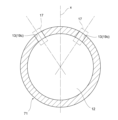
- FIG. 16 is a cross-sectional view taken along line D-D in FIG. 15, and is a cross-sectional view taken along a plane perpendicular to the extension direction of the ring portion 71.
- the inner peripheral side through hole 13 and the outer peripheral side through hole 13 that are adjacent to each other form pairs and are aligned in the radial direction.
- the inner peripheral side through hole 13 and the outer peripheral side through hole 13 that are adjacent to each other are positioned on the same or approximately the same straight line extending in the radial direction.
- the inner peripheral side through hole 13 and the outer peripheral side through hole 13 do not have to be aligned in the radial direction.
- the multiple through holes 13 that form the inner peripheral side row and the multiple through holes 13 that form the outer peripheral side row are each offset in the circumferential direction by a predetermined interval.
- the through hole 13 on the inner circumference side extends at an inclination toward the inner circumference side with respect to the orthogonal axis x
- the through hole 13 on the outer circumference side extends at an inclination toward the outer circumference side with respect to the orthogonal axis x.
- the orthogonal axis x is a line extending in the vertical direction passing through the center or approximately the center of a cross section taken along a plane perpendicular to the extension direction of the ring portion 71 or the space 12.
- the inclination angle of the through hole 13 on the inner circumference side with respect to the axis x and the inclination angle of the through hole 13 on the outer circumference side with respect to the axis x are the same or approximately the same.
- the inclination angle of the through hole 13 on the inner circumference side with respect to the axis x and the inclination angle of the through hole 13 on the outer circumference side with respect to the axis x may be different.
- the pipe 70 can make the ejection velocity V of the hydrogen gas coming out of the open hole 13 greater than the combustion velocity Vh of the hydrogen gas, and acts in the same way as the above-mentioned pipe 11.
- a gap is formed between the rings 71A and 71B, and a gap is formed between the rings 71B and 71C, and the radial width of the gap between the rings 71A and 71B and the radial width of the gap between the rings 71B and 71C are the same or approximately the same. Note that the radial width of the gap between the rings 71A and 71B and the radial width of the gap between the rings 71B and 71C may be different from each other.
- 72A which is the connection part 72 of the pipeline 70A
- 72B which is the connection part 72 of the pipeline 70B
- 72C which is the connection part 72 of the pipeline 70C
- FIG. 18 is a perspective view showing an example of a hydrogen combustion device 1, 5 provided with an ejection body 10, 19 having the above-mentioned duct 70.
- the storage table 50 of the hydrogen combustion device 1, 5 has a circular opening 54, and a mounting table 55 is fixed to the edge of the opening 54.
- the mounting table 55 has multiple legs 55a, such as a trivet, and cooking objects can be placed directly or indirectly on the multiple legs 55a.
- the ejection body 10, 19 is disposed in the storage space 52, and the rings 71 of the multiple ducts 70 are exposed through the opening 54 when viewed from above.
- the above-described embodiments are intended to facilitate understanding of the present invention, and are not intended to limit the present invention. Furthermore, the above-described embodiments do not limit the use of the present invention, and the present invention may include anything as its use.
- the components of the above-described embodiments, as well as their arrangement, materials, conditions, shape, size, etc., are not limited to those exemplified, and may be modified as appropriate.
- the present invention includes differences that arise in implementation due to manufacturing tolerances, etc.
- the components shown in different embodiments may be partially substituted or combined to the extent that there is no technical contradiction.
- the configurations may be selectively combined as appropriate to achieve at least some of the above-described problems and effects.
- the gas supplied to the ejection bodies 10 and 16 may not be pure hydrogen gas, but may be mixed hydrogen gas in which other gases such as air are mixed with pure hydrogen gas, and in this case, the characteristics of the hydrogen gas according to the present invention may be the characteristics of the mixed hydrogen gas rather than the characteristics of hydrogen gas.
- the burning speed of the hydrogen gas according to the present invention may be the burning speed of the mixed hydrogen gas
- the ejection flow speed of the mixed hydrogen gas emerging from the open hole 13 may be greater than the burning speed of the mixed hydrogen gas.
- the quenching distance of the hydrogen gas may be the quenching distance of the mixed hydrogen gas.
Landscapes
- Engineering & Computer Science (AREA)
- Chemical & Material Sciences (AREA)
- Combustion & Propulsion (AREA)
- Mechanical Engineering (AREA)
- General Engineering & Computer Science (AREA)
- Feeding And Controlling Fuel (AREA)
Priority Applications (1)
| Application Number | Priority Date | Filing Date | Title |
|---|---|---|---|
| JP2025520475A JPWO2024237030A1 (https=) | 2023-05-17 | 2024-04-22 |
Applications Claiming Priority (2)
| Application Number | Priority Date | Filing Date | Title |
|---|---|---|---|
| JP2023-081726 | 2023-05-17 | ||
| JP2023081726 | 2023-05-17 |
Publications (1)
| Publication Number | Publication Date |
|---|---|
| WO2024237030A1 true WO2024237030A1 (ja) | 2024-11-21 |
Family
ID=93519027
Family Applications (1)
| Application Number | Title | Priority Date | Filing Date |
|---|---|---|---|
| PCT/JP2024/015788 Ceased WO2024237030A1 (ja) | 2023-05-17 | 2024-04-22 | 水素燃焼装置及び水素調理装置 |
Country Status (2)
| Country | Link |
|---|---|
| JP (1) | JPWO2024237030A1 (https=) |
| WO (1) | WO2024237030A1 (https=) |
Citations (8)
| Publication number | Priority date | Publication date | Assignee | Title |
|---|---|---|---|---|
| JPH05139887A (ja) * | 1990-07-06 | 1993-06-08 | Toyota Central Res & Dev Lab Inc | ダイヤモンド膜生成方法およびその装置 |
| JPH1047681A (ja) * | 1996-07-29 | 1998-02-20 | Paloma Ind Ltd | ガスこんろ |
| JPH10185124A (ja) * | 1996-12-20 | 1998-07-14 | Iwatani Internatl Corp | 筒形ガスバーナ |
| JP2002106825A (ja) * | 2000-10-02 | 2002-04-10 | Ebara Corp | 燃焼式排ガス処理装置 |
| WO2007021053A1 (en) * | 2005-08-17 | 2007-02-22 | Daum Energy Co., Ltd. | Hydrogen burner and heat supply system using the same |
| JP2012042068A (ja) * | 2010-08-13 | 2012-03-01 | Yasuo Ishikawa | 水素調理装置 |
| JP2014223046A (ja) * | 2012-12-13 | 2014-12-04 | 株式会社Ti | 水素調理方法、水素調理システム、水素水製造方法、水素水製造装置及び水素調理装置 |
| JP2016090141A (ja) * | 2014-11-05 | 2016-05-23 | 川崎重工業株式会社 | バーナ、燃焼器、及びガスタービン |
-
2024
- 2024-04-22 JP JP2025520475A patent/JPWO2024237030A1/ja active Pending
- 2024-04-22 WO PCT/JP2024/015788 patent/WO2024237030A1/ja not_active Ceased
Patent Citations (8)
| Publication number | Priority date | Publication date | Assignee | Title |
|---|---|---|---|---|
| JPH05139887A (ja) * | 1990-07-06 | 1993-06-08 | Toyota Central Res & Dev Lab Inc | ダイヤモンド膜生成方法およびその装置 |
| JPH1047681A (ja) * | 1996-07-29 | 1998-02-20 | Paloma Ind Ltd | ガスこんろ |
| JPH10185124A (ja) * | 1996-12-20 | 1998-07-14 | Iwatani Internatl Corp | 筒形ガスバーナ |
| JP2002106825A (ja) * | 2000-10-02 | 2002-04-10 | Ebara Corp | 燃焼式排ガス処理装置 |
| WO2007021053A1 (en) * | 2005-08-17 | 2007-02-22 | Daum Energy Co., Ltd. | Hydrogen burner and heat supply system using the same |
| JP2012042068A (ja) * | 2010-08-13 | 2012-03-01 | Yasuo Ishikawa | 水素調理装置 |
| JP2014223046A (ja) * | 2012-12-13 | 2014-12-04 | 株式会社Ti | 水素調理方法、水素調理システム、水素水製造方法、水素水製造装置及び水素調理装置 |
| JP2016090141A (ja) * | 2014-11-05 | 2016-05-23 | 川崎重工業株式会社 | バーナ、燃焼器、及びガスタービン |
Also Published As
| Publication number | Publication date |
|---|---|
| JPWO2024237030A1 (https=) | 2024-11-21 |
Similar Documents
| Publication | Publication Date | Title |
|---|---|---|
| EP3333481B1 (en) | Hydrogen gas burner structure, and hydrogen gas burner device including the same | |
| JPS6222726Y2 (https=) | ||
| JP4930921B2 (ja) | ガスタービンエンジンの燃焼室のための燃料インジェクタ | |
| JP7064474B2 (ja) | 混焼バーナー | |
| US7591648B2 (en) | Burner apparatus | |
| JP2008116195A (ja) | 部分的に予混合式のフレアバーナ及びその方法 | |
| JP6906881B1 (ja) | 低燃焼性燃料燃焼装置 | |
| CN102052673A (zh) | 降低进入多喷嘴装置的流量分配不均的燃烧器头端导叶 | |
| US9835335B2 (en) | Air directed fuel injection | |
| CN104870901B (zh) | 凹入式燃料喷射器的布置 | |
| JP2010181142A (ja) | ガスタービンエンジン内で使用するための燃焼器アセンブリおよび燃焼器アセンブリを組み立てる方法 | |
| JP5997440B2 (ja) | ペグなし二次燃料ノズル | |
| US9810427B2 (en) | Fuel nozzle with hemispherical dome air inlet | |
| CN107246611B (zh) | 燃气燃烧器 | |
| JP2015169357A (ja) | 水中燃焼式気化装置 | |
| WO2024237030A1 (ja) | 水素燃焼装置及び水素調理装置 | |
| US4311452A (en) | High stability gas/electric pilot-ignitor | |
| JP5636335B2 (ja) | ガスタービン燃焼器 | |
| JPH09189407A (ja) | バーナ | |
| JP3817625B2 (ja) | バーナ装置 | |
| EP3714208B1 (en) | Radiant wall burner | |
| JP2023106203A (ja) | バーナー | |
| JP7548020B2 (ja) | バーナ | |
| JP2023154262A (ja) | バーナ | |
| WO2022208968A1 (ja) | ガスバーナ及びボイラ |
Legal Events
| Date | Code | Title | Description |
|---|---|---|---|
| 121 | Ep: the epo has been informed by wipo that ep was designated in this application |
Ref document number: 24806984 Country of ref document: EP Kind code of ref document: A1 |
|
| ENP | Entry into the national phase |
Ref document number: 2025520475 Country of ref document: JP Kind code of ref document: A |
|
| WWE | Wipo information: entry into national phase |
Ref document number: 2025520475 Country of ref document: JP |
|
| NENP | Non-entry into the national phase |
Ref country code: DE |