WO2024236643A1 - モード局在センサ、モード局在センサを用いた機器、および物理量検出方法 - Google Patents
モード局在センサ、モード局在センサを用いた機器、および物理量検出方法 Download PDFInfo
- Publication number
- WO2024236643A1 WO2024236643A1 PCT/JP2023/017934 JP2023017934W WO2024236643A1 WO 2024236643 A1 WO2024236643 A1 WO 2024236643A1 JP 2023017934 W JP2023017934 W JP 2023017934W WO 2024236643 A1 WO2024236643 A1 WO 2024236643A1
- Authority
- WO
- WIPO (PCT)
- Prior art keywords
- phase
- mode
- component
- mode component
- amplitude
- Prior art date
- Legal status (The legal status is an assumption and is not a legal conclusion. Google has not performed a legal analysis and makes no representation as to the accuracy of the status listed.)
- Ceased
Links
Classifications
-
- G—PHYSICS
- G01—MEASURING; TESTING
- G01P—MEASURING LINEAR OR ANGULAR SPEED, ACCELERATION, DECELERATION, OR SHOCK; INDICATING PRESENCE, ABSENCE, OR DIRECTION, OF MOVEMENT
- G01P15/00—Measuring acceleration; Measuring deceleration; Measuring shock, i.e. sudden change of acceleration
- G01P15/02—Measuring acceleration; Measuring deceleration; Measuring shock, i.e. sudden change of acceleration by making use of inertia forces using solid seismic masses
- G01P15/08—Measuring acceleration; Measuring deceleration; Measuring shock, i.e. sudden change of acceleration by making use of inertia forces using solid seismic masses with conversion into electric or magnetic values
- G01P15/097—Measuring acceleration; Measuring deceleration; Measuring shock, i.e. sudden change of acceleration by making use of inertia forces using solid seismic masses with conversion into electric or magnetic values by vibratory elements
Definitions
- the present invention relates to a mode localization sensor, an apparatus using the mode localization sensor, and a method for detecting a physical quantity.
- mode localization sensors are vibration systems with multiple degrees of freedom, multiple vibration modes may coexist and interfere with each other.
- a method has been proposed that reduces either the in-phase mode component (IP; In-Phase) or the anti-phase mode component (AP; Anti-Phase) (see, for example, Patent Document 1).
- IP in-phase mode component
- AP anti-phase mode component
- Patent Document 1 a method has been developed in which an anchor support is provided in the middle of the connecting part to weaken the mechanical connection between the two vibrators (see, for example, Non-Patent Document 1), or the mode shape is changed by using the perturbation generated in the two outer vibrating parts by dividing the vibrating parts into three (see, for example, Non-Patent Documents 2 and 3).
- the present invention was made in consideration of these problems, and aims to provide a mode localization sensor that can increase sensitivity and further reduce noise, an apparatus using a mode localization sensor, and a physical quantity detection method.
- the mode localization sensor is characterized by having a multi-degree-of-freedom vibration system, a mode separation means for separating the in-phase and anti-phase mode components of a detection signal based on the vibration of the multi-degree-of-freedom vibration system using a reference signal, and a detection means configured to detect a change in the asymmetry of the stiffness of the multi-degree-of-freedom vibration system based on the in-phase and anti-phase mode components separated by the mode separation means, and to determine a change in a predetermined physical quantity based on the change.
- the device according to the present invention uses the mode localization sensor according to the present invention.
- the physical quantity detection method is characterized by having a mode separation step in which, using a reference signal, the in-phase mode component and the anti-phase mode component of a detection signal based on the vibration of a multi-degree-of-freedom vibration system are separated, and a detection step in which, based on the in-phase mode component and the anti-phase mode component separated by the mode separation step, a change in the asymmetry of the stiffness of the multi-degree-of-freedom vibration system is detected, and a change in a predetermined physical quantity is determined based on the change.
- the present invention provides a mode localization sensor that can further increase sensitivity and reduce noise, an apparatus using the mode localization sensor, and a physical quantity detection method.
- 1A and 1B are a plan view and a principle diagram showing a MEMS resonator of a mode localization sensor according to an embodiment of the present invention, respectively;
- FIG. 1 is a block diagram showing a mode localization sensor according to an embodiment of the present invention
- 1 is a diagram illustrating the principle of mode separation in a mode localization sensor according to an embodiment of the present invention
- 1 is a circuit diagram showing a mode localization sensor according to an embodiment of the present invention.
- FIG. 1A is an explanatory diagram showing that the displacement x1 of the first vibration part and the displacement x2 of the second vibration part are composed of an overlap of an in-phase mode component IP and an opposite-phase mode component AP of the mode localization sensor according to the embodiment of the present invention;
- FIG. 1A is an explanatory diagram showing that the displacement x1 of the first vibration part and the displacement x2 of the second vibration part are composed of an overlap of an in-phase mode component IP and an opposite-phase mode component AP of the mode localization sensor according to the embodiment of the present invention;
- FIG. 1A is an explanatory diagram showing that the displacement x1 of the first vibration part and the displacement x2 of the second vibration
- FIG. 1B is an explanatory diagram showing a method for converting the displacement x1 of the first vibration part and the displacement x2 of the second vibration part into an in-phase mode component IP and an opposite-phase mode component AP.
- FIG. 11 is a circuit diagram for explaining the reason why interference occurs between the common-mode component generated in the common-mode control loop and the common-mode component generated in the anti-phase control loop on the common-mode component side of the mode localization sensor according to the embodiment of the present invention.
- 11 is a graph showing (a) the change in amplitude of the in-phase mode component (IP) and the anti-phase mode component (AP) of the output from the in-phase side mode separator versus frequency, (b) the change in phase, (c) the change in amplitude of the in-phase mode component (IP) and the anti-phase mode component (AP) of the output from the anti-phase side mode separator versus frequency, and (d) the change in phase, of the simulation results shown in FIG.
- Figure 1 shows an example of a mode localization type MEMS vibrator 11.
- the mode localization sensor of the present invention can also be applied to three-mass systems, systems with a greater number of masses, two-axis vibrators, and multi-degree-of-freedom vibration systems that undergo continuous deformation.
- a three-mass system or a system that undergoes continuous deformation can be expressed as a two-mass vibrator as shown in Figure 1, and therefore can be applied to the mode localization sensor of the present invention.
- the MEMS vibrator 11 shown in Figure 1 is not limited to MEMS, and may be a general vibrator.
- the two-mass MEMS vibrator 11 has a support section, a first vibrating section and a second vibrating section that are arranged to vibrate in a predetermined direction relative to the support section, a first connecting section having a first spring constant and connecting the support section to the first vibrating section, a second connecting section having a second spring constant and connecting the support section to the second vibrating section, and a connecting section having a third spring constant and connecting the first vibrating section to the second vibrating section.
- the mode localized MEMS vibrator 11 has an external frame 20, support parts 21a and 21b, a first vibrating part 22, a second vibrating part 23, a first connecting part 24, a second connecting part 25, and a linking part 26.
- the MEMS vibrator 11 is manufactured by MEMS technology using an SOI (Silicon on Insulator) wafer. Each part of the MEMS vibrator 11 is formed by photolithography and etching.
- the first vibrating part 22 (mass m 1 ) and the second vibrating part 23 (mass m 2 ) are formed side by side at a distance in the center of the SOI wafer.
- the linking part 26 is formed between the first vibrating part 22 and the second vibrating part 23 so as to link the first vibrating part 22 and the second vibrating part 23.
- the first vibrating part 22 and the second vibrating part 23 have approximately the same mass.
- the external frame 20 is formed with a gap between the first vibration part 22 and the second vibration part 23 so as to surround the periphery of the first vibration part 22 and the second vibration part 23.
- the support parts 21a and 21b are made up of eight pieces, and are provided at the four corners of the first vibration part 22 and the second vibration part 23, respectively, and are fixed to the external frame 20.
- the first connection parts 24 are formed at the four corners of the first vibration part 22 so as to connect the corresponding support parts 21a to the first vibration part 22, and the second connection parts 25 are formed at the four corners of the second vibration part 23 so as to connect the corresponding support parts 21b to the second vibration part 23.
- the four first connection parts 24 have a first spring constant k1
- the four second connection parts 25 have a second spring constant k2
- the linking part 26 has a third spring constant kc . 1 relative to the external frame 20.
- the mode localization sensor of the present invention can be realized regardless of the physical shape as long as the basic structure includes a vibrator that can be modeled as shown in Figure 1 in generalized coordinate display (modal coordinate display).
- the difference ⁇ k between the first spring constant k1 and the second spring constant k2 of the in-phase mode component can be obtained.
- ⁇ k can be obtained similarly by using formula (2).
- a more accurate ⁇ k can be obtained by, for example, calculating an average value using ⁇ k calculated from the in-phase mode component and ⁇ k calculated from the anti-phase mode component.
- ⁇ k when ⁇ k changes slightly, the value of x2 / x1 of the in-phase mode component and/or the anti-phase mode component of the first vibrating part and the second vibrating part changes significantly.
- the mode localization sensor according to the present invention can use the region in which the amplitude ratio in FIG. 2 is close to 1 by separating the in-phase mode and the anti-phase mode in a method completely different from the conventional methods.
- the mode localization sensor according to the present invention can obtain twice as much information as the conventional information from only one of the modes, and therefore it is expected that the sensitivity will be equal to or higher than that of the conventional one.
- the resonant frequency can also be measured, so that a high-speed response can be expected.
- the mode localization sensor according to the present invention can obtain the change in the value of the mode shape x2 / x1 due to the change in ⁇ k, independently in the in-phase mode and the anti-phase mode.
- the mode localization sensor according to the present invention may be configured to detect the difference between these detected values and the spring constant.
- the vibration modes are separated using a reference signal.
- the separation is performed based on the orthogonality between the eigenmode components. Since the in-phase mode component and the anti-phase mode component are mutually orthogonal, the inner product of the in-phase mode component signal and the anti-phase mode component signal is zero. On the other hand, the inner product of the in-phase mode components and the anti-phase mode components can be used to know the magnitude of the mode components. Therefore, the mode localization sensor according to the present invention can extract only the signal component of the in-phase mode component by calculating the inner product of the detection signal, in which the in-phase mode component and the anti-phase mode component are mixed, and the reference signal of the in-phase mode component.
- the mode localization sensor of the present invention can detect changes in the asymmetry of the stiffness of a multi-degree-of-freedom vibration system, such as the difference between a first spring constant and a second spring constant, by using both the in-phase mode component and the anti-phase mode component separated by the mode separation means, and therefore can improve sensitivity compared to using only one of them. Furthermore, since the in-phase mode component and the anti-phase mode component can be separated by the mode separation means to prevent other mode components from being mixed in, even if the frequencies of each mode component become closer as a result of increased sensitivity, interference between modes can be suppressed and control can be achieved. As a result, it becomes possible to operate in a region where the amplitudes of each mass are of equal magnitude, and noise can be further reduced.
- Mode localization sensor In the mode localized MEMS vibrator 11, an in-phase mode and an anti-phase mode are mixed. In the mode localization sensor according to the embodiment of the present invention, the in-phase mode and the anti-phase mode are separated from each other by using the mode separation means 12 shown in FIG.
- the mode localization sensor 10 has the MEMS vibrator 11 shown in Figure 1, a mode separation means 12 that separates modes from the MEMS vibrator 11, a driving means 13 that drives the MEMS vibrator 11, and a detection means 14 that detects the in-phase mode component and the anti-phase mode component of the MEMS vibrator 11 separated by the mode separation means.
- the mode separation means 12 has a mode separator 31 and a resonant control circuit 32 consisting of a phase-locked loop (PLL) circuit and an automatic gain control (AGC).
- the phase-locked loop may be a phase shifter.
- the mode separator 31 is configured to separate the in-phase mode components and the anti-phase mode components from the displacements of the first vibration part 22 and the second vibration part 23 of the MEMS vibrator 11. More specifically, as shown in FIG. 5, the mode separator 31 is composed of an anti-phase side mode separator 31a that separates the anti-phase mode components, and an in-phase side mode separator 31b that separates the in-phase mode components.
- the specific function of the mode separator 31 is to separate the in-phase mode components and the anti-phase mode components by utilizing the fact that the inner product of the in-phase mode components and the anti-phase mode components is zero due to the orthogonality of each mode component (the inner product of the anti-phase mode components and the inner product of the in-phase mode components is 1).
- the mode separator 31 is configured to use an antiphase reference signal of an antiphase mode based on the vibration of the first vibrating part 22 and the second vibrating part 23 when the MEMS vibrator 11 resonates in antiphase, and to take the inner product of the detection signal consisting of the vibration of the first vibrating part 22 and the second vibrating part 23 in which the inphase mode component and the antiphase mode component are combined, and to separate the antiphase mode component by making the inphase mode component zero.
- the antiphase reference signal an antiphase mode as a reference and an antiphase mode shifted in phase by 90 degrees from the antiphase mode are used.
- the mode separator 31 is configured to use an inphase reference signal based on the vibration of the first vibrating part 22 and the second vibrating part 23 when they resonate in phase, and to take the inner product of the detection signal consisting of the vibration of the first vibrating part 22 and the second vibrating part 23, and to separate the inphase mode component by making the antiphase mode component zero.
- the in-phase reference signal uses a reference in-phase mode and an in-phase mode that is 90 degrees out of phase with the reference in-phase mode.
- the in-phase reference signal and the anti-phase reference signal are synthesized in the resonance control circuit 32 using the in-phase mode components and the anti-phase mode components separated by the mode separator 31.
- the in-phase reference signal and the anti-phase reference signal may be synthesized in advance.
- the resonance control circuit 32 is configured to convert the in-phase mode components and the anti-phase mode components separated by the mode separator 31 into an in-phase reference signal and an anti-phase reference signal, respectively, and feed them back to the mode separator 31.
- the resonant control circuit 32 has numerically controlled oscillators (NCOs) 41a, 41b and proportional integral controllers (PIs) 42a, 42b, and is configured to form an in-phase reference signal based on the phase of the in-phase mode component separated by the in-phase side mode separator 31b, and to form an anti-phase reference signal based on the phase of the anti-phase mode component separated by the anti-phase side mode separator 31a.
- NCOs numerically controlled oscillators
- PIs proportional integral controllers
- the resonance control circuit 32 is configured to send a signal of the phase of the antiphase mode component separated by the antiphase side mode separator 31a to the NCO 41a via the PI 42a, synthesize two antiphase reference signals with a phase shift of 90 degrees, and feed back the signal to the antiphase side mode separator 31a.
- the resonance control circuit 32 is configured to send a signal of the phase of the in-phase mode component separated by the in-phase side mode separator 31b to the NCO 41b via the PI 42b, synthesize two in-phase reference signals with a phase shift of 90 degrees, and feed back the signal to the in-phase side mode separator 31b. This controls the phase difference between each reference signal and the vibration signal to a constant value (phase-locked loop), and each mode is resonantly driven.
- the driving means 13 is configured to drive the first vibrating section 22 and the second vibrating section 23 with an in-phase drive signal that resonates in phase with each other and an anti-phase drive signal that resonates in anti-phase with each other in order to control the two in-phase and anti-phase modes of the MEMS vibrator 11.
- the in-phase drive signal consists of a signal formed based on the amplitude and phase of the in-phase mode component separated by the mode separation means 12
- the anti-phase reference signal consists of a signal formed based on the amplitude and phase of the anti-phase mode component separated by the mode separation means 12.
- the in-phase drive signal and the anti-phase drive signal may be synthesized in advance.
- the driving means 13 has proportional-integral controllers (PI) 43a, 43b, and is configured to form an antiphase drive signal by passing the amplitude signal of the antiphase mode component separated by the antiphase side mode separator 31a through the PI 43a and then combining it with the antiphase reference signal (not out of phase by 90 degrees) output from the NCO 41a.
- the driving means 13 is configured to form an inphase drive signal by passing the amplitude signal of the inphase mode component separated by the inphase side mode separator 31b through the PI 43b and then combining it with the inphase reference signal (not out of phase by 90 degrees) output from the NCO 41b.
- the driving means 13 is configured to drive one of the first vibration section 22 and the second vibration section 23 of the MEMS vibrator 11 with a signal obtained by combining the formed anti-phase drive signal and the in-phase drive signal, and to drive the other of the first vibration section 22 and the second vibration section 23 with a signal obtained by combining a signal obtained by inverting the amplitude of the anti-phase drive signal and the in-phase drive signal.
- This allows automatic gain control to be performed, in which the amplitude of each mode is controlled to a constant value.
- the mode localization sensor 10 generates the initial reference signals by making the signs of the drive signals generated by the NCO 41a and NCO 41b of the resonance control circuit 32 the same (in-phase) while keeping the amplitude the same, or by making the signs opposite (out-of-phase).
- the detection means 14 is configured to detect a change in the asymmetry of the stiffness of the MEMS vibrator 11, i.e., the difference between the first spring constant and the second spring constant, based on the in-phase mode component and the anti-phase mode component separated by the mode separator 31.
- the detection means 14 is also configured to determine a change in a predetermined physical quantity, such as acceleration, angular velocity, or angular acceleration, based on the change in the detected difference between the first spring constant and the second spring constant.
- the predetermined physical quantity may be any physical quantity, such as acceleration, angular velocity, angular acceleration, magnetic field, or electric charge, as long as the change in the physical quantity changes the first spring constant and/or the second spring constant.
- the detection means 14 may, if necessary, use not only the shape of each mode component but also the frequency of each mode component to determine the difference in spring constants and a predetermined physical quantity.
- the detection means 14 may also be configured to detect a change in stiffness asymmetry based on the ratio of the amplitudes of two representative points of the in-phase mode component and the ratio of the amplitudes of two representative points of the anti-phase mode component.
- the representative point is the amplitude of a certain point on the MEMS vibrator 11, or the position of a mass point when expressed in generalized coordinates.
- the mode localization sensor 10 can measure a predetermined physical quantity from a state in which the first vibrating part 22 and the second vibrating part 23 are driven (vibrated) by the driving means 13. That is, when a change in the asymmetry of the rigidity of the MEMS vibrator 11 occurs, specifically, when a change in a predetermined physical quantity occurs that changes the first spring constant and/or the second spring constant, the mode separation means 12 separates an in-phase mode component and an anti-phase mode component from the detection signal accompanying the vibration of the first vibrating part 22 and the second vibrating part 23 by using an in-phase reference signal and an anti-phase reference signal.
- the phases of the in-phase mode component and the anti-phase mode component separated by the mode separation means 12 are fed back to synthesize the in-phase reference signal and the anti-phase reference signal, so that the mode separation means 12 can be configured with a relatively simple circuit configuration.
- the in-phase mode component and the anti-phase mode component can be separated relatively easily.
- each mode component can always be kept in a resonant state even if the spring constant changes.
- the amplitude can be controlled by an automatic gain control loop as necessary.
- the detection means 14 can detect the difference ⁇ k between the first spring constant and the second spring constant based on the in-phase mode component and the out-of-phase mode component.
- the change in ⁇ k can be found by determining ⁇ k before and after the physical quantity changes, and the change in the specified physical quantity can be found.
- the inventors discovered a method to express any vibration of the MEMS vibrator 11 as an in-phase mode component IP and an out-of-phase mode component AP, and investigated determining the amplitude ratio by separating IP/AP.
- FIG. 6 shows a method of converting any vibration of the MEMS vibrator 11, where the displacement of the first vibrating part 22 is x1 and the displacement of the second vibrating part 23 is x2 , by assuming that each is composed of an overlap of an in-phase mode component IP and an anti-phase mode component AP. If the amplitude of the in-phase mode component separated by the anti-phase side mode separator 31a and the in-phase side mode separator 31b is AIP and the amplitude of the anti-phase mode component is AAP, x1 and x2 in each mode are expressed by the following relational equation using AIP and AAP .
- the displacement of the first vibrating part 22 in the in-phase mode is x1 ,IP
- the displacement of the second vibrating part 23 is x2 ,IP
- the displacement of the first vibrating part 22 in the reversed-phase mode is x1 ,AP
- the displacement of the second vibrating part 23 is x2 ,AP
- the amplitude of the in-phase mode component separated by the in-phase side mode separator 31b is AIP,IP
- the amplitude of the reversed-phase mode component is AIP,AP
- the amplitude of the in-phase mode component separated by the reversed-phase side mode separator 31a is AAP,IP
- the amplitude of the reversed-phase mode component is AAP,AP
- rIP x2,IP / x1 ,IP
- rAP x2,AP / x1 ,AP
- each mode shape r IP and r AP can be found, and further, the difference ⁇ k between the first spring constant k 1 and the second spring constant k 2 can be found from equations (1), (2), etc. Similarly, ⁇ k can also be found using equations (8) and (9).
- ⁇ Mode Interference> When ⁇ k is not 0, the shape of the eigenmode deviates from 1 and ⁇ 1 due to the asymmetry of the stiffness of the MEMS vibrator 11. If the asymmetric in-phase and anti-phase vibration mode shapes are expressed as mode shapes of ⁇ 1, anti-phase mode vibration occurs in the in-phase mode drive, or in-phase mode vibration occurs in the anti-phase mode drive. Therefore, the in-phase detection signal of the in-phase control loop is affected by the vibration component controlled in the in-phase mode, as well as the in-phase mode signal (see formula (7)) generated in the anti-phase control loop.
- FIG. 7 shows an example of the in-phase side mode separator 31b.
- the in-phase mode signal generated in the anti-phase control loop is also introduced. A method for determining the change in physical quantity while eliminating such modal interference will be described below.
- a mechanism can be added that detects the amplitudes of the in-phase and out-of-phase reference signals in the resonance control circuit 32 and uses a feedback circuit to ensure that ⁇ k is always 0. This allows the mode separator 31 to separate the in-phase and out-of-phase modes, and to separate the amplitudes of each.
- the in-phase mode signal generated in the anti-phase control loop is also introduced. Therefore, in the mode localization sensor 10 equipped with the mode separation means 12 of the present invention, the in-phase mode component generated in the anti-phase mode, that is, the mode shape rAP expressed by the formulas (5) and (7) is obtained by synchronously detecting the in-phase signal component of the in-phase control loop with ⁇ f, and ⁇ k can be obtained from this rAP .
- the amplitude of the in-phase mode component separated by the in-phase side mode separator 31b is essentially a constant value A 0 (hereinafter sometimes referred to as the "basic amplitude").
- a 0 hereinafter sometimes referred to as the "basic amplitude"
- the in-phase mode component generated in the anti-phase control loop enters and interferes with the in-phase mode component, so that the amplitude of the in-phase mode component oscillates around A 0.
- the magnitude of the amplitude A 1 of this oscillation corresponds to the magnitude of the amplitude of the interfering anti-phase mode component, and the period is determined by the difference in the resonant frequencies of the in-phase mode component and the anti-phase mode component.
- the anti-phase amplitude of the anti-phase control loop is also modulated by the anti-phase component generated in the in-phase control loop if ⁇ k is not 0.
- the mode shape r IP and ⁇ k can be obtained by demodulating this signal.
- the mode localization sensor 10 can resonantly drive each of the in-phase and out-of-phase mode components separated by the mode separation means 12.
- the difference between the first spring constant and the second spring constant can be detected using both pieces of information, making it possible to increase sensitivity compared to using only one of them.
- the amplitudes of both masses can be made approximately the same because each mode can be separated, making it possible to suppress an increase in noise associated with displacement measurement.
- the detection means 14 may be configured to detect the modulation of the resonant frequency of the in-phase mode component and the resonant frequency of the anti-phase mode component separated by the mode separation means 12, and to use this frequency modulation to determine the change in the difference between the first spring constant and the second spring constant.
- the sensitivity can be further increased.
- FIG. 5 a simulation was performed using the mode localization sensor 10 shown in FIG. 5 to confirm whether the movement of the actual mode localization sensor 10 could be reproduced.
- the changes in amplitude and phase of the first vibration part 22 (M1) and the second vibration part 23 (M2) with respect to the frequency at this time are shown in FIGS. 8(a) and 8(b), respectively.
- FIGS. 8(a) and 8(b) the in-phase mode component and the anti-phase mode component were clearly confirmed.
- FIGS. 9(a) and 9(b) The changes in amplitude and phase of the first vibrating part 22 and the second vibrating part 23 with respect to the frequency at this time are shown in FIGS. 9(a) and 9(b), respectively.
- FIGS. 9(a) and 9(b) the in-phase mode component and the anti-phase mode component were clearly confirmed, but it was confirmed that the resonance frequency of each component was slightly shifted to the high frequency side.
- the first vibrating part 22 had a larger amplitude than the second vibrating part 23 in the in-phase mode component, and the second vibrating part 23 had a larger amplitude than the first vibrating part 22 in the anti-phase mode component.
- the coupling stiffness was relatively large, and the in-phase mode component and the anti-phase mode component were clearly separated in the frequency domain. This result also coincides with the actual movement of the mode localization sensor 10, and it was confirmed that the simulation was able to reproduce the actual movement of the mode localization sensor 10.
- FIGS. 10(a) and 10(b) The changes in amplitude and phase of the first vibrating part 22 and the second vibrating part 23 with respect to the frequency at this time are shown in FIGS. 10(a) and 10(b), respectively.
- FIGS. 10(a) and 10(b) the in-phase mode component and the anti-phase mode component can be confirmed, but it was confirmed that the peaks overlap and are mixed with each other because the resonance frequencies of each component approach each other. For this reason, when the sensitivity is increased to this extent, the in-phase mode component and the anti-phase mode component overlap, and cannot be separated by the conventional method. In this simulation, it was confirmed that the mixed movement of the actual mode localization sensor 10 could also be reproduced.
- the mode separator 31 of the present invention can separate the in-phase mode component and the anti-phase mode component. From this result, it can be said that by using the mode localization sensor 10, even if the in-phase mode component and the anti-phase mode component are mixed as shown in Figure 10, the in-phase mode component and the anti-phase mode component can be separated.
- ⁇ k can be calculated by the formulas (8) and (9) using the amplitude A IP of the separated in-phase mode component and the amplitude A AP of the anti-phase mode component.
- ⁇ k can also be calculated by the formulas (1) and (2).
- ⁇ k can also be found by finding the amplitude ratio A 1 /A 0 .
- Figures 13(a) and (b) show the time change in amplitude of the in-phase mode component separated by the in-phase side mode separator 31b (In-Phase in the figure) and the time change in amplitude of the anti-phase mode component separated by the anti-phase side mode separator 31a (Anti-Phase in the figure), respectively, for each ⁇ k.
- ⁇ k can be found from the fundamental amplitude A 0 and the interference amplitude A 1 of the in-phase mode component or the anti-phase mode component.
- the mode detection sensor according to the present invention can be modified in various ways without changing the gist of the invention.
- the first vibration part 22, the second vibration part 23, the spring, etc. do not necessarily have to be physical, and may be masses, springs, etc. that can be expressed in generalized coordinates (modal coordinates) in the same way as the mode localization sensor according to the present invention. For example, it will work in the same way with multiple weakly coupled cantilevers or in-phase and out-of-phase vibrations of the X/Y axes of a two-axis oscillator.
- mode localization sensor 11 MEMS vibrator 20 external frame 21a, 21b support section 22 first vibrating section 23 second vibrating section 24 first connecting section 25 second connecting section 26 coupling section 12 mode separation means 31 mode separator 31a reverse phase side mode separator 31b in-phase side mode separator 32 resonance control circuit 41a, 41b numerically controlled oscillator (NCO) 42a, 42b Proportional integral controller (PI) 13 Driving means 43a, 43b Proportional integral controller (PI) 14 Detection means
Landscapes
- Physics & Mathematics (AREA)
- General Physics & Mathematics (AREA)
- Gyroscopes (AREA)
Abstract
【課題】より感度を高めることができ、ノイズをさらに低減することができるモード局在センサを提供する。 【解決手段】モード分離手段12が、多自由度振動系の振動に基づいた検出信号の同相モード成分および逆相モード成分を、参照信号を用いてそれぞれ分離するよう構成されている。検出手段14が、モード分離手段12により分離された同相モード成分および逆相モード成分に基づいて、多自由度振動系の剛性の非対称性の変化を検出し、その変化に基づいて所定の物理量の変化を求めるよう構成されている。
Description
本発明は、モード局在センサ、モード局在センサを用いた機器、および物理量検出方法に関する。
従来、MEMSを利用した加速度や角速度等を検出するセンサとして、連結部で連結された2つの質量を有する振動部を互いに共振させ、各振動部の振幅比や共振周波数等の変化に基づいて測定を行うものがある(例えば、特許文献1乃至4参照)。特に、各振動部の振幅比を利用したモード局在センサは、各振動部を振動可能に支持する部材のばね定数の僅かな変化で、各振動部の振幅比(モード形状)が大きく変化するため、共振周波数の変化を利用したセンサよりも高感度であるという利点がある。
しかし、モード局在センサは、多自由度振動系であるため、複数の振動モードが混在し、互いに干渉してしまうおそれがある。そこで、振動モード間の干渉を抑えるために、同相モード成分(IP;In-Phase)および逆相モード成分(AP;Anti-Phase)のいずれか一方を低減させるものが提案されている(例えば、特許文献1参照)。また、感度を向上させるため、連結部の中間にアンカーサポートを設けることにより、2つの振動子の機械的結合を弱めたもの(例えば、非特許文献1参照)や、振動部を3つにすることにより、外側の2つの振動部で発生する摂動を利用してモード形状を変化させるもの(例えば、非特許文献2または3参照)などが開発されている。
Hemin Zhang et al., "A High-Performance Mode-Localized Accelerometer Employing a Quasi-Rigid Coupler", IEEE Electron Device Letters, October 2020, Vol.41, No.10, p.1560-1563
Hao Kang, Jing Yang, and Honglong Chang, "A Closed-Loop Accelerometer Based on Three Degree-of-Freedom Weakly Coupled Resonator With Self-Elimination of Feedthrough Signal", IEEE Sensors Journal, May 15, 2018, Vol.18, No.10, p.3960-3967
Bing Ruan et al., "A Mode-localized Tilt Sensor with Resolution of 2.4e-5 Degrees within the Range of 50 Degrees", IEEE Conference Proceedings, 2020, Vol.2020, No.INERTIAL, Page.1-4
しかしながら、特許文献1に記載のような従来のモード局在センサは、同相モード成分および逆相モード成分のいずれか一方しか利用しないため、他方のモード成分が無駄になり、その分感度が低下してしまうという課題があった。また、非特許文献1乃至3に記載のモード局在センサは、2つの振動モードの周波数が近づくため、モード間干渉が大きくなりやすく、感度が低下してしまうという課題があった。このようなモード干渉を回避するためには、通常、非対称性を意図的に与えることが行われるが、非対称性を与えることにより、各質量の振幅が大きく変動し、一方の振動が0に近づいてしまうため、ノイズが増大しやすいという課題があった。
本発明は、このような課題に鑑みてなされたものであり、より感度を高めることができ、ノイズをさらに低減することができるモード局在センサ、モード局在センサを用いた機器、および物理量検出方法を提供することを目的とする。
本発明に係るモード局在センサは、多自由度振動系と、前記多自由度振動系の振動に基づいた検出信号の同相モード成分および逆相モード成分を、参照信号を用いてそれぞれ分離するモード分離手段と、前記モード分離手段により分離された前記同相モード成分および前記逆相モード成分に基づいて、前記多自由度振動系の剛性の非対称性の変化を検出し、その変化に基づいて所定の物理量の変化を求めるよう構成された検出手段とを有することを特徴とする。
本発明に係る機器は、本発明に係る記載のモード局在センサを用いている。
本発明に係る物理量検出方法は、多自由度振動系の振動に基づいた検出信号の同相モード成分および逆相モード成分を、参照信号を用いてそれぞれ分離するモード分離工程と、前記モード分離工程により分離された前記同相モード成分および前記逆相モード成分に基づいて、前記多自由度振動系の剛性の非対称性の変化を検出し、その変化に基づいて所定の物理量の変化を求める検出工程とを有することを特徴とする。
本発明によれば、より感度を高めることができ、ノイズをさらに低減することができるモード局在センサ、モード局在センサを用いた機器、および物理量検出方法を提供することができる。
以下、図面および実施例等に基づいて、本発明の実施の形態について説明する。しかしながら、かかる実施の形態例が、本発明の技術的範囲を限定するものではない。
図1に、モード局在型のMEMS振動子11の一例を示す。図1では、2質量系で説明するが、本発明に係るモード局在センサは、3質量系、それ以上の質量数の系、2軸の振動子や、連続変形するような多自由度振動系にも適用可能である。すなわち、3質量系や、連続変形するような系は、一般化座標を使用すると、図1に示すような、2質量の振動子として表現することができるため、本発明に係るモード局在センサに適用可能である。また、図1に示すMEMS振動子11は、MEMSに限らず、一般的な振動子であってもよい。
2質量系のMEMS振動子11は、支持部と、前記支持部に対して、所定の方向に振動するよう設けられた第1振動部および第2振動部と、第1のばね定数を有し、前記支持部と前記第1振動部とを接続する第1接続部と、第2のばね定数を有し、前記支持部と前記第2振動部とを接続する第2接続部と、第3のばね定数を有し、前記第1振動部と前記第2振動部とを連結する連結部とを有している。
具体的には、図1に示すように、モード局在型のMEMS振動子11は、外部フレーム20と支持部21a、21bと第1振動部22と第2振動部23と第1接続部24と第2接続部25と連結部26とを有している。MEMS振動子11は、SOI(Silicon on Insulator)ウエハを用いてMEMS技術により製造されている。MEMS振動子11は、フォトリソグラフィおよびエッチングにより各部が形成されている。第1振動部22(質量m1)および第2振動部23(質量m2)は、SOIウエハの中央部に、間隔をあけて並んで形成されている。連結部26は、その第1振動部22と第2振動部23との間に、第1振動部22と第2振動部23とを連結するよう形成されている。第1振動部22と第2振動部23はほぼ同じ質量である。
また、外部フレーム20は、第1振動部22および第2振動部23の周囲を取り囲むよう、第1振動部22および第2振動部23との間に間隔をあけて形成されている。支持部21a、21bは、8つから成り、それぞれ第1振動部22および第2振動部23の4隅に設けられ、外部フレーム20に固定されている。第1接続部24は、第1振動部22の4隅に、対応する支持部21aと第1振動部22とを接続するよう形成され、第2接続部25は、第2振動部23の4隅に、対応する支持部21bと第2振動部23とを接続するよう形成されている。また、4つの第1接続部24は第1のばね定数k1を有し、4つの第2接続部25は第2のばね定数k2を有し、連結部26は第3のばね定数kcを有している。これにより、第1振動部22および第2振動部23は、外部フレーム20に対して、図1の左右方向に振動するようになっている。例えば、同相モード振動では、第1振動部22が左方向に動く時には,第2振動部23も左方向に動く。一方、逆相モード振動では,第1振動部22が左方向に動く時には、第2振動部23は右方向に動く。このような第1振動部22および第2振動部23の振動により、MEMS振動子11から検出信号が生じる。
なお、一般化座標表示(モード座標表示)において、図1に示すようにモデル化できる振動子を基本構造に含むものであれば、どのような物理的形状であっても本発明に係るモード局在センサが成立する。
<一般的なΔkの求め方>
同相モード成分の第1振動部22の振幅をx1、第2振動部23の振幅をx2とし、第1のばね定数をk1、第2のばね定数をk2、第3のばね定数をkc、Δk=k2-k1とする。ここで、連結部26として第3のばね定数kcが小さいもの(弱いばね)を用いると仮定すると、同相モード形状(第1振動部22と第2振動部23との振幅比)は、以下の(1)式で、逆相モード形状は、以下の(2)式で表される。
同相モード成分の第1振動部22の振幅をx1、第2振動部23の振幅をx2とし、第1のばね定数をk1、第2のばね定数をk2、第3のばね定数をkc、Δk=k2-k1とする。ここで、連結部26として第3のばね定数kcが小さいもの(弱いばね)を用いると仮定すると、同相モード形状(第1振動部22と第2振動部23との振幅比)は、以下の(1)式で、逆相モード形状は、以下の(2)式で表される。

この(1)式を用いることにより、同相モード成分の第1のばね定数k1と第2のばね定数k2との差Δkを求めることができる。また、逆相モード成分の第1振動部22および第2振動部23の振幅を用いても、同様に(2)式を用いてΔkを求めることができる。同相モード成分から求めたΔk、および、逆相モード成分から求めたΔkを用いて、例えば平均値を求めることにより、より正確なΔkを求めることができる。
第3のばね定数kcが変化したときには、(1)式および(2)式にしたがって同相モードおよび逆相モードのモード形状が変化する。図2に、第1のばね定数k1と第2のばね定数k2との差Δk(=k2-k1)と、第1振動部22の振幅x1と第2振動部23の振幅x2との比(x2/x1;モード形状)との関係を示す。図2に示すように、Δkが僅かに変化すると、第1振動部および第2振動部の同相モード成分および/または逆相モード成分のx2/x1の値が大きく変化する。
図2からも明らかなように、図2の原点から離れた領域では、Δkと振幅比(モード形状)との関係は線形性に優れている。このため従来は、第1振動部22、第2振動部23のどちらか一方の振幅が小さい領域を用いていた。この場合、S/N比が悪くなる問題がある。また、振幅変調型のセンサであるため、振幅が安定するまでには時間がかかり、その時定数Q/πf(Qは品質係数)は、Q値が大きい場合には数10秒から数分になることもある。一方、Q値を下げると、同相モードと逆相モードとが干渉しやすくなるため、より振幅比を大きくする必要がある。一方、図2の振幅比が1に近い領域では、そのような問題は起きず、S/N比がよくなるが、同相モードと逆相モードとが干渉するため、これまで用いられることはなかった。
[本発明に係るモード局在センサについて]
本発明に係るモード局在センサは、これまでの方法とは全く異なるなる手法で、同相モードと逆相モードとを分離することにより、図2の振幅比が1に近い領域を用いることができる。その上で、分離した同相モードおよび逆相モード両方の情報を用いることもできる。このように、本発明に係るモード局在センサは、従来、片方の情報であったものに対して、単純に2倍の情報が得られることから、感度も同等以上にすることが期待できる。また、その場合、2モードの振幅比に加え、共振周波数も測定可能となることから、高速応答が期待できる。
本発明に係るモード局在センサは、これまでの方法とは全く異なるなる手法で、同相モードと逆相モードとを分離することにより、図2の振幅比が1に近い領域を用いることができる。その上で、分離した同相モードおよび逆相モード両方の情報を用いることもできる。このように、本発明に係るモード局在センサは、従来、片方の情報であったものに対して、単純に2倍の情報が得られることから、感度も同等以上にすることが期待できる。また、その場合、2モードの振幅比に加え、共振周波数も測定可能となることから、高速応答が期待できる。
本発明に係るモード局在センサは、Δkの変化によるモード形状x2/x1の値の変化を、同相モードおよび逆相モードで、それぞれ独立に求めることができる。本発明に係るモード局在センサは、これらの検出値から、ばね定数との差を検出するよう構成されていてもよい。
本発明に係るモード局在センサで、振動モードの分離は、参照信号を用いて行う。固有モード成分間の直交性に基づいて分離が行われる。同相モード成分と逆相モード成分とは互いに直交しているため、同相モード成分の信号と逆相モード成分の信号との内積をとると0になる。一方、同相モード成分同士、および、逆相モード成分同士の内積からは、そのモード成分の大きさを知ることができる。よって、本発明に係るモード局在センサは、同相モード成分と逆相モード成分とが混在している検出信号と、同相モード成分の参照信号との内積を演算させることで、同相モード成分の信号成分のみを取り出すことができる。また、参照信号として、位相が90°ずれている2つの信号を用いることで、振幅だけでなく、同相モード成分の振動位相も検出することができる。同様に、逆相モード成分の参照信号を用いることで、振動信号に含まれる逆相モード成分の位相と振幅とを検出することができる。この機構を用いることで、同相モード成分と逆相モード成分とが混在していても、それぞれを分離することが可能となる。
また、本発明に係るモード局在センサは、モード分離手段により分離された同相モード成分および逆相モード成分の双方を利用して、例えば、第1のばね定数と第2のばね定数との差などの、多自由度振動系の剛性の非対称性の変化を検出することができるため、いずれか一方のみを利用する場合に比べて、感度を高めることができる。また、モード分離手段により同相モード成分と逆相モード成分とに分離して、他のモード成分が混入するのを防ぐことができるため、高感度化に伴って各モード成分の周波数が近づいても、モード間干渉を抑えることができ、制御が可能となる。その結果、各質量の振幅が同等の大きさの領域で動作させることが可能となり、ノイズをさらに低減することができる。
[本発明の実施の形態のモード局在センサ;モード分離]
モード局在型のMEMS振動子11は、同相モードと逆相モードとが混在している。
本発明の実施の形態のモード局在センサでは、これを、図3に示すモード分離手段12を用いることにより、同相モードと逆相モードとをそれぞれ分離するものである。
モード局在型のMEMS振動子11は、同相モードと逆相モードとが混在している。
本発明の実施の形態のモード局在センサでは、これを、図3に示すモード分離手段12を用いることにより、同相モードと逆相モードとをそれぞれ分離するものである。
図3乃至図5は、本発明の実施の形態のモード局在センサを示している。
図3乃至図5に示すように、モード局在センサ10は、図1に示すMEMS振動子11と、MEMS振動子11からのモードを分離するモード分離手段12と、MEMS振動子11を駆動する駆動手段13と、モード分離手段で分離されたMEMS振動子11の同相モード成分および逆相モード成分を検出する検出手段14とを有している。
図3乃至図5に示すように、モード局在センサ10は、図1に示すMEMS振動子11と、MEMS振動子11からのモードを分離するモード分離手段12と、MEMS振動子11を駆動する駆動手段13と、モード分離手段で分離されたMEMS振動子11の同相モード成分および逆相モード成分を検出する検出手段14とを有している。
図3に示すように、モード分離手段12は、モード分離器31と、位相同期ループ(Phase-locked loop;PLL)回路及び自動利得制御(automatic gain control;AGC)から成る共振制御回路32とを有している。なお、位相同期ループは、位相シフタであってもよい。
モード分離器31は、MEMS振動子11の第1振動部22および第2振動部23の変位から、同相モード成分および逆相モード成分をそれぞれ分離するよう構成されている。より詳細には、図5に示すように、モード分離器31は、逆相モード成分を分離する逆相側モード分離器31aと、同相モード成分を分離する同相側モード分離器31bとからなる。モード分離器31の具体的な作用としては、各モード成分の直交性により、同相モード成分と逆相モード成分との内積がゼロになる(逆相モード成分同士、同相モード成分同士は1になる)ことを利用して、同相モード成分および逆相モード成分をそれぞれ分離するよう構成されている。
すなわち、図4に示すように、モード分離器31は、MEMS振動子11が逆相で共振したときの第1振動部22および第2振動部23の振動に基づいた、逆相モードの逆相参照信号を用い、同相モード成分と逆相モード成分とが合成された第1振動部22および第2振動部23の振動からなる検出信号と、逆相参照信号との内積をとることにより、同相モード成分をゼロにして、逆相モード成分を分離するよう構成されている。逆相参照信号としては、基準となる逆相モードと、その逆相モードから位相が90度ずれた逆相モードとを使用している。また、同様にして、モード分離器31は、同相で共振したときの第1振動部22および第2振動部23の振動に基づいた同相参照信号を用い、第1振動部22および第2振動部23の振動からなる検出信号と、同相参照信号との内積をとることにより、逆相モード成分をゼロにして、同相モード成分を分離するよう構成されている。同相参照信号としては、基準となる同相モードと、その同相モードから位相が90度ずれた同相モードとを使用している。
また、図3に示すように、同相参照信号および逆相参照信号は、モード分離器31で分離された同相モード成分および逆相モード成分を利用して共振制御回路32で合成されている。なお、同相参照信号および逆相参照信号は、あらかじめ合成されたものであってもよい。図3に示すように、共振制御回路32は、モード分離器31で分離された同相モード成分および逆相モード成分を、それぞれ同相参照信号および逆相参照信号に変換して、モード分離器31にフィードバックするよう構成されている。
より具体的には、共振制御回路32は、図5に示すように、数値制御発信器(NCO;Numerically controlled oscillator)41a,41bと比例積分制御器(PI;Proportional Integral)42a,42bとを有し、同相側モード分離器31bで分離された同相モード成分の位相に基づいて、同相参照信号を形成し、逆相側モード分離器31aで分離された逆相モード成分の位相に基づいて、逆相参照信号を形成するよう構成されている。
すなわち、共振制御回路32は、逆相側モード分離器31aで分離された逆相モード成分の位相の信号を、PI42aを通してNCO41aに送り、位相が90度ずれた2つの逆相参照信号を合成して、逆相側モード分離器31aにフィードバックするよう構成されている。また、同様にして、共振制御回路32は、同相側モード分離器31bで分離された同相モード成分の位相の信号を、PI42bを通してNCO41bに送り、位相が90度ずれた2つの同相参照信号を合成して、同相側モード分離器31bにフィードバックするよう構成されている。これにより、各参照信号と振動信号との位相差が一定値に制御され(位相同期ループ)、それぞれのモードが共振駆動されるようになっている。
図3に示すように、駆動手段13は、MEMS振動子11の同相、逆相の二つのモードを制御するため、第1振動部22および第2振動部23を、互いに同相で共振する同相駆動信号と、互いに逆相で共振する逆相駆動信号とにより駆動するよう構成されている。このとき、同相駆動信号は、モード分離手段12で分離された同相モード成分の振幅および位相に基づいて形成された信号から成り、逆相参照信号は、モード分離手段12で分離された逆相モード成分の振幅および位相に基づいて形成された信号から成っている。なお、同相駆動信号および逆相駆動信号は、あらかじめ合成されたものであってもよい。
より具体的には、駆動手段13は、図5に示すように、比例積分制御器(PI)43a,43bを有し、逆相側モード分離器31aで分離された逆相モード成分の振幅の信号を、PI43aを通した後、NCO41aから出力された逆相参照信号(位相が90度ずれていないもの)と合成して逆相駆動信号を形成するよう構成されている。また、同様に、同相側モード分離器31bで分離された同相モード成分の振幅の信号を、PI43bを通した後、NCO41bから出力された同相参照信号(位相が90度ずれていないもの)と合成して同相駆動信号を形成するよう構成されている。さらに、駆動手段13は、形成された逆相駆動信号と同相駆動信号とを合成した信号により、MEMS振動子11の第1振動部22および第2振動部23の一方を駆動し、逆相駆動信号の振幅を反転させた信号と同相駆動信号とを合成した信号により、第1振動部22および第2振動部23の他方を駆動するよう構成されている。これにより、各モードの振幅が一定に制御される自動利得制御が行われるようになっている。
なお、モード局在センサ10は、共振制御回路32のNCO41a,NCO41bで生成された各駆動信号を、そのままの振幅で符号を同じ(同相)にする、または、符号を反対(逆相)にすることで、最初の各参照信号を生成するようになっている。
図3に示すように、検出手段14は、モード分離器31により分離された同相モード成分および逆相モード成分に基づいて、MEMS振動子11の剛性の非対称性の変化、すなわち第1のばね定数と第2のばね定数との差を検出するよう構成されている。また、検出手段14は、検出された第1のばね定数と第2のばね定数との差の変化に基づいて、例えば、加速度、角速度、角加速度などの所定の物理量の変化を求めるよう構成されている。なお、所定の物理量は、例えば、加速度、角速度、角加速度、磁場、電荷など、その変化により第1のばね定数および/または第2のばね定数を変化させるものであれば、いかなる物理量であってもよい。
検出手段14は、必要に応じて、各モード成分の形状のみでなく、各モード成分の周波数も使用することで、ばね定数の差、および、所定の物理量を求めてもよい。また、検出手段14は、同相モード成分の2つの代表点の振幅の比、および、逆相モード成分の2つの代表点の振幅の比に基づいて、剛性の非対称性の変化を検出するよう構成されてもよい。なお、代表点は、MEMS振動子11の場合は、MEMS振動子11のある点の振幅、もしくは、一般化座標で表現した場合の質点の位置とする。
次に、作用について説明する。
モード局在センサ10は、駆動手段13により第1振動部22および第2振動部23を駆動(振動)させた状態から、所定の物理量の測定を行うことができる。すなわち、MEMS振動子11の剛性の非対称性の変化、具体的には、第1のばね定数および/または第2のばね定数を変化させるような所定の物理量の変化が生じたとき、モード分離手段12により、第1振動部22および第2振動部23の振動に伴う検出信号に、同相参照信号および逆相参照信号を用いて同相モード成分および逆相モード成分をそれぞれ分離する。このとき、モード分離手段12で分離された同相モード成分および逆相モード成分の位相をフィードバックして、同相参照信号および逆相参照信号を合成するため、比較的簡易な回路構成でモード分離手段12を構成することができる。また、同相モード成分と逆相モード成分との直交性を利用して、合成した同相参照信号および逆相参照信号と、第1振動部22および第2振動部23の振動との内積をとることにより、比較的容易に同相モード成分および逆相モード成分を分離することができる。また、分離した各モード成分の位相と振幅とを用いて位相同期ループを構成することにより、ばね定数が変化しても常に、各モード成分を共振状態に保つことができる。また、必要に応じて自動利得調整ループにより、振幅を制御することができる。
モード局在センサ10は、駆動手段13により第1振動部22および第2振動部23を駆動(振動)させた状態から、所定の物理量の測定を行うことができる。すなわち、MEMS振動子11の剛性の非対称性の変化、具体的には、第1のばね定数および/または第2のばね定数を変化させるような所定の物理量の変化が生じたとき、モード分離手段12により、第1振動部22および第2振動部23の振動に伴う検出信号に、同相参照信号および逆相参照信号を用いて同相モード成分および逆相モード成分をそれぞれ分離する。このとき、モード分離手段12で分離された同相モード成分および逆相モード成分の位相をフィードバックして、同相参照信号および逆相参照信号を合成するため、比較的簡易な回路構成でモード分離手段12を構成することができる。また、同相モード成分と逆相モード成分との直交性を利用して、合成した同相参照信号および逆相参照信号と、第1振動部22および第2振動部23の振動との内積をとることにより、比較的容易に同相モード成分および逆相モード成分を分離することができる。また、分離した各モード成分の位相と振幅とを用いて位相同期ループを構成することにより、ばね定数が変化しても常に、各モード成分を共振状態に保つことができる。また、必要に応じて自動利得調整ループにより、振幅を制御することができる。
同相モード成分および逆相モード成分を分離した後、検出手段14により、その同相モード成分および逆相モード成分に基づいて、第1のばね定数と第2のばね定数との差Δkを検出することができる。所定の物理量が変化したときには、その物理量が変化する前後でのΔkを求めることにより、Δkの変化を求めることができ、所定の物理量の変化を求めることができる。
<各モード成分が混在している場合>
上記の方法で、各モード成分が混在しているため、(1)式および(2)式の振幅比を直接求めるのが困難な場合には、モード分離器31の直交出力、すなわち同相制御ループ(検出信号が、同相モード成分(IP)側の同相側モード分離器31b、共振制御回路32を通り、駆動振動となって、再び同相側モード分離器31bに入力される一連のループ)のモード分離器31の逆相成分の出力、または、逆相制御ループ(検出信号が、逆相モード成分(AP)側の逆相側モード分離器31a、共振制御回路32を通り、駆動振動となって、再び逆相側モード分離器31aに入力される一連のループ)のモード分離器31の同相成分の出力、から求めることが可能である。以下に、その具体的な手法を示す。
上記の方法で、各モード成分が混在しているため、(1)式および(2)式の振幅比を直接求めるのが困難な場合には、モード分離器31の直交出力、すなわち同相制御ループ(検出信号が、同相モード成分(IP)側の同相側モード分離器31b、共振制御回路32を通り、駆動振動となって、再び同相側モード分離器31bに入力される一連のループ)のモード分離器31の逆相成分の出力、または、逆相制御ループ(検出信号が、逆相モード成分(AP)側の逆相側モード分離器31a、共振制御回路32を通り、駆動振動となって、再び逆相側モード分離器31aに入力される一連のループ)のモード分離器31の同相成分の出力、から求めることが可能である。以下に、その具体的な手法を示す。
この場合、同相、逆相の2つのモード成分が混在しているため、通常の方法でそれぞれのモード成分の振幅比を求めるのは難しい。発明者らは、MEMS振動子11の任意の振動を、同相モード成分IPと逆相モード成分APとで表す手法を見出し、IP/APを分離することによって振幅比を求めることを検討した。
図6に、MEMS振動子11の任意の振動の、第1振動部22の変位をx1および第2振動部23の変位をx2としたとき、それぞれが、同相モード成分IP、逆相モード成分APの重なりから成るとして、変換する手法を示す。逆相側モード分離器31a、同相側モード分離器31bで分離された同相モード成分の振幅をAIP、逆相モード成分の振幅をAAPとすると、各モードでのx1およびx2は、AIPおよびAAPを用いて以下の関係式で表される。
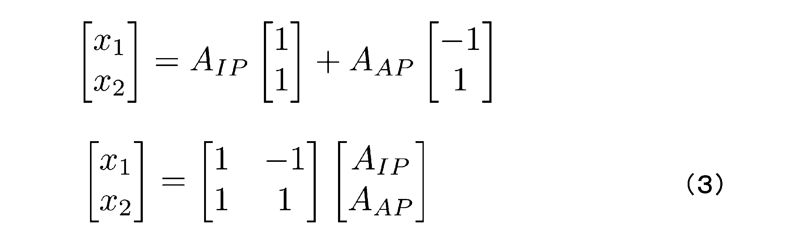
ここで、同相モードでの第1振動部22の変位をx1,IPおよび第2振動部23の変位をx2,IP、逆相モードでの第1振動部22の変位をx1,APおよび第2振動部23の変位をx2,APとし、同相側モード分離器31bで分離された同相モード成分の振幅をAIP,IP、逆相モード成分の振幅をAIP,APとし、逆相側モード分離器31aで分離された同相モード成分の振幅をAAP,IP、逆相モード成分の振幅をAAP,APとし、さらに、rIP=x2,IP/x1,IP、rAP=x2,AP/x1,APすると、(3)式から、以下の(4)~(7)式の関係が成り立つ。
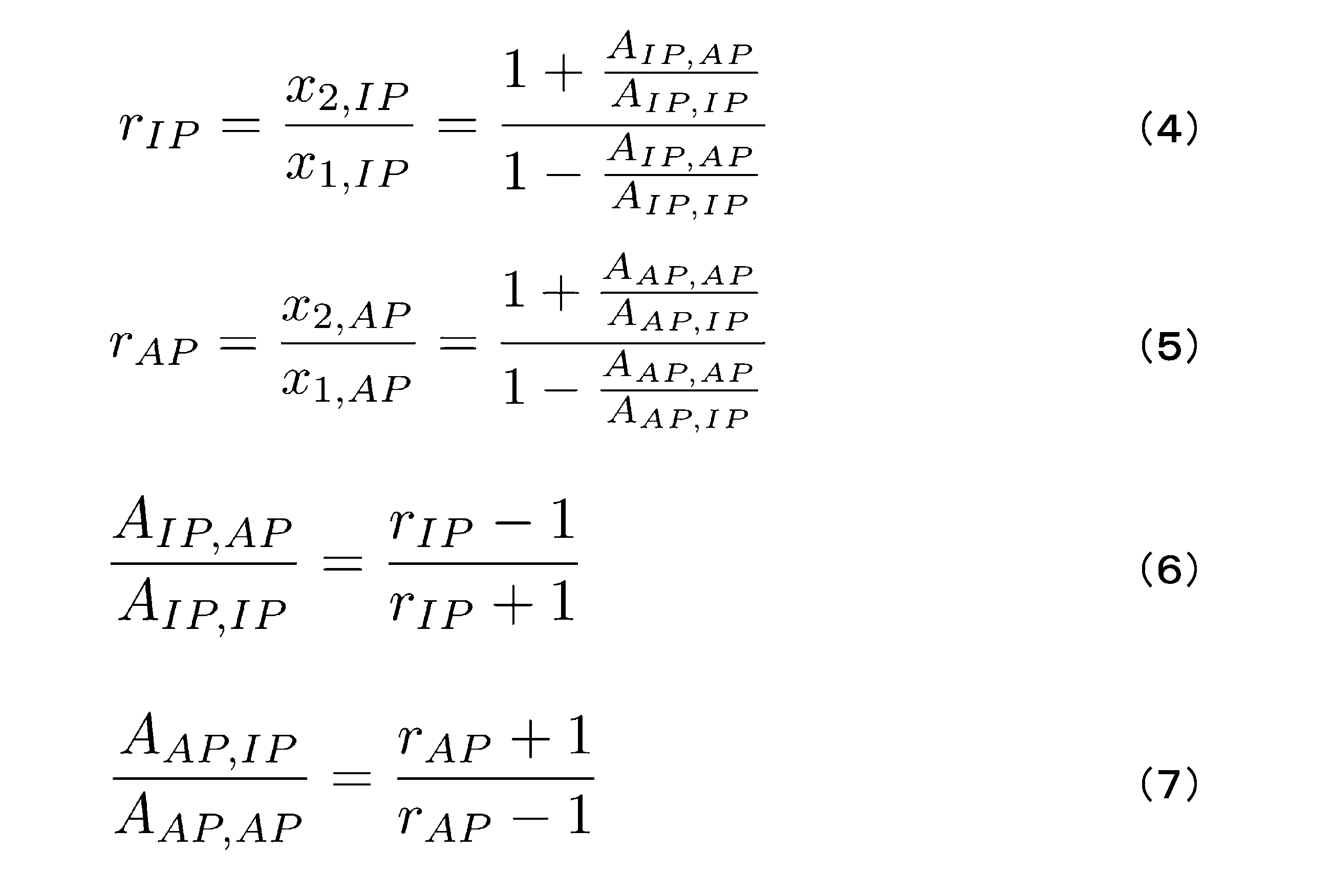
ここで、連結部26として第3のばね定数kcが小さいもの(弱いばね)を用いるため、(6)、(7)式は、それぞれ以下の(8)、(9)式のように近似できる。
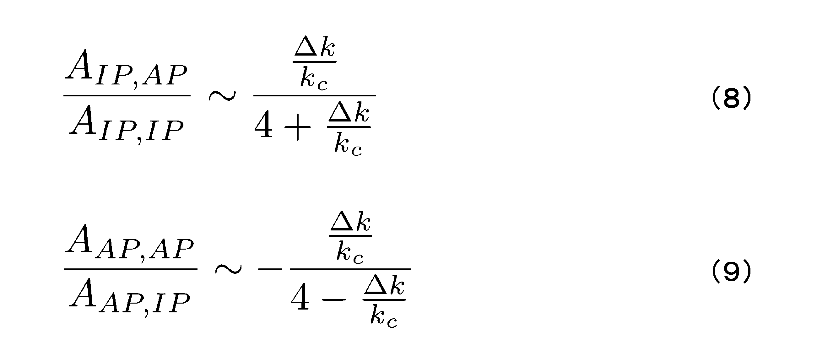
この(4)~(7)式を用いることにより、各モード形状rIP、rAPが求まり、さらに(1)式、(2)式等から、第1のばね定数k1と第2のばね定数k2との差Δkを求めることができる。また、同様に、(8)、(9)式を用いても、Δkを求めることができる。
<モードの干渉>
Δkが0でない場合には、MEMS振動子11の剛性の非対称性により、固有モードの形状が1および-1からずれる。この非対称な同相および逆相の振動モード形状を、±1のモード形状で表現すると、同相モード駆動で逆相モード振動が生じる、もしくは、逆相モード駆動で同相モード振動が生じることになる。そのため、同相制御ループの同相検出信号には、同相モードで制御されている振動成分に加え、逆相制御ループで生じる同相モード信号((7)式参照)が影響する。しかしながら、同相モードと逆相モードには周波数差があるため、同相制御ループの同相モードから出力される逆相制御ループの同相モード信号は、両モードの周波数差Δfで変調されている。図7に、同相側モード分離器31bを例に示す。図7に示すように、同相側モード分離器31bでは、同相制御ループからのIP駆動信号に加え、逆相制御ループで生じる同相モード信号も導入されている。
以下に、このようなモード干渉を排除して、物理量の変化を求める手法を示す。
Δkが0でない場合には、MEMS振動子11の剛性の非対称性により、固有モードの形状が1および-1からずれる。この非対称な同相および逆相の振動モード形状を、±1のモード形状で表現すると、同相モード駆動で逆相モード振動が生じる、もしくは、逆相モード駆動で同相モード振動が生じることになる。そのため、同相制御ループの同相検出信号には、同相モードで制御されている振動成分に加え、逆相制御ループで生じる同相モード信号((7)式参照)が影響する。しかしながら、同相モードと逆相モードには周波数差があるため、同相制御ループの同相モードから出力される逆相制御ループの同相モード信号は、両モードの周波数差Δfで変調されている。図7に、同相側モード分離器31bを例に示す。図7に示すように、同相側モード分離器31bでは、同相制御ループからのIP駆動信号に加え、逆相制御ループで生じる同相モード信号も導入されている。
以下に、このようなモード干渉を排除して、物理量の変化を求める手法を示す。
<モードの干渉の影響を排除できる場合>
ばね定数kcが変化したときには、(1)式および(2)式にしたがって同相モードおよび逆相モードのモード形状が変化する。このとき、振幅比が1および-1の参照信号を用いた場合には、モード間干渉が生じる可能性がある。このモード間干渉は、参照信号の振幅を(1)式および(2)式にしたがって動的に変化させれば除去することが可能である。
ばね定数kcが変化したときには、(1)式および(2)式にしたがって同相モードおよび逆相モードのモード形状が変化する。このとき、振幅比が1および-1の参照信号を用いた場合には、モード間干渉が生じる可能性がある。このモード間干渉は、参照信号の振幅を(1)式および(2)式にしたがって動的に変化させれば除去することが可能である。
このモードの干渉がおきている、Δkが0でない場合には、直交するモード形状がΔk=0の時とずれていることにより干渉が生じているため、検出手段14で検出されたΔkの値に応じてフィードバック回路を用いて、同相参照信号、逆相参照信号の振幅を変化させればよい。これにより、干渉を排除でき、(1)式および(2)式から、所定の物理量の変化を求めることができる。
あるいは、Δkが0の場合であれば、モードの干渉はおきないため、同相モードから生じる逆相モード、もしくは、逆相モードから生じる同相モード成分が0になるように、Δkを動的に調製できればよい。
このような構成にするには、共振制御回路32での逆相、同相の参照信号の振幅を検出し、フィードバック回路を用いて、Δkが常に0になるようにするような機構を追加すればよい。これにより、モード分離器31で、同相、逆相それぞれのモードの分離ができ、それぞれの振幅を分離することができる。
<モードの干渉を利用>
上記のモードの干渉の影響を排除する手法は、フィードバック回路を用いるため、装置が大掛かりになるなどの問題が生じる。そこで、本発明者らは、そのようなフィードバック回路を用いず、モードの干渉を利用して、物理量の変化を求める手法を検討した。
上記のモードの干渉の影響を排除する手法は、フィードバック回路を用いるため、装置が大掛かりになるなどの問題が生じる。そこで、本発明者らは、そのようなフィードバック回路を用いず、モードの干渉を利用して、物理量の変化を求める手法を検討した。
図7に示すように、同相側モード分離器31bでは、同相制御ループからのIP駆動信号に加え、逆相制御ループで生じる同相モード信号も導入されている。このため、本発明のモード分離手段12を備えたモード局在センサ10では、同相制御ループの同相信号成分をΔfで同期検波することにより、逆相モードで生じる同相モード成分、つまり、(5)式および(7)式によって表されるモード形状rAPを求め、このrAPからΔkを求めることができる。
すなわち、Δk=0のときには、同相側モード分離器31bにより分離された同相モード成分の振幅は、本来、一定値A0(以下、「基本振幅」という場合もある)になる。これに対し、Δkが0でないときには、その同相モード成分に、逆相制御ループで生じた同相モード成分が入り込んで干渉するため、同相モード成分の振幅は、A0を中心として振動する。この振動の振幅の大きさA1(以下、「干渉振幅」という場合もある)は、干渉している逆相モード側の成分の振幅の大きさに対応しており、周期は同相モード成分および逆相モード成分の共振周波数の差によって決まる。
同様に逆相制御ループの逆相振幅も、Δkが0でない場合には、同相制御ループで生じる逆相成分により変調される。よって、同様にして、この信号を復調することでモード形状rIPおよびΔkを求めることができる。
このように、モード局在センサ10は、モード分離手段12により分離された同相モード成分および逆相モード成分を用いて、それぞれを共振駆動することができる。その結果、この双方の情報を利用して、第1のばね定数と第2のばね定数との差を検出することができるため、いずれか一方のみを利用する場合に比べて、感度を高めることができる。また、感度を高めるために結合剛性を小さくしても、各モードを分離できるため、両方の質量の振幅を同程度にでき、変位測定に伴うノイズ増加を抑えることができる。
なお、モード局在センサ10で、検出手段14は、モード分離手段12により分離された同相モード成分の共振周波数、および、逆相モード成分の共振周波数の変調も検出し、その周波数変調も利用して、第1のばね定数と第2のばね定数との差の変化を求めるよう構成されていてもよい。この場合、同相モード成分および逆相モード成分の振幅だけでなく、共振周波数の変調も用いるため、さらに感度を高めることができる。
[実施例:シミュレーションによるMEMS振動子11の動作およびモード分離]
図5に示すモード局在センサ10を使用して、シミュレーションを行った。シミュレーションには、オープンソースの数値計算ソフト「Scilab/Xcos」を用いた。また、第1振動部22および第2振動部23の質量は、等しいものとした。
図5に示すモード局在センサ10を使用して、シミュレーションを行った。シミュレーションには、オープンソースの数値計算ソフト「Scilab/Xcos」を用いた。また、第1振動部22および第2振動部23の質量は、等しいものとした。
まず、図5に示すモード局在センサ10を用いてシミュレーションを行い、実際のモード局在センサ10の動きを再現できているか確認した。k1=k2(Δk=0)、感度をk1/kc=128とし、駆動手段13により第1振動部22のみを駆動したときの、MEMS振動子11の動作のシミュレーションを行った。このときの周波数に対する第1振動部22(M1)および第2振動部23(M2)の振幅ならびに位相の変化を、それぞれ図8(a)および(b)に示す。図8(a)および(b)に示すように、同相モード成分と逆相モード成分とが明瞭に確認された。また、同相モード成分および逆相モード成分共に、第1振動部22および第2振動部23の振幅比が1になることも確認された。この結果は、実際のモード局在センサ10の動きと一致しており、シミュレーションが実際のモード局在センサ10の動きを再現できていることが確認された。
さらに、実際のモード局在センサ10の動きを再現できているか確認するため、Δkをk2の1%(Δk/k2=0.01)とし、他の条件は図8と同じとして、MEMS振動子11の動作のシミュレーションを行った。このときの周波数に対する第1振動部22および第2振動部23の振幅ならびに位相の変化を、それぞれ図9(a)および(b)に示す。図9(a)および(b)に示すように、同相モード成分と逆相モード成分とが明瞭に確認されたが、各成分の共振周波数が高周波側に若干ずれることが確認された。また、同相モード成分では、第1振動部22の方が第2振動部23よりも振幅が大きくなり、逆相モード成分では、第2振動部23の方が第1振動部22よりも振幅が大きくなることが確認された。これらのシミュレーションでは、結合剛性が比較的大きく、同相モード成分と逆相モード成分とが周波数領域において明確に分離している。この結果も、実際のモード局在センサ10の動きと一致しており、シミュレーションが実際のモード局在センサ10の動きを再現できていることが確認された。
次に、k1=k2(Δk=0)とし、感度をk1/kc=843.75に上げて、他の条件は図8の場合と同じとして、MEMS振動子11の動作のシミュレーションを行った。このときの周波数に対する第1振動部22および第2振動部23の振幅ならびに位相の変化を、それぞれ図10(a)および(b)に示す。図10(a)および(b)に示すように、同相モード成分と逆相モード成分とが確認できるが、各成分の共振周波数が近づくため、ピークが重なり互いに混在していることが確認された。このため、ここまで感度を高めた場合には、同相モード成分と逆相モード成分とが重なってしまい、従来の方法では分離不可能である。本シミュレーションでは、実際のモード局在センサ10の混在の動きも再現できていることが確認された。
次に、図10と同じMEMS振動子11の動作に対し、図5に示すモード局在センサ10を使用して、本発明のモード分離器31により各モード成分を分離できるかのシミュレーションを行った。このときの同相モード信号で駆動した場合の、モード分離器31から出力される同相モード成分(IP)および逆相モード成分(AP)の振幅ならびに位相の変化を、それぞれ図11(a)および(b)に、逆相モード信号で駆動した場合の、モード分離器31から出力される同相モード成分および逆相モード成分の振幅ならびに位相の変化を、それぞれ図11(c)および(d)に示す。
図11(a)乃至(d)に示すように、本発明のモード分離器31により、同相モード成分および逆相モード成分が分離できることが確認された。この結果から、モード局在センサ10を使用することにより、図10に示すような同相モード成分と逆相モード成分とが互いに混在している場合であっても、同相モード成分と逆相モード成分とを分離することができるといえる。また、この分離された同相モード成分の振幅AIPと逆相モード成分の振幅AAPとを用いて、(8)式および(9)式によりΔkを求めることができる。また、(1)式および(2)式を用いても、Δkを求めることができる。
[シミュレーション:干渉での同相モード成分および逆相モード成分の振幅の利用]
次に、Δkをk2の0.1%(Δk/k2=0.001)および0.2%(Δk/k2=0.002)とし、他の条件は図11と同じとして、図5に示すモード局在センサ10を使用してシミュレーションを行った。分離された同相モード成分の位相を用いて、位相同期ループにより同相モードの駆動を行った。同様に、分離された逆相モード成分の位相を用いて,位相同期ループにより逆相モードの駆動を行った。それぞれのΔkのときの、同相側モード分離器31bにより分離された同相モード成分の振幅の時間変化(図中のIn-Phase)、および、逆相側モード分離器31aにより分離された逆相モード成分の振幅の時間変化(図中のAnti-Phase)を、それぞれ図12(a)および(b)に示す。
次に、Δkをk2の0.1%(Δk/k2=0.001)および0.2%(Δk/k2=0.002)とし、他の条件は図11と同じとして、図5に示すモード局在センサ10を使用してシミュレーションを行った。分離された同相モード成分の位相を用いて、位相同期ループにより同相モードの駆動を行った。同様に、分離された逆相モード成分の位相を用いて,位相同期ループにより逆相モードの駆動を行った。それぞれのΔkのときの、同相側モード分離器31bにより分離された同相モード成分の振幅の時間変化(図中のIn-Phase)、および、逆相側モード分離器31aにより分離された逆相モード成分の振幅の時間変化(図中のAnti-Phase)を、それぞれ図12(a)および(b)に示す。
図12(a)および(b)に示すように、同相モード成分に、逆相制御ループで生じる同相モード成分が重畳するため、干渉が生じ、同相モード成分の振幅が振動していることが確認された。同様に、逆相モード成分に、同相制御ループで生じる逆相モード成分が重畳するため、干渉が生じ、逆相モード成分の振幅が振動していることも確認された。また、各成分は、所定の振幅A0(同相制御ループで生じる同相成分、または、逆相制御ループで生じる逆相成分)を中心として振動しており、その振動の振幅の大きさA1は、Δkの大きさに対応していることが確認された。また、その振動の周期が同相モード成分および逆相モード成分の共振周波数の差に対応していることも確認された。
図12(a)では、A0=0.50u、A1=0.077uであるため、その振幅比はA1/A0=0.15となる。これに対し、図12(a)のシミュレーションに基づいて、(6)式により振幅比AAP/AIPを求めると、AAP/AIP=0.17となり、A1/A0=0.15と非常に近い値が得られる。また、図12(b)では、A0=0.50u、A1=0.15uであるため、その振幅比はA1/A0=0.29となる。これに対し、図12(b)のシミュレーションに基づいて、(6)式により振幅比AAP/AIPを求めると、AAP/AIP=0.297となり、A1/A0=0.29と非常に近い値が得られる。このように、振幅比A1/A0の値は、(6)式による振幅比AAP/AIPの値と非常に近い値となるため、振幅比A1/A0を求めることにより、Δkを求めることもできるといえる。
次に、Δkをk2の0.01%(Δk/k2=0.0001)および0.05%(Δk/k2=0.0005)とし、他の条件は図11と同じとして、図5に示すモード局在センサ10を使用してシミュレーションを行った。それぞれのΔkのときの、同相側モード分離器31bにより分離された同相モード成分の振幅の時間変化(図中のIn-Phase)、および、逆相側モード分離器31aにより分離された逆相モード成分の振幅の時間変化(図中のAnti-Phase)を、それぞれ図13(a)および(b)に示す。
図13(a)および(b)に示すように、図12(a)および(b)と同様に、同相モード成分の振幅および逆相モード成分の振幅が振動していることが確認された。図13(a)では、A0=0.50u、A1=0.011uであるため、その振幅比はA1/A0=0.02となる。これに対し、図13(a)のシミュレーションに基づいて、(6)式により振幅比AAP/AIPを求めると、AAP/AIP=0.0207となり、A1/A0=0.02と非常に近い値が得られる。また、図13(b)では、A0=0.50u、A1=0.041uであるため、その振幅比はA1/A0=0.082となる。これに対し、図13(b)のシミュレーションに基づいて、(6)式により振幅比AAP/AIPを求めると、AAP/AIP=0.095となり、A1/A0=0.082と近い値が得られる。
以上から、干渉が生じる場合であっても、同相モード成分、又は逆相モード成分の基本振幅A0と干渉振幅A1とからΔkを求めることができる。
[シミュレーション:同相モード成分および逆相モード成分の共振周波数の変調]
次に、Δkをk2の-0.1%(Δk/k2=-0.001)および-0.2%(Δk/k2=-0.002)とし、他の条件は図11と同じとして、図5に示すモード局在センサ10を使用してシミュレーションを行った。それぞれのΔkのときの、同相側モード分離器31bにより分離された同相モード成分の共振周波数の時間変化(図中のIn-Phase)、および、逆相側モード分離器31aにより分離された逆相モード成分の共振周波数の時間変化(図中のAnti-Phase)を、それぞれ図14(a)および(b)に示す。
次に、Δkをk2の-0.1%(Δk/k2=-0.001)および-0.2%(Δk/k2=-0.002)とし、他の条件は図11と同じとして、図5に示すモード局在センサ10を使用してシミュレーションを行った。それぞれのΔkのときの、同相側モード分離器31bにより分離された同相モード成分の共振周波数の時間変化(図中のIn-Phase)、および、逆相側モード分離器31aにより分離された逆相モード成分の共振周波数の時間変化(図中のAnti-Phase)を、それぞれ図14(a)および(b)に示す。
図14(a)および(b)に示すように、同相モード成分および逆相モード成分の共振周波数が振動(変調)しており、その振動の振幅の大きさがΔkの大きさに対応していることが確認された。このため、この共振周波数の変調の振幅の大きさに基づいて、Δkを求めることもできるといえる。
本発明に係るモード検出センサは、本発明の要旨を変更しない範囲において、種々の変更が可能である。第1振動部22、第2振動部23、ばね等は、必ずしも物理的なものでなくてもよく、一般化座標(モード座標)で本発明に係るモード局在センサと同様な表現が可能な質量やばね等であっても良い。例えば、弱く結合した複数のカンチレバーや、2軸振動子のX/Y軸の同相・逆相振動でも同様に動作する。
10 モード局在センサ
11 MEMS振動子
20 外部フレーム
21a、21b 支持部
22 第1振動部
23 第2振動部
24 第1接続部
25 第2接続部
26 連結部
12 モード分離手段
31 モード分離器
31a 逆相側モード分離器
31b 同相側モード分離器
32 共振制御回路
41a,41b 数値制御発信器(NCO)
42a,42b 比例積分制御器(PI)
13 駆動手段
43a,43b 比例積分制御器(PI)
14 検出手段
11 MEMS振動子
20 外部フレーム
21a、21b 支持部
22 第1振動部
23 第2振動部
24 第1接続部
25 第2接続部
26 連結部
12 モード分離手段
31 モード分離器
31a 逆相側モード分離器
31b 同相側モード分離器
32 共振制御回路
41a,41b 数値制御発信器(NCO)
42a,42b 比例積分制御器(PI)
13 駆動手段
43a,43b 比例積分制御器(PI)
14 検出手段
Claims (9)
- 多自由度振動系と、
前記多自由度振動系の振動に基づいた検出信号の同相モード成分および逆相モード成分を、参照信号を用いてそれぞれ分離するモード分離手段と、
前記モード分離手段により分離された前記同相モード成分および前記逆相モード成分に基づいて、前記多自由度振動系の剛性の非対称性の変化を検出し、その変化に基づいて所定の物理量の変化を求めるよう構成された検出手段とを
有することを特徴とするモード局在センサ。 - 前記モード分離手段は、前記同相モード成分と前記逆相モード成分との直交性に基づいて、前記検出信号と前記参照信号との内積をとることにより、前記同相モード成分と前記逆相モード成分とを分離するよう構成されていることを特徴とする請求項1記載のモード局在センサ。
- 前記参照信号は、同相および逆相の少なくともいずれか一方の前記多自由度振動系の振動に基づいて合成された信号と、その信号から位相が90度ずれた信号とから成ることを特徴とする請求項2記載のモード局在センサ。
- 前記検出手段は、前記同相モード成分の2つの代表点の振幅の比、および、前記逆相モード成分の2つの代表点の振幅の比に基づいて、前記剛性の非対称性の変化を検出するよう構成されていることを特徴とする請求項1記載のモード局在センサ。
- 前記モード分離手段は、検出信号から前記同相モード成分を分離する同相側モード分離器と、検出信号から前記逆相モード成分を分離する逆相側モード分離器とを有し、
前記多自由度振動系は、前記同相側モード分離器により分離された前記同相モード成分から形成される同相駆動信号と、前記逆相側モード分離器により分離された前記逆相モード成分から形成される逆相駆動信号とに基づいて駆動されるよう構成されており、
前記検出手段は、前記同相側モード分離器により分離された前記同相モード成分のうち、前記同相駆動信号による前記多自由度振動系の振動の振幅と、前記逆相駆動信号による前記多自由度振動系の振動の振幅との比、または、前記逆相側モード分離器により分離された前記逆相モード成分のうち、前記逆相駆動信号による前記多自由度振動系の振動の振幅と、前記同相駆動信号による前記多自由度振動系の振動の振幅との比に基づいて、前記剛性の非対称性の変化を検出するよう構成されていることを特徴とする請求項1記載のモード局在センサ。 - 前記検出手段は、前記同相モード成分および前記逆相モード成分のいずれか一方の振幅変動の平均値である基本振幅と、その振幅変動の振幅である干渉振幅とに基づいて、前記剛性の非対称性の変化を検出するよう構成されていることを特徴とする請求項1記載のモード局在センサ。
- 前記検出手段は、さらに前記同相モード成分および前記逆相モード成分の共振周波数に基づいて、前記剛性の非対称性の変化を求めるよう構成されていることを特徴とする請求項1記載のモード局在センサ。
- 請求項1乃至7いずれか1項に記載のモード局在センサを用いた機器。
- 多自由度振動系の振動に基づいた検出信号の同相モード成分および逆相モード成分を、参照信号を用いてそれぞれ分離するモード分離工程と、
前記モード分離工程により分離された前記同相モード成分および前記逆相モード成分に基づいて、前記多自由度振動系の剛性の非対称性の変化を検出し、その変化に基づいて所定の物理量の変化を求める検出工程とを
有することを特徴とする物理量検出方法。
Priority Applications (2)
| Application Number | Priority Date | Filing Date | Title |
|---|---|---|---|
| PCT/JP2023/017934 WO2024236643A1 (ja) | 2023-05-12 | 2023-05-12 | モード局在センサ、モード局在センサを用いた機器、および物理量検出方法 |
| JP2025520227A JPWO2024236643A1 (ja) | 2023-05-12 | 2023-05-12 |
Applications Claiming Priority (1)
| Application Number | Priority Date | Filing Date | Title |
|---|---|---|---|
| PCT/JP2023/017934 WO2024236643A1 (ja) | 2023-05-12 | 2023-05-12 | モード局在センサ、モード局在センサを用いた機器、および物理量検出方法 |
Publications (1)
| Publication Number | Publication Date |
|---|---|
| WO2024236643A1 true WO2024236643A1 (ja) | 2024-11-21 |
Family
ID=93518828
Family Applications (1)
| Application Number | Title | Priority Date | Filing Date |
|---|---|---|---|
| PCT/JP2023/017934 Ceased WO2024236643A1 (ja) | 2023-05-12 | 2023-05-12 | モード局在センサ、モード局在センサを用いた機器、および物理量検出方法 |
Country Status (2)
| Country | Link |
|---|---|
| JP (1) | JPWO2024236643A1 (ja) |
| WO (1) | WO2024236643A1 (ja) |
Citations (6)
| Publication number | Priority date | Publication date | Assignee | Title |
|---|---|---|---|---|
| JP2010531446A (ja) * | 2007-06-29 | 2010-09-24 | ノースロップ グルマン リテフ ゲーエムベーハー | コリオリジャイロ |
| JP2016507731A (ja) * | 2012-12-20 | 2016-03-10 | トロニクス・マイクロシステムズ | マイクロメカニカルz軸ジャイロスコープ |
| WO2018016190A1 (ja) * | 2016-07-21 | 2018-01-25 | ソニー株式会社 | ジャイロセンサ、信号処理装置、電子機器およびジャイロセンサの制御方法 |
| US20180031603A1 (en) * | 2016-07-27 | 2018-02-01 | Lumedyne Technologies Incorporated | Systems and methods for detecting inertial parameters using a vibratory accelerometer with multiple degrees of freedom |
| JP2020106522A (ja) * | 2018-12-19 | 2020-07-09 | 株式会社村田製作所 | 振動に強い多軸ジャイロスコープ |
| JP2022006389A (ja) * | 2020-06-24 | 2022-01-13 | セイコーエプソン株式会社 | 慣性センサー、電子機器、及び移動体 |
-
2023
- 2023-05-12 WO PCT/JP2023/017934 patent/WO2024236643A1/ja not_active Ceased
- 2023-05-12 JP JP2025520227A patent/JPWO2024236643A1/ja active Pending
Patent Citations (6)
| Publication number | Priority date | Publication date | Assignee | Title |
|---|---|---|---|---|
| JP2010531446A (ja) * | 2007-06-29 | 2010-09-24 | ノースロップ グルマン リテフ ゲーエムベーハー | コリオリジャイロ |
| JP2016507731A (ja) * | 2012-12-20 | 2016-03-10 | トロニクス・マイクロシステムズ | マイクロメカニカルz軸ジャイロスコープ |
| WO2018016190A1 (ja) * | 2016-07-21 | 2018-01-25 | ソニー株式会社 | ジャイロセンサ、信号処理装置、電子機器およびジャイロセンサの制御方法 |
| US20180031603A1 (en) * | 2016-07-27 | 2018-02-01 | Lumedyne Technologies Incorporated | Systems and methods for detecting inertial parameters using a vibratory accelerometer with multiple degrees of freedom |
| JP2020106522A (ja) * | 2018-12-19 | 2020-07-09 | 株式会社村田製作所 | 振動に強い多軸ジャイロスコープ |
| JP2022006389A (ja) * | 2020-06-24 | 2022-01-13 | セイコーエプソン株式会社 | 慣性センサー、電子機器、及び移動体 |
Also Published As
| Publication number | Publication date |
|---|---|
| JPWO2024236643A1 (ja) | 2024-11-21 |
Similar Documents
| Publication | Publication Date | Title |
|---|---|---|
| JP6143430B2 (ja) | バイアス補正機能を備えた振動型ジャイロ | |
| JP5554930B2 (ja) | 自己較正を備えた容量性バルク弾性波ディスク・ジャイロスコープ | |
| KR101178692B1 (ko) | 코리올리 자이로스코프 | |
| CA2586707C (en) | Oscillating micro-mechanical sensor of angular velocity | |
| US9958270B2 (en) | Vibratory gyroscope | |
| US8176780B2 (en) | Angular velocity sensor | |
| US10823569B1 (en) | Multiple axis sensing device based on frequency modulation and method of operation | |
| JP2015194507A (ja) | 微細加工された慣性センサのオフセット検出および補償 | |
| JP2012519295A5 (ja) | ||
| EP1440321A2 (en) | Angular rate sensor having a sense element constrained to motion about a single axis and flexibly attached to a rotary drive mass | |
| JP6973521B2 (ja) | 二重入力を有するジャイロスコープ | |
| JP6278604B2 (ja) | バイアス補正機能を備えた振動型ジャイロ | |
| JP5773844B2 (ja) | 出力安定性に優れた振動型ジャイロ | |
| JP2018021850A (ja) | バイアス補正機能を有する振動型ジャイロ、及び振動型ジャイロの使用方法 | |
| JP2015203604A (ja) | 高性能化が図られた振動型ジャイロ | |
| JP6305223B2 (ja) | バイアス安定化が図られた振動型ジャイロ、及び振動型ジャイロの使用方法 | |
| CN106066175B (zh) | 用于感测角速率的微机电陀螺仪及感测角速率的方法 | |
| JP2001264071A (ja) | 振動子駆動装置 | |
| JP4112684B2 (ja) | 振動ジャイロ | |
| WO2024236643A1 (ja) | モード局在センサ、モード局在センサを用いた機器、および物理量検出方法 | |
| JP2012202799A (ja) | バイアス安定性に優れた振動型ジャイロ | |
| JPWO2017159429A1 (ja) | ジャイロ装置およびジャイロ装置の制御方法 | |
| CN114076593B (zh) | 改进的惯性传感器 | |
| JP2008014727A (ja) | 加速度角速度センサ | |
| US11834329B2 (en) | Sensor control method |
Legal Events
| Date | Code | Title | Description |
|---|---|---|---|
| 121 | Ep: the epo has been informed by wipo that ep was designated in this application |
Ref document number: 23937390 Country of ref document: EP Kind code of ref document: A1 |
|
| ENP | Entry into the national phase |
Ref document number: 2025520227 Country of ref document: JP Kind code of ref document: A |
|
| WWE | Wipo information: entry into national phase |
Ref document number: 2025520227 Country of ref document: JP |
|
| NENP | Non-entry into the national phase |
Ref country code: DE |