WO2024232148A1 - 鋼の連続鋳造用鋳型及び鋼の連続鋳造方法 - Google Patents
鋼の連続鋳造用鋳型及び鋼の連続鋳造方法 Download PDFInfo
- Publication number
- WO2024232148A1 WO2024232148A1 PCT/JP2024/007978 JP2024007978W WO2024232148A1 WO 2024232148 A1 WO2024232148 A1 WO 2024232148A1 JP 2024007978 W JP2024007978 W JP 2024007978W WO 2024232148 A1 WO2024232148 A1 WO 2024232148A1
- Authority
- WO
- WIPO (PCT)
- Prior art keywords
- mold
- continuous casting
- cooling water
- steel
- mold plate
- Prior art date
- Legal status (The legal status is an assumption and is not a legal conclusion. Google has not performed a legal analysis and makes no representation as to the accuracy of the status listed.)
- Ceased
Links
Images




Classifications
-
- B—PERFORMING OPERATIONS; TRANSPORTING
- B22—CASTING; POWDER METALLURGY
- B22D—CASTING OF METALS; CASTING OF OTHER SUBSTANCES BY THE SAME PROCESSES OR DEVICES
- B22D11/00—Continuous casting of metals, i.e. casting in indefinite lengths
- B22D11/04—Continuous casting of metals, i.e. casting in indefinite lengths into open-ended moulds
-
- B—PERFORMING OPERATIONS; TRANSPORTING
- B22—CASTING; POWDER METALLURGY
- B22D—CASTING OF METALS; CASTING OF OTHER SUBSTANCES BY THE SAME PROCESSES OR DEVICES
- B22D11/00—Continuous casting of metals, i.e. casting in indefinite lengths
- B22D11/04—Continuous casting of metals, i.e. casting in indefinite lengths into open-ended moulds
- B22D11/055—Cooling the moulds
-
- B—PERFORMING OPERATIONS; TRANSPORTING
- B22—CASTING; POWDER METALLURGY
- B22D—CASTING OF METALS; CASTING OF OTHER SUBSTANCES BY THE SAME PROCESSES OR DEVICES
- B22D11/00—Continuous casting of metals, i.e. casting in indefinite lengths
- B22D11/16—Controlling or regulating processes or operations
-
- B—PERFORMING OPERATIONS; TRANSPORTING
- B22—CASTING; POWDER METALLURGY
- B22D—CASTING OF METALS; CASTING OF OTHER SUBSTANCES BY THE SAME PROCESSES OR DEVICES
- B22D11/00—Continuous casting of metals, i.e. casting in indefinite lengths
- B22D11/16—Controlling or regulating processes or operations
- B22D11/22—Controlling or regulating processes or operations for cooling cast stock or mould
Definitions
- the present invention relates to a mold for continuous casting of steel and a method for continuous casting of steel that can stably achieve continuous casting even at high speeds of 2.5 m/min or more.
- Typical surface cracks include surface vertical cracks, surface transverse cracks, and surface key cracks.
- Surface transverse cracks and surface key cracks are known to occur when strain is applied in the embrittlement temperature range in the secondary cooling zone of continuous casting.
- methods of preventing surface transverse cracks and surface key cracks are used, such as designing secondary cooling specifications that avoid the embrittlement temperature range at the bending correction point and adding embrittlement suppression elements.
- Patent Document 1 discloses a continuous casting mold in which a heterogeneous material filled section is formed on the inner wall surface of the mold, where the heterogeneous material filled section is filled with a heterogeneous material with a thermal conductivity different from that of the copper alloy that constitutes the mold. According to Patent Document 1, by keeping the thermal resistance R between the mold surface at the position where the heterogeneous material filled section is formed and a cooling water channel provided on the back surface of the mold within a specified range, it is possible to reduce surface cracks in the cast piece and suppress a decrease in the mold life due to mold surface cracks.
- Patent Document 2 also discloses a continuous casting mold in which a heterogeneous substance filled section is formed in the mold plate, where the heterogeneous substance has a different thermal conductivity from the copper alloy that constitutes the mold plate.
- this continuous casting mold it is said that by forming a water flow disturbance section that disturbs the water flow in the cooling water channel on the back surface of the mold plate in the area where the heterogeneous substance filled section is formed, it is possible to reduce surface cracks in the cast piece and extend the mold life.
- the inventors conducted casting tests using a filled mold in which the molten steel side surface of the mold plate was filled with Ni as disclosed in Patent Documents 1 and 2, and confirmed that the filled mold was highly effective in reducing vertical surface cracks in medium carbon steel.
- the temperature of the mold plate surface steadily exceeded 300°C when the casting speed reached a high speed of 2.5 m/min or more.
- the mold plate surface temperature steadily exceeded 300°C abnormalities such as plating peeling and deformation of the mold plate occurred, making it impossible to continue using the mold, which was an issue.
- a mold for continuous casting of steel comprising: a mold plate made of a copper alloy, the surface of which forms the inner wall surface of the mold, and cooling water channels formed on the back surface thereof; and a backup plate attached to the mold plate so as to cover the cooling water channels, wherein a plurality of dissimilar substance-filled portions filled with a dissimilar substance having a thermal conductivity different from that of the mold plate are formed in recesses formed in an area including at least the meniscus on the surface of the mold plate, and the total cross-sectional area of the cooling water channels on the back surface of the mold plate in the range including the area in which the plurality of dissimilar substance-filled portions are formed is smaller than the total cross-sectional area of the cooling water channels below the range.
- [10] A method for continuously casting steel using the mold for continuous casting of steel according to any one of [1] to [6], wherein the direction of flow of cooling water is from an upper end of the mold plate to a lower end of the mold plate.
- [11] A method for continuous casting of steel using the mold for continuous casting of steel according to any one of [1] to [6], wherein the thickness of the cast piece is 150 mm or less.
- the total cross-sectional area of the cooling water passages in the range including the region where the dissimilar substance-filled portion is formed is made smaller than the total cross-sectional area of the cooling water passages below that range.
- the heat transfer coefficient between the water flow and the cooling water passage increases, increasing the amount of convective heat transfer, so that heat can be effectively removed from the mold plate in the region where the dissimilar substance-filled portion is formed, and cooling can be achieved.
- FIG. 1 is a perspective view showing an example of a mold for continuous casting of steel according to the present embodiment.
- FIG. 2 is a schematic diagram showing an example of the surface of a mold plate constituting the long side of the mold according to this embodiment.
- FIG. 3 is a diagram showing the structure of the mold plate 22 in the area C enclosed by a square in FIG.
- FIG. 4 is a sectional view in the casting direction and a front view of a conventional mold plate.
- 5 is a cross-sectional view taken along lines UU and VV in FIG.
- FIG. 6 is a sectional view in the casting direction and a front view of a mold plate of the mold according to this embodiment.
- 7 is a cross-sectional view taken along lines UU and VV in FIG.
- FIG. 1 is a perspective view showing an example of a mold for continuous casting of steel according to the present embodiment.
- FIG. 2 is a schematic diagram showing an example of the surface of a mold plate constituting the long side of the mold according to this embodiment
- FIG. 8 is a graph showing the relationship between the distance from the upper end of the mold and the surface temperature of the mold plate.
- FIG. 9 is a cross-sectional view in the casting direction and a front view of the mold plate.
- FIG. 10 is a schematic diagram showing an example of installation of a pump for supplying cooling water to a mold.
- FIG. 11 is a graph showing the relationship between the total pump water volume and the pump source pressure.
- FIG. 12 is a schematic diagram showing an example of installation of a pump for supplying cooling water to the mold.
- FIG. 13 is a schematic diagram showing the mold used in Example 36.
- FIG. 14 is a schematic diagram showing the mold used in Comparative Example 30.
- FIG 1 is a perspective view showing an example of a mold 10 for continuous casting of steel according to this embodiment.
- a mold 10 for continuous casting of steel (hereinafter, sometimes simply referred to as "mold 10") used for continuous casting of a cast piece has a pair of opposing mold long sides 12 and a pair of opposing mold short sides 14 sandwiched between the mold long sides 12.
- a tundish (not shown) for containing molten steel 16 is placed above the mold 10, and an immersion nozzle 18 is installed at the bottom of the tundish.
- a rectangular internal space is formed in the mold 10 by the pair of mold long sides 12 and the pair of mold short sides 14, and an immersion nozzle 18 is inserted into this internal space.
- the sides of the mold long sides 12 and the mold short sides 14 that come into contact with the molten steel 16 are made of a mold plate made of a copper alloy, and a backup plate is placed on the back of this mold plate.
- Cooling water channels are formed on the back surface of the copper alloy mold plate that constitutes the mold long side 12 and mold short side 14, which contacts the molten steel 16.
- the mold 10 is cooled by passing cooling water through the cooling water channels.
- molten steel 16 is injected into the internal space of the mold 10 through a submerged nozzle 18, and the molten steel 16 is cooled and solidified by the mold 10, forming a solidified shell on the contact surface with the mold 10.
- the cast piece which has this solidified shell as its outer shell and unsolidified molten steel 16 inside, is continuously drawn in the cast piece drawing direction A, which is vertically downward, to cast the steel cast piece.
- the surface temperature of the mold plate (the temperature of the side in contact with the molten steel) rises due to contact with the molten steel 16 and the high-temperature cast piece, and the temperature reaches its maximum near the position of the meniscus M (the surface of the molten steel in the mold) in the mold.
- the position of the meniscus M is indicated by a dashed line.
- the slab withdrawal direction A and the mold width direction B are perpendicular directions.
- the mold plate it is preferable to use a copper alloy with high thermal conductivity that has high deformation resistance against thermal stress and can enhance the cooling effect of cooling water.
- strand support rolls (not shown) are arranged below the mold 10, and water spray nozzles or air mist spray nozzles are arranged between adjacent strand support rolls.
- the strand is cooled by spraying cooling water from the water spray nozzles or air mist spray nozzles onto the strand surface while being supported by the strand support rolls and pulled out, and after solidification is complete up to the center of the strand, it is cut to a specified length. In this way, a strand of a specified length is produced, which is to be subjected to the next process of hot rolling.
- the total cross-sectional area of the cooling water channels that cool the mold plate in the region where the dissimilar substance filling section is provided is made smaller than the total cross-sectional area of the cooling water channels below it. This increases the linear velocity of the cooling water in the region where the dissimilar substance filling section is provided, increasing the heat transfer coefficient in that region and the amount of convective heat transfer, allowing heat to be effectively removed from the dissimilar substance filling section and mold plate. As a result, the dissimilar substance filling section and the surrounding mold plate are effectively cooled, suppressing thermal stress that occurs at the boundary between the mold plate and the dissimilar substance filling section, extending the life of the mold 10 and enabling faster casting speeds to be achieved.
- FIG. 2 is a schematic diagram showing an example of the surface of a mold plate 22 that constitutes the mold long side 12 of the mold 10 according to this embodiment.
- Each of the mold long side 12 and mold short side 14 that constitute the mold 10 has a mold plate 22 whose surface forms the mold inner wall surface and has a cooling water channel formed on the back side, and a backup plate that is attached to this mold plate 22 with bolts and nuts.
- recesses formed in an area including the meniscus M are filled with a dissimilar material having a thermal conductivity different from that of the mold plate 22, forming multiple mutually independent dissimilar material filled sections 20.
- Multiple dissimilar material filled sections 20 are formed in the slab withdrawal direction A and mold width direction B at least near the meniscus M including the meniscus M.
- the dissimilar material filled sections 20 may be formed by processing the dissimilar material into a shape that fits into the recess and fitting it into the recess, but they may also be formed by filling the recess with the dissimilar material by plating means, thermal spraying means, etc. Filling the recess with the dissimilar material by plating means, thermal spraying means, etc. can prevent the occurrence of voids between the recess and the dissimilar material.
- each of the multiple dissimilar material filling sections 20 is regularly arranged on the surface of the mold plate 22 so that the heat flux on the mold inner wall surface from the mold inner wall surface toward the cooling water channel increases and decreases periodically.
- the thermal resistance of the mold plate 22 in the slab withdrawal direction A and mold width direction B in the region including the vicinity of the meniscus M increases and decreases regularly and periodically.
- This causes the heat flux from the solidified shell to the mold plate 22 in the vicinity of the meniscus M, i.e., in the early stages of solidification, to increase and decrease regularly and periodically.
- the regular and periodic increase and decrease in heat flux reduces the stress and thermal stress generated by the transformation of ⁇ iron to ⁇ iron, and the deformation of the solidified shell caused by these stresses is reduced.
- the reduction in deformation of the solidified shell homogenizes the non-uniform heat flux distribution caused by the deformation of the solidified shell, and the generated stress is dispersed to reduce the individual amounts of distortion. As a result, the occurrence of vertical cracks on the solidified shell surface is suppressed.
- the recesses do not have to be circular recesses that have a perfect circular shape on the surface of the mold plate 22, but may be pseudo-circular recesses that have a pseudo-circular shape.
- a pseudo-circular shape is a shape that does not have corners, such as an ellipse, or a square or rectangle with circular or elliptical corners.
- the recesses may be shaped like a petal pattern.
- the intervals between adjacent dissimilar material filled sections 20 are the same.
- the thermal conductivity of the dissimilar material is preferably 80% or less or 125% or more relative to the thermal conductivity of the mold plate 22.
- the thermal conductivity of the dissimilar material changes with changes in the ambient temperature. Therefore, the thermal conductivity of the dissimilar material and the mold plate is based on room temperature (normal temperature) at the time of manufacturing the mold. If the thermal conductivity of the dissimilar material is about 20% different from the thermal conductivity of the mold plate 22 at room temperature, the regular and periodic increase and decrease in heat flux on the inner wall surface of the mold can reduce the stress and thermal stress caused by the transformation of ⁇ iron to ⁇ iron.
- the thermal conductivity of the dissimilar material does not necessarily have to be within the above range, and the intervals between the dissimilar material filled sections 20 do not necessarily have to be the same.
- Examples of dissimilar materials with a thermal conductivity of 80% or less compared to that of the mold plate 22 include Ni (thermal conductivity: approximately 90 W/(m ⁇ K)) and Ni alloys (thermal conductivity: approximately 40-90 W/(m ⁇ K)), which are easy to plate or spray. Copper alloys (thermal conductivity: approximately 100-385 W/(m ⁇ K)) can be used for the mold plate 22, and for example, high thermal conductivity copper alloys (thermal conductivity: approximately 318 W/(m ⁇ K)) and low thermal conductivity copper alloys for electromagnetic stirring (thermal conductivity: approximately 119-239 W/(m ⁇ K)) can be used. However, metals other than Ni alloys and copper alloys may be used for the dissimilar materials and mold plate 22.
- the mold plate 22 can be made of pure copper (thermal conductivity: approximately 398 W/(m x K)) or the copper alloy mentioned above.
- thermal conductivity of copper alloys is lower than that of pure copper.
- a foreign substance filling section 20 similar to that on the long mold side 12 may also be formed on the surface of the short mold side 14.
- stress is likely to concentrate on the solidified shell on the side of the long mold side 12, and surface cracks are likely to occur on the long side surface. Therefore, it is necessary to provide a foreign substance filling section 20 on the long mold side 12 of the mold 10 according to this embodiment, but it is not necessarily necessary to provide a foreign substance filling section 20 on the short mold side 14.
- the dissimilar material filling section 20 in a region from an upper position that is a distance Q away from the position of the meniscus M during steady casting to a lower position that is a distance R away from the meniscus M.
- Distance Q is an arbitrary value greater than zero.
- Distance R can be calculated using the following formula (4).
- R 2 ⁇ Vc ⁇ 1000/60...(4)
- R is the distance (mm)
- Vc is the slab withdrawal speed (m/min) in the steel continuous casting process.
- the distance R is related to the time it takes for the solidified shell to pass through the area where the foreign substance filling section 20 is formed after solidification begins. It is preferable for the solidified shell to remain in the area where the foreign substance filling section 20 is installed for at least 2 seconds after solidification begins. In order for the solidified shell to remain in the area where the foreign substance filling section 20 is installed for at least 2 seconds after solidification begins, it is sufficient to install the foreign substance filling section 20 at least the distance R, calculated by equation (4), below the meniscus M.
- the time that the slab stays in the area where the dissimilar material filling section 20 is installed after the start of solidification is ensured to be 2 seconds or more, the effect of the periodic change in the heat flux from the inner wall surface of the mold toward the cooling water channel by the dissimilar material filling section 20 can be fully obtained.
- the time that the solidified shell stays in the area where the dissimilar material filling section 20 is installed is 2 seconds or more, the effect of suppressing the cracking of the slab surface can be obtained even during high-speed casting or casting of medium carbon steel, in which surface cracking is likely to occur.
- the time that the solidified shell passes through the area where the dissimilar material filling section 20 is installed is 4 seconds or more.
- the time of passing through the dissimilar material filling section 20 is ensured to be 1 second or more, the effect of the periodic change in the heat flux corresponding to that time can be obtained.
- the upper end of the region where the dissimilar substance filling portion 20 is formed need only be above the meniscus M and is not particularly limited. Therefore, the distance Q may be any value greater than zero. However, the meniscus M moves up and down during casting. For this reason, it is preferable that the dissimilar substance filling portion 20 is formed up to 20 mm above the meniscus M so that the upper end of the dissimilar substance filling portion 20 region is always above the meniscus M. It is more preferable that the dissimilar substance filling portion 20 is formed up to 40 mm above the meniscus M.
- the position of the meniscus M is generally 60 to 150 mm below the upper end of the mold plate 22, and the region where the dissimilar substance filling portion 20 is formed can be determined accordingly.
- the total cross-sectional area of the cooling water channels in the range including the region where the disparate substance filling section 20 of the mold plate 22 is formed is made smaller than the total cross-sectional area of the cooling water channels below that range.
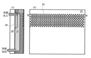
- Figure 3 is a diagram showing the structure of the mold plate 22 in area C enclosed by a rectangle in Figure 2.
- (a) is a plan view showing the front surface of the mold plate 22, and
- (b) is a plan view showing the back surface of the mold plate 22.
- (c) is a vertical cross-sectional view of the relevant area, and
- (d) is a horizontal cross-sectional view of the relevant area.
- a cooling water channel 26 is formed on the back surface of the mold plate 22.
- a backup plate 30 is attached to the back surface of the mold plate 22 so as to cover the cooling water channel 26.
- FIG. 4 is a cross-sectional view (a) in the casting direction and a front view (b) of a conventional mold plate 40.
- FIG. 5 is a U-U cross-sectional view (a) and a V-V cross-sectional view (b) of FIG. 4.
- FIG. 6 is a cross-sectional view (a) in the casting direction and a front view (b) of the mold plate 22 of the mold 10 according to this embodiment.
- FIG. 7 is a U-U cross-sectional view (a) and a V-V cross-sectional view (b) of FIG. 6.
- a spacer 28 is installed between the cooling water channel 26 in the area where the foreign material filling section 20 is formed and the backup plate 30.
- the spacer 28 may be installed in a range that includes the area where the foreign material filling section 20 is formed.
- the total cross-sectional area of the cooling water passages 26 is preferable to reduce the total cross-sectional area of the cooling water passages 26 and increase the linear flow velocity of the cooling water. This is to prevent the occurrence of steel leakage problems that may lead to breakout in the worst case, as the solidified shell cannot withstand the static pressure of the molten steel at the bottom end of the mold if the growth of the solidified shell in the mold is insufficient.
- a low thermal conductivity material is used for the dissimilar substance filling section 20
- the amount of heat removed from the mold is less than with the conventional mold plate 40, and there is a concern that the formation of the solidified shell may be insufficient.
- the solidified shell thickness can be calculated using the following formula (5).
- z_shell is the solidified shell thickness (mm).
- K is the solidification constant (20 to 27 mm/min 0.5 ).
- ts is the solidification time (min).
- z_m (m) is the distance from the meniscus M in the casting direction.
- Vc is the casting speed (m/min).
- Copper alloys are generally used for the mold plate 22, but when the temperature exceeds 350°C, the yield stress of the copper alloy drops significantly and the alloy softens, making it more susceptible to deformation.
- the outermost surface of the mold plate 22 facing the molten steel is generally plated with a Ni-Co or Ni-Cr plating layer 32, but the hardness of Ni alloys drops significantly when the temperature exceeds 350°C.
- a spacer 28 is installed to increase the linear flow rate of the cooling water in the area where the dissimilar substance filling section 20 is formed. This increases the heat transfer coefficient between the cooling water and the cooling water channel 26, increasing the amount of convective heat transfer, allowing heat to be effectively removed from the mold plate 22 in the area where the dissimilar substance filling section 20 is formed, and the mold plate 22 and the dissimilar substance filling section 20 can be effectively cooled. As a result, surface cracks in the cast piece can be suppressed, and peeling and cracks can be suppressed from occurring on the surface of the mold plate 22 and the plating layer 32.
- the linear flow velocity of the cooling water in the cooling water channel 26 is preferably 7.0 m/sec or more. In this linear flow velocity region, the Reynolds number Re of the water in the channel is about 40,000, resulting in turbulent flow (Re>2300). To increase the local heat removal near the meniscus M, the linear flow velocity of the cooling water should be set to 10.0 m/sec or more. In principle, by setting the linear flow velocity of the cooling water to 10.0 m/sec or more, it is possible to obtain the effect of lowering the surface temperature of the mold plate 22 by about 30°C.
- the solidified shell may rise near the meniscus M, and fine cracks that become the starting point of vertical cracks may occur. If the linear flow velocity of the cooling water remains fast even in the lower part, tensile stress in the width direction of the risen part of the solidified shell may continue to occur, and the opening of vertical cracks or the growth of deep depressions may progress. In contrast, if the cross-sectional area of the cooling water channel 26 is increased from about 200 mm below the meniscus M from the upper end of the mold, the linear flow velocity of the cooling water is slowed down, which has the advantage that the opening of vertical cracks and the growth of depression depth do not occur.
- the inventors have confirmed that in a general copper alloy mold in which the dissimilar material filling portion 20 is not embedded across the meniscus M, when the linear flow velocity is 12 m/sec or more, vertical cracks in the slab tend to become apparent. It has also been confirmed that when the cross-sectional area of the cooling water channel 26 near the meniscus M is made smaller than that below it for this mold, the occurrence of vertical cracks in the slab tends to be suppressed. Furthermore, it is preferable that the total channel area A1 of the cooling water channel 26 on the back surface of the mold plate in the range including the area in which the meniscus M and the dissimilar material filling portion 20 are formed and the total cross-sectional area A2 of the cooling water channel 26 below this range satisfy the relationship A1 ⁇ 0.8 ⁇ A2. As a result, it has been confirmed that the occurrence of severe vertical cracks in the slab with a depth of 2 mm or more is suppressed not only in the mold 10 according to this embodiment but also in the case of a conventional mold.
- the mold 10 according to this embodiment in which the dissimilar material filled section 20 is embedded across the meniscus M, does not cause vertical cracks in the cast piece even when high-speed casting of 2.5 m/min or more is performed.
- the mold 10 it is preferable to form the foreign material filling section 20 and the cooling water channel 26 in the mold plate 22 so as to satisfy at least one of the conditions in the following formulas (1) to (3).
- d is the width (mm) of the foreign substance filling portion 20 in the mold width direction B.
- P is the mold width between adjacent foreign substance filling portions 20.
- ... is the width (mm) of the dissimilar material filled portion 20 in the direction A.
- L is the interval (mm) between adjacent dissimilar material filled portions 20 in the slab drawing direction A.
- Vc is the continuous casting f is the vibration frequency (1/min) of the mold 10 in the continuous casting process of steel.
- A1 is the area where the meniscus M and the foreign material filled portion 20 are formed. It is the total cross-sectional area (mm 2 ) of the cooling water passages 26 on the back surface of the mold plate 22 including the area where the cooling water passages 26 are installed. A2 is the total cross-sectional area (mm 2 ) of the cooling water passages 26 below the above range.
- the "spacing distance” is the distance between two adjacent portions of each portion in the direction A of drawing out the slab or the width direction of the mold plate 22. This refers to the center distance at B (see Figure 3).
- the boundary between the total cross-sectional area A1 and the total cross-sectional area A2 is divided into a position that includes the foreign substance filling section 20 and a position that does not include the foreign substance filling section 20.
- the range of the total cross-sectional area A1 includes the area where the foreign substance filling section 20 is formed, and may also include some areas where the foreign substance filling section 20 is not formed. However, it is preferable that the range of the total cross-sectional area A1 is the area where the foreign substance filling section 20 is formed.
- the total cross-sectional area A1 and the total cross-sectional area A2 are both the sum of the cross-sectional areas of the respective slits.
- the linear flow velocity of the cooling water in the cooling water passage 26 can be calculated by dividing the water volume by the total cross-sectional area.
- a dissimilar substance filling section 20 is provided on the copper plate surface near the meniscus, so the cooling of the area where the dissimilar substance filling section 20 is provided is about 10% weaker than the area where the dissimilar substance filling section 20 is not provided. Therefore, in the mold 10 according to this embodiment, the total cross-sectional area A1 is made 20% smaller than the total cross-sectional area A2. This increases the linear velocity of the cooling water in the area where the dissimilar substance filling section 20 is provided by about 20%, and enhances the heat transfer from the slits, so that the cooling of the area where the dissimilar substance filling section 20 is provided can be maintained at the same level as in the conventional case where the dissimilar substance filling section 20 is not provided.
- the mold plate 22 is cooled by the cooling water flowing through the cooling water channel 26 on the back surface of the mold plate 22, so heat is removed from the mold plate 22 radially through the cooling water channel 26. Therefore, uneven cooling occurs on the surface of the mold plate 22 between areas close to and far from the cooling water channel 26.
- the spacing distance P of the foreign material filling section 20 in the mold width direction B is less than the spacing distance S of the cooling water channel 26, and it is preferable that the width d of the foreign material filling section 20 is less than the spacing distance P.
- the width d of the foreign substance filling section 20 is preferably 2 mm or more and 20 mm or less. If the foreign substance filling section 20 is pseudo-circular, the width d may be the circle equivalent diameter calculated from the following formula (6).
- width d or equivalent circle diameter 2 mm or more By making the width d or equivalent circle diameter 2 mm or more, it becomes easy to fill the circular or pseudo-circular recesses with dissimilar substances by plating or thermal spraying.
- width d and equivalent circle diameter 20 mm or less solidification delays due to reduced heat flux in the dissimilar substance filling portion 20 are suppressed, stress concentration on the solidified shell at that position is prevented, and it becomes easier to suppress the occurrence of surface cracks in the solidified shell.
- the mold 10 When pouring molten steel 16 into the mold 10, in order to prevent the molten steel 16 from sticking to the mold 10, the mold 10 is vibrated while mold powder is poured onto the surface of the molten steel 16. It is known that this vibration causes periodic oscillation marks to form on the surface of the slab in the direction A of withdrawal, and the thickness of the slab tends to change periodically in the direction A of withdrawal.
- Transverse cracks in the slab can be suppressed by making the width of the dissimilar material filled sections 20, the distance between adjacent dissimilar material filled sections 20, the slab withdrawal speed, and the vibration frequency f of the mold satisfy the above formula (2).
- transverse cracks in the slab can be suppressed by making the width of the dissimilar material filled sections 20 in the slab withdrawal direction A smaller than the length (pitch) of one period in the slab withdrawal direction A of the thickness increase or decrease in the slab caused by the oscillation mark.
- the mold 10 oscillates, a concave depression is formed in the slab per oscillation period. This depression is the oscillation mark.
- the oscillation marks are generated at a pitch of 1000 x Vc/f.
- the oscillation of the mold 10 generates the oscillation marks at a pitch of 1000 x Vc/f, it is extremely important to prevent concentrated strain and stress from being applied to this location in order to prevent transverse cracks. Therefore, in the mold 10 according to this embodiment, it is preferable to provide a heterogeneous material filling portion at a pitch of 1000 x Vc/f or less. This makes it possible to avoid artificial thermal stress acting on the oscillation mark valleys, which in turn prevents the generation of fine cracks in the oscillation mark valleys during the initial solidification stage, and prevents the cracks from expanding and propagating in the secondary cooling zone.
- the foreign substance filling section 20 is formed in the mold plate 22 so as to satisfy the condition of the following formula (7).
- t is the filling thickness (mm) of the foreign substance in the foreign substance filling section 20
- d is the width (mm) of the foreign substance filling section 20 in the width direction B of the mold.
- the filling thickness of the foreign material filling section 20 is less than 0.5 mm, the fluctuation of the heat flux in the foreign material filling section 20 may be insufficient.
- the filling thickness is equal to or less than the width d (mm) of the foreign material filling section in the mold width direction.
- the filling thickness t is preferably equal to or less than 10 mm. If the filling thickness is thicker than 10 mm, it becomes difficult to fill the recesses with the foreign material.
- the thermal conductivity of the foreign material is lower than that of the mold plate 22 and the filling thickness is thicker than 10 mm, the amount of heat removed from the mold plate 22 will be reduced. This will cause the surface temperature of the mold plate 22 to rise, and if the surface temperature exceeds 350° C., this will lead to abnormalities in the copper plate and plating, so it is preferable that the filling thickness is equal to or less than 10 mm.
- the plating layer 32 can be formed by plating or spraying commonly used nickel or alloys containing nickel, such as nickel-cobalt alloys (Ni-Co alloys) and nickel-chromium alloys (Ni-Cr alloys).
- the cooling strength (heat transfer coefficient) of the mold 10 is determined by the linear flow velocity of the cooling water flowing through the cooling water passage 26, it is preferable to increase the linear flow velocity of the cooling water to 7.0 m/sec or more during high-speed casting.
- the average linear flow velocity of the cooling water is calculated using the following formula (8), so in order to increase the linear flow velocity of the cooling water to 7.0 m/sec or more, it is important to properly design the amount of cooling water and the cooling water passage 26.
- the amount of heat removed from the mold 10 can be estimated from the temperature difference of the cooling water entering and leaving the mold and the temperature of a thermocouple embedded in the copper plate of the mold.
- the amount of heat removed from the mold 10 has a maximum value in the range of 20 mm to 80 mm below the meniscus M in the casting direction, and thereafter tends to decrease gradually.
- Figure 8 is a graph showing the relationship between the distance from the upper end of the mold and the surface temperature of the mold plate 40.
- the mold copper plate surface temperature reaches its maximum at the temperature maximum point directly below the meniscus M as shown in Figure 8, where the surface temperature of the mold plate 40 is at its highest. If the surface temperature of this mold plate 40 becomes higher than 350°C, the yield stress of the copper plate and the hardening point of the surface plating will be reached, raising concerns about the occurrence of mold plating peeling. As shown in Figure 8, this curve shifts to the higher temperature side as the casting speed increases. Therefore, if the surface temperature of the mold plate is likely to exceed 350°C, it is necessary to increase the amount of cooling water or reduce the total cross-sectional area of the cooling water passages 26 to increase the linear flow rate of the cooling water.
- the temperature rise at the filled area will be even greater.
- the surface temperature of the mold plate will vary depending on the filling depth of the low thermal conductivity material, the material of the mold plate, and the thickness of the mold plate, so attention must be paid to the surface temperature of the mold plate during high-speed casting.
- the surface temperature of the mold plate 40 reaches a maximum value near the meniscus M, and below that the temperature distribution is relatively low and gentle. For this reason, the areas where the copper plate or plating is susceptible to peeling or damage tend to be concentrated within about 200 mm below the meniscus M, and it is preferable to increase the amount of heat dissipation in this area and keep the surface temperature of the mold plate below 350°C.
- the total cross-sectional area of the cooling water channels 26 on the back surface of the mold plate in the range including the area where the meniscus M and the foreign material filled portion 20 are formed is made smaller than the total cross-sectional area of the cooling water channels 26 below that range. This enhances the heat removal from the mold plate 22, and the surface temperature of the mold plate 22 can be kept below 350°C even when continuous casting is performed at a casting speed of 2.5 m/min or more.
- thermocouple it is preferable to embed a thermocouple within the mold plate 22 within a range of 20 to 100 mm below the meniscus M and use the temperature measured by the thermocouple.
- the surface temperature of the mold plate 22 can be calculated using the temperature measured by the thermocouple, and the amount of cooling water required and the total cross-sectional area of the cooling water channel 26 can be calculated so that the surface temperature of the mold plate 22 is 350°C or less. From this result, the upper limit of the possible casting speed can also be determined.
- Figure 9 shows a cross-sectional view (a) and a front view (b) of the mold plate 22 in the casting direction.
- the flow direction of the cooling water will be explained using Figure 9.
- the flow direction of the cooling water is from the upper end of the mold close to the meniscus M to the lower end of the mold. This allows low-temperature cooling water to be supplied to the cooling water channel 26 near the meniscus M, thereby increasing the cooling capacity of the mold 10 near the meniscus M.
- the heterogeneous material filling section 20 is embedded near the meniscus M, which is expected to provide a uniform cooling effect. Therefore, in the continuous steel casting method of this embodiment, it is preferable to pass the cooling water from the upper end of the mold close to the meniscus M toward the lower end of the mold. This increases the cooling capacity of the upper end of the mold, where the surface temperature is likely to be high, and makes it easier to keep the surface temperature of the mold plate 22 below 350°C.
- cooling water is generally supplied from a common pump to the cooling water passages 26 of the mold long sides 12 and the mold short sides 14.
- cooling water is generally supplied from a common pump to the cooling water passages 26 of the mold long sides 12 and the mold short sides 14.
- this configuration even if one attempts to improve the precision of the cooling water supply, due to the flow rate-pressure relationship determined by the piping diameter, when one attempts to increase the amount of cooling water on either the mold long sides 12 or the mold short sides 14, there are cases in which the amount of cooling water cannot be increased because pressure is not generated on the remaining surface.
- FIG. 10 is a schematic diagram showing an example of the installation of pumps that supply cooling water to the mold 10.
- a total of four pumps two at the front and rear of the long side 12 of the mold and two on the left and right of the short side 14 of the mold, can be installed independently, but this would not only be extremely costly, but would also make the control complicated. Since this would mean having multiple backup pumps in case of breakdown, this is not desirable as operating equipment for continuous steel casting, which operates without interruption almost 365 days a year.
- the main pump it is preferable to have a system in place that allows cooling water to flow continuously through all four sides of the mold, including the long side 12 and the short side 14 of the mold, even in small amounts, even in the event of a pump failure. Therefore, it is preferable for the main pump to be shared by both the long side 12 and the short side 14 of the mold.
- Figure 11 is a graph showing the relationship between the total pump water volume and the pump source pressure.
- the dashed line is a system diagram of the pump.
- a mold used in continuous casting of steel is composed of a pair of mold long sides 12 and a pair of mold short sides 14, and the pipe diameter of the mold short sides 14, where the amount of water is less, is generally smaller than the pipe diameter of the mold long sides 12, where the amount of water is greater. Therefore, even if an amount of water corresponding to the required linear flow velocity is supplied to the mold 10 for the long and short sides, the effect of pressure loss on the short sides is so great that the target flow rate may not be achieved, even if the long sides can be supplied.
- FIG 12 is a schematic diagram showing an example of the installation of a pump that supplies cooling water to the mold.
- a common pump P that handles the overall water supply and a boost pump BP to further increase the amount of water on the short side in series piping.
- a boost pump BP separate from the common pump P as a pump to increase this water pressure, the pump can compensate for the pressure in the piping on the short side 14 of the mold.
- the pump control method is preferably a mechanism in which the boost pump BP operates when a specific casting speed is reached.
- the amount of cooling water at the short side 14 of the mold can be adjusted to a target amount by increasing the water pressure with the boost pump BP in conjunction with an increase in the amount of cooling water at the long side 12 of the mold.
- One effective method for controlling the amount of cooling water is to change the amount of cooling water in response to the casting speed, but because the change in the mold cooling capacity is not as steep as that of the secondary cooling water, it is easier to control it by setting the water volume at several stepped points in relation to the casting speed.
- the control method involves determining the water volume setting of the mold pump, and adjusting the pump setting and the total cross-sectional area of the cooling water passages 26 so that the surface temperature of the mold plate obtained from the thermocouple temperature of the mold plate 22 is 350°C or less.
- the spacer 28 installed on the backup plate to increase the linear flow rate at the location corresponding to the position of the foreign material filling section may be made movable using a servo motor, pneumatic cylinder, hydraulic cylinder, etc. This allows the total cross-sectional area A1 of the cooling water passages 26 above the mold, including the meniscus M and the foreign material filling section 20, to be changed without dismantling the mold 10.
- a slowly cooled mold powder is used to suppress the occurrence of vertical cracks in the cast slab.
- the growth of the solidified shell is likely to become non-uniform due to the transformation stress accompanying the ⁇ transformation, and when stress concentration occurs in the circumferential direction, defects such as vertical cracks and depressions occur at that location.
- a crystallization powder is used for medium carbon steel, which actively generates a crystalline phase in the mold powder and achieves uniform slow cooling in the mold.
- Low-basicity mold powders are mainly vitreous, and can be used to cool the mold more strongly.
- high-basicity mold powders are effective in preventing vertical cracks, but their mold cooling capacity is reduced. For this reason, it is difficult to achieve both high-speed casting and prevention of vertical cracks with high-basicity mold powders.
- high-basicity mold powders are expensive, and from the viewpoint of production costs, it is preferable to use mold powders with a basicity of CaO/SiO 2 of less than 1.2 instead.
- the mold plate 22 is provided with a dissimilar material filled section 20, and the solidified shell is subjected to a regular temperature change to suppress an increase in local heat flux to a specific location, thereby suppressing the generation of longitudinal cracks and depressions in the slab.
- a mold powder having a basicity CaO/ SiO2 of less than 1.2 By using this mold powder, the mold can be cooled strongly, which can accommodate an increase in the casting speed and also suppresses longitudinal cracks in the slab.
- the continuous casting method for steel according to this embodiment is preferably applied to continuous casting of thin slabs with a casting speed of 3.0 m/min to 8.0 m/min and a thickness of 150 mm or less.
- the cast slab is basically directly connected to the rolling process while being heated in a tunnel furnace, and no refinement process such as slab cleaning can be performed. For this reason, if there are slab defects such as vertical cracks, the coil quality deteriorates and the yield rate drops. Therefore, continuous casting of thin slabs with high speed casting has not been actively implemented in the production of hypoperitectic medium carbon steel, which is a type of steel that is difficult to cast, and special steel with a high alloy content.
- the production of hypoperitectic medium carbon steel can be performed by continuous casting of thin slabs, and productivity is improved remarkably.
- the thickness of the mold becomes very thin, so in order to avoid the outer diameter of the submerged nozzle that supplies molten steel not being able to fit inside the mold, a mold having a special funnel shape (funnel shape) at the center of the long side width is used.
- a heterogeneous material filling portion 20 in a range of 50 mm across the boundary of the funnel shape within a range of 0 to 200 mm below the meniscus M. This suppresses uneven cooling even at the boundary of the funnel shape, and the occurrence of vertical cracks and breakouts in the thin slab can be suppressed.
- Example 1 Next, examples in which the mold according to the present embodiment was evaluated by operating an actual continuous casting machine will be described.
- Example 1 the following three types of molds were used for evaluation.
- Comparative Example 1 A typical continuous casting mold in which a portion filled with a different material is not formed on the inner wall surface of the mold and the cross-sectional area of the cooling water passage is constant in the casting direction.
- Comparative Example 2 A continuous casting mold in which a portion filled with a different material is formed on the inner wall surface of the mold, but the cross-sectional area of the cooling water passage is constant in the casting direction.
- Invention Example 1 A continuous casting mold in which a dissimilar substance-filled portion is formed on the mold inner wall surface.
- All of the above molds had a rectangular inner space with a long side of 2.1 m and a short side of 0.22 m, and the mold plates that made up the long and short sides were made from a copper alloy with a thermal conductivity of approximately 380 (W/(m x K)) at room temperature.
- the target steel types for continuous casting were all steel types that are normally cast, from very low carbon steel to medium carbon steel.
- the chemical components were C; 0.0008-0.25 mass%, Si; 0.002-1.2 mass%, Mn; 0.10-2.0 mass%, P; 0.005-0.030 mass%, S; 0.001-0.02 mass%, Al; 0.001-0.06 mass%, with the balance being Fe and unavoidable impurities.
- the mass of molten steel per charge was 300 tons. While pouring molten steel into the prepared mold, the mold was cooled while vibrating in the direction of the slab withdrawal to form a solidified shell, and the solidified shell was withdrawn to cast the slab.
- the slab withdrawal speed Vc was 0.3-2.6 (m/min).
- Example 1 mold powder was poured onto the molten steel in the vibrating mold to prevent the molten steel from sticking to the mold.
- the mold powder used had a basicity ((mass % CaO)/(mass % SiO 2 )) of 0.6 to 1.8. Of these, mold powder with a high basicity of 1.5 to 1.8 was used for medium carbon steel.
- Example 1 the goal was to perform continuous casting of 3,000 charges without changing the mold, and surface cracks on the long side of the mold were checked after every 100 charges had been cast.
- the surface of the long side of the mold was visually checked for peeling or cracks in the plating or copper plate, and if any abnormalities were found, the continuous casting operation was stopped at that point.
- Surface cracks on the slab were checked after every continuous casting.
- Surface cracks on the slab were checked by visually inspecting the surface of the slab after casting of medium carbon steel, which is highly sensitive to cracks, and performing a penetrant test (color check), and vertical cracks were confirmed along the direction of the slab being drawn out.
- Comparative Example 1 Comparative Example 2, and Example 1, the cooling water was supplied to the mold at a rate set so that the linear flow velocity in the cooling water channel was 7.0 m/sec.
- a spacer 28 was installed to increase the linear flow velocity in the cooling water channel to 10.0 m/sec.
- Comparative Example 1 At the end of casting of 2600 charges, a crack occurred in the plating layer of the mold plating plate, and casting was stopped. The incidence rate of longitudinal cracks in the medium carbon steel slab was 8.0%. Comparative Example 2: At the end of casting of 2000 charges, peeling and cracks occurred in the plating layer of the mold plating plate, and casting was discontinued. The incidence rate of longitudinal cracks in the medium carbon steel slab was 0.5%. Invention Example 1: At the end of casting 3,000 charges, there was no peeling or cracking in the plating layer of the mold plating plate. The longitudinal crack occurrence rate of the medium carbon steel slab was 0.2%. Thus, in Example 1, no surface cracks occurred on the mold plates constituting the long sides of the mold even at the end of casting 3,000 charges, and the effect of reducing vertical cracks in the medium carbon steel slab was also confirmed.
- Example 1 the casting speed was further increased to 3.0 m/min, and casting was continued until 3,500 charges were reached. As a result, even when casting was performed at the maximum casting speed of 3.0 m/min, which increases the thermal load, no surface cracks occurred on the mold plate that constitutes the long side of the mold, and no tendency for vertical cracks to increase in the medium carbon steel slab was observed.
- Example 1 it was possible to perform the target number of continuous castings of 3,000 charges without replacing the mold, and it was confirmed that the service life of the mold could be improved compared to Comparative Examples 1 and 2. Furthermore, even when operated at a casting speed of 2.5 m/min or more, there was no damage to the mold surface. This result is believed to be due to the fact that the mold could be cooled more efficiently by reducing the total cross-sectional area of the cooling water channel in the region where the dissimilar material filling section 20 is formed and increasing the linear flow velocity.
- Example 2 Next, Example 2 will be described (Invention Examples 2 to 35, Comparative Examples 3 to 29) in which continuous steel casting was performed in the same manner as in Example 1.
- Example 2 in order to change the foreign substance filling portion, cooling water passage, and casting conditions, the foreign substance filling portion and the like were provided in the narrow side mold, which allows the conditions to be easily changed by inserting and removing the mold for each test, and continuous steel casting was performed by changing the conditions of the narrow side mold.
- Example 2 the number of casting charges in one invention example and comparative example was set to 5. Furthermore, the target steel type for continuous casting was limited to medium carbon steel with chemical components of 0.08-0.17 mass% C, 0.10-0.30 mass% Si, 0.50-1.20 mass% Mn, 0.010-0.030 mass% P, 0.005-0.015 mass% S, 0.020-0.040 mass% Al, with the balance being Fe and unavoidable impurities, because the occurrence of vertical cracks on the surface of the cast slab is likely to be a problem.
- the target steel type for continuous casting was limited to medium carbon steel with chemical components of 0.08-0.17 mass% C, 0.10-0.30 mass% Si, 0.50-1.20 mass% Mn, 0.010-0.030 mass% P, 0.005-0.015 mass% S, 0.020-0.040 mass% Al, with the balance being Fe and unavoidable impurities, because the occurrence of vertical cracks on the surface of the cast slab is likely to be a problem.
- the width d (mm) of the foreign substance filled portion 20 in the mold width direction, the spacing distance P (mm) of the foreign substance filled portion 20 in the mold width direction, the width e (mm) of the foreign substance filled portion 20 in the slab withdrawal direction A, the total upper cross-sectional area A1 of the cooling water passage, the total lower cross-sectional area A2 of the cooling water passage, etc., shown in FIG. 3 were changed. Furthermore, in each of the invention examples 2 to 35 and the comparative examples 3 to 29, continuous casting was performed by changing the vibration frequency (1/min), the slab withdrawal speed Vc (m/min), and the mold powder basicity.
- thermocouple was embedded in the area from the meniscus M to 50 mm below in the casting direction, and the temperature was measured with the thermocouple. The temperature was measured at one-second intervals, and the temperature data was recorded. The distance from the thermocouple temperature measurement point to the molten steel side surface of the mold plate 22 was 15 mm. Based on a heat transfer model, the surface temperature of the mold plate 22 was calculated from the temperature of the thermocouple.
- Comparative Examples 3 to 29 are general continuous casting molds that do not have a foreign material filled section, and molds that have a foreign material filled section but the cross-sectional area of the cooling slit channel corresponding to that section is the same as below it.
- this maximum copper plate surface temperature is 350°C or less, it can be said that the mold plate is cooled stably. It has been confirmed that if the maximum copper plate surface temperature is 350°C or less, there is no peeling of the plating or the occurrence of cracks on the copper plate surface.
- Example 2 surface cracks were also checked for the slabs after every continuous casting run. Ten slabs can be produced in a continuous casting run of one charge. Five charges are continuously cast in each of the invention examples and comparative examples, so 50 slabs are cast in each of the invention examples and comparative examples. Penetrant testing was performed on all of these slabs, and the surfaces of the slabs that had been subjected to the penetrant testing were visually inspected to confirm surface cracks. Since the detailed specifications of the mold were changed only on the short sides this time, the data evaluated in Example 2 was limited to surface cracks at the short sides only.
- Example 2 to 35 the formula (3) above was satisfied, and the copper plate surface temperature was 350°C or less at the meniscus position. This suppressed the occurrence of cracks and abnormalities on the copper plate surface, and no cracks or abnormalities occurred on the copper plate surface even under high-speed casting conditions of a casting speed of 2.5 m/min or more.
- Example 3 In order to confirm the effect of the mold according to this embodiment in high speed casting, a thin slab continuous caster was used to perform continuous casting of steel in Example 3.
- a mold having a funnel-shaped curved surface 42 in the center in the width direction of the mold copper plate was used to continuously cast a slab of a certain size, with the slab width being 1250 mm and the slab thickness at the mold bottom end being 75 mm (Invention Example 36 and Comparative Example 30).
- the target steel type for continuous casting was medium carbon steel with the following chemical components: C; 0.08-0.17% by mass, Si; 0.10-0.30% by mass, Mn; 0.50-1.20% by mass, P; 0.010-0.030% by mass, S; 0.005-0.015% by mass, Al; 0.020-0.040% by mass, with the balance being Fe and unavoidable impurities.
- the casting speed was 4.0-5.0 m/min
- the mold vibration stroke was 6 mm.
- Figure 13 is a schematic diagram showing the mold used in Example 36.
- Figure 14 is a schematic diagram showing the mold used in Comparative Example 30.
- a mold was used in which a dissimilar material filling section 44 with nickel alloy of 5 mm diameter x 1.5 mm depth was embedded in the meniscus M and in the boundary portion of the funnel-shaped curved surface 42 within a range of 0 to 200 mm below the meniscus M.
- a spacer 28 was installed on the backup plate side so that the total cross-sectional area of the cooling water channel within a range of 0 to 200 mm below the meniscus from the upper end was 0.75 times the total cross-sectional area below that to the lower end.
- Comparative Example 30 a mold was used in which the dissimilar material filling section 44 was not embedded and no spacer 28 was installed.
- Example 36 Casting tests of five charges each were conducted for Example 36 and Comparative Example 30.
- the slabs after casting are generally heated continuously in a tunnel furnace and then rolled, but in this test, the thin slabs were turned into cold pieces to check the condition of surface cracks after casting.
- Example 36 continuous casting was performed for all five charges at a casting speed of 4.0 m/min or more and 5.0 m/min or less. No longitudinal cracks were observed on the surface of the cast slab, confirming that the quality was satisfactory even when continuous rolling was performed. In contrast, in Comparative Example 30, a breakout occurred in one of the five charges, and complete casting was not achieved. After casting, longitudinal cracks occurred in 66% of the slabs. Most of the longitudinal cracks occurred at positions corresponding to the boundaries of the funnel shape.
- Example 36 the copper plate surface temperature estimated from the copper plate thermocouple temperature near the meniscus during casting was stable at around 320°C even at a casting speed of 5.0 m/min, and no abnormalities were observed on the copper plate surface after casting.
- Comparative Example 30 the copper plate surface temperature estimated from the copper plate thermocouple temperature near the meniscus M during casting tended to exceed 350°C from a casting speed of around 4.0 m/min, so further increases in the casting speed were abandoned.
- Example 36 shows that the use of the mold of Example 36 is extremely effective for thin slab continuous casting, which requires high-speed casting of 2.5 m/min or more.
- the canal method in which a round hole is machined in the casting direction and water is passed through it for cooling, is also widely used for mold cooling in thin slab continuous casters. With the canal method, the same effect can be obtained by changing the upper and lower hole diameters, so either cooling method can be used.
Landscapes
- Engineering & Computer Science (AREA)
- Mechanical Engineering (AREA)
- Continuous Casting (AREA)
Priority Applications (3)
| Application Number | Priority Date | Filing Date | Title |
|---|---|---|---|
| KR1020257036516A KR20250168594A (ko) | 2023-05-10 | 2024-03-04 | 강의 연속 주조용 주형 및 강의 연속 주조 방법 |
| JP2024535401A JP7777744B2 (ja) | 2023-05-10 | 2024-03-04 | 鋼の連続鋳造用鋳型及び鋼の連続鋳造方法 |
| CN202480029545.7A CN121079162A (zh) | 2023-05-10 | 2024-03-04 | 钢的连续铸造用铸模及钢的连续铸造方法 |
Applications Claiming Priority (2)
| Application Number | Priority Date | Filing Date | Title |
|---|---|---|---|
| JP2023-077840 | 2023-05-10 | ||
| JP2023077840 | 2023-05-10 |
Publications (1)
| Publication Number | Publication Date |
|---|---|
| WO2024232148A1 true WO2024232148A1 (ja) | 2024-11-14 |
Family
ID=93429982
Family Applications (1)
| Application Number | Title | Priority Date | Filing Date |
|---|---|---|---|
| PCT/JP2024/007978 Ceased WO2024232148A1 (ja) | 2023-05-10 | 2024-03-04 | 鋼の連続鋳造用鋳型及び鋼の連続鋳造方法 |
Country Status (4)
| Country | Link |
|---|---|
| JP (1) | JP7777744B2 (https=) |
| KR (1) | KR20250168594A (https=) |
| CN (1) | CN121079162A (https=) |
| WO (1) | WO2024232148A1 (https=) |
Citations (7)
| Publication number | Priority date | Publication date | Assignee | Title |
|---|---|---|---|---|
| JPH01135151U (https=) * | 1988-03-10 | 1989-09-14 | ||
| JPH0342144A (ja) * | 1989-07-06 | 1991-02-22 | Kawasaki Steel Corp | 連続鋳造用鋳型の冷却方法およびその鋳型 |
| JPH09512484A (ja) * | 1994-04-01 | 1997-12-16 | アクタス インダストリーズ,インコーポレイティド | 金属連続鋳造用鋳型 |
| JP2001179413A (ja) * | 1999-12-17 | 2001-07-03 | Sumitomo Metal Ind Ltd | 鋼の連続鋳造方法 |
| WO2013069121A1 (ja) * | 2011-11-09 | 2013-05-16 | 新日鐵住金株式会社 | 鋼の連続鋳造装置 |
| WO2020095932A1 (ja) * | 2018-11-09 | 2020-05-14 | Jfeスチール株式会社 | 鋼の連続鋳造用鋳型及び鋼の連続鋳造方法 |
| CN218744746U (zh) * | 2022-07-14 | 2023-03-28 | 江苏兴荣铜业有限公司 | 一种下引法铸造高电率铜锭的冷却装置 |
Family Cites Families (1)
| Publication number | Priority date | Publication date | Assignee | Title |
|---|---|---|---|---|
| JP6439762B2 (ja) | 2015-08-18 | 2018-12-19 | Jfeスチール株式会社 | 鋼の連続鋳造方法 |
-
2024
- 2024-03-04 JP JP2024535401A patent/JP7777744B2/ja active Active
- 2024-03-04 KR KR1020257036516A patent/KR20250168594A/ko active Pending
- 2024-03-04 CN CN202480029545.7A patent/CN121079162A/zh active Pending
- 2024-03-04 WO PCT/JP2024/007978 patent/WO2024232148A1/ja not_active Ceased
Patent Citations (7)
| Publication number | Priority date | Publication date | Assignee | Title |
|---|---|---|---|---|
| JPH01135151U (https=) * | 1988-03-10 | 1989-09-14 | ||
| JPH0342144A (ja) * | 1989-07-06 | 1991-02-22 | Kawasaki Steel Corp | 連続鋳造用鋳型の冷却方法およびその鋳型 |
| JPH09512484A (ja) * | 1994-04-01 | 1997-12-16 | アクタス インダストリーズ,インコーポレイティド | 金属連続鋳造用鋳型 |
| JP2001179413A (ja) * | 1999-12-17 | 2001-07-03 | Sumitomo Metal Ind Ltd | 鋼の連続鋳造方法 |
| WO2013069121A1 (ja) * | 2011-11-09 | 2013-05-16 | 新日鐵住金株式会社 | 鋼の連続鋳造装置 |
| WO2020095932A1 (ja) * | 2018-11-09 | 2020-05-14 | Jfeスチール株式会社 | 鋼の連続鋳造用鋳型及び鋼の連続鋳造方法 |
| CN218744746U (zh) * | 2022-07-14 | 2023-03-28 | 江苏兴荣铜业有限公司 | 一种下引法铸造高电率铜锭的冷却装置 |
Also Published As
| Publication number | Publication date |
|---|---|
| JPWO2024232148A1 (https=) | 2024-11-14 |
| JP7777744B2 (ja) | 2025-12-01 |
| KR20250168594A (ko) | 2025-12-02 |
| CN121079162A (zh) | 2025-12-05 |
Similar Documents
| Publication | Publication Date | Title |
|---|---|---|
| JP5692451B2 (ja) | 連続鋳造用鋳型及び鋼の連続鋳造方法 | |
| KR101941506B1 (ko) | 연속 주조용 주형 및 강의 연속 주조 방법 | |
| JP6439762B2 (ja) | 鋼の連続鋳造方法 | |
| JP6428721B2 (ja) | 連続鋳造用鋳型及び鋼の連続鋳造方法 | |
| JP6947737B2 (ja) | 鋼の連続鋳造方法 | |
| JP7004085B2 (ja) | 鋼の連続鋳造用鋳型及び鋼の連続鋳造方法 | |
| JP6365604B2 (ja) | 鋼の連続鋳造方法 | |
| JP6003850B2 (ja) | 連続鋳造用鋳型の製造方法及び鋼の連続鋳造方法 | |
| JP6003851B2 (ja) | 連続鋳造用鋳型及び鋼の連続鋳造方法 | |
| JP6947192B2 (ja) | 鋼の連続鋳造用鋳型及び鋼の連続鋳造方法 | |
| JP6740924B2 (ja) | 連続鋳造用鋳型及び鋼の連続鋳造方法 | |
| JP6787359B2 (ja) | 鋼の連続鋳造方法 | |
| JP5962733B2 (ja) | 鋼の連続鋳造方法 | |
| JP7777744B2 (ja) | 鋼の連続鋳造用鋳型及び鋼の連続鋳造方法 | |
| KR20190017978A (ko) | 연속 주조용 주형 및 강의 연속 주조 방법 | |
| JP2024047887A (ja) | 連続鋳造用鋳型、連続鋳造用鋳型の製造方法及び鋼の連続鋳造方法 | |
| JP7020376B2 (ja) | 鋼の連続鋳造用鋳型及び鋼の連続鋳造方法 |
Legal Events
| Date | Code | Title | Description |
|---|---|---|---|
| WWE | Wipo information: entry into national phase |
Ref document number: 2024535401 Country of ref document: JP |
|
| 121 | Ep: the epo has been informed by wipo that ep was designated in this application |
Ref document number: 24803263 Country of ref document: EP Kind code of ref document: A1 |
|
| ENP | Entry into the national phase |
Ref document number: 1020257036516 Country of ref document: KR Free format text: ST27 STATUS EVENT CODE: A-0-1-A10-A15-NAP-PA0105 (AS PROVIDED BY THE NATIONAL OFFICE) |
|
| WWE | Wipo information: entry into national phase |
Ref document number: KR1020257036516 Country of ref document: KR |
|
| NENP | Non-entry into the national phase |
Ref country code: DE |