WO2024232144A1 - 電極および電池 - Google Patents
電極および電池 Download PDFInfo
- Publication number
- WO2024232144A1 WO2024232144A1 PCT/JP2024/006946 JP2024006946W WO2024232144A1 WO 2024232144 A1 WO2024232144 A1 WO 2024232144A1 JP 2024006946 W JP2024006946 W JP 2024006946W WO 2024232144 A1 WO2024232144 A1 WO 2024232144A1
- Authority
- WO
- WIPO (PCT)
- Prior art keywords
- electrode
- solid electrolyte
- active material
- battery
- positive electrode
- Prior art date
- Legal status (The legal status is an assumption and is not a legal conclusion. Google has not performed a legal analysis and makes no representation as to the accuracy of the status listed.)
- Ceased
Links
Images

Classifications
-
- H—ELECTRICITY
- H01—ELECTRIC ELEMENTS
- H01M—PROCESSES OR MEANS, e.g. BATTERIES, FOR THE DIRECT CONVERSION OF CHEMICAL ENERGY INTO ELECTRICAL ENERGY
- H01M4/00—Electrodes
- H01M4/02—Electrodes composed of, or comprising, active material
- H01M4/13—Electrodes for accumulators with non-aqueous electrolyte, e.g. for lithium-accumulators; Processes of manufacture thereof
- H01M4/131—Electrodes based on mixed oxides or hydroxides, or on mixtures of oxides or hydroxides, e.g. LiCoOx
-
- H—ELECTRICITY
- H01—ELECTRIC ELEMENTS
- H01M—PROCESSES OR MEANS, e.g. BATTERIES, FOR THE DIRECT CONVERSION OF CHEMICAL ENERGY INTO ELECTRICAL ENERGY
- H01M10/00—Secondary cells; Manufacture thereof
- H01M10/05—Accumulators with non-aqueous electrolyte
- H01M10/052—Li-accumulators
- H01M10/0525—Rocking-chair batteries, i.e. batteries with lithium insertion or intercalation in both electrodes; Lithium-ion batteries
-
- H—ELECTRICITY
- H01—ELECTRIC ELEMENTS
- H01M—PROCESSES OR MEANS, e.g. BATTERIES, FOR THE DIRECT CONVERSION OF CHEMICAL ENERGY INTO ELECTRICAL ENERGY
- H01M10/00—Secondary cells; Manufacture thereof
- H01M10/05—Accumulators with non-aqueous electrolyte
- H01M10/056—Accumulators with non-aqueous electrolyte characterised by the materials used as electrolytes, e.g. mixed inorganic/organic electrolytes
- H01M10/0561—Accumulators with non-aqueous electrolyte characterised by the materials used as electrolytes, e.g. mixed inorganic/organic electrolytes the electrolyte being constituted of inorganic materials only
- H01M10/0562—Solid materials
-
- H—ELECTRICITY
- H01—ELECTRIC ELEMENTS
- H01M—PROCESSES OR MEANS, e.g. BATTERIES, FOR THE DIRECT CONVERSION OF CHEMICAL ENERGY INTO ELECTRICAL ENERGY
- H01M4/00—Electrodes
- H01M4/02—Electrodes composed of, or comprising, active material
- H01M4/13—Electrodes for accumulators with non-aqueous electrolyte, e.g. for lithium-accumulators; Processes of manufacture thereof
-
- H—ELECTRICITY
- H01—ELECTRIC ELEMENTS
- H01M—PROCESSES OR MEANS, e.g. BATTERIES, FOR THE DIRECT CONVERSION OF CHEMICAL ENERGY INTO ELECTRICAL ENERGY
- H01M4/00—Electrodes
- H01M4/02—Electrodes composed of, or comprising, active material
- H01M4/36—Selection of substances as active materials, active masses, active liquids
- H01M4/48—Selection of substances as active materials, active masses, active liquids of inorganic oxides or hydroxides
- H01M4/52—Selection of substances as active materials, active masses, active liquids of inorganic oxides or hydroxides of nickel, cobalt or iron
- H01M4/525—Selection of substances as active materials, active masses, active liquids of inorganic oxides or hydroxides of nickel, cobalt or iron of mixed oxides or hydroxides containing iron, cobalt or nickel for inserting or intercalating light metals, e.g. LiNiO2, LiCoO2 or LiCoOxFy
-
- H—ELECTRICITY
- H01—ELECTRIC ELEMENTS
- H01M—PROCESSES OR MEANS, e.g. BATTERIES, FOR THE DIRECT CONVERSION OF CHEMICAL ENERGY INTO ELECTRICAL ENERGY
- H01M4/00—Electrodes
- H01M4/02—Electrodes composed of, or comprising, active material
- H01M4/62—Selection of inactive substances as ingredients for active masses, e.g. binders, fillers
-
- H—ELECTRICITY
- H01—ELECTRIC ELEMENTS
- H01M—PROCESSES OR MEANS, e.g. BATTERIES, FOR THE DIRECT CONVERSION OF CHEMICAL ENERGY INTO ELECTRICAL ENERGY
- H01M4/00—Electrodes
- H01M4/02—Electrodes composed of, or comprising, active material
- H01M4/62—Selection of inactive substances as ingredients for active masses, e.g. binders, fillers
- H01M4/624—Electric conductive fillers
- H01M4/625—Carbon or graphite
-
- H—ELECTRICITY
- H01—ELECTRIC ELEMENTS
- H01M—PROCESSES OR MEANS, e.g. BATTERIES, FOR THE DIRECT CONVERSION OF CHEMICAL ENERGY INTO ELECTRICAL ENERGY
- H01M4/00—Electrodes
- H01M4/02—Electrodes composed of, or comprising, active material
- H01M4/62—Selection of inactive substances as ingredients for active masses, e.g. binders, fillers
- H01M4/628—Inhibitors, e.g. gassing inhibitors, corrosion inhibitors
-
- H—ELECTRICITY
- H01—ELECTRIC ELEMENTS
- H01M—PROCESSES OR MEANS, e.g. BATTERIES, FOR THE DIRECT CONVERSION OF CHEMICAL ENERGY INTO ELECTRICAL ENERGY
- H01M4/00—Electrodes
- H01M4/02—Electrodes composed of, or comprising, active material
- H01M2004/026—Electrodes composed of, or comprising, active material characterised by the polarity
- H01M2004/028—Positive electrodes
-
- H—ELECTRICITY
- H01—ELECTRIC ELEMENTS
- H01M—PROCESSES OR MEANS, e.g. BATTERIES, FOR THE DIRECT CONVERSION OF CHEMICAL ENERGY INTO ELECTRICAL ENERGY
- H01M2300/00—Electrolytes
- H01M2300/0017—Non-aqueous electrolytes
- H01M2300/0065—Solid electrolytes
-
- H—ELECTRICITY
- H01—ELECTRIC ELEMENTS
- H01M—PROCESSES OR MEANS, e.g. BATTERIES, FOR THE DIRECT CONVERSION OF CHEMICAL ENERGY INTO ELECTRICAL ENERGY
- H01M2300/00—Electrolytes
- H01M2300/0017—Non-aqueous electrolytes
- H01M2300/0065—Solid electrolytes
- H01M2300/0068—Solid electrolytes inorganic
-
- Y—GENERAL TAGGING OF NEW TECHNOLOGICAL DEVELOPMENTS; GENERAL TAGGING OF CROSS-SECTIONAL TECHNOLOGIES SPANNING OVER SEVERAL SECTIONS OF THE IPC; TECHNICAL SUBJECTS COVERED BY FORMER USPC CROSS-REFERENCE ART COLLECTIONS [XRACs] AND DIGESTS
- Y02—TECHNOLOGIES OR APPLICATIONS FOR MITIGATION OR ADAPTATION AGAINST CLIMATE CHANGE
- Y02E—REDUCTION OF GREENHOUSE GAS [GHG] EMISSIONS, RELATED TO ENERGY GENERATION, TRANSMISSION OR DISTRIBUTION
- Y02E60/00—Enabling technologies; Technologies with a potential or indirect contribution to GHG emissions mitigation
- Y02E60/10—Energy storage using batteries
Definitions
- This disclosure relates to electrodes and batteries.
- Patent Document 1 discloses a negative electrode having a current collector and an active material layer in contact with at least one surface of the current collector.
- the active material layer has aggregates in which parts of multiple active materials or parts of multiple conductive assistants are aggregated.
- the electrode of the present disclosure comprises: An active material; A solid electrolyte; A conductive assistant; An electrode comprising: The length of the interface of the conductive assistant per unit area of the cross section of the electrode is greater than 0.58 ⁇ m/ ⁇ m 2 .
- This disclosure makes it possible to improve the discharge capacity retention rate of a battery.
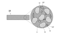
- FIG. 1 is a cross-sectional view showing a schematic configuration of an electrode according to the first embodiment.
- FIG. 2 is a cross-sectional view showing a schematic configuration of a battery in accordance with the second embodiment.
- a conductive additive is added to an electrode material containing an active material and a solid electrolyte in order to improve electronic conductivity.
- the aggregated conductive additive sinks in the direction of gravity, which may result in an uneven distribution of the conductive additive inside the electrode.
- the conductive additive is distributed unevenly, it is difficult to form a good electronic conduction path. As a result, the discharge capacity retention rate of the battery decreases.
- the inventors conducted extensive research to improve the discharge capacity retention rate of batteries. As a result, they came up with the electrode disclosed herein.
- FIG. 1 is a cross-sectional view showing a schematic configuration of an electrode 100 according to the first embodiment.
- the electrode 100 includes an active material 10, a solid electrolyte 11, and a conductive additive 12.
- the interface of the conductive assistant 12 formed by contact between the solid electrolyte 11 or the active material 10 and the conductive assistant 12 is defined as the interface 12f.
- the observation area when observing the cross section of the electrode 100 is defined as A (unit: ⁇ m 2 ).
- the total length of the interfaces 12f confirmed within the observation area is defined as L (unit: ⁇ m).
- the value obtained as L/A is defined as the interface perimeter Z.
- the interface perimeter Z represents the length of the interface 12f of the conductive assistant 12 per unit area of the cross section of the electrode 100.
- the interface perimeter Z is greater than 0.58 ⁇ m/ ⁇ m 2 , a good electron conduction path can be formed. As a result, the discharge capacity retention rate of the battery can be improved.
- the conductive additive often forms aggregates inside the electrode. If the size of the aggregates is too large, or if the amount of aggregates is too large, the distribution of the conductive additive inside the electrode may become uneven. If the distribution of the conductive additive becomes uneven, it is difficult to form a good electronic conduction path. As a result, the discharge capacity retention rate of the battery decreases.
- the inventors have found that in the cross section of an electrode, the length of the interface of the conductive assistant per unit area of the cross section of the electrode, i.e., the interface perimeter Z, can reflect the dispersion state of the conductive assistant.
- the larger the interface perimeter Z the more uniformly the conductive assistant is dispersed, and the easier it is for the active material present in the electrode to exchange electrons.
- the interface perimeter Z is greater than 0.58 ⁇ m/ ⁇ m 2 , a good electron conduction path can be formed. As a result, the discharge capacity retention rate of the battery can be improved.
- the following method is used to calculate the interface perimeter Z.
- the electrode 100 is processed with a cross-section polisher to form a smooth cross section.
- the direction of cross section processing may be in any direction of the electrode 100.
- a cross section parallel to the in-plane direction of the plate-like electrode 100 may be formed, a cross section parallel to the thickness direction of the plate-like electrode 100 may be formed, or a cross section non-parallel to both the in-plane direction and the thickness direction may be formed.
- the formed cross section is observed by a scanning electron microscope (SEM) to obtain a cross-sectional image (magnification: 500 times). Since it is desirable to evaluate the average shape of the electrode 100, it is desirable to observe a region sufficiently wide with respect to the median diameter of the particle group of the active material 10 contained in the electrode 100 by the SEM. For example, when the median diameter of the particles of the active material 10 contained in the electrode 100 is D (unit: ⁇ m), it is desirable that the area A of the measurement region satisfies A ⁇ (20D) 2 .
- a measurement region where the area A of the measurement region satisfies A ⁇ (20D) 2 is selected from the obtained cross-sectional image, and analyzed by image processing software Image J.
- Image J image processing software
- the conductive assistant 12 is determined as a particle in the cross-sectional image of the electrode 100.
- the length of the interface 12f between the conductive assistant 12 and the solid electrolyte 11 or the active material 10 is calculated.
- the total length L of the interface 12f of the particles of the conductive assistant 12 is calculated.
- the total length L of the interfaces 12f is divided by the observation area A to calculate the length of the interfaces 12f of the conductive assistant 12 per unit area of the cross section of the electrode 100, i.e., the interface perimeter Z.
- the perimeter of this aggregate means the length of the interface 12f between the conductive additive 12 and the solid electrolyte 11 or the active material 10.
- the cross-sectional image may be processed appropriately using image processing software to make it easier to determine particles. If image processing using the cross-sectional image is difficult, a separate image may be prepared by tracing the interfaces 12f in the cross-sectional image, and the interface perimeter Z may be calculated by image processing the separate image.
- particle determination means determining whether or not particles are present.
- particles of the conductive additive 12 determined to be particles and having a particle area of 5 pixels or less are not used in calculating the interface perimeter Z.
- the interfacial perimeter Z of the electrode 100 may be 0.60 ⁇ m/ ⁇ m 2 or more. With such a configuration, the discharge capacity retention rate of the battery can be further improved.
- the interfacial perimeter Z of the electrode 100 may be 0.70 ⁇ m/ ⁇ m 2 or more, and may even be 0.80 ⁇ m/ ⁇ m 2 or more.
- the interface perimeter Z in the electrode 100 may be 5 ⁇ m/ ⁇ m 2 or less.
- the conductive assistant 12 is likely to form an ion conduction path carried by the solid electrolyte 11.
- the internal resistance of the electrode 100 can be reduced. This enables the battery to operate at a higher output.
- Examples of the conductive assistant 12 include graphites such as natural graphite and artificial graphite, carbon blacks such as acetylene black and ketjen black, conductive fibers such as carbon fiber, vapor-phase carbon fiber, carbon nanotube, carbon nanofiber, and metal fiber, metal powders such as carbon fluoride and aluminum, conductive whiskers such as zinc oxide and potassium titanate, conductive metal oxides such as titanium oxide, and conductive polymer compounds such as polyaniline, polypyrrole, and polythiophene.
- the conductive assistant 12 may contain any one of these materials, or may contain two or more of these materials.
- the conductive assistant 12 may be composed of any one of these materials, or may be composed of two or more of these materials.
- the conductive additive 12 may contain a carbon material. With the above configuration, the electrode 100 can be produced at low cost.
- the conductive additive 12 may contain at least one selected from the group consisting of fibrous carbon materials and particulate carbon materials.
- the conductive additive 12 preferably contains a fibrous carbon material. With the above configuration, the conductive additive 12 makes it easier for the solid electrolyte 11 to form an ion conduction path. As a result, the internal resistance of the electrode 100 can be further reduced.
- the fibrous carbon material may have an average fiber diameter of 50 ⁇ m or less.
- the lower limit of the average fiber diameter of the fibrous carbon material is not particularly limited.
- the lower limit of the average fiber diameter of the fibrous carbon material may be, for example, 0.4 nm.
- the fibrous carbon material may have an average length of 5 nm or more.
- the upper limit of the average length of the fibrous carbon material is not particularly limited.
- the upper limit of the average length of the fibrous carbon material may be, for example, 500 ⁇ m.
- the average fiber diameter and average length of the fibrous carbon material are determined by the following method. First, the fibrous carbon material is separated from the electrode 100 using a solvent. Next, the fibrous carbon material (e.g., five fibers) dispersed on a sample stage is observed by SEM, and the fiber diameter and length are measured by image analysis or the like. The average fiber diameter and average length of the fibrous carbon material are determined by averaging the measured fiber diameters and lengths. When the size of the fibrous carbon material is small, the average fiber diameter and average length of the fibrous carbon material may be determined by observing it with a transmission electron microscope (TEM) instead of the SEM.
- TEM transmission electron microscope
- the particulate carbon material may have a median diameter of 100 nm or less.
- the lower limit of the median diameter of the particulate carbon material is not particularly limited.
- the lower limit of the median diameter of the particulate carbon material may be, for example, 3 nm.
- the conductive additive 12 may be a mixture of fibrous carbon material and particulate carbon material.
- the conductive additive 12 may be a mixture of vapor-grown carbon fiber and acetylene black particles.
- the median diameter of the conductive additive 12 may be smaller than the median diameter of the active material 10. This allows the active material 10 and the conductive additive 12 to form a well-dispersed state. As a result, the electronic conductivity inside the electrode 100 can be further improved.
- the solid electrolyte 11 may include at least one selected from the group consisting of a halide solid electrolyte, a sulfide solid electrolyte, an oxide solid electrolyte, a polymer solid electrolyte, and a complex hydride solid electrolyte.
- the solid electrolyte 11 may include at least one selected from the group consisting of halide solid electrolytes and sulfide solid electrolytes. With the above configuration, the output density of the battery can be improved.
- the solid electrolyte 11 may include a halide solid electrolyte.
- the solid electrolyte 11 may be a halide solid electrolyte.
- the halide solid electrolyte is represented, for example, by the following composition formula (1).
- ⁇ , ⁇ , and ⁇ are each independently a value greater than 0.
- M includes at least one element selected from the group consisting of metal elements and semimetal elements other than Li.
- X includes at least one element selected from the group consisting of F, Cl, Br, and I.
- the metalloid elements include B, Si, Ge, As, Sb, and Te.
- the metallic elements include all elements in groups 1 to 12 of the periodic table except hydrogen, and all elements in groups 13 to 16 except B, Si, Ge, As, Sb, Te, C, N, P, O, S, and Se.
- the metallic elements are a group of elements that can become cations when forming inorganic compounds with halogen compounds.
- halide solid electrolytes examples include Li3YX6 , Li2MgX4 , Li2FeX4 , Li(Al,Ga,In) X4 , Li3 (Al,Ga,In) X6 , and Li3 (Al,Ti) X6 (X : F,Cl,Br,I).
- the above configuration can improve the output density of the battery. It also improves the thermal stability of the battery and suppresses the generation of harmful gases such as hydrogen sulfide.
- M may contain Y (yttrium). That is, the halide solid electrolyte may contain Y as a metal element.
- the halide solid electrolyte containing Y may be a compound represented by the following composition formula (2):
- M contains at least one element selected from the group consisting of metal elements other than Li and Y and metalloid elements.
- m is the valence of M.
- X contains at least one element selected from the group consisting of F, Cl, Br, and I.
- M contains at least one element selected from the group consisting of Mg, Ca, Sr, Ba, Zn, Sc, Al, Ga, Bi, Zr, Hf, Ti, Sn, Ta, and Nb.
- Y-containing halide solid electrolyte examples include Li3YF6 , Li3YCl6 , Li3YBr6 , Li3YI6 , Li3YBrCl5 , Li3YBr3Cl3 , Li3YBr5Cl , Li 3 YBr 5 I, Li 3 YBr 3 I 3 , Li 3 YBrI 5 , Li 3 YClI 5 , Li 3 YCl 3 I 3 , Li 3 YCl 5 I, Li 3 YBr 2 Cl 2 I 2 , Li 3 YBrCl 4 I, Li 2.7 Y 1.1 Cl 6 , Li2.5Y0.5Zr0.5Cl6 , Li2.5Y0.3Zr0.7Cl6 , etc. can be used .
- the above configuration can further improve the battery's output density.
- the halide solid electrolyte may be a fluoride solid electrolyte. Since fluoride solid electrolytes have high resistance to high potentials, it is expected that the initial resistance of the battery will be reduced, for example.
- the fluoride solid electrolyte may have any composition as long as it contains F.
- the fluoride solid electrolyte may contain, for example, Li and F.
- the fluoride solid electrolyte may be, for example, a compound represented by the following composition formula (3):
- M is at least one selected from the group consisting of metalloid atoms and metal atoms other than Li.
- n indicates the oxidation number of M.
- M may consist of a single atom or may consist of multiple types of atoms.
- n represents the weighted average of the oxidation numbers of each atom.
- x may satisfy, for example, 0.1 ⁇ x ⁇ 1.9, 0.2 ⁇ x ⁇ 1.8, 0.3 ⁇ x ⁇ 1.7, 0.4 ⁇ x ⁇ 1.6, 0.5 ⁇ x ⁇ 1.5, 0.6 ⁇ x ⁇ 1.4, 0.7 ⁇ x ⁇ 1.3, 0.8 ⁇ x ⁇ 1.2, or 0.9 ⁇ x ⁇ 1.1.
- M may include, for example, an atom having an oxidation number of +4.
- M may include, for example, an atom having an oxidation number of +3.
- M may include, for example, an atom having an oxidation number of +4 and an atom having an oxidation number of +3.
- M may include at least one selected from the group consisting of, for example, Ca, Mg, Al, Y, Ti, and Zr. M may include at least one selected from the group consisting of, for example, Al, Y, and Ti. M may include at least one selected from the group consisting of, for example, Al and Ti.
- the fluoride solid electrolyte may be, for example, a compound represented by the following composition formula (4):
- x may satisfy, for example, 0 ⁇ x ⁇ 1, 0.1 ⁇ x ⁇ 0.9, 0.2 ⁇ x ⁇ 0.8, 0.3 ⁇ x ⁇ 0.7, or 0.4 ⁇ x ⁇ 0.6.
- the solid electrolyte 11 may include a sulfide solid electrolyte.
- the solid electrolyte 11 may be a sulfide solid electrolyte.
- Sulfide solid electrolytes can exhibit high ionic conductivity. Therefore, when the solid electrolyte 11 contains a sulfide solid electrolyte, the output density of the battery can be improved.
- the sulfide solid electrolyte may have any composition as long as it contains S (sulfur).
- the sulfide solid electrolyte may contain, for example, Li, P, and S.
- the sulfide solid electrolyte may further contain, for example, O, Ge, Si, etc.
- the sulfide solid electrolyte may further contain, for example, a halogen.
- the sulfide solid electrolyte may be, for example, a glass ceramic type or an argyrodite type.
- Sulfide solid electrolytes include, for example, LiI-LiBr-Li 3 PS 4 , Li 2 S-SiS 2 , LiI-Li 2 S-SiS 2 , Li 2 SB 2 S 3 , LiI-Li 2 SP 2 S 5 , LiI-Li 2 O-Li 2 S-P 2 S 5 , LiI-Li 2 SP 2 O 5 , LiI-Li 3 PO 4 -P 2 S 5 , Li 2 S-GeS 2 , Li 2 S-GeS 2 -P 2 S 5 , Li 2 S-P 2 S 5 , Li 4 P 2 S 6 , Li 7 P 3 S 11 and Li 3 PS 4 .
- the sulfide solid electrolyte may be LiI-LiBr-Li 3 PS 4.
- LPS LiI-LiBr-Li 3 PS 4
- the above configuration can further improve the battery's output density.
- the solid electrolyte 11 may include an oxide solid electrolyte.
- the solid electrolyte 11 may be an oxide solid electrolyte.
- oxide solid electrolytes examples include NASICON-type solid electrolytes such as LiTi2 ( PO4 ) 3 and its elemental substitution products, (LaLi) TiO3 -based perovskite-type solid electrolytes, LISICON-type solid electrolytes such as Li14ZnGe4O16 , Li4SiO4 , LiGeO4 and their elemental substitution products, garnet-type solid electrolytes such as Li7La3Zr2O12 and its elemental substitution products, Li3N and its H-substitution products, Li3PO4 and its N - substitution products , and glasses or glass ceramics containing a base material containing Li-B- O compounds such as LiBO2 and Li3BO3 to which materials such as Li2SO4 and Li2CO3 have been added.
- NASICON-type solid electrolytes such as LiTi2 ( PO4 ) 3 and its elemental substitution products
- LaLi TiO3 -based perovskite-type solid electrolytes
- the solid electrolyte 11 may include a polymer solid electrolyte.
- the solid electrolyte 11 may be a polymer solid electrolyte.
- the polymer solid electrolyte for example, a compound of a polymer compound and a lithium salt can be used.
- the polymer compound may have an ethylene oxide structure. By having an ethylene oxide structure, it is possible to contain a large amount of lithium salt, and the ion conductivity can be further increased.
- the lithium salt LiPF 6 , LiBF 4 , LiSbF 6 , LiAsF 6 , LiSO 3 CF 3 , LiN (SO 2 CF 3 ) 2 , LiN (SO 2 C 2 F 5 ) 2 , LiN (SO 2 CF 3 ) (SO 2 C 4 F 9 ), LiC (SO 2 CF 3 ) 3 , etc.
- the lithium salt one type of lithium salt selected from these can be used alone. Or, as the lithium salt, a mixture of two or more types of lithium salts selected from these can be used.
- the solid electrolyte 11 may include a complex hydride solid electrolyte.
- the solid electrolyte 11 may be a complex hydride solid electrolyte.
- the complex hydride solid electrolyte for example, LiBH 4 --LiI, LiBH 4 --P 2 S 5 , etc. can be used.
- the shape of the solid electrolyte 11 is not particularly limited.
- the shape of the solid electrolyte 11 may be, for example, needle-like, spherical, elliptical, or the like.
- the shape of the solid electrolyte 11 may be particulate.
- the median diameter may be 0.01 ⁇ m or more and 100 ⁇ m or less.
- the contact interface between the particles of the solid electrolyte 11 does not increase too much, and an increase in the ionic resistance inside the electrode 100 can be suppressed. This enables the battery to operate at high output.
- the median diameter is 100 ⁇ m or less, the active material 10 and the solid electrolyte 11 tend to form a good dispersion state in the electrode 100. This makes it easier to increase the capacity of the battery.
- the median diameter of the solid electrolyte 11 may be smaller than the median diameter of the active material 10. This allows the solid electrolyte 11 and the active material 10 to form a better dispersed state in the electrode 100.
- the active material 10 includes a material that has the property of absorbing and releasing metal ions (eg, lithium ions).
- the active material 10 may include, for example, a positive electrode active material.
- the positive electrode active material that can be used include composite oxides containing transition elements, transition metal fluorides, polyanion materials, fluorinated polyanion materials, transition metal sulfides, transition metal oxysulfides, and transition metal oxynitrides.
- the manufacturing cost can be reduced and the average discharge voltage of the battery can be increased.
- the active material 10 may include, for example, a negative electrode active material.
- a metal material, a carbon material, an oxide, a nitride, a tin compound, a silicon compound, and the like may be used.
- the metal material may be a single metal.
- the metal material may be an alloy.
- Examples of the metal material include lithium metal, lithium alloys, and the like.
- Examples of the carbon material include natural graphite, coke, partially graphitized carbon, carbon fiber, spherical carbon, artificial graphite, amorphous carbon, and the like. From the viewpoint of capacity density, silicon (Si), tin (Sn), silicon compounds, and tin compounds can be preferably used.
- the active material 10 may include a composite oxide containing a transition element.
- the active material 10 may be a composite oxide containing a transition element. According to the above configuration, the average discharge voltage of the battery can be increased.
- the composite oxide containing a transition element selected as the active material 10 may include Li and at least one element selected from the group consisting of Mn, Co, Ni, and Al. Examples of such materials include Li(NiCoAl) O2 , Li(NiCoMn) O2 , and LiCoO2 .
- the active material 10 may contain Li(NiCoAl) O2 .
- the active material 10 may be Li(NiCoAl) O2 .
- the energy density of the battery can be further increased.
- “Li(NiCoAl) O2” may be referred to as "NCA”.
- the active material 10 may contain Li(NiCoMn)O 2.
- the active material 10 may be Li(NiCoMn)O 2. According to the above configuration, the energy density of the battery can be further increased.
- Active material 10 may contain a single active material, or may contain multiple active materials having different compositions. With the above configuration, the charging capacity of the battery can be improved.
- At least a portion of the active material 10 may be coated with a coating material.
- a coating material a halide solid electrolyte, a sulfide solid electrolyte, an oxide material, an oxide solid electrolyte, a carbonate, etc. can be used.
- the coating layer made of the coating material may include multiple coating layers.
- the coating layer may include, for example, a first coating layer that covers at least a portion of the surface of the active material 10, and a second coating layer that covers at least a portion of the surface of the active material 10 and the first coating layer.
- the halide solid electrolyte and sulfide solid electrolyte used as the coating material may be the materials exemplified as the solid electrolyte 11.
- the oxide material that may be used include SiO2 , Al2O3 , TiO2 , B2O3 , Nb2O5 , WO3 , and ZrO2 .
- oxide solid electrolytes examples include Li-Nb-O compounds such as LiNbO 3 , Li-B-O compounds such as LiBO 2 and Li 3 BO 3 , Li-Al-O compounds such as LiAlO 2 , Li-Si-O compounds such as Li 4 SiO 4 , Li-Ti-O compounds such as Li 2 SO 4 and Li 4 Ti 5 O 12 , Li-Zr-O compounds such as Li 2 ZrO 3 , Li-Mo-O compounds such as Li 2 MoO 3 , Li-V-O compounds such as LiV 2 O 5 , and Li-W-O compounds such as Li 2 WO 4.
- carbonates examples include lithium carbonate and lithium hydrogen carbonate.
- the coating material may contain a halide solid electrolyte.
- a halide solid electrolyte has high ionic conductivity and high potential stability. Therefore, by using a halide solid electrolyte as the coating material, the charge/discharge efficiency of the battery can be further improved.
- the coating material may contain Li2.7Ti0.3Al0.7F6 .
- Li2.7Ti0.3Al0.7F6 has higher ionic conductivity and higher high potential stability. Therefore , by using Li2.7Ti0.3Al0.7F6 , the charge/ discharge efficiency can be further improved.
- LTAF Li2.7Ti0.3Al0.7F6
- the coating material may contain a sulfide solid electrolyte.
- Sulfide solid electrolytes have high ionic conductivity. Therefore, by using a sulfide solid electrolyte as the coating material, the input/output characteristics of the battery can be further improved.
- Active material 10 may be a composite active material including a halide solid electrolyte covering at least a portion of the surface of active material 10 and a sulfide solid electrolyte covering the surface of active material 10 and at least a portion of the halide solid electrolyte.
- Active material 10 may be, for example, a composite active material including LTAF covering at least a portion of the surface of NCA as active material 10, and LiI-LiBr-Li 3 PS 4 (LPS) covering the surface of NCA and at least a portion of LTAF.
- the median diameter of the active material 10 may be 0.01 ⁇ m or more and 100 ⁇ m or less.
- the median diameter of the active material 10 is 0.1 ⁇ m or more, the active material 10 and the solid electrolyte 11 tend to form a good dispersion state in the electrode 100. As a result, the charging characteristics of the battery are improved.
- the median diameter of the active material 10 is 100 ⁇ m or less, the diffusion speed of lithium within the active material 10 is sufficiently ensured. This enables the battery to operate at high power.
- the median diameter of the active material 10 may be larger than the median diameter of the solid electrolyte 11. This allows the active material 10 and the solid electrolyte 11 to form a good dispersion state.
- the active material 10 As shown in FIG. 1, in the electrode 100, the active material 10, the solid electrolyte 11, and the conductive additive 12 may be in contact with each other.
- the electrode 100 may include a plurality of particles of active material 10, a plurality of particles of solid electrolyte 11, and a plurality of particles of conductive additive 12.
- the content of active material 10 and the content of solid electrolyte 11 in the electrode 100 may be the same or different.
- the manufacturing method of the electrode 100 includes applying an electrode slurry containing an active material 10, a solid electrolyte 11, a conductive assistant 12, and a solvent to a support to form the electrode 100.
- the support may be a current collector.
- the electrode 100 has an interface perimeter Z of greater than 0.58 ⁇ m/ ⁇ m2 . According to the manufacturing method, the electrode 100 capable of improving the discharge capacity retention rate of a battery can be manufactured.
- the method for manufacturing the electrode 100 includes mixing the active material 10, the solid electrolyte 11, the conductive additive 12, and a solvent to prepare an electrode slurry (step S1), and applying the electrode slurry to a support to form the electrode 100 (step S2).
- a binder may be further added to the electrode slurry.
- the electrode slurry may be applied to a support and then dried on a heated hot plate to form the electrode 100.
- the method of controlling the interfacial perimeter Z in the electrode 100 is not particularly limited.
- the interfacial perimeter Z can be controlled in step S1.
- the electrode slurry may be mixed by applying a shear force.
- the electrode slurry may be mixed using an automatic mortar, a rotating and revolving mixer, or a rotary mixer-type mixer having a mixing blade.
- the electrode slurry may be mixed by applying ultrasonic waves.
- the electrode slurry may be mixed by applying pressure fluctuations.
- it may be mixed using a high-pressure homogenizer.
- the active material 10, solid electrolyte 11, and conductive additive 12 are well dispersed.
- the processing time required to form a well dispersed state varies depending on the materials contained in the electrode slurry. Therefore, by repeatedly recovering a portion of the electrode slurry during the implementation of step S1, preparing an electrode 100, and measuring the interfacial perimeter Z, an electrode slurry capable of forming an electrode 100 that satisfies the desired interfacial perimeter Z may be prepared.
- FIG. 2 is a cross-sectional view showing a schematic configuration of a battery 200 in the second embodiment.
- the battery 200 includes a positive electrode 201, a negative electrode 202, and an electrolyte layer 203 located between the positive electrode 201 and the negative electrode 202. At least one selected from the group consisting of the positive electrode 201 and the negative electrode 202 includes the electrode 100 in embodiment 1. With the above configuration, the discharge capacity retention rate of the battery 200 can be improved.
- At least one selected from the group consisting of the positive electrode 201 and the negative electrode 202 includes the electrode 100 in embodiment 1, and thus the interface perimeter Z in the electrode 100 is greater than 0.58 ⁇ m/ ⁇ m 2. Therefore, a good electron conduction path can be formed in at least one selected from the group consisting of the positive electrode 201 and the negative electrode 202. As a result, the discharge capacity retention rate of the battery 200 can be improved.
- Fig. 2 illustrates a case where a positive electrode 201 includes the electrode 100 in embodiment 1.
- the interface perimeter Z in the positive electrode 201 is greater than 0.58 ⁇ m/ ⁇ m 2 .
- the positive electrode 201 may include the electrode 100 in embodiment 1. With the above configuration, the discharge capacity retention rate of the battery 200 can be improved.
- the negative electrode 202 may include the electrode 100 in embodiment 1. With the above configuration, the discharge capacity retention rate of the battery 200 can be improved.
- both the positive electrode 201 and the negative electrode 202 may include the electrode 100 in embodiment 1. With the above configuration, the discharge capacity retention rate of the battery 200 can be further improved.
- the positive electrode 201 includes, for example, a positive electrode active material.
- the positive electrode active material includes a material having a property of absorbing and releasing metal ions (for example, lithium ions).
- the material exemplified as the active material 10 in the first embodiment may be used as the positive electrode active material.
- the positive electrode 201 may contain a conductive additive for the purpose of increasing electronic conductivity.
- a conductive additive the material exemplified as the conductive additive 12 in the first embodiment may be used.
- the positive electrode 201 may contain a solid electrolyte. With the above configuration, the ionic conductivity inside the positive electrode 201 is improved, enabling the battery 200 to operate at high output.
- the solid electrolyte the material exemplified as the solid electrolyte 11 in the first embodiment may be used.
- the ratio " v1 :100- v1 " of the volume ( v1 ) of the positive electrode active material contained in the positive electrode 201 to the volume (100- v1 ) of the solid electrolyte may satisfy 30 ⁇ v1 ⁇ 95.
- 30 ⁇ v1 the energy density of the battery 200 is sufficiently ensured.
- v1 ⁇ 95 the battery 200 can operate at a high output.
- the thickness of the positive electrode 201 may be 10 ⁇ m or more and 500 ⁇ m or less. When the thickness of the positive electrode 201 is 10 ⁇ m or more, the energy density of the battery 200 is sufficiently ensured. When the thickness of the positive electrode 201 is 500 ⁇ m or less, the battery 200 can operate at high output.
- the negative electrode 202 includes, for example, a negative electrode active material.
- the negative electrode active material includes a material that has a property of absorbing and releasing metal ions (for example, lithium ions).
- the material exemplified as the active material 10 in the first embodiment may be used.
- the negative electrode 202 may contain a conductive additive for the purpose of increasing electronic conductivity.
- a conductive additive the material exemplified as the conductive additive 12 in the first embodiment may be used.
- the negative electrode 202 may contain a solid electrolyte. With the above configuration, the ionic conductivity inside the negative electrode 202 is improved, enabling the battery 200 to operate at high output.
- the solid electrolyte the material exemplified as the solid electrolyte 11 in the first embodiment may be used.
- the ratio "v 2 :100-v 2 " of the volume (v 2 ) of the negative electrode active material contained in the negative electrode 202 to the volume (100-v 2 ) of the solid electrolyte may satisfy 30 ⁇ v 2 ⁇ 95.
- 30 ⁇ v 2 the energy density of the battery 200 is sufficiently ensured.
- v 2 ⁇ 95 the battery 200 can operate at a high output.
- the thickness of the negative electrode 202 may be 10 ⁇ m or more and 500 ⁇ m or less. When the thickness of the negative electrode 202 is 10 ⁇ m or more, the energy density of the battery 200 is sufficiently ensured. When the thickness of the negative electrode 202 is 500 ⁇ m or less, the battery 200 can operate at high output.
- the electrolyte layer 203 is a layer including an electrolyte.
- the electrolyte is, for example, a solid electrolyte. That is, the electrolyte layer 203 may be a solid electrolyte layer.
- the solid electrolyte the material exemplified as the solid electrolyte 11 in the first embodiment may be used.
- the thickness of the electrolyte layer 203 may be 1 ⁇ m or more and 300 ⁇ m or less. When the thickness of the electrolyte layer 203 is 1 ⁇ m or more, the positive electrode 201 and the negative electrode 202 are less likely to short-circuit. When the thickness of the electrolyte layer 203 is 300 ⁇ m or less, the battery 200 can operate at high output.
- the electrolyte layer 203 may contain two or more types of solid electrolyte selected from the materials exemplified as the solid electrolyte 11 in embodiment 1.
- At least one of the positive electrode 201, the negative electrode 202, and the electrolyte layer 203 may contain a binder to improve adhesion between particles.
- the binder is used to improve the binding of the electrode material.
- the binder include polyvinylidene fluoride, polytetrafluoroethylene, polyethylene, polypropylene, aramid resin, polyamide, polyimide, polyamideimide, polyacrylonitrile, polyacrylic acid, polyacrylic acid methyl ester, polyacrylic acid ethyl ester, polyacrylic acid hexyl ester, polymethacrylic acid, polymethacrylic acid methyl ester, polymethacrylic acid ethyl ester, polymethacrylic acid hexyl ester, polyvinyl acetate, polyvinylpyrrolidone, polyether, polyethersulfone, hexafluoropolypropylene, styrene butadiene rubber, and carboxymethyl cellulose
- styrene-based elastomers examples include styrene-ethylene/butylene-styrene block copolymer (SEBS), styrene-ethylene/propylene-styrene block copolymer (SEPS), styrene-ethylene/ethylene/propylene-styrene block copolymer (SEEPS), styrene-butadiene rubber (SBR), styrene-butadiene-styrene block copolymer (SBS), styrene-isoprene-styrene block copolymer (SIS), and hydrogenated styrene-butadiene rubber (HSBR).
- SEBS styrene-ethylene/butylene-styrene block copolymer
- SEPS styrene-ethylene/propylene-styrene block copolymer
- SEEPS styrene-ethylene/ethylene/
- a copolymer of two or more materials selected from tetrafluoroethylene, hexafluoroethylene, hexafluoropropylene, perfluoroalkyl vinyl ether, vinylidene fluoride, chlorotrifluoroethylene, ethylene, propylene, pentafluoropropylene, fluoromethyl vinyl ether, acrylic acid, and hexadiene can be used.
- Two or more of the above binders may be mixed and used as a binder.
- the battery 200 in embodiment 2 can be configured as a battery of various shapes, such as a coin type, a cylindrical type, a square type, a sheet type, a button type, a flat type, or a laminated type.
- the electrode of Technology 1 can improve the discharge capacity retention rate of the battery.
- Example 1 (Composite active material) A fluoride solid electrolyte was synthesized by mixing LiF, TiF4 , and AlF3 by mechanochemical milling. The resulting fluoride solid electrolyte had a composition of Li2.7Ti0.3Al0.7F6 ( LTAF ) .
- LPS Li 2 S-P 2 S 5
- NCA Li(NiCoAl)O 2
- LTAF Li(NiCoAl)O 2
- LTAF/NCA the coated active material in which the surface of NCA was coated with LTAF.
- Nobilta NOB-MINI manufactured by Hosokawa Micron Corporation was used. The operating conditions of the device were as follows. Power: 12W per gram of material Rotational speed: 6000 rpm Processing time: 30 minutes
- LPS was dispersed in tetralin (THN) as an organic solvent to prepare an LPS dispersion with a solid content ratio of 30%.
- TBN tetralin
- An ultrasonic homogenizer was used as the dispersing device.
- 9000 parts by mass of LTAF/NCA and 275.1 parts by mass of the LPS dispersion were supplied to the mixing device.
- a planetary mixer was used as the mixing device.
- a composite active material in which the surface of LTAF/NCA was coated with LPS was produced by alternately repeating mixing and solvent addition in the following order.
- the composite active material in which the surface of LTAF/NCA was coated with LPS may be referred to as "LPS/LTAF/NCA".
- Binder A was dissolved in tetralin in an argon glove box with a dew point of -60°C or less to prepare binder solution A with a solid content ratio of 5%.
- Styrene-butadiene rubber (SBR) was used as binder A.
- the viscosity of the prepared binder solution A was measured using a viscosity measuring device.
- the viscosity measuring device used was a HAAKE MARS40 manufactured by Thermo Scientific.
- the viscosity of binder solution A was 388 mPa ⁇ s at a measurement temperature of 25°C and a shear rate of 40/s.
- LPS/LTAF/NCA was prepared as the positive electrode active material.
- LPS was prepared as the solid electrolyte.
- Acetylene black (Li-435, manufactured by Denka Co., Ltd., average particle size: 23 nm) and vapor-grown carbon fiber (VGCF-H, manufactured by Resonac Co., Ltd., average fiber diameter: 150 nm, average length: 6 ⁇ m) were prepared as the conductive assistant.
- the acetylene black may be referred to as "AB” and the vapor-grown carbon fiber may be referred to as "VGCF” (registered trademark).
- the positive electrode active material, solid electrolyte, dispersant, binder solution A, and tetralin were mixed in an argon glove box with a dew point of -60°C or less to obtain a first mixed liquid.
- the first mixed liquid was dispersed for 30 minutes using an ultrasonic homogenizer to obtain a first dispersion liquid.
- a conductive assistant was added to the first dispersion liquid and mixed to obtain a second mixed liquid.
- the second mixed liquid was dispersed for 50 minutes using an ultrasonic homogenizer to obtain a positive electrode slurry.
- the dispersion time of the second mixed liquid using the ultrasonic homogenizer is referred to as the "second dispersion time.”
- the solids content of the positive electrode slurry was 80.7:16.5:0.0740:0.310:2.24:0.221 (mass ratio) of LPS/LTAF/NCA:LPS:dispersant:binder A:VGCF:AB.
- the solids content of the positive electrode slurry was 72.0%.
- the positive electrode slurry was applied to one side of an aluminum foil as a positive electrode current collector, and then dried for 10 minutes on a hot plate heated to 120°C. In this way, the positive electrode of Example 1 was obtained.
- Example 2 A positive electrode of Example 2 was obtained in the same manner as in Example 1, except that the second dispersion time was changed to 30 minutes.
- Example 3 A positive electrode of Example 3 was obtained in the same manner as in Example 1, except that the second dispersion time was changed to 20 minutes.
- Binder B was dissolved in tetralin in an argon glove box with a dew point of -60°C or less to prepare binder solution B with a solid content ratio of 5%.
- Styrene-butadiene rubber (SBR) with a different composition from binder A was used as binder B.
- the viscosity of the prepared binder solution B was measured using a viscosity measuring device (HAAKE MARS40, manufactured by Thermo Scientific).
- the viscosity of binder solution B was 187 mPa ⁇ s at a measurement temperature of 25°C and a shear rate of 40/s.
- the positive electrode of Example 4 was obtained in the same manner as in Example 1, except that Binder B was used instead of Binder A and the second dispersion time was changed to 90 minutes.
- Example 5 A positive electrode of Example 5 was obtained in the same manner as in Example 4, except that the second dispersion time was changed to 30 minutes.
- Reference Example 1 A positive electrode of Reference Example 1 was obtained in the same manner as in Example 4, except that the second dispersion time was changed to 20 minutes.
- the positive electrodes formed on one side of the aluminum foil were stacked so that the positive electrodes faced each other to obtain a laminate.
- the laminate was then pressed using a flat heat press machine heated to 120°C. This resulted in an electrode pellet in which aluminum foil, positive electrode, and aluminum foil were stacked in this order.
- the electrode pellet was processed with a cross-section polisher (SM-09010, manufactured by JEOL) to form a smooth cross section.
- SM-09010 manufactured by JEOL
- the cross section processing was performed so that a cross section parallel to the thickness direction of the electrode pellet was formed.
- the cross section of the electrode pellet was observed by SEM (SU-70, Hitachi High-Technologies Corporation) to obtain a cross-sectional image (magnification: 500 times).
- the area A of the measurement region of the cross-sectional image was 4.5 x 10⁴ ⁇ m2 . Since the median diameter D of the active material NCA was 5 ⁇ m, the area A of the measurement region satisfied A ⁇ (20D) 2 .
- the cross-sectional image was analyzed using the image processing software Image J.
- a binary image was obtained by specifying white as the background for the SEM observation area.
- the Analyze Particles function was used to determine the particles of the conductive additive from the binary image, and the total interface length L of the conductive additive particles determined to be particles was calculated. Note that, in order to remove noise after image processing, particles of the conductive additive determined to be particles with a particle area of 5 pixels or less were not used in the calculation of the interface perimeter.
- the total L was divided by the observation area A to calculate the interface length of the conductive additive per unit area of the cross section of the electrode, i.e., the interface perimeter Z.
- the interface perimeter Z of the positive electrodes of Examples 1 to 5 and Reference Example 1 obtained by the above method is shown in Table 1.
- Li4Ti5O12 As the negative electrode active material, Li4Ti5O12 was prepared. Hereinafter, “ Li4Ti5O12 " may be referred to as "LTO". As the solid electrolyte, LPS was prepared. As the conductive assistant, VGCF was prepared. As the binder solution, the same binder solution B as in Example 4 was prepared.
- the negative electrode active material, solid electrolyte, dispersant, and binder solution A were mixed in an argon glove box with a dew point of -60°C or less to obtain a first mixed liquid.
- the first mixed liquid was dispersed for 30 minutes using an ultrasonic homogenizer to obtain a first dispersion liquid.
- a conductive assistant was added to the first dispersion liquid and mixed to obtain a second mixed liquid.
- the second mixed liquid was dispersed for 50 minutes using an ultrasonic homogenizer to obtain a negative electrode slurry.
- the solids content of the slurry was 56.0%.
- the negative electrode slurry was applied to one side of an aluminum foil as a negative electrode current collector, and then dried for 10 minutes on a hot plate heated to 120°C. In this way, a negative electrode was obtained.
- the basis weight of the negative electrode fabricated on one side of the aluminum foil was adjusted as follows.
- the charge capacity per unit area of the negative electrode fabricated on one side of the aluminum foil was adjusted to be 1.1 relative to the charge capacity per unit area of the positive electrode fabricated on one side of the aluminum foil.
- a value of 210 mAh/g (theoretical capacity) was used as the charge capacity per unit mass of the positive electrode active material.
- a value of 175 mAh/g (theoretical capacity) was used as the charge capacity per unit mass of the negative electrode active material.
- Electrolyte layer The electrolyte layers of Examples 1 to 5 and Reference Example 1 were prepared by the following method.
- LPS was prepared as the solid electrolyte.
- the same binder solution B as in Example 4 was prepared as the binder solution.
- the solid electrolyte, dispersant, and binder solution A were mixed in an argon glove box with a dew point of -60°C or less to obtain a mixed solution.
- the mixed solution was dispersed in tetralin using an ultrasonic homogenizer to obtain a solid electrolyte slurry.
- the solid electrolyte slurry was applied to one side of an aluminum foil and dried for 10 minutes on a hot plate heated to 120°C. In this way, an electrolyte layer was obtained.
- the electrolyte layer was laminated on the negative electrode so that the electrolyte layer formed on one side of the metal foil and the negative electrode formed on one side of the aluminum foil faced each other, obtaining a laminate.
- the laminate was pressed using a flat heat press machine heated to 120°C. After heat pressing, the metal foil was removed from the electrolyte layer. In this way, a negative electrode counter electrode was obtained in which the electrolyte layer, negative electrode, and aluminum foil were laminated in this order.
- a positive electrode was laminated on a negative electrode counter electrode so that the positive electrode formed on one side of the aluminum foil and the electrolyte layer of the negative electrode counter electrode faced each other, obtaining a laminate.
- the laminate was then pressed using a flat plate heat press machine heated to 120°C. In this way, a power generating element was obtained in which aluminum foil, positive electrode, electrolyte layer, negative electrode, and aluminum foil were laminated in this order.
- the current collecting lead attached to the aluminum foil extended from the space in which the power generating element was sealed by the aluminum laminate film to the unsealed outside. During charge/discharge measurements, the power generating element and the measuring device were attached so as to be electrically connected via the current collecting lead. Furthermore, the current collecting lead was not in electrical contact with the aluminum vapor deposition film contained in the aluminum laminate film.
- the battery was placed in a thermostatic chamber at 25°C.
- the battery was charged at a constant current of 0.68mA, which corresponds to a 0.333C rate (3-hour rate) for the theoretical capacity of the battery, and charging was terminated when the voltage reached 2.7V.
- the battery was charged at a constant voltage of 2.7 V, and charging was terminated when the current fell below 20 ⁇ A, which corresponds to a 0.01 C rate.
- the battery was discharged at a constant current of 0.68 mA, which corresponds to a 0.333 C rate (3-hour rate) for the theoretical capacity of the battery, and discharging was terminated when the voltage reached 1.5 V.
- the battery was then charged at a constant current of 0.68 mA, which corresponds to a 0.333 C rate (3-hour rate) for the theoretical capacity of the battery, and charging was terminated when the voltage reached 2.7 V.
- the battery was charged at a constant voltage of 2.7 V, and charging was terminated when the current fell below 20 ⁇ A, which corresponds to a 0.01 C rate.
- the battery After resting for 10 minutes, the battery was discharged at a constant current of 40 mA, which is a 20C rate for the theoretical capacity of the battery, and discharging was terminated when the voltage reached 1.5 V.
- the discharge capacity C 20 was measured when the battery was discharged at a constant current of 20 C rate.
- the discharge capacity C 20 was divided by the discharge capacity C 0.333 to obtain a ratio (C 20 /C 0.333 ) ⁇ 100, which was defined as the discharge capacity retention rate (%).
- the results are shown in Table 1.
- the interface perimeter Z in the positive electrodes of Examples 1 to 5 was greater than 0.58 ⁇ m/ ⁇ m 2.
- the interface perimeter Z in the positive electrode of Reference Example 1 was 0.58 ⁇ m/ ⁇ m 2.
- the second dispersion time was shorter than that of Examples 4 and 5, so that aggregates of the conductive assistant were easily formed, and the dispersibility of the conductive assistant was reduced, which is presumed to have reduced the interface perimeter Z.
- the second dispersion time of both Example 3 and Reference Example 1 was 20 minutes, but the interface perimeter Z in the positive electrode of Reference Example 1 was smaller than the interface perimeter Z in the positive electrode of Example 3.
- the electrode disclosed herein was used as a positive electrode, but the same effect can be expected when the electrode disclosed herein is used as a negative electrode.
- the present disclosure makes it possible to provide an electrode suitable for improving the discharge capacity retention rate of a battery.
- the electrodes disclosed herein are used, for example, in batteries (e.g., all-solid-state lithium-ion secondary batteries).
- Electrode 10 Active material 11 Solid electrolyte 12 Conductive additive 12f Interface 200 Battery 201 Positive electrode 202 Negative electrode 203 Electrolyte layer
Landscapes
- Chemical & Material Sciences (AREA)
- Chemical Kinetics & Catalysis (AREA)
- Electrochemistry (AREA)
- General Chemical & Material Sciences (AREA)
- Engineering & Computer Science (AREA)
- Materials Engineering (AREA)
- Inorganic Chemistry (AREA)
- Manufacturing & Machinery (AREA)
- Physics & Mathematics (AREA)
- Condensed Matter Physics & Semiconductors (AREA)
- General Physics & Mathematics (AREA)
- Battery Electrode And Active Subsutance (AREA)
- Secondary Cells (AREA)
Priority Applications (4)
| Application Number | Priority Date | Filing Date | Title |
|---|---|---|---|
| EP24803259.1A EP4712156A1 (en) | 2023-05-09 | 2024-02-27 | Electrode and battery |
| CN202480029038.3A CN121039829A (zh) | 2023-05-09 | 2024-02-27 | 电极和电池 |
| JP2025519324A JPWO2024232144A1 (https=) | 2023-05-09 | 2024-02-27 | |
| US19/373,484 US20260058164A1 (en) | 2023-05-09 | 2025-10-29 | Electrode and battery |
Applications Claiming Priority (2)
| Application Number | Priority Date | Filing Date | Title |
|---|---|---|---|
| JP2023-077410 | 2023-05-09 | ||
| JP2023077410 | 2023-05-09 |
Related Child Applications (1)
| Application Number | Title | Priority Date | Filing Date |
|---|---|---|---|
| US19/373,484 Continuation US20260058164A1 (en) | 2023-05-09 | 2025-10-29 | Electrode and battery |
Publications (1)
| Publication Number | Publication Date |
|---|---|
| WO2024232144A1 true WO2024232144A1 (ja) | 2024-11-14 |
Family
ID=93430139
Family Applications (1)
| Application Number | Title | Priority Date | Filing Date |
|---|---|---|---|
| PCT/JP2024/006946 Ceased WO2024232144A1 (ja) | 2023-05-09 | 2024-02-27 | 電極および電池 |
Country Status (5)
| Country | Link |
|---|---|
| US (1) | US20260058164A1 (https=) |
| EP (1) | EP4712156A1 (https=) |
| JP (1) | JPWO2024232144A1 (https=) |
| CN (1) | CN121039829A (https=) |
| WO (1) | WO2024232144A1 (https=) |
Citations (4)
| Publication number | Priority date | Publication date | Assignee | Title |
|---|---|---|---|---|
| JP2021044195A (ja) | 2019-09-13 | 2021-03-18 | Tdk株式会社 | リチウムイオン二次電池用負極及びリチウムイオン二次電池 |
| WO2021176759A1 (ja) * | 2020-03-03 | 2021-09-10 | パナソニックIpマネジメント株式会社 | 電極材料および電池 |
| WO2021187443A1 (ja) * | 2020-03-16 | 2021-09-23 | 株式会社村田製作所 | 固体電池 |
| WO2023189818A1 (ja) * | 2022-03-31 | 2023-10-05 | マクセル株式会社 | 全固体電池用電極および全固体電池 |
-
2024
- 2024-02-27 JP JP2025519324A patent/JPWO2024232144A1/ja active Pending
- 2024-02-27 CN CN202480029038.3A patent/CN121039829A/zh active Pending
- 2024-02-27 EP EP24803259.1A patent/EP4712156A1/en active Pending
- 2024-02-27 WO PCT/JP2024/006946 patent/WO2024232144A1/ja not_active Ceased
-
2025
- 2025-10-29 US US19/373,484 patent/US20260058164A1/en active Pending
Patent Citations (4)
| Publication number | Priority date | Publication date | Assignee | Title |
|---|---|---|---|---|
| JP2021044195A (ja) | 2019-09-13 | 2021-03-18 | Tdk株式会社 | リチウムイオン二次電池用負極及びリチウムイオン二次電池 |
| WO2021176759A1 (ja) * | 2020-03-03 | 2021-09-10 | パナソニックIpマネジメント株式会社 | 電極材料および電池 |
| WO2021187443A1 (ja) * | 2020-03-16 | 2021-09-23 | 株式会社村田製作所 | 固体電池 |
| WO2023189818A1 (ja) * | 2022-03-31 | 2023-10-05 | マクセル株式会社 | 全固体電池用電極および全固体電池 |
Non-Patent Citations (1)
| Title |
|---|
| See also references of EP4712156A1 |
Also Published As
| Publication number | Publication date |
|---|---|
| EP4712156A1 (en) | 2026-03-18 |
| US20260058164A1 (en) | 2026-02-26 |
| JPWO2024232144A1 (https=) | 2024-11-14 |
| CN121039829A (zh) | 2025-11-28 |
Similar Documents
| Publication | Publication Date | Title |
|---|---|---|
| CN111201643B (zh) | 电极材料和电池 | |
| JP7606475B2 (ja) | 正極材料および電池 | |
| JP7825177B2 (ja) | 固体電解質組成物、固体電解質シートの製造方法、および電池の製造方法 | |
| CN115428186A (zh) | 正极材料和电池 | |
| CN111557057A (zh) | 正极材料和使用它的电池 | |
| WO2020174868A1 (ja) | 正極材料、および、電池 | |
| WO2022244416A1 (ja) | 複合正極活物質、正極材料、および電池 | |
| WO2023037775A1 (ja) | 被覆活物質、被覆活物質の製造方法、正極材料、および電池 | |
| WO2023007939A1 (ja) | 負極材料、負極および電池及びそれらの製造方法 | |
| WO2020110479A1 (ja) | 負極材料、および、電池 | |
| JP7507385B2 (ja) | 正極材料、および、電池 | |
| JP7702671B2 (ja) | 電極材料および電池 | |
| WO2023281910A1 (ja) | 電池およびその製造方法 | |
| JP7789785B2 (ja) | 負極活物質および電池 | |
| JP7804863B2 (ja) | 電池 | |
| WO2024232144A1 (ja) | 電極および電池 | |
| JP7603237B2 (ja) | 電池 | |
| WO2024232143A1 (ja) | 電極、電池、および電極の製造方法 | |
| WO2022259611A1 (ja) | 電極材料および電池 | |
| CN115552664A (zh) | 固体电池 | |
| JP2025123922A (ja) | 電極材料および電池 | |
| KR102869809B1 (ko) | 양극 및 이를 포함하는 전고체 전지 | |
| WO2025253965A1 (ja) | 電極材料、および電池 | |
| WO2023106212A1 (ja) | 電極材料、電極、および電池 | |
| WO2024262182A1 (ja) | 被覆活物質、正極材料、および電池 |
Legal Events
| Date | Code | Title | Description |
|---|---|---|---|
| 121 | Ep: the epo has been informed by wipo that ep was designated in this application |
Ref document number: 24803259 Country of ref document: EP Kind code of ref document: A1 |
|
| ENP | Entry into the national phase |
Ref document number: 2025519324 Country of ref document: JP Kind code of ref document: A |
|
| WWE | Wipo information: entry into national phase |
Ref document number: 2025519324 Country of ref document: JP |
|
| WWE | Wipo information: entry into national phase |
Ref document number: 2024803259 Country of ref document: EP |
|
| NENP | Non-entry into the national phase |
Ref country code: DE |
|
| ENP | Entry into the national phase |
Ref document number: 2024803259 Country of ref document: EP Effective date: 20251209 |
|
| ENP | Entry into the national phase |
Ref document number: 2024803259 Country of ref document: EP Effective date: 20251209 |
|
| ENP | Entry into the national phase |
Ref document number: 2024803259 Country of ref document: EP Effective date: 20251209 |
|
| ENP | Entry into the national phase |
Ref document number: 2024803259 Country of ref document: EP Effective date: 20251209 |
|
| ENP | Entry into the national phase |
Ref document number: 2024803259 Country of ref document: EP Effective date: 20251209 |
|
| ENP | Entry into the national phase |
Ref document number: 2024803259 Country of ref document: EP Effective date: 20251209 |
|
| ENP | Entry into the national phase |
Ref document number: 2024803259 Country of ref document: EP Effective date: 20251209 |
|
| ENP | Entry into the national phase |
Ref document number: 2024803259 Country of ref document: EP Effective date: 20251209 |
|
| ENP | Entry into the national phase |
Ref document number: 2024803259 Country of ref document: EP Effective date: 20251209 |
|
| WWP | Wipo information: published in national office |
Ref document number: 2024803259 Country of ref document: EP |