WO2024232066A1 - 印刷物及び印刷物の製造方法 - Google Patents
印刷物及び印刷物の製造方法 Download PDFInfo
- Publication number
- WO2024232066A1 WO2024232066A1 PCT/JP2023/017669 JP2023017669W WO2024232066A1 WO 2024232066 A1 WO2024232066 A1 WO 2024232066A1 JP 2023017669 W JP2023017669 W JP 2023017669W WO 2024232066 A1 WO2024232066 A1 WO 2024232066A1
- Authority
- WO
- WIPO (PCT)
- Prior art keywords
- printing
- ink
- print image
- printed
- region
- Prior art date
- Legal status (The legal status is an assumption and is not a legal conclusion. Google has not performed a legal analysis and makes no representation as to the accuracy of the status listed.)
- Ceased
Links
Images






Classifications
-
- B—PERFORMING OPERATIONS; TRANSPORTING
- B41—PRINTING; LINING MACHINES; TYPEWRITERS; STAMPS
- B41F—PRINTING MACHINES OR PRESSES
- B41F17/00—Printing apparatus or machines of special types or for particular purposes, not otherwise provided for
- B41F17/001—Pad printing apparatus or machines
-
- B—PERFORMING OPERATIONS; TRANSPORTING
- B41—PRINTING; LINING MACHINES; TYPEWRITERS; STAMPS
- B41F—PRINTING MACHINES OR PRESSES
- B41F17/00—Printing apparatus or machines of special types or for particular purposes, not otherwise provided for
- B41F17/30—Printing apparatus or machines of special types or for particular purposes, not otherwise provided for for printing on curved surfaces of essentially spherical, or part-spherical, articles
-
- B—PERFORMING OPERATIONS; TRANSPORTING
- B41—PRINTING; LINING MACHINES; TYPEWRITERS; STAMPS
- B41F—PRINTING MACHINES OR PRESSES
- B41F17/00—Printing apparatus or machines of special types or for particular purposes, not otherwise provided for
- B41F17/30—Printing apparatus or machines of special types or for particular purposes, not otherwise provided for for printing on curved surfaces of essentially spherical, or part-spherical, articles
- B41F17/34—Printing apparatus or machines of special types or for particular purposes, not otherwise provided for for printing on curved surfaces of essentially spherical, or part-spherical, articles on articles with surface irregularities, e.g. fruits, nuts
-
- B—PERFORMING OPERATIONS; TRANSPORTING
- B41—PRINTING; LINING MACHINES; TYPEWRITERS; STAMPS
- B41M—PRINTING, DUPLICATING, MARKING, OR COPYING PROCESSES; COLOUR PRINTING
- B41M1/00—Inking and printing with a printer's forme
- B41M1/02—Letterpress printing, e.g. book printing
- B41M1/04—Flexographic printing
-
- B—PERFORMING OPERATIONS; TRANSPORTING
- B41—PRINTING; LINING MACHINES; TYPEWRITERS; STAMPS
- B41M—PRINTING, DUPLICATING, MARKING, OR COPYING PROCESSES; COLOUR PRINTING
- B41M1/00—Inking and printing with a printer's forme
- B41M1/40—Printing on bodies of particular shapes, e.g. golf balls, candles, wine corks
-
- B—PERFORMING OPERATIONS; TRANSPORTING
- B41—PRINTING; LINING MACHINES; TYPEWRITERS; STAMPS
- B41M—PRINTING, DUPLICATING, MARKING, OR COPYING PROCESSES; COLOUR PRINTING
- B41M3/00—Printing processes to produce particular kinds of printed work, e.g. patterns
- B41M3/008—Sequential or multiple printing, e.g. on previously printed background; Mirror printing; Recto-verso printing; using a combination of different printing techniques; Printing of patterns visible in reflection and by transparency; by superposing printed artifacts
Definitions
- the present invention relates to a printed matter in which printing is performed on the surface of a substrate and a method for manufacturing the printed matter.
- a conventional method for printing on the surface of a substrate using a printing pad is known in which a single image to be printed is divided into multiple small images, and ink corresponding to the small images is transferred from an original plate to the corresponding areas to be printed using a printing pad, thereby forming a single image through multiple printing steps (see, for example, Patent Document 1). This makes it possible to print on substrates with complex shapes.
- Patent Document 1 when a printed image is divided into multiple print image areas (small images) and printed, there is a problem that a gap occurs at the boundary between two adjacent print image areas or the two print images overlap, making the boundary more noticeable than the other parts.
- the present invention aims to solve the above problems by providing a printed matter and a method for producing a printed matter in which the boundaries of a printed image made up of multiple printed image areas are inconspicuous.
- the printed matter of the present invention is a printed matter formed by pressing the printing surface of a printing pad against the printing surface and transferring the ink placed on the printing surface, and comprises a base and a print image area formed by placing the ink on the surface of the base, the print image area including two print image areas arranged adjacent to each other and having a periphery facing the other of the two print image areas, the periphery being configured in a curved shape having projections and recesses, and being positioned within the range of the other of the two print image areas.
- the method for producing a printed matter according to the present invention is a method for producing a printed matter by pressing the printing surface of a printing pad against the surface of a substrate to transfer ink placed on the printing surface and form at least two adjacent printed image areas on the surface of the substrate, each of the two printed image areas having a periphery facing the other, the periphery being configured in a curved shape having projections and recesses, and the method includes a step of pressing the printing surface against a printing plate on which the ink has been placed and transferring the ink on the printing plate to the printing surface, a step of moving the printing pad on which the ink has been transferred to the printing surface above the substrate, and a pressing step of deforming and pressing the printing surface to follow the surface of the substrate to form one of the two printed image areas, the transferring step, the moving step, and the pressing step being performed each time each of the two printed image areas is formed, and the pressing step being performed so that the periphery is positioned within the range of the other of the two printed image areas.
- the peripheries of the two print image areas are in contact with each other or are positioned within the other print image area. Because the peripheries are curved with unevenness, even if a border exists within the printed image, it is not noticeable.
- FIG. 3 is an explanatory diagram of a cross-sectional structure of a printed matter 70 according to the first embodiment.
- FIG. 1 is an example of a connection region 75 in a print image region 71 of a printed matter 70 according to the first embodiment.
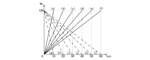
- 4 is a diagram showing the relationship between the distance from the periphery 74 in the connection region 75 in FIG. 2 and the density of dots of the ink 41.
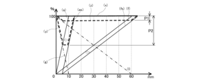
- FIG. 4 is a diagram showing a schematic representation of the total amount of ink when the connection area 75a and the connection area 75b shown in FIG. 3 overlap each other.
- FIG. 4 is an example of a printed image of a printed matter 70 according to the first embodiment.
- 4 is an example of a printed image of a printed matter 70 according to the first embodiment.
- FIG. 4 is an enlarged schematic diagram of a print image area 71 according to the first embodiment.
- FIG. 4 is an enlarged schematic diagram of a print image area 71 according to the first embodiment.
- FIG. 1 is a side view illustrating an example of a printing device 100 according to a first embodiment. 1 is a cross-sectional view showing an example of a printing pad 10 provided in a printing device 100 according to a first embodiment. 4 is a flow chart showing a method for producing a printed matter by the printing device 100 according to the first embodiment. 4 is a flow of an operation of the printing device 100 according to the first embodiment. 10 is a modified example of the printing pad 10 used in the printing device 100 of the first embodiment.
- Embodiment 1 The following describes the printed matter and the method for manufacturing the printed matter according to the present invention with reference to the drawings. Note that the present invention is not limited to the embodiments described below. Also, the same parts in each drawing are given the same reference numerals, and some explanations are omitted. Also, each drawing is a schematic drawing, and the present invention is not limited to the shapes shown in the drawings.
- FIG. 1 is an explanatory diagram of a cross-sectional structure of a printed matter 70 according to the first embodiment.
- the printed matter 70 is, for example, a resin molded product having a plurality of printed image areas 71 on at least one surface 70a of a base 76.
- the printed image areas 71 of the printed matter 70 form, for example, a predetermined pattern, design, color, or the like.
- the printed image areas 71 may also be applied to a resin molded product constituting an exterior cover of an illumination device such as an automobile tail lamp or headlight, and suppress light transmission.
- the shape of the printed matter 70 shown in FIG. 1 is an example, and the shapes of the surfaces 70a and 70b can be changed as appropriate.
- the printed matter 70 in FIG. 1 has four printed image areas 71 arranged on the surface 70a, as an example.
- the two adjacent printed image areas 71A and 71B have their peripheries 74A and 74B arranged within the range of the other printed image area 71A or 71B.
- the two adjacent printed image areas 71A and 71B have their peripheries 74A and 74B in contact with each other, or have portions of the areas including the peripheries 74A or 74B overlapping each other.
- the end area of the printed image area 71A that includes the periphery 74A is called the connection area 75A.
- the end area of the printed image area 71B that includes the periphery 74B is called the connection area 75B.
- the peripheries 74A and 74B may be collectively referred to as the periphery 74.
- the connection regions 75A and 75B may be collectively referred to as the connection region 75.
- FIG. 2 shows an example of a connection region 75 in a print image region 71 of a printed matter 70 according to embodiment 1.
- the connection region 75 is configured so that the amount of ink per unit area gradually increases, for example, from the periphery 74 toward the center of the print image region 71.
- FIG. 3 is a diagram showing the relationship between the distance from the periphery 74 in the connection area 75 in FIG. 2 and the density of ink 41 dots.
- the connection area 75 is configured so that the amount of ink gradually increases from the periphery 74 toward the center of the print image area 71, and in FIG. 3, the amount of ink in the center of the print image area 71 is 100%, and the amount of ink at the periphery 74 is 0%.
- the solid lines (a)-(f) in FIG. 3 represent the density of ink 41 in the connection area 75A of one of two adjacent print image areas 71A, for example. Meanwhile, the dashed lines (g)-(l) in FIG. 3 represent the density of ink 41 in the connection area 75B of the other print image area 71B.
- Two adjacent print image areas 71A and 71B are configured so that the gradient of the ink 41 dot density in the connection area 75 is, for example, a combination of the solid line (a) and the dashed dot line (g).
- print image areas 71A and 71B are configured so that the change in ink 41 dot density with respect to the distance from the periphery 74 of the connection area 75 is substantially the same.
- the difference in the ink 41 dot density in the connection area 75 with the center of the print image area 71 is small, and the boundary L between the two print image areas 71 is less noticeable.
- print image areas 71A and 71B are printed so that they ideally overlap by the same width as the connection area 75.
- the graph of the change in dot density of ink 41 in the connection area 75 shown in FIG. 3 represents the ratio of the ink amount when the ink amount in the center is set to 100%, but the image applied to the print image area 71 is not limited to a single-color uniform pattern as shown in FIG. 2.
- the image applied to the print image area 71 may be, for example, a multicolor uneven pattern such as a wood grain pattern, a painting, or a photograph.
- the ink amount ratio [%] shown in FIG. 3 represents the ratio of the ink amount to the original image, with the state in which the connection area 75 is printed with the same ink amount as the center being set to 100%.
- the connection areas 75 of two adjacent print image areas 71 are configured so that the image gradually becomes thinner toward the periphery 74 than the original image.
- FIG. 4 is a schematic diagram showing the total ink amount when the connection area 75a and the connection area 75b shown in FIG. 3 overlap.
- the total ink amount of the connection area 75 is substantially uniform throughout, as shown by the thick solid line (x).
- the connection area 75a shown by the solid line (a) and the connection area 75b shown by the dashed line (g) overlap the total ink amount of the connection area 75 is substantially uniform throughout, as shown by the thick solid line (x).
- the ink 41 dot density may not be completely uniform, as shown by the solid line (x) in Figure 3.
- the solid line (fs) in FIG. 4 shows the change in dot density of ink 41 in connection area 75 versus distance from edge 74 when one of the printed image areas 71 is printed shifted from its original position.
- the solid line (fs) shows a state in which one of the printed image areas 71 is shifted 5 mm from its original ideal position.
- the solid line (fs) shows a case in which the two connection areas 75 are originally formed to overlap by 60 mm, but are overlapped by 55 mm.
- connection area 75A represented by the solid line (fs) and connection area 75B represented by the dot-dash line (l) are overlapped to form the dot density distribution of ink 41 represented by the dashed line (z), resulting in an area with a low dot density of up to approximately 8%.
- the solid line (as) in FIG. 4 indicates the change in dot density of ink 41 in connection area 75 versus distance from edge 74 when one of the printed image areas 71 is printed shifted from its original position.
- the solid line (as) indicates a state in which one of the printed image areas 71 is shifted 5 mm from its original ideal position.
- the solid line (as) indicates a case in which the two connection areas 75 are overlapped by only 5 mm, whereas they are originally formed to overlap by 10 mm.
- connection area 75A represented by the solid line (as) and the connection area 75B represented by the dashed line (g) are overlapped, resulting in a dot density distribution of ink 41 represented by the dashed line (y), with an area of low dot density of up to approximately 50%.
- connection area 75 As can be seen by comparing the solid line (fs) and the solid line (as) in Figure 4, it is desirable for the connection area 75 to be as wide as possible, and for the slope of the change in dot density of the ink 41 to be gentle. As shown by the solid line (fs) in Figure 4, by making the connection area 75 relatively large and increasing the area where two adjacent print image areas 71 overlap, the change in dot density of the ink 41 near the boundary L between the two print image areas 71 can be kept small. This improves the quality of the print image even in a printed matter 70 that is manufactured by combining multiple print image areas 71 through multiple printing processes, for example as shown in Figure 1.
- the printed matter 70 shown in FIG. 1 has a width of one print image area 71 of approximately 500 mm, and a connection area 75 of approximately 30 mm. This is because the range of the maximum print image area 71 is determined by the size of the printing device 100, the printing pad 10, or the size of the printing plate 50.
- the print image shown in FIG. 5 is an example of a print image of a printed matter 70 according to the first embodiment.
- the print image shown in FIG. 5 has a first region 72 having a relatively large amount of ink 41 per unit area, and a second region 73 having a relatively small amount of ink 41.
- the first region 72 has a larger amount of ink 41 per unit area than the second region 73.
- a plurality of first regions 72 are arranged, each surrounded by a second region 73.
- the print image shown in FIG. 5 is composed of two print image regions 71A and 71B, and the boundary L between the two print image regions 71A and 71B is arranged to avoid the first regions 72A and 72B.
- the periphery 74 of the print image region 71 is arranged within the second region 73.
- the region in the print image region 71A having a relatively small amount of ink 41 is called the second region 73A
- the region in the print image region 71B having a relatively small amount of ink 41 is called the second region 73B.
- the printed image shown in FIG. 6 is a wood grain pattern, in which a first region 72 having a relatively dark color and a second region 73 having a relatively light color extend in the vertical direction of the figure, and are arranged in a striped pattern that is alternately arranged.
- the printed image shown in FIG. 6 is composed of two printed image regions 71A and 71B, and the boundary L between the two printed image regions 71A and 71B is arranged in the first region 72. In other words, the periphery 74 of the two printed image regions 71 is arranged within the first region 72.
- the periphery 74A and 74B of each of the two printed image regions 71A and 71B are configured in a curved shape having unevenness, and are arranged within the range of the other of the two printed image regions 71A and 71B. Since the boundary L is arranged along the striped pattern, it is less noticeable by being arranged in the first region 72 having a dark color. In addition, by configuring the connection area 75, which includes the periphery 74 of the print image areas 71A and 71B, so that the dot density of the ink 41 gradually increases toward the center as shown in FIG. 2, the boundary L becomes less noticeable.
- the boundary L between the print image areas 71A and 71B may be provided in the second area 73, which is relatively light in color. In either case, by providing the boundary L in either the first area 72 or the second area 73, it is positioned along either the dark area or the light area of the striped pattern, making it less noticeable.
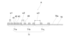
- FIG. 7 and 8 are enlarged schematic diagrams of a print image area 71 according to the first embodiment.
- FIG. 7 is a schematic cross-sectional diagram of a case where ink 41 is arranged in dots on one surface 70a of a printed matter 70.
- FIG. 8 is a plan view of the print image area 71 in FIG. 7.
- the print image area 71 is formed by placing ink 41 on one surface 70a of the printed matter 70.
- the area on one surface 70a of the printed matter 70 where the ink 41 is placed is referred to as the print image area 71.
- the surface 70a on which the print image area 71 is placed includes a first portion 42 which is a surface on which the ink 41 is placed, and a second portion 43 which is a surface on which the ink 41 is not placed.
- the print image area 71 may include a plurality of print image areas 71a, 71b, and 71c having different arrangement densities of the first portion 42 on which the ink 41 is placed.
- the ink 41 is arranged at intervals w1 in the cross section.
- the ink 41 is arranged at intervals w2.
- the ink 41 is arranged at intervals w3.
- the intervals at which the ink 41 is arranged in each of the print image areas 71a, 71b, and 71c are different, and are set to w1 ⁇ w2 ⁇ w3.
- the print image area 71 is not limited to a form in which dots of the ink 41 are distributed as in the print image areas 71a, 71b, and 71c, and the ink 41 may be arranged over the entire area of a predetermined area.
- the multiple printed image regions 71a, 71b, and 71c each have a different density of ink 41.
- the ink 41 is disposed at a substantially uniform density in each of the multiple printed image regions 71a, 71b, and 71c.
- the area in which the ink 41 is disposed is the same in each of the multiple printed image regions 71a, 71b, and 71c, regardless of which part of the region having a certain area is observed.
- the non-printed region is a region in which the ink 41 is not disposed, or in other words, a region in which the density of the ink 41 is disposed is zero.
- the ink 41 (first portion) is arranged in the x direction and the y direction, and the number of ink 41 arranged per unit area, that is, the arrangement density, is different.
- the arrangement density of the ink 41 in the printed image area 71a is higher than the arrangement density of the ink 41 in the printed image area 71b and the printed image area 71c.
- the arrangement density of the ink 41 in the printed image area 71b is higher than the arrangement density of the ink 41 in the printed image area 71c.
- a printed image area 71 having a lower arrangement density of the ink 41 than the first printed area may be referred to as a second printed area.
- the printed matter 70 according to the first embodiment has a printed image area 71, and the printed image area 71 may include a plurality of printed image areas 71a, 71b, and 71c having different arrangement densities of the ink 41.
- the multiple printed image areas 71a, 71b, and 71c include a first printed area in which the arrangement density of the first portions 42 is higher than that of the second printed area.
- the second printed area has a higher density of the second portions 43 in which the ink 41 is not placed than the first printed area.
- the printed matter 70 has a plurality of print image areas 71a, 71b, and 71c with different ink 41 placement densities, and may be configured such that the connection area 75 including the periphery 74 is composed of a plurality of print image areas 71a, 71b, and 71c with different ink 41 placement densities, as shown in FIG. 2 to FIG. 4.
- the plurality of print image areas 71 may be formed by a plurality of printing processes, and may be printed by overlapping the second print areas with a low ink 41 placement density. For example, in the printed matter 70 shown in FIG.
- the print image area 71b, which is a part of one print image area 71A, and the print image area 71c, which is a part of the other print image area 71B, are printed so as to overlap
- the print image area 71c, which is a part of one print image area 71A, and the print image area 71b, which is a part of the other print image area 71B, are printed so as to overlap.
- the print image areas 71b and 71c which have different ink 41 density, overlap, so that the overall image formed by combining the two print image areas 71 has a uniform ink 41 density.
- the print image area 71 described here is used when the print image area 71 formed on the printed matter 70 is formed by multiple printing processes, that is, when the print range is wide or the surface shape of the printed matter 70 is complex. This makes it possible to form the print image area 71 without any gaps between adjacent print image areas 71 and without any unevenness overall.
- the variation in the printing position of each print image area 71 caused by multiple printing processes can be absorbed by overlapping the print image areas 71b and 71c, which have a low ink 41 density, and the print image area 71 can be formed without any unevenness overall.
- the print image area 71a that is not overlapped is called the first print area
- the print image areas 71b and 71c that are overlapped in the above description are called the second print area.
- the two adjacent print image areas 71 have second print areas with a low ink 41 arrangement density like print image areas 71b and 71c on the periphery of each print image area 71, and by overlapping each second print area, the boundary between the two print image areas 71 can be printed so that it is not noticeable.
- the second print area may be composed of multiple print image areas with different ink 41 arrangement densities like print image areas 71b and 71c, or it may be composed of even more print image areas. Furthermore, the second print area is not limited to the one in which the density of the ink 41 is changed stepwise as shown in Figures 7 and 8, but may be configured so that the density of the ink 41 decreases continuously from the center to the periphery of the print image area 71.
- the visible surface has a three-dimensional surface structure, such as the substrate 76 of the printed matter 70 shown in FIG. 1, it is desirable that the overlapping portions of the second printing regions of the two adjacent printing regions as described above are located at a position where the ink 41 from the printing pad 10 can be transferred as accurately as possible. Therefore, it is preferable that the overlapping portions of the second printing regions are located so as to include a portion of the three-dimensional surface structure that has a tangent perpendicular to the pressing direction in a cross section parallel to the pressing direction of the printing pad 10. In FIG. 1, for example, when the printing image regions 71A and 71B are overlapped, the central connection region 75 is most preferable.
- connection region 75 may be located within a range in which the tangent H forms an angle of 0° to 30° with respect to the surface perpendicular to the pressing direction.
- the connection regions 75 located on the leftmost and rightmost sides in FIG. 1 are also practically problem-free. If the angle of the tangent line H of the portion where the connection region 75 is located with respect to a plane perpendicular to the pressing direction is large, it is advisable to position the base 76 at an angle so that the tangent line H is substantially perpendicular to the pressing direction of the printing pad.
- the ink 41 is shown as a rectangular dot in plan view, but this is a schematic representation, and in reality, the ink may be circular or have a shape close to that in plan view. Also, in Figures 7 and 8, the ink 41 is shown as a rectangle, but this is also a schematic representation, and in reality, the ink may be rounded, for example, like a droplet placed on a water-repellent surface.
- the placement density of the ink 41 in each of the print image areas 71a, 71b, and 71c is uniform within each of the print image areas 71a, 71b, and 71c, but is not limited to this.
- the placement density of the ink 41 may be changed continuously so that it gradually decreases from left to right in FIG. 8.
- ⁇ Printing device 100> 9 is a side view showing a schematic example of a printing device 100 according to the first embodiment.
- the printing device 100 includes a printing pad 10 that is movable linearly in the vertical direction.
- the printing pad 10 is moved up and down by a vertical movement device 11 included in the printing device 100, and the printing surface 4 is pressed against the surface to be printed of the printed matter 70.
- the surface to be printed is surface 70a.
- the printing device 100 also includes a horizontal movement device 12.
- the horizontal movement device 12 moves the printing pad 10 and the vertical movement device 11 in the horizontal direction.
- the printing pad 10 is moved by the horizontal movement device 12 above the printed matter 70, the cleaning device 60, the activation device 61, the air blow device 62, or the printing plate 50.
- the printing pad 10 is moved up and down by the vertical movement device 11, and the printing surface 4 is pressed against the printed matter 70, the cleaning device 60, the activation device 61, or the printing plate 50, respectively.
- the printing device 100 has, from the left side, a printing stage 87 on which the printed matter 70 is placed, a surface treatment stage 86 equipped with a cleaning device 60, and a printing plate stage 85.
- the surface treatment stage 86 is equipped with an activation device 61 and an air blow device 62.
- the printing plate stage 85 is where the printing plate 50 is placed.
- these stages can be freely arranged and can be changed as appropriate according to the convenience of the operator and the location where the printing device 100 is installed.
- the cleaning device 60, activation device 61, air blow device 62, and blowers 66 and 66A of the printing device 100 may not be installed on the printing device 100.
- FIG. 10 is a cross-sectional view showing an example of the printing pad 10 provided in the printing device 100 according to the first embodiment.
- FIG. 10 shows a cross section passing through the top 6 of the printing pad 10 and perpendicular to the plane 13 to which the substrate 5 is fixed.
- the substrate 5 of the printing pad 10 includes an internal layer 1 and an external layer 2 covering the surface of the internal layer 1.
- the printing pad 10 shown in FIG. 10 is, for example, substantially hemispherical.
- the shape of the printing pad 10 is not limited thereto, and can be changed as appropriate according to the specifications of the printed matter 70, such as a bullet shape, a shape having a curved surface formed by rotating a parabola around its symmetrical axis, a shape of a part of an ellipsoid cut, a shape in which a bullet-shaped or semicircular cross section is continuously extended in a straight line, etc.
- the printing pad 10 includes a top 6 that first comes into contact with the printed matter 70 or the printing plate 50, and the top 6 is composed of a point or a line. As a result, when the printing pad 10 is pressed against the printed matter 70 or the printing plate 50, air is not trapped between the printing surface 4 and the printed matter 70 or the printing plate 50.
- a predetermined range of the surface of the printing pad 10, centered on the apex 6, becomes the printing surface 4 that picks up ink from the printing plate 50 and transfers it to the printed matter 70.
- the printing pad 10 is shown forming one print image area 71 on the printed matter 70 in one printing process, and four printing processes are performed to produce the printed matter 70.
- the substrate 5 is formed by molding, for example, silicone rubber.
- the substrate 5 has elasticity (flexibility) and is mixed with silicone oil to make it easily deformable.
- the substrate 5 has a substantially hemispherical shape, but the shape can be appropriately changed according to the specifications of the printed matter 70.
- the substrate 5 deforms when the printing pad 10 is pressed against the printing plate 50, and transfers the ink 41 placed on the placement surface 51 of the printing plate 50 to the printing surface 4.
- the ink 41 placed on the placement surface 51 of the printing plate 50 is arranged in correspondence with the image to be printed on the printed matter 70, and forms a printing pattern according to the image.
- the material of the substrate 5 is not limited as long as it can transfer the ink 41 to the printed surface when the printing pad 10 is pressed against the printed surface.
- the substrate 5 may be formed from two materials with different hardnesses.
- the material of the outer layer 2 constituting the portion close to the printing surface 4 is set to an Asker C hardness range of 5 to 20 points.
- the material constituting the inner layer 1 inside the outer layer 2 is set to an Asker C hardness range of 20 to 40 points.
- the inner layer 1 is located on the side where a force is applied to press the printing surface 4 against the surface to be printed during printing, and is located closer to the support member 7 than the outer layer 2.
- the support member 7 is connected to the vertical movement device 11 and is a part that transmits the force from the vertical movement device 11 to the printing pad 10. In FIG.
- the upper portion of the substrate 5 has an Asker C hardness set to 20 to 40 points
- the lower portion of the substrate 5 (the side where the apex 6 is located) has an Asker C hardness set to a range of 5 to 20 points.
- the hardness of the printing pad 10 is set lower at the portion on the printing surface 4 side that is pressed against the printed matter 70 than at the upper portion. This configuration makes it easier for the printing pad 10 to maintain its overall shape.
- the outer layer 2 that is pressed directly against the surface to be printed has the advantage that it is easy to deform into the three-dimensional shape of the surface to be printed.
- the hardness of each portion of the substrate 5 is not limited to the above hardness.
- a surface treatment stage 86 is disposed next to a printing stage 87 of the printing device 100.
- a cleaning device 60 is disposed on the surface treatment stage 86.
- the cleaning device 60 includes, for example, paper or adhesive tape. The printing surface 4 of the printing pad 10 is pressed against the surface of the paper or adhesive tape to remove ink 41, dirt, dust, and the like remaining after printing.
- the activation device 61 includes a storage tank for storing liquid and an absorption unit for absorbing and retaining the liquid.
- the printing surface 4 of the printing pad 10 is pressed against the surface of the absorption unit, so that the liquid retained by the absorption unit adheres to the printing surface 4.
- the printing pad 10 makes it easier to transfer the ink 41 placed on the printing plate 50 to the printing surface 4 by adhering or soaking the substrate 5 with water or a solvent.
- the liquid is appropriately selected according to the properties of the components contained in the ink 41, and has the property of softening the hard ink 41.
- the ink 41 is a mixture of synthetic resins such as acrylic resin or urethane resin, and water, thinner, xylene, or toluene, and it is preferable to select a liquid that has a high affinity with the solvent contained in the ink 41.
- the liquid used in the activation device 61 is not limited to the above.
- the absorption unit of the activation device 61 is composed of, for example, a thin sheet-like absorbent material stacked on top of each other.
- the absorbent material is composed of, for example, paper, but is not limited to paper and may be composed of other materials such as cloth or resin as long as it absorbs liquid.
- the absorption unit may be composed of paper stacked on top of a sponge-like resin.
- the surface of the absorption unit against which the printing surface 4 of the printing pad 10 is pressed may be contaminated with ink 41 remaining on the printing surface 4 of the printing pad 10, or the surface of the absorption unit may be scraped, causing the paper constituting the absorption unit to tear.
- the paper located in the topmost layer of the absorption unit is peeled off and removed from the topmost layer of the absorption unit, and the upper layer can be removed one by one from the stack, or mechanically replaced.
- the method of replacing the paper located in the topmost layer is not limited to this method.
- the absorption unit is designed so that the top layer of paper and other materials can be removed or replaced as needed, and the surface is always kept clean and permeated with liquid, so the printing surface 4 of the printing pad 10 can be activated by pressing it against it.
- Air blow device 62 adjusts the amount of water or solvent attached to the printing surface 4 of the printing pad 10 by the activation device 61 to an appropriate amount.
- the air blowing device 62 blows air toward the printing surface 4 to remove excess water or solvent from the printing surface 4. Note that the type and number of the air blowing devices 62 and the direction in which the air is blown are not limited.
- the printing plate stage 85 has the printing plate 50 placed on its upper surface, and is equipped with an ink placement device 63 that places ink on the printing plate 50.
- the ink placement device 63 includes, for example, a roller 64 that holds ink, and the roller 64 rolls over the printing plate 50 to place the ink on the printing plate 50.
- the ink placement device 63 may also be an inkjet head that is installed so as to be movable in the horizontal direction. In this case, the head places ink on the surface of the printing plate 50 by an inkjet method, and is configured so as to be movable along a moving rail.
- the ink placement device 63 is not limited to the above and may take other forms.
- Fig. 11 is a flow chart of a method for producing a printed matter by the printing device 100 according to the first embodiment. The method for producing a printed matter by the printing device 100 will be described below with reference to Figs. 9 and 11.
- the printing device 100 includes a control device 20.
- the control device 20 is formed of, for example, a microcomputer, and includes a calculation device 20a and a storage device 20b. The functions of the control device 20 are realized using the calculation device 20a and the storage device 20b (see Fig. 9).
- the storage device 20b is a ROM that holds programs and data in advance, a RAM for temporarily storing data when a program is executed, etc.
- a non-volatile or volatile semiconductor memory such as a flash memory, an EPROM (Erasable and Programmable ROM), and an EEPROM (Electrically Erasable and Programmable ROM) may be used.
- a removable recording medium such as a magnetic disk, a flexible disk, an optical disk, a CD (Compact Disc), an MD (Mini Disc), and a DVD (Digital Versatile Disc) may be used.
- the storage device 20b can store information obtained from the temperature sensor 68, etc., and information processed in the calculation device 20a.
- the arithmetic unit 20a performs various processes to execute the functions of the control unit 20.
- the arithmetic unit 20a compares room temperature information, for example from a temperature sensor, with a temperature threshold value previously stored in the storage unit 20b to determine whether the room temperature is higher than the threshold value. If the room temperature is higher than the threshold value, the control unit 20 controls the output of the heater in the blower 66 to a predetermined value. Alternatively, if the room temperature is higher than the threshold value, the control unit 20 may control the blower 66 to be shorter in operation. Alternatively, the control unit 20 may control the printing pad 10 to stop in front of the blower 66 and limit the time it is exposed to air.
- a printing plate preparation step OP1 is first performed in which a print image is formed on a mounting surface 51 of a printing plate 50.
- the printing plate 50 has a flat plate shape and is placed on the printing plate stage 85.
- the printing plate 50 is a thin flat plate made of an aluminum alloy.
- the resin layer on the surface is made of a layer that repels ink and a layer that repels ink.
- the ink placement device 63 is horizontally moved at least above the printing plate 50 by a feed device (not shown).
- the printing plate 50 may be configured to be movable relative to the ink placement device 63. As shown in FIG.
- the printing plate preparation process OP1 has a similar configuration.
- a "grass receiving sheet” is used because of its retention and affinity with UV ink. Rich sheet material may also be used.
- the surface of the printing plate 50 is finished to a predetermined surface roughness.
- the printing device 100 using the inkjet method is as follows: Fine ink droplets are ejected from nozzles provided in a head serving as an ink depositing device 63, and are sprayed onto the printing plate 50 to obtain a print image.
- the head may be configured to eject ink of four colors, for example, red, blue, yellow, and black.
- the head is provided with a storage section for storing intermediate color inks having four intermediate colors and a nozzle for ejecting the intermediate color inks.
- the head prints dots of inks of at least five different colors including the intermediate color inks on the printing plate 50. It may be configured to be disposed on the surface.
- Ink drying process OP2 After the printing plate creating process OP1 is completed, the ink drying process OP2 is performed.
- the ink drying process OP2 is performed in the case of printing by the inkjet method.
- the ink drying process OP2 may be omitted, or a drying process of the ink 41 transferred to the surface of the printing pad 10 may be provided between the transfer process OP3 and the pressing process OP4 instead of the ink drying process OP2.
- the ink 41 on the printing plate 50 has a low viscosity.
- the ink 41 on the printing plate 50 If the viscosity of the ink 41 on the printing plate 50 remains low, the ink 41 will be crushed and will not be transferred with good accuracy when the printing pad 10 is pressed against the ink 41 on the printing plate 50. In addition, the accuracy of the printed image will decrease due to bleeding of the ink 41, etc. Therefore, in the ink drying process OP2, the solvent contained in the ink 41 is evaporated to increase the viscosity of the ink 41.
- the ink 41 on the printing plate 50 is ventilated or heated to evaporate the solvent in the ink 41.
- the printing plate 50 may be left on the printing plate stage 85 and allowed to dry naturally for a predetermined time.
- the solvent is more volatile than the other components in the ink 41.
- the viscosity of the ink is increased by evaporating the solvent from the ink 41 using a means such as ventilating, and increasing the proportion of components other than the solvent in the ink 41.
- the viscosity of the ink 41 is adjusted to, for example, 3 Pa ⁇ s to 1000 Pa ⁇ s. It is desirable to match the time required for drying the ink to the time required for the subsequent transfer process OP3 and pressing process OP4. By configuring in this way, a large number of printed matter 70 can be printed efficiently in succession.
- the printing plate 50 may be moved from the printing plate stage 85, or may remain placed on the printing plate stage 85. If the printing plate 50 is moved from the printing plate stage 85, another printing plate 50 can be immediately placed on the printing plate stage 85 and the printing plate creation process OP1 can be started, which has the advantage of shortening the cycle time of the entire offset printing process.
- the ink 41 on the printing plate 50 may be dried, for example, by installing a blower and a heater next to the ink placement device 63 and sending air that has passed through the heater onto the printing plate 50 using the blower.
- the heater installed together with the blower is set to a temperature that is as high as possible but below the boiling point of the solvent contained in the ink 41.
- the solvent contained in the ink 41 is selected to be semi-dried in the ink drying process OP2.
- a solvent is selected that has a flash point of 40°C or higher and a boiling point of 120°C or higher.
- the heater temperature is set to, for example, 100°C. Note that a solvent with high dissolving power may damage the ink placement device 63, so a solvent with low dissolving power is desirable.
- the ink 41 used in the printing device 100 is not limited to the above.
- Transfer process OP3 In the transfer step OP3, when printing is performed using a printing pad 10 having a curved surface such as a parabolic shape, the printing pad 10 is pressed from its apex against the printing plate 50 to transfer the print image. As described above, after the transfer step OP3, an ink drying step OP6 may be performed in which the ink 41 transferred to the printing pad 10 is dried. This ink drying step OP6 corresponds to the drying step S3 described in the operation of the printing device 100 described below.
- pressing process OP4 In the pressing step OP4, the printing pad 10 is pressed against the print object 70. The ink 41 adhering to the surface of the printing pad 10 is transferred to the surface of the print object 70. When printing is performed using the printing pad 10, even if the surface of the print object 70 has a curved surface, printing can be performed by following the shape of the surface. Note that the base 76 is positioned on the printing stage 87 before the pressing step OP4 is performed. The positioning of the base 76 is performed using a jig 89.
- the pressing step is performed multiple times on the print object 70, it is preferable to change the jig 89 each time to change the posture of the print object 70 and adjust so that the printing pad 10 is pressed against the surface of the base 76 at a desired position and angle.
- the ink 41 transferred onto the surface of the printed matter 70 in the pressing step OP4 is fixed.
- the surface of the printed matter 70 may be irradiated with ultraviolet rays by an ultraviolet irradiation device (not shown) to harden the ink 41.
- an electron beam may be irradiated instead of ultraviolet rays.
- an ultraviolet irradiation device 80 that can irradiate ultraviolet rays along the curved surface.
- the method is not limited to curing the ink 41 by irradiating it with ultraviolet light or an electron beam, and other methods may be used, such as curing the ink 41 by heating it with a heater or drying it by blowing air. Furthermore, the ink 41 may be cured by natural drying.
- Fig. 12 is a flow chart showing the operation of the printing device 100 according to embodiment 1.
- the printing device 100 operates according to the flow shown in Fig. 12.
- the start process is a process performed immediately after starting the printing device 100.
- the surface of the printing pad 10 may not be activated immediately after starting the production of printed matter, so a process is performed to properly activate the printing surface 4 of the printing pad 10.
- the printing device 100 moves the printing pad 10 above the activation device 61 and lowers it toward the activation device 61.
- the printing pad 10 is raised after the printing surface 4 is pressed against the absorption unit of the activation device 61 and a predetermined range including the printing surface 4 comes into contact with the absorption unit. This is called the activation process (SP1).
- liquid such as water or solvent that has soaked into the absorption unit of the activation device 61 adheres to or soaks into the printing surface 4 of the printing pad 10.
- the printing pad 10 has unevenness formed on its surface and soaks into the absorption unit. This process is called the first start process.
- the printing device 100 After the first start step is completed, it is determined whether the amount of liquid adhering to the printing surface 4 of the printing pad 10 is appropriate (SP2). If the amount of liquid adhering to the printing surface 4 is not appropriate (NO in SP2), the printing device 100 performs the air blowing step (SP3). In the air blowing step, the air blowing device 62 blows air onto the printing surface 4 of the printing pad 10 to remove excess liquid adhering to the printing surface 4. Note that when the amount of liquid adhering to the printing surface 4 is not appropriate, this refers to when there is an excessive amount of liquid adhering to the printing surface 4. The above steps are referred to as the second start step.
- the printing device 100 After completing the second start step, it is determined whether the amount of liquid adhering to the printing surface 4 of the printing pad 10 is appropriate (SP4). If excess water or solvent is still adhering to the printing surface 4 of the printing pad 10 (NO in SP4), the printing device 100 performs the absorption step (SP5). In the absorption step, the printing device 100 presses the printing surface 4 of the printing pad 10 against the cleaning device 60. This removes the excess liquid adhering to the printing surface 4 of the printing pad 10. The above steps are referred to as the third start step.
- one or both of the air blowing step (SP3) and the absorbing step (SP5) may be omitted.
- the order of the air blowing step and the absorbing step may be changed.
- the air blowing step (SP3) and the absorbing step (SP5) of the starting step may be performed multiple times.
- the repeat step includes an ink placement step (S1), an ink transfer step (S2), a drying step (S3), a pressing step (S4), a cleaning step (S5), an activation step (S6), an air blow step (S8), and an absorption step (S10).
- the printing device 100 advances the steps in the order of the ink placement step (S1), the ink transfer step (S2), the drying step (S3), the pressing step (S4), the cleaning step (S5), the activation step (S6), the air blow step (S8), and the absorption step (S10).
- the repeat step is not limited to this order.
- the printing device 100 performs the drying step (S3) to the absorption step (S9).
- the printing apparatus 100 may perform the next ink depositing step (S1) in parallel while the drying step (S3) through the absorbing step (S9) are being performed.
- the ink placement step (S1) corresponds to the printing plate creation step OP1 in the method for producing a printed matter shown in FIG. 11.
- the ink transfer step (S2) corresponds to the transfer step OP3 in the method for producing a printed matter shown in FIG. 11.
- a drying step (S3) may be performed in which air is blown onto the printing surface 4 of the printing pad 10 to increase the viscosity of the ink 41 on the printing surface 4.
- the drying step (S3) is performed by blowing air onto the printing surface 4 of the printing pad 10 using the blower 66 of the printing stage 87.
- the drying step (S3) may also be performed using the blower 66A on the surface treatment stage 86.
- the drying step (S3) may or may not be performed depending on the viscosity of the ink 41 on the printing plate 50.
- the pressing step (S4) corresponds to the pressing step OP4 in the method for producing a printed matter shown in FIG. 11.
- a process of moving the printing pad 10 above the base 76 is included between the ink transfer process (S2) and the pressing process (S4).
- the process including the ink transfer process (S2), the process of moving the printing pad 10 above the base 76, and the pressing process (S4) may be referred to as the printing process.
- one print image area 71 is completed each time the pressing step (S4) is performed.
- the pressing step (S4) is performed four times while changing the position of the printing pad 10.
- the cleaning step (S5) the printing surface 4 of the printing pad 10 after the ink 41 has been transferred to the printing surface is pressed against a flat cleaning surface of the cleaning device 60.
- the ink 41 remaining on the printing pad 10 is adhered to the cleaning surface.
- the cleaning surface is made of paper or adhesive tape, but is not limited to these.
- the activation step (S6) is the same as the activation step (SP1) in the start step.
- the air blow step (S8) is the same as the air blow step (SP3) in the start step.
- the absorption step (S10) is also the same as the absorption step (SP5) in the start step.
- the air blow step (S8) and the absorption step (S10) are performed according to the amount of liquid such as water or solvent adhering to the printing surface 4 of the printing pad 10, and one of them may be omitted, or at least one of them may be performed multiple times.
- the air blow step (S8) and the absorption step (S10) are performed according to the activation state of the printing surface 4 after checking the state of the printing surface 4 of the printing pad 10 before each step.
- the state of the printing surface 4 of the printing pad 10 is confirmed, and if the activation state of the printing surface 4 is appropriate, it is determined in the repeat judgment step (S11) whether or not to perform printing again. If printing is to be performed again (YES in S11), the ink depositing step (S1) and subsequent steps are repeated. If printing is not to be repeated (NO in S11), the production of the printed matter is terminated.
- the printing device 100 performs a start process when started up, and then repeats the process to print on a large number of printed materials 70. Note that if the printing pad 10 is in an activated state, the above start processes (SP1 to SP5) may be omitted.
- FIG. 13 is a modified example of the printing pad 10 used in the printing device 100 of embodiment 1.
- the printing pad 10 according to embodiment 1 may have a protective coating layer 3 that covers the surface of the substrate 5.
- the protective coating layer 3 constitutes the outer printing surface 4 of the printing pad 10.
- the protective coating layer 3 is formed, for example, by attaching a 0.5 mm silicone rubber sheet to the surface of the outer layer 2.
- the protective coating layer 3 prevents the silicone oil contained in the soft silicone rubber inside from seeping out onto the printing surface 4.
- the outer surface of the protective coating layer 3 constitutes the printing surface 4 and is repeatedly pressed against the printing plate 50 and the surface to be printed, so it needs to be durable against scratches and wear.
- the protective coating layer 3 uses a material that is harder than the outer layer 2, and is thin so that the printing surface 4 follows the surface to be printed when pressed against the surface to be printed.
- the thickness of the protective coating layer 3 is configured to be as thin as possible, and may be configured to be in the range of 0.1 mm to 1 mm, for example.
- the material of the protective coating layer 3 is not limited to silicone rubber, and any material can be selected as long as it follows the deformation of the inner layer 1 and the outer layer 2.
- it is desirable that the protective coating layer 3 has sufficient elasticity so that it can be attached along the surface of the substrate 5 in the process of attaching the protective coating layer 3 to the substrate 5.
- the printing pad 10 may be further formed into a multi-layer structure.
- the inner layer 1 or the outer layer 2 of the printing pad 10 shown in FIG. 13 may be further formed into a multi-layer structure using materials with different hardness.
- the protective coating layer 3 is attached to the surface of the substrate 5, but when it is damaged, such as scratched or worn, it can be peeled off from the surface of the substrate 5 and replaced with a new one.
- the protective coating layer 3 is less expensive than the substrate 5, and the substrate 5 inside can be used as is by replacing it. Therefore, by updating the protective coating layer 3, the expensive substrate 5 can be used repeatedly, and the state of the printing surface 4 of the printing pad 10 can be kept suitable for printing.
- the printing device 100 according to the first embodiment can reduce the cost of printing.
- the substrate 5 is composed of the internal layer 1 and the external layer 2, but it may be composed of only one layer of the internal layer 1.
- the protective coating layer 3 may be provided on the substrate 5 formed of only one layer of the internal layer 1.
- the substrate 5 when replacing the protective coating layer 3 attached to the substrate 5, the substrate 5 may be scratched by the peeling operation of the protective coating layer 3, or the surface of the substrate 5 may be altered, such as becoming hard. Therefore, it is desirable for the substrate 5 to be constructed in multiple layers as shown in FIG. 13.
- the present invention has been described above based on the embodiments, but the present invention is not limited to the configurations of the above-mentioned embodiments.
- the combination of components is not limited to the combinations in the embodiments, but can be modified as appropriate.
- we would like to emphasize that the gist (technical scope) of the present invention also includes the scope of various modifications, applications, and uses that a person skilled in the art may make as necessary.
- Printing Print image area 71A print image area, 71B print image area, 71a print image area, 71b print image area, 71c print image area, 72 first area, 72A first area, 72B first area, 73 second area, 73A second area, 73B second area, 74 periphery, 74A periphery, 74B periphery, 75 connection area, 75A connection area, 75B connection area, 75a connection area, 75b connection area, 76 substrate, 80 ultraviolet irradiation device, 85 printing plate stage, 86 surface treatment stage, 87 printing stage, 100 printing device, H tangent, L boundary.
Landscapes
- Printing Methods (AREA)
Priority Applications (5)
| Application Number | Priority Date | Filing Date | Title |
|---|---|---|---|
| KR1020247034338A KR20240164550A (ko) | 2023-05-11 | 2023-05-11 | 인쇄물 및 인쇄물의 제조 방법 |
| PCT/JP2023/017669 WO2024232066A1 (ja) | 2023-05-11 | 2023-05-11 | 印刷物及び印刷物の製造方法 |
| JP2025519268A JPWO2024232066A1 (https=) | 2023-05-11 | 2023-05-11 | |
| CN202380036118.7A CN119317542A (zh) | 2023-05-11 | 2023-05-11 | 印刷物及印刷物的制造方法 |
| EP23933281.0A EP4711145A1 (en) | 2023-05-11 | 2023-05-11 | Printed material, and method for producing printed material |
Applications Claiming Priority (1)
| Application Number | Priority Date | Filing Date | Title |
|---|---|---|---|
| PCT/JP2023/017669 WO2024232066A1 (ja) | 2023-05-11 | 2023-05-11 | 印刷物及び印刷物の製造方法 |
Publications (1)
| Publication Number | Publication Date |
|---|---|
| WO2024232066A1 true WO2024232066A1 (ja) | 2024-11-14 |
Family
ID=93431512
Family Applications (1)
| Application Number | Title | Priority Date | Filing Date |
|---|---|---|---|
| PCT/JP2023/017669 Ceased WO2024232066A1 (ja) | 2023-05-11 | 2023-05-11 | 印刷物及び印刷物の製造方法 |
Country Status (5)
| Country | Link |
|---|---|
| EP (1) | EP4711145A1 (https=) |
| JP (1) | JPWO2024232066A1 (https=) |
| KR (1) | KR20240164550A (https=) |
| CN (1) | CN119317542A (https=) |
| WO (1) | WO2024232066A1 (https=) |
Citations (6)
| Publication number | Priority date | Publication date | Assignee | Title |
|---|---|---|---|---|
| JPH0681187U (ja) * | 1994-03-02 | 1994-11-15 | モレックス インコーポレーテッド | リモートコントローラ |
| JP2011000736A (ja) | 2009-06-16 | 2011-01-06 | Shuho:Kk | 印刷方法および被印刷体 |
| JP2015182243A (ja) * | 2014-03-20 | 2015-10-22 | 小島プレス工業株式会社 | パッド印刷方法 |
| US20160207302A1 (en) * | 2013-08-27 | 2016-07-21 | Technion Research & Development Foundation Limited. | System and method for pad printing |
| JP2016210005A (ja) * | 2015-04-29 | 2016-12-15 | パイロットインキ株式会社 | ひび割れ印刷又は塗装物及びその製造方法 |
| JP2017024295A (ja) * | 2015-07-23 | 2017-02-02 | 富士通コンポーネント株式会社 | 印刷版、印刷物及び印刷方法 |
Family Cites Families (1)
| Publication number | Priority date | Publication date | Assignee | Title |
|---|---|---|---|---|
| WO2016027439A2 (ja) * | 2014-08-20 | 2016-02-25 | 信越ポリマー株式会社 | 装飾部材の製造方法 |
-
2023
- 2023-05-11 KR KR1020247034338A patent/KR20240164550A/ko active Pending
- 2023-05-11 WO PCT/JP2023/017669 patent/WO2024232066A1/ja not_active Ceased
- 2023-05-11 CN CN202380036118.7A patent/CN119317542A/zh active Pending
- 2023-05-11 JP JP2025519268A patent/JPWO2024232066A1/ja active Pending
- 2023-05-11 EP EP23933281.0A patent/EP4711145A1/en active Pending
Patent Citations (6)
| Publication number | Priority date | Publication date | Assignee | Title |
|---|---|---|---|---|
| JPH0681187U (ja) * | 1994-03-02 | 1994-11-15 | モレックス インコーポレーテッド | リモートコントローラ |
| JP2011000736A (ja) | 2009-06-16 | 2011-01-06 | Shuho:Kk | 印刷方法および被印刷体 |
| US20160207302A1 (en) * | 2013-08-27 | 2016-07-21 | Technion Research & Development Foundation Limited. | System and method for pad printing |
| JP2015182243A (ja) * | 2014-03-20 | 2015-10-22 | 小島プレス工業株式会社 | パッド印刷方法 |
| JP2016210005A (ja) * | 2015-04-29 | 2016-12-15 | パイロットインキ株式会社 | ひび割れ印刷又は塗装物及びその製造方法 |
| JP2017024295A (ja) * | 2015-07-23 | 2017-02-02 | 富士通コンポーネント株式会社 | 印刷版、印刷物及び印刷方法 |
Also Published As
| Publication number | Publication date |
|---|---|
| CN119317542A (zh) | 2025-01-14 |
| EP4711145A1 (en) | 2026-03-18 |
| JPWO2024232066A1 (https=) | 2024-11-14 |
| KR20240164550A (ko) | 2024-11-19 |
Similar Documents
| Publication | Publication Date | Title |
|---|---|---|
| JP5539703B2 (ja) | 印刷方法及び印刷システム | |
| JP2018520903A (ja) | フォイルを適用するための方法、適用装置及びプリント装置 | |
| KR20120132498A (ko) | 화상 형성 장치 및 화상 형성 방법 | |
| JP7010561B2 (ja) | ダイレクト・ツー・メッシュ・スクリーン・プリンタ及びそれを用いたスクリーン印刷ステンシルの作成方法 | |
| EP2370263B1 (en) | Flat-bed printer comprising a substrate support apparatus | |
| WO2024232066A1 (ja) | 印刷物及び印刷物の製造方法 | |
| JP7818865B2 (ja) | 印刷物、印刷物の製造方法、及び照明装置 | |
| JP7297141B2 (ja) | 印刷装置、及び印刷物の製造方法 | |
| JP7325599B2 (ja) | 印刷装置、及び印刷物の製造方法 | |
| US20110033697A1 (en) | Transferring medium manufacturing method and transferring medium | |
| JP7781445B2 (ja) | 印刷装置及び印刷方法 | |
| HK40114162A (zh) | 印刷物及印刷物的制造方法 | |
| JP5609340B2 (ja) | 転写媒体製造方法、転写媒体 | |
| JP4557066B2 (ja) | インクジェット記録装置 | |
| JP4556391B2 (ja) | 精細パターンの形成方法 | |
| KR102936776B1 (ko) | 인쇄 장치, 및 인쇄물의 제조 방법 | |
| HK40111199A (zh) | 印刷物、印刷物的制造方法及照明装置 | |
| JP7708580B2 (ja) | 画像転写シートおよび画像転写方法 | |
| KR102878469B1 (ko) | 인쇄용 패드 | |
| WO2025094347A1 (ja) | 印刷装置及び印刷物の製造方法 | |
| US7829167B2 (en) | Disc having relief pattern and transprint method thereof | |
| HK40097816A (zh) | 印刷装置以及印刷物的制造方法 | |
| JP2789608B2 (ja) | 光デイスク | |
| JP2005081726A (ja) | 可撓性金属平板状の凹版を用いたパターン印刷装置 | |
| WO2025220694A1 (ja) | 画像転写方法、非転写領域形成装置、印刷システム、及び転写媒体管理方法 |
Legal Events
| Date | Code | Title | Description |
|---|---|---|---|
| ENP | Entry into the national phase |
Ref document number: 20247034338 Country of ref document: KR Kind code of ref document: A |
|
| WWE | Wipo information: entry into national phase |
Ref document number: 18859199 Country of ref document: US |
|
| WWE | Wipo information: entry into national phase |
Ref document number: 202380036118.7 Country of ref document: CN |
|
| WWE | Wipo information: entry into national phase |
Ref document number: 202447089516 Country of ref document: IN |
|
| WWE | Wipo information: entry into national phase |
Ref document number: 2401008220 Country of ref document: TH |
|
| 121 | Ep: the epo has been informed by wipo that ep was designated in this application |
Ref document number: 23933281 Country of ref document: EP Kind code of ref document: A1 |
|
| WWP | Wipo information: published in national office |
Ref document number: 202380036118.7 Country of ref document: CN |
|
| WWE | Wipo information: entry into national phase |
Ref document number: 2025519268 Country of ref document: JP |
|
| WWE | Wipo information: entry into national phase |
Ref document number: 2023933281 Country of ref document: EP |
|
| NENP | Non-entry into the national phase |
Ref country code: DE |
|
| ENP | Entry into the national phase |
Ref document number: 2023933281 Country of ref document: EP Effective date: 20251211 |
|
| ENP | Entry into the national phase |
Ref document number: 2023933281 Country of ref document: EP Effective date: 20251211 |
|
| ENP | Entry into the national phase |
Ref document number: 2023933281 Country of ref document: EP Effective date: 20251211 |
|
| ENP | Entry into the national phase |
Ref document number: 2023933281 Country of ref document: EP Effective date: 20251211 |
|
| ENP | Entry into the national phase |
Ref document number: 2023933281 Country of ref document: EP Effective date: 20251211 |
|
| ENP | Entry into the national phase |
Ref document number: 2023933281 Country of ref document: EP Effective date: 20251211 |
|
| ENP | Entry into the national phase |
Ref document number: 2023933281 Country of ref document: EP Effective date: 20251211 |
|
| ENP | Entry into the national phase |
Ref document number: 2023933281 Country of ref document: EP Effective date: 20251211 |
|
| ENP | Entry into the national phase |
Ref document number: 2023933281 Country of ref document: EP Effective date: 20251211 |