WO2024231990A1 - 加工形状推定装置 - Google Patents
加工形状推定装置 Download PDFInfo
- Publication number
- WO2024231990A1 WO2024231990A1 PCT/JP2023/017334 JP2023017334W WO2024231990A1 WO 2024231990 A1 WO2024231990 A1 WO 2024231990A1 JP 2023017334 W JP2023017334 W JP 2023017334W WO 2024231990 A1 WO2024231990 A1 WO 2024231990A1
- Authority
- WO
- WIPO (PCT)
- Prior art keywords
- tool
- machining
- workpiece
- machining shape
- tooth
- Prior art date
- Legal status (The legal status is an assumption and is not a legal conclusion. Google has not performed a legal analysis and makes no representation as to the accuracy of the status listed.)
- Ceased
Links
Images







Classifications
-
- G—PHYSICS
- G05—CONTROLLING; REGULATING
- G05B—CONTROL OR REGULATING SYSTEMS IN GENERAL; FUNCTIONAL ELEMENTS OF SUCH SYSTEMS; MONITORING OR TESTING ARRANGEMENTS FOR SUCH SYSTEMS OR ELEMENTS
- G05B19/00—Program-control systems
- G05B19/02—Program-control systems electric
- G05B19/18—Numerical control [NC], i.e. automatically operating machines, in particular machine tools, e.g. in a manufacturing environment, so as to execute positioning, movement or co-ordinated operations by means of program data in numerical form
- G05B19/182—Numerical control [NC], i.e. automatically operating machines, in particular machine tools, e.g. in a manufacturing environment, so as to execute positioning, movement or co-ordinated operations by means of program data in numerical form characterised by the machine tool function, e.g. thread cutting, cam making, tool direction control
- G05B19/186—Generation of screw- or gearlike surfaces
-
- B—PERFORMING OPERATIONS; TRANSPORTING
- B23—MACHINE TOOLS; METAL-WORKING NOT OTHERWISE PROVIDED FOR
- B23F—MAKING GEARS OR TOOTHED RACKS
- B23F23/00—Accessories or equipment combined with or arranged in, or specially designed to form part of, gear-cutting machines
-
- G—PHYSICS
- G05—CONTROLLING; REGULATING
- G05B—CONTROL OR REGULATING SYSTEMS IN GENERAL; FUNCTIONAL ELEMENTS OF SUCH SYSTEMS; MONITORING OR TESTING ARRANGEMENTS FOR SUCH SYSTEMS OR ELEMENTS
- G05B19/00—Program-control systems
- G05B19/02—Program-control systems electric
- G05B19/18—Numerical control [NC], i.e. automatically operating machines, in particular machine tools, e.g. in a manufacturing environment, so as to execute positioning, movement or co-ordinated operations by means of program data in numerical form
- G05B19/401—Numerical control [NC], i.e. automatically operating machines, in particular machine tools, e.g. in a manufacturing environment, so as to execute positioning, movement or co-ordinated operations by means of program data in numerical form characterised by control arrangements for measuring, e.g. calibration and initialisation, measuring workpiece for machining purposes
-
- G—PHYSICS
- G05—CONTROLLING; REGULATING
- G05B—CONTROL OR REGULATING SYSTEMS IN GENERAL; FUNCTIONAL ELEMENTS OF SUCH SYSTEMS; MONITORING OR TESTING ARRANGEMENTS FOR SUCH SYSTEMS OR ELEMENTS
- G05B19/00—Program-control systems
- G05B19/02—Program-control systems electric
- G05B19/18—Numerical control [NC], i.e. automatically operating machines, in particular machine tools, e.g. in a manufacturing environment, so as to execute positioning, movement or co-ordinated operations by means of program data in numerical form
- G05B19/404—Numerical control [NC], i.e. automatically operating machines, in particular machine tools, e.g. in a manufacturing environment, so as to execute positioning, movement or co-ordinated operations by means of program data in numerical form characterised by control arrangements for compensation, e.g. for backlash, overshoot, tool offset, tool wear, temperature, machine construction errors, load, inertia
-
- G—PHYSICS
- G05—CONTROLLING; REGULATING
- G05B—CONTROL OR REGULATING SYSTEMS IN GENERAL; FUNCTIONAL ELEMENTS OF SUCH SYSTEMS; MONITORING OR TESTING ARRANGEMENTS FOR SUCH SYSTEMS OR ELEMENTS
- G05B2219/00—Program-control systems
- G05B2219/30—Nc systems
- G05B2219/37—Measurements
- G05B2219/37434—Measuring vibration of machine or workpiece or tool
-
- G—PHYSICS
- G05—CONTROLLING; REGULATING
- G05B—CONTROL OR REGULATING SYSTEMS IN GENERAL; FUNCTIONAL ELEMENTS OF SUCH SYSTEMS; MONITORING OR TESTING ARRANGEMENTS FOR SUCH SYSTEMS OR ELEMENTS
- G05B2219/00—Program-control systems
- G05B2219/30—Nc systems
- G05B2219/49—Nc machine tool, till multiple
- G05B2219/49177—Runout, eccentricity, imbalance of tool or workpiece
Definitions
- the present invention relates to a processing shape estimation device.
- the processed shape of the workpiece is estimated.
- the processing vibrations detected during tool rotation during processing are subjected to a Fourier transform (FFT (fast Fourier transform), DFT (discrete Fourier transform)) to analyze the acquired waveform, and the amplitude is compared with a threshold value to determine whether the processed surface due to chatter vibration during processing is good or bad, and the processed shape is estimated.
- FFT fast Fourier transform
- DFT discrete Fourier transform
- Patent Document 2 represents the workpiece as a voxel model and the shape of the tool cutting edge as a three-dimensional point cloud with minute intervals, and predicts the amount of workpiece to be removed by determining interference between voxels that overlap with a group of straight lines connecting the tool center axis and the point cloud for each minute rotation angle of the tool cutting edge.
- the Z-map method adds machining surface height information to each section of the XY plane in which the workpiece shape is divided into a grid, and the machining shape of the workpiece is estimated by estimating the area removed by the tool, taking into account the tool trajectory as the tool moves along the machining path.
- the amplitude obtained by analysis does not reflect the shape of undulations and the like that occurs on the machined surface of the workpiece, and the estimation accuracy of the machined shape is low.
- the voxels must be made smaller to improve the accuracy of the machined shape
- the partitions must be made smaller to improve the accuracy of the machined shape.
- this increases the amount of calculations and requires a long time to estimate the machined shape, so in mass production machining where machining continues with a short cycle time, estimation of the machined shape is not completed before the next machining, making it difficult to adjust the next machining conditions, etc.
- This disclosure has been made in consideration of these circumstances, and aims to provide a machining shape estimation device that can estimate the machining shape of a machining device that performs tooth profile creation processing with high accuracy and in a short time.
- One aspect of the present disclosure is a gear machining apparatus that uses a cutting tool to perform tooth profile generation processing on a workpiece, comprising: a displacement data acquisition unit that acquires displacement data of a processing point of the workpiece; a tool ridgeline trajectory calculation unit that calculates, as a point cloud, a tool ridgeline trajectory that is a movement trajectory of a tool ridgeline that is an end portion of a cutting face of the cutting tool in a space defined by a tooth thickness direction axis parallel to a tooth thickness direction, a tooth depth direction axis parallel to a tooth depth direction, and a tooth width direction axis parallel to a tooth width direction of the workpiece based on the displacement data of the machining point; an outermost point extraction unit for extracting an outermost point located closest to the inside of the workpiece from the tool ridge path having a plurality of values of the tooth thickness direction axis at each coordinate value of the tooth width direction axis - the tooth depth direction axis; and a machining shape estimating section for
- the tool ridgeline trajectory is calculated from the displacement data of the machining point, and the machining shape of the workpiece is estimated based on the outermost point of the tool ridgeline trajectory extracted from the tool ridgeline trajectory. Since the displacement data of the machining point includes the influence of vibrations that occur at the machining point when machining with a gear machining device, the tool ridgeline trajectory and its outermost point calculated from the displacement data also include the influence of vibrations. As a result, the estimated machining shape of the workpiece also includes the influence of vibrations that occur at the machining point, and the machining shape of the workpiece can be estimated with high accuracy.
- the machining shape of the workpiece is estimated based on the outermost point of the tool ridgeline trajectory extracted from the tool ridgeline trajectory, the increase in the amount of calculations can be suppressed compared to when using a voxel model or when based on the Z map method, and therefore the machining shape of the workpiece can be estimated with high accuracy in a short time.
- a machining shape estimation device that can estimate the machining shape of a gear machining device that performs tooth profile generation processing with high accuracy and in a short time.
- FIG. 1 is a conceptual diagram showing the configuration of a gear machining apparatus provided with a machining shape estimation device according to a first embodiment.
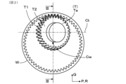
- FIG. 2 is a conceptual diagram of a workpiece and a gear skiving cutter during machining in the first embodiment, viewed from the axial direction of the workpiece.
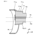
- FIG. 3 is a cross-sectional view taken along line III-III in FIG.
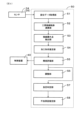
- FIG. 4 is a functional block diagram of the machining shape estimating device in the first embodiment.
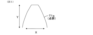
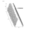
- FIG. 5 is a conceptual diagram showing a tool ridge line path on the evaluation coordinate system in the first embodiment.
- FIG. 6 is a conceptual diagram showing an evaluation tool ridgeline path on the evaluation coordinate system in the first embodiment.
- FIG. 7 is a perspective conceptual diagram of a tool ridge line path.
- FIG. 1 is a conceptual diagram showing the configuration of a gear machining apparatus provided with a machining shape estimation device according to a first embodiment.
- FIG. 2 is a conceptual diagram of a workpiece and a gear ski
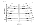
- FIG. 8 is a conceptual diagram showing the outermost points of the evaluation tool ridge line path on the evaluation coordinate system in the first embodiment.
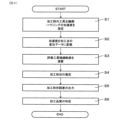
- FIG. 9 is a flow diagram of estimating the machined shape of a workpiece and determining the machining quality in the first embodiment.
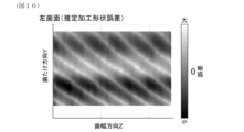
- FIG. 10 is a diagram showing a left tooth flank in an estimated machined shape of a workpiece in the first embodiment.
- FIG. 11 is a diagram showing a right tooth flank in an estimated machined shape of a workpiece in the first embodiment.
- FIG. 12 is a diagram showing a tooth profile error of the left tooth flank in the estimated machined shape of the workpiece in the first embodiment.
- FIG. 13 is a diagram showing a tooth profile error of a right tooth flank in an estimated machined shape of a workpiece in the first embodiment.
- FIG. 14 is a diagram showing a tooth trace form error of the left tooth flank in the estimated machined shape of the workpiece in the first embodiment.
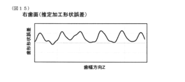
- FIG. 15 is a diagram showing a tooth trace form error of a right tooth flank in an estimated machined shape of a workpiece in the first embodiment.
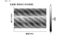
- FIG. 16 is a diagram showing a left tooth flank in a machined shape of a workpiece actually measured in the first embodiment.
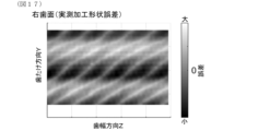
- FIG. 17 is a diagram showing a right tooth flank in a machined shape of a workpiece actually measured in the first embodiment.
- FIG. 18 is a diagram showing a tooth profile error of the left tooth flank in the machined shape of a workpiece actually measured in the first embodiment.
- FIG. 19 is a diagram showing a tooth profile error of a right tooth flank in an actually measured machined shape of a workpiece in the first embodiment.
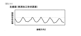
- FIG. 20 is a diagram showing the tooth trace form error of the left tooth flank in the machined shape of the workpiece actually measured in the first embodiment.
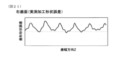
- FIG. 21 is a diagram showing the tooth trace form error of the right tooth flank in the machined shape of the workpiece actually measured in the first embodiment.
- FIG. 22 is a functional block diagram of a machining shape estimating device according to the second embodiment.
- (Embodiment 1) Configuration of the gear machining device 1
- the machining shape estimation device 50 of this embodiment estimates the machining shape of a workpiece W in a gear machining device 1 that performs tooth profile generating processing.
- a gear machining device 1 that generates a tooth profile (gear teeth) on the workpiece W using a cutting tool T by moving the tool T and the workpiece W relatively while rotating them will be described with reference to Fig. 1.
- the gear machining device 1 generates internal teeth on the inner peripheral surface of the workpiece W as an example.
- the gear machining device 1 is a general-purpose machine tool, for example, a machining center.
- the machining center is configured to allow cutting tools to be replaced, and can perform machining according to the attached tool.
- replaceable cutting tools T include gear skiving cutters and hob cutters.
- the gear machining device 1 becomes a device that processes a tooth profile (gear teeth) on the workpiece W by gear skiving.
- the gear machining device 1 becomes a device that processes a tooth profile (gear teeth) on the workpiece W by hob processing.
- the tool exchange device and the tool magazine that stores multiple tools are not shown in FIG. 1.
- the machining center serving as the gear machining device 1 is basically a horizontal machining center.
- the gear machining device 1 can also be configured in other ways, such as a vertical machining center.
- the gear machining device 1 has, for example, three mutually orthogonal linear axes (X-axis, Y-axis, Z-axis) as drive axes.
- the direction of the rotation axis of the cutting tool T is defined as the Z-axis direction
- the two axes perpendicular to the Z-axis direction are defined as the X-axis and Y-axis.
- the horizontal direction is the X-axis direction
- the vertical direction is the Y-axis direction.
- the gear machining device 1 has one rotation axis (B axis) as a drive axis for changing the relative position between the workpiece W and the cutting tool T.
- the B axis is a rotation axis with an axis line parallel to the Y axis direction as its center of rotation.
- the gear machining device 1 also has the Ct axis as a rotation axis for rotating the cutting tool T, and the Cw axis as a rotation axis for rotating the workpiece W.
- the Ct axis is a rotation axis with an axis line parallel to the Z axis direction as its center of rotation.
- the Cw axis is a rotation axis with an axis line parallel to the Z axis direction as its center of rotation when the B axis is set as the reference angle.
- the configuration for moving the workpiece W and the cutting tool T relative to one another can be selected as appropriate.
- the gear machining device 1 may be configured to have an A-axis with the X-axis direction as the center of rotation instead of the B-axis.
- the gear machining device 1 in which the cutting tool T can move linearly in the Y-axis and Z-axis directions, the workpiece W can move linearly in the X-axis direction, and the workpiece W can rotate about the B-axis.
- the gear machining device 1 comprises a bed 10, a workpiece holding device 20, a tool holding device 30, and a control device 40, which constitute the machining machine body.
- a machining shape estimation device 50 which will be described later, is connected to the gear machining device 1.
- Each element that constitutes the gear machining device 1 will be described below.
- the bed 10 is installed on an installation surface and formed into a shape that corresponds to the shape of the workpiece holding device 20 and the shape of the tool holding device 30.
- the bed 10 is, for example, rectangular.
- a pair of X-axis guide rails 11 extending in the X-axis direction and a pair of Z-axis guide rails 12 extending in the Z-axis direction are formed.
- the workpiece holding device 20 allows the workpiece W to move linearly in the X-axis direction relative to the bed 10, and to rotate about the B-axis and Cw-axis.
- the workpiece holding device 20 mainly comprises an X-axis moving table 21, a B-axis rotating table 22, and a workpiece spindle device 23.
- the X-axis moving table 21 moves in the X-axis direction while being guided by the X-axis guide rail 11 of the bed 10 by an X-axis moving device (not shown).
- the B-axis rotating table 22 is installed on the upper surface of the X-axis moving table 21 and moves in the X-axis direction together with the X-axis moving table 21.
- a rotating device 44 (described later) is connected to the B-axis rotating table 22, and the B-axis rotating table 22 can rotate on the B axis via the rotating device 44.
- the workpiece spindle device 23 is provided on the B-axis rotating table 22, and rotates about the B-axis integrally with the B-axis rotating table 22.
- the workpiece spindle device 23 holds the workpiece W rotatably.
- a rotary motor (not shown) is housed in the workpiece spindle device 23, and the workpiece spindle device 23 can rotate the workpiece W about the Cw axis by driving the rotary motor. In this way, the workpiece holding device 20 allows the workpiece W to move in the X-axis direction relative to the bed 10, and to rotate about the B axis and Cw axis.
- the workpiece spindle device 23 comprises a workpiece side housing 23a and a workpiece spindle 23b.
- the workpiece side housing 23a of the workpiece spindle device 23 is fixed to the B-axis rotating table 22, and the workpiece spindle 23b of the workpiece spindle device 23 is rotatably supported by the workpiece side housing 23a.
- a workpiece W is attached to the tip of this workpiece spindle 23b.
- the workpiece W is cantilevered by the workpiece spindle 23b of the workpiece spindle device 23.
- the tool holding device 30 mainly comprises a column 31, a saddle 32, a tool spindle device 33, and sensors 34 and 35.
- the column 31 moves in the Z-axis direction while being guided by the Z-axis guide rail 12 of the bed 10 by a Z-axis moving device 43 described below.
- a Y-axis guide rail 31a is formed on the surface of the column 31 that extends in the vertical direction (the left surface in FIG. 1).
- the saddle 32 moves in the Y-axis direction while being guided by the Y-axis guide rail 31a of the column 31 by being driven by a driving device such as a linear motor or a ball screw mechanism (not shown).
- the tool spindle device 33 is mounted on the saddle 32 and moves integrally with the saddle 32 in the Y-axis direction.
- the tool spindle device 33 holds a cutting tool T.
- a rotary motor (not shown) is housed in the tool spindle device 33, and the tool spindle device 33 is capable of rotating the cutting tool T about the Ct axis when driven by the rotary motor.
- the tool holding device 30 holds the cutting tool T so that it can move in the Y-axis and Z-axis directions relative to the bed 10 and can rotate about the Ct axis.
- the tool spindle device 33 includes a tool spindle side housing 33a and a tool spindle 33b.
- the housing of the tool spindle device 33 is fixed to the saddle 32, and the tool spindle 33b of the tool spindle device 33 is rotatably supported by the tool spindle side housing 33a.
- a cutting tool T is attached to the tip of this tool spindle 33b. In other words, the cutting tool T is cantilevered by the tool spindle 33b of the tool spindle device 33.
- the sensor 34 is provided in the tool spindle side housing 33a of the tool spindle device 33.
- the sensor 34 is an acceleration sensor and is configured to detect vibrations of the tool spindle device 33.
- the sensor 34 may be provided in the saddle 32.
- the sensor 34 measures acceleration in the tooth thickness direction X and the tooth depth direction Y, which will be described later.
- the control device 40 is equipped with an arithmetic processing device (processor) and a storage device, and controls each drive device by executing a machining program. In other words, the control device 40 controls the rotation of the cutting tool T, the rotation of the workpiece W, and the relative movement between the workpiece W and the cutting tool T. The control device 40 then controls each drive device (not shown) while synchronously controlling the rotation of the workpiece spindle device 23 and the tool spindle device 33 in order to machine gear teeth on the workpiece W.
- processor arithmetic processing device
- control device 40 sets the rotation axis Ct of the cutting tool T to a state in which it has an axis crossing angle (not shown) with respect to an axis parallel to the rotation axis Cw of the workpiece W.
- control device 40 rotates the B-axis rotating table 22 to position the workpiece W and the cutting tool T to a state in which they have an axis crossing angle.
- the control device 40 then moves the cutting tool T relative to the workpiece W in the axial direction of the workpiece W while synchronously rotating the workpiece W and the cutting tool T via a drive device (not shown), thereby creating internal teeth on the inner peripheral surface of the workpiece W.
- the gear skiving cutter Ta is a tool for generating internal teeth on the inner peripheral surface of the workpiece W.
- the gear skiving cutter Ta is attached to the tool spindle 33b (shown in Figure 1) of the tool spindle device 33 and rotates integrally with the tool spindle 33b.
- the gear skiving cutter Ta includes a plurality of cutting blades T1 and a spindle mounting part T2.
- the gear skiving cutter Ta is connected to the tool spindle 33b via the spindle mounting part T2.
- the multiple cutting edges T1 are formed on the outer peripheral surface of the gear skiving cutter Ta (corresponding to the outer peripheral surface of the cutting tool T) and are blades for machining the inner peripheral surface of the workpiece W.
- the multiple cutting edges T1 are arranged in the circumferential direction of the gear skiving cutter Ta. In this embodiment, the multiple cutting edges T1 are formed at equal intervals in the circumferential direction as an example, but they may also be formed at unequal intervals by providing chipping edges.
- the cutting edges T1 may be formed to have a positive or negative twist angle with respect to the rotation axis Ct of the gear skiving cutter Ta, or may be formed parallel (zero twist angle).
- the twist angle of the cutting edges T1 is determined by the twist angle of the internal teeth of the workpiece W and the cross-axis angle between the rotation axis Cw of the workpiece W and the rotation axis Ct of the gear skiving cutter Ta, among other machining conditions.
- Each of the multiple cutting edges T1 has a rake surface T1a at the axial end face of the gear skiving cutter Ta, a front clearance surface T1b at the outer peripheral surface of the gear skiving cutter Ta, and a side clearance surface T1c at a surface having a normal in the circumferential direction of the gear skiving cutter Ta.
- the rake surface T1a of the cutting edge T1 is formed to have a positive rake angle, but can be set to have any rake angle.
- the front clearance surface T1b of the cutting blade T1 is formed so as to be inclined with respect to the rotation axis Ct of the gear skiving cutter Ta, i.e., so as to be located on a conical surface. In other words, the front clearance surface T1b of the cutting blade T1 has a positive front clearance angle.
- the front clearance surface T1b of the cutting blade T1 may be formed so as to be parallel to the rotation axis Ct of the gear skiving cutter Ta, i.e., so as to be located on a cylindrical surface.
- the circumscribing surfaces of the multiple cutting blades T1 may be formed on a conical surface or may be formed on a cylindrical surface.
- the side clearance surface T1c of the cutting blade T1 is formed so as to be inclined with respect to the tooth trace direction of the cutting blade T1. In other words, the side clearance surface T1c of the cutting blade T1 has a positive side clearance angle.
- the side of the rake face T1a of the cutting blade T1 (left side in Figure 3) is referred to as the front, and the back side of the rake face T1a of the cutting blade T1 (right side in Figure 3) is referred to as the rear.
- gear skiving cutter Ta When the gear skiving cutter Ta is used as the cutting tool T, the gear skiving cutter Ta is used to generate internal teeth on the inner peripheral surface of the workpiece W. Gear skiving is performed by the control device 40, and the rotation axis Ct of the gear skiving cutter Ta and the rotation axis Cw of the workpiece W are set to have an axis crossing angle as shown in FIG. 2. Furthermore, the control device 40 moves the gear skiving cutter Ta relative to the workpiece W in the axial direction of the workpiece W while rotating the workpiece W and the gear skiving cutter Ta synchronously. In this way, internal teeth are generated on the inner peripheral surface of the workpiece W.
- the machining shape estimation device 50 shown in Fig. 1 estimates the machining shape of the workpiece W machined by the gear machining device 1.
- the machining shape estimation device 50 is composed of a calculation processing device and a storage device, and includes a displacement data acquisition unit 51, a tool ridge line path calculation unit 52, an ridge line outermost point extraction unit 53, a machining shape estimation unit 54, an accuracy evaluation unit 55, an adjustment unit 56, a quality determination unit 57, and a defect cause estimation unit 58, as shown in Fig. 4.
- the displacement data acquisition unit 51 acquires displacement data of the machining point of the workpiece W when the workpiece W is machined using the cutting tool T.
- the displacement data of the machining point includes displacements caused by forced vibrations and self-excited vibrations when machining the workpiece W, and displacements of synchronous and asynchronous runouts caused by the spindle rotation.
- the displacement data acquisition unit 51 acquires displacement data of the machining point of the workpiece W based on the acceleration of the tool spindle side housing 33a acquired by a sensor 35 provided on the tool spindle side housing 33a, which is a non-rotating part of the gear machining device 1. More specifically, the acceleration of the tool spindle side housing 33a acquired by the sensor 35 is converted into displacement data of the tool spindle side housing 33a by applying FFT. The displacement data of the tool spindle side housing 33a is then converted into displacement data of the machining point using a transfer function.
- the conversion of displacement data using a transfer function can be performed based on the inverse conversion function method as follows. First, the transfer function between the tool spindle side housing 33a and the machining point is measured in advance by hammering. The displacement data of the tool spindle side housing 33a is then multiplied by the transfer function to convert it into the displacement of the machining point. Note that in this embodiment, the displacement data of the machining point is obtained based on the acceleration of the tool spindle side housing 33a acquired by the sensor 34 provided on the tool spindle side housing 33a, but instead of or in addition to this, the displacement data of the machining point may be obtained based on the acceleration of the workpiece side housing 23a acquired by the sensor 35 provided on the workpiece side housing 23a.
- the tool ridgeline trajectory calculation unit 52 calculates the tool ridgeline trajectory, which is the movement trajectory of the tool ridgeline that is the end of the rake face T1a of the cutting tool T, based on the displacement data of the machining point.
- the tool ridgeline trajectory is calculated for one of the multiple tooth grooves provided in the workpiece W of the cutting tool T.
- the tool ridgeline trajectory calculation unit 52 calculates the tool ridgeline trajectory based on the displacement data of the machining point acquired at each predetermined time by the displacement data acquisition unit 51.
- the calculation of the tool ridgeline trajectory is performed in a space defined by the X-axis parallel to the tooth thickness direction of the workpiece W, the Y-axis parallel to the tooth depth direction, and the Z-axis parallel to the tooth width direction.
- the tool ridgeline trajectory can be expressed as a point cloud, as shown in FIG. 5.
- an evaluation coordinate U is set, defined by the Z-axis parallel to the tooth width direction and the Y-axis parallel to the tooth depth direction.
- the evaluation coordinate U is based on the workpiece W, with the center of the workpiece W set to 0 on the X-axis and Y-axis, and the end of the workpiece W set to 0 on the Z-axis.
- the tool ridge trajectory is set as a point cloud, and the motion of the cutting tool T is calculated for each small rotation angle of the cutting tool T, i.e., for each small movement time of the cutting tool T, and displacement data of the machining point is assigned to each point that constitutes the tool ridge.
- the sampling period of the displacement data is made to match the analysis period. If the sampling period of the displacement data and the analysis period do not match, one or both may be interpolated to make the periods match.
- the points of the tool ridgeline trajectory are converted into lattice coordinate values on the evaluation coordinate U to calculate the evaluation tool ridgeline trajectory.
- the values in the tooth depth direction Y are converted into lattice coordinate values by interpolation, and then the values in the tooth width direction Z are converted into the closest lattice coordinate values to calculate the evaluation tool ridgeline trajectory.
- the value of the tooth depth direction Y of intersection B1 between a straight line connecting points A1 and A2 on the tool ridge line trajectory and a grid line perpendicular to the tooth depth direction Y is set as the Y-axis value after interpolation of points A1 and A2 on the tool ridge line trajectory.
- the value of the tooth depth direction Y of intersection B2 between a straight line connecting points A2 and A3 on the tool ridge line trajectory and a grid line perpendicular to the tooth depth direction Y is set as the Y-axis value after interpolation of points A2 and A3 on the tool ridge line trajectory.
- the Z-axis value of grid coordinate C1 closest to intersection B1 is set as the Z-axis value after conversion of points A1 and A2 on the tool ridge line.
- the Z-axis value of grid coordinate C2 closest to intersection B2 is set as the Z-axis value after conversion of points A2 and A3 on the tool ridge line trajectory.
- a transformation is performed on the point cloud of the tool ridge line trajectory to calculate the evaluation tool ridge line trajectory, which is a point cloud including points C1 and C2.
- Figure 7 shows an example of a tool ridge line trajectory after interpolation in the tooth depth direction Y of a point cloud of multiple tool ridge line trajectories (before conversion in the tooth width direction Z).
- the tool ridge line trajectory to be evaluated is converted in the tooth width direction Z by deleting all but a point cloud whose points after interpolation in the tooth depth direction Y are located inside the workpiece W.
- the outermost edge point extraction unit 53 shown in FIG. 4 extracts the outermost point of the tool ridgeline trajectory that is located closest to the inside of the workpiece W from the tool ridgeline trajectory that has multiple X-axis values at each coordinate value of the Z-axis and Y-axis.
- the point located on the rightmost side (positive side) of the points forming the right-side ridgeline on the X-axis and Y-axis coordinate V is extracted as the outermost point CR
- the point located on the leftmost side (negative side) of the points forming the left-side ridgeline is extracted as the outermost point CL.
- the outermost point is then stored in a memory unit (not shown), and points other than the outermost point are deleted from the evaluation tool ridgeline trajectory.
- the machining shape estimation unit 54 estimates the machining shape of the workpiece W based on the outermost points of the tool ridgeline path.
- the machining shape estimation unit 54 estimates the machining shape of the workpiece W based on the outermost points CR, CL of the evaluation tool ridgeline path, assuming that the shapes CR, CL of the outermost points of the evaluation tool ridgeline path are transferred to the machining surface of the workpiece W by machining with the cutting tool T.
- the tool ridgeline path of the cutting edge of the cutting tool T that works on one tooth groove in the workpiece W is calculated, and the machining shape of one tooth groove in the workpiece W is estimated.
- the machining shape estimation unit 54 is configured to obtain an estimation result before starting machining of the workpiece to be machined next to the workpiece W whose machining shape is to be estimated.
- the estimation result by the machining shape estimation unit 54 can be expressed, for example, as a two-dimensional cross section of the machining surface or a three-dimensional shape of the machining surface.
- the accuracy evaluation unit 55 compares the machining shape of the workpiece W, which is preset as the ideal machining shape, with the machining shape estimated by the machining shape estimation unit 54 to evaluate the machining accuracy. For example, the difference between the ideal machining shape and the machining shape can be calculated as an error to evaluate the machining accuracy.
- the ideal machining shape can be specified based on the design value of the gear shape that is preset.
- the adjustment unit 56 adjusts the machine settings or machining conditions of the gear machining device 1 based on the evaluation results of the accuracy evaluation unit 55.
- the evaluation results are obtained before starting machining of the workpiece W to be machined next after the workpiece W whose machining shape is to be estimated, and adjustments are made by the adjustment unit 56, so that the machine settings or machining conditions adjusted by the adjustment unit 56 can be reflected in the machining of the next workpiece.
- the machine settings include at least one of the position data of the cutting tool T or the workpiece W in the gear machining device 1, the power values of various moving devices for moving to a specified position, the amount of runout of the tool rake face of the cutting tool T, the number of times of re-grinding, the amount of outer diameter runout, the tool specifications after re-grinding, the amount of tool wear, and the specifications related to the tool coating.
- the adjustment unit 56 adjusts the machine settings or machining conditions of the gear machining device 1 based on the evaluation results of the accuracy evaluation unit 55.
- the adjustment unit 56 may adjust the machine settings or machining conditions of the gear machining device 1 based on the estimation results of the machining shape estimation unit 54.
- the quality judgment unit 57 judges the quality of the processing of the workpiece W based on the evaluation result of the accuracy evaluation unit 55.
- the quality judgment can be such that if the error as the evaluation result of the accuracy evaluation unit 55 is equal to or less than a predetermined reference value, the processing quality is judged to be good, and if it exceeds the reference value, the processing quality is judged to be poor.
- the defect cause estimation unit 58 estimates the cause of poor machining quality for the workpiece W that has been determined to be of poor quality by the quality determination unit 57, based on the machining shape of the workpiece W estimated by the machining shape estimation unit 54. There are no limitations on the method for estimating the cause of poor machining quality, but the estimation can be made based on the results of comparing the machining shape of the workpiece W estimated by the machining shape estimation unit 54 with the ideal machining shape.
- step S1 shown in Fig. 9 when the gear cutting apparatus 1 is machining the workpiece W, the sensor 34 measures the acceleration of the tool spindle side housing 33a. Then, in step S2, the displacement data acquisition unit 51 converts the acceleration of the tool spindle side housing 33a into displacement data of the machining point of the workpiece W based on the above-mentioned inverse transfer function method.
- step S3 the tool ridgeline path calculation unit 52 calculates the above-mentioned evaluation tool ridgeline path based on the displacement data of the machining points.
- the dashed line connecting the black circles in FIG. 6 can be shown as the evaluation tool ridgeline path.
- step S4 the ridgeline outermost point extraction unit 53 extracts the outermost point of the evaluation tool ridgeline path.
- the outermost points CR and CL of the evaluation tool ridgeline path shown in FIG. 6 are extracted.
- step S4 shown in FIG. 9 the machining shape estimation unit 54 estimates the machining shape of the workpiece W
- step S5 the accuracy evaluation unit 55 calculates the machining shape error, which is the error between the machining shape of the workpiece W estimated by the machining shape estimation unit 54 and the ideal machining shape, and outputs it as shown in FIGS. 10 to 15.
- step S6 the quality determination unit 57 determines whether the machining quality of the workpiece W is good or bad. This ends the flow.
- the tool ridgeline path is calculated from the displacement data of the machining point, and the machining shape of the workpiece W is estimated based on the outermost point of the tool ridgeline path extracted from the tool ridgeline path. Since the displacement data of the machining point includes the influence of vibrations occurring at the machining point when machining is performed by the gear machining device 1, the tool ridgeline path and its outermost point calculated from the displacement data also include the influence of vibrations. As a result, the estimated machining shape of the workpiece W also includes the influence of vibrations occurring at the machining point, and the machining shape of the workpiece W can be estimated with high accuracy.
- the machining shape of the workpiece W is estimated based on the outermost point extracted from the tool ridgeline path, the amount of calculation can be suppressed from increasing compared to the case of using a voxel model or the case of using the Z map method, and therefore the machining shape of the workpiece W can be estimated with high accuracy in a short time.
- the outermost point of the tool ridge line locus is the point located most positive in the tooth thickness direction on the tool ridge line locus on the positive side of the tooth thickness direction X, and is the point located most negative in the tooth thickness direction X on the tool ridge line locus on the negative side of the tooth thickness direction.
- this embodiment includes an accuracy evaluation unit 55 that compares a preset machining shape of the workpiece W with the estimation result of the machining shape estimation unit 54 to evaluate the machining accuracy. This allows for high-precision machining accuracy in the estimated machining shape.
- this embodiment includes an adjustment unit 56 that adjusts the machine settings or processing conditions of the gear processing device 1 based on the evaluation results of the accuracy evaluation unit 55. This makes it possible to improve the processing accuracy of the workpiece W by the gear processing device 1.
- the adjustment unit 56 adjusts the machine settings or machining conditions of the gear machining device 1 based on the evaluation results of the accuracy evaluation unit 55, but instead, the adjustment unit 56 may adjust the machine settings or machining conditions of the gear machining device 1 based on the estimation results of the machining shape estimation unit 54. Even in this case, it is possible to improve the machining accuracy of the workpiece W by the gear machining device 1.
- this embodiment includes a quality judgment unit 57 that judges whether the machining quality of the workpiece W is good or bad based on the evaluation result of the accuracy evaluation unit 55, and a defect cause estimation unit 58 that estimates the cause of the poor quality based on the machining shape of the workpiece W estimated by the machining shape estimation unit 54 for the workpiece W that has been judged to be of poor quality by the quality judgment unit 57. This makes it possible to easily and accurately judge whether the machining quality of the workpiece W is good or bad.
- the machining shape estimation unit 54 obtains an estimation result before starting machining of the workpiece W that is to be machined next to the workpiece W whose machining shape is to be estimated. This makes it possible to further improve the machining quality of the next workpiece W by adjusting the machining conditions, etc. using the estimation result.
- the displacement data acquisition unit 51 acquires the acceleration of the tool spindle side housing 33a, which is the non-rotating part of the gear machining device 1, converts the acquired acceleration into displacement data of the non-rotating part, and converts the displacement data of the non-rotating part into displacement data of the machining point using a transfer function. This makes it possible to acquire with high accuracy the displacement data of the machining point, which is difficult to measure directly.
- the displacement data acquisition unit 51 acquires displacement data at each predetermined time (rotation angle of the cutting tool T), and the tool ridgeline trajectory calculation unit calculates the tool ridgeline trajectory based on the displacement data of the machining point acquired at each predetermined time, and calculates an evaluation tool ridgeline trajectory by converting the tool ridgeline trajectory into lattice coordinate values on evaluation coordinates U formed of a unit lattice including a Y axis parallel to the tooth depth direction and a Z axis parallel to the tooth width direction in the machining shape to be formed on the workpiece W. Then, the ridgeline outermost point extraction unit 53 extracts the outermost point of the evaluation tool ridgeline trajectory as the outermost point of the tool ridgeline trajectory. This makes it possible to further reduce the amount of calculation required to calculate the outermost point of the tool ridgeline trajectory, and to estimate the machining shape of the workpiece W in a shorter time.
- the tool ridge line path calculation unit 52 converts the Y-axis values in the tool ridge line path into lattice coordinate values by interpolation, and converts the Z-axis values in the tool ridge line path into the closest lattice coordinate values to calculate the evaluation tool ridge line path. This makes it suitable for calculating the evaluation tool ridge line path from the tool ridge line path that is drawn as a shape rising in the tooth depth direction Y in the evaluation coordinate U.
- the tool ridgeline path calculation unit 52 converts the Y-axis value and then converts the Z-axis value. This makes it possible to calculate the evaluation tool ridgeline path from the tool ridgeline path that is drawn as a shape rising in the tooth depth direction Y in the evaluation coordinate U.
- the non-rotating part which is the part that measures the acceleration to obtain the displacement data of the machining point
- the tool spindle side housing 33a that supports the tool spindle 33b to which the cutting tool T is attached in the gear machining device 1.
- the non-rotating part that measures the acceleration to obtain the displacement data of the machining point may be the workpiece side housing 23a that holds the workpiece spindle 23b to which the workpiece W is attached in the gear machining device 1. Even in this case, it is possible to obtain the displacement data of the machining point with high accuracy by calculating the displacement data of the machining point based on the acceleration of the workpiece side housing 23a that is located close to the machining point, without directly measuring the acceleration of the machining point.
- a vibration prediction unit 551 is provided as shown in Fig. 22.
- the vibration prediction unit 551 predicts the vibration mode during meshing of a gear pair consisting of the workpiece W having a tooth profile generated, based on the machining shape of the workpiece W estimated by the machining shape estimation unit 54. This makes it possible to predict the vibration mode without evaluating the machining accuracy of the workpiece W.
- the adjustment unit 56 and the quality determination unit 57 adjust the machining conditions and the like and determine the quality of the machining quality based on the prediction result of the vibration prediction unit 551.
- a tool runout data storage unit 59 is provided in which runout data of the cutting edge tip position due to mounting error of the cutting tool T is stored in advance, and the tool ridgeline trajectory calculation unit 52 calculates the tool ridgeline trajectory based on the displacement data of the machining point and the tool runout data.
- Runout of the cutting edge tip position due to mounting error of the cutting tool T cannot be measured by the sensor 34 (35), which is an acceleration sensor. Therefore, by measuring and storing the tool runout of the cutting tool T in advance and calculating the tool ridgeline trajectory based on the displacement data of the machining point and the stored tool runout data, it is possible to calculate the tool ridgeline trajectory with higher accuracy.
- a machining shape estimation device 50 can be provided that can estimate the machining shape of a gear machining device 1 that performs tooth profile generation processing with high accuracy and in a short time.
Landscapes
- Engineering & Computer Science (AREA)
- Human Computer Interaction (AREA)
- Manufacturing & Machinery (AREA)
- Physics & Mathematics (AREA)
- General Physics & Mathematics (AREA)
- Automation & Control Theory (AREA)
- Mechanical Engineering (AREA)
- Numerical Control (AREA)
Priority Applications (4)
| Application Number | Priority Date | Filing Date | Title |
|---|---|---|---|
| DE112023006288.9T DE112023006288T5 (de) | 2023-05-08 | 2023-05-08 | Bearbeitungsformschätzvorrichtung |
| JP2025519210A JPWO2024231990A1 (cg-RX-API-DMAC7.html) | 2023-05-08 | 2023-05-08 | |
| PCT/JP2023/017334 WO2024231990A1 (ja) | 2023-05-08 | 2023-05-08 | 加工形状推定装置 |
| CN202380097381.7A CN121038921A (zh) | 2023-05-08 | 2023-05-08 | 加工形状推断装置 |
Applications Claiming Priority (1)
| Application Number | Priority Date | Filing Date | Title |
|---|---|---|---|
| PCT/JP2023/017334 WO2024231990A1 (ja) | 2023-05-08 | 2023-05-08 | 加工形状推定装置 |
Publications (1)
| Publication Number | Publication Date |
|---|---|
| WO2024231990A1 true WO2024231990A1 (ja) | 2024-11-14 |
Family
ID=93431518
Family Applications (1)
| Application Number | Title | Priority Date | Filing Date |
|---|---|---|---|
| PCT/JP2023/017334 Ceased WO2024231990A1 (ja) | 2023-05-08 | 2023-05-08 | 加工形状推定装置 |
Country Status (4)
| Country | Link |
|---|---|
| JP (1) | JPWO2024231990A1 (cg-RX-API-DMAC7.html) |
| CN (1) | CN121038921A (cg-RX-API-DMAC7.html) |
| DE (1) | DE112023006288T5 (cg-RX-API-DMAC7.html) |
| WO (1) | WO2024231990A1 (cg-RX-API-DMAC7.html) |
Citations (3)
| Publication number | Priority date | Publication date | Assignee | Title |
|---|---|---|---|---|
| JP2014237185A (ja) * | 2013-06-07 | 2014-12-18 | 株式会社ジェイテクト | 歯車加工シミュレーション装置 |
| JP2017144502A (ja) * | 2016-02-16 | 2017-08-24 | 株式会社ジェイテクト | 歯車の歯形のシミュレーション装置及び方法並びに加工用工具の刃面のシミュレーション装置及び方法 |
| JP2023033825A (ja) * | 2021-08-30 | 2023-03-13 | 株式会社ジェイテクト | 歯車研削加工シミュレーション方法および装置 |
Family Cites Families (3)
| Publication number | Priority date | Publication date | Assignee | Title |
|---|---|---|---|---|
| JP5595146B2 (ja) | 2010-07-05 | 2014-09-24 | 株式会社ジェイテクト | 加工シミュレーション装置および最適工程決定装置 |
| JP7015041B2 (ja) | 2017-10-06 | 2022-02-02 | 国立大学法人神戸大学 | 切削シミュレーション方法および装置 |
| JP6944103B2 (ja) | 2019-10-22 | 2021-10-06 | エヌティーエンジニアリング株式会社 | 作業機械の加工状態監視方法及びシステム |
-
2023
- 2023-05-08 JP JP2025519210A patent/JPWO2024231990A1/ja active Pending
- 2023-05-08 WO PCT/JP2023/017334 patent/WO2024231990A1/ja not_active Ceased
- 2023-05-08 DE DE112023006288.9T patent/DE112023006288T5/de active Pending
- 2023-05-08 CN CN202380097381.7A patent/CN121038921A/zh active Pending
Patent Citations (3)
| Publication number | Priority date | Publication date | Assignee | Title |
|---|---|---|---|---|
| JP2014237185A (ja) * | 2013-06-07 | 2014-12-18 | 株式会社ジェイテクト | 歯車加工シミュレーション装置 |
| JP2017144502A (ja) * | 2016-02-16 | 2017-08-24 | 株式会社ジェイテクト | 歯車の歯形のシミュレーション装置及び方法並びに加工用工具の刃面のシミュレーション装置及び方法 |
| JP2023033825A (ja) * | 2021-08-30 | 2023-03-13 | 株式会社ジェイテクト | 歯車研削加工シミュレーション方法および装置 |
Also Published As
| Publication number | Publication date |
|---|---|
| DE112023006288T5 (de) | 2026-03-05 |
| JPWO2024231990A1 (cg-RX-API-DMAC7.html) | 2024-11-14 |
| CN121038921A (zh) | 2025-11-28 |
Similar Documents
| Publication | Publication Date | Title |
|---|---|---|
| US11733673B2 (en) | Numerical control system and motor drive controller | |
| JP5234772B2 (ja) | 工作機械の振動抑制方法及び装置 | |
| CN102622489B (zh) | 基于acis平台的五轴侧铣加工切削力预测方法 | |
| Artetxe et al. | Solid subtraction model for the surface topography prediction in flank milling of thin-walled integral blade rotors (IBRs) | |
| US20150160049A1 (en) | Geometric error identification method of multi-axis machine tool and multi-axis machine tool | |
| JP4433422B2 (ja) | 振動抑制装置 | |
| Torta et al. | Surface morphology prediction model for milling operations | |
| WO2012153157A2 (en) | Method for optimizing cutting forces in a milling process and computer-controlled milling machine using the same method | |
| Yu et al. | Integration of tool error identification and machining accuracy prediction into machining compensation in flank milling | |
| Sun et al. | A review on theories/methods to obtain surface topography and analysis of corresponding affecting factors in the milling process | |
| Bertok et al. | A system for monitoring the machining operation by referring to a predicted cutting torque pattern | |
| Sun et al. | Chatter stability of orthogonal turn-milling analyzed by complete discretization method | |
| JP7740152B2 (ja) | 加工条件設定方法および工作機械 | |
| CN121143199A (zh) | 一种数控机床零件加工误差补偿方法及相关设备 | |
| JP2023084538A (ja) | 工作機械における誤差推定方法、工作機械の制御装置 | |
| JP6611319B2 (ja) | 切削負荷予測方法、切削負荷予測システム、及び切削負荷予測プログラム及び記憶媒体 | |
| JP7792111B1 (ja) | 創成表面のテクスチャに基づくフライス工具の取付偏心量の計算方法 | |
| CN115204029B (zh) | 螺旋锥齿轮铣齿机床工艺可靠性评价及优化方法 | |
| CN108647413A (zh) | 一种微细表面位置误差与稳定性综合预测方法 | |
| Chu et al. | Spline-constrained tool-path planning in five-axis flank machining of ruled surfaces | |
| Chen et al. | Prediction of surface topography for the five-axis bull-nose end milling of directional plexiglass considering tool runout and dynamic displacement | |
| CN109299581A (zh) | 一种结合曲面插值的端面铣刀铣削力预测方法 | |
| CN121038921A (zh) | 加工形状推断装置 | |
| JP7829422B2 (ja) | 工作機械のびびり振動抑制方法及びびびり振動抑制システム | |
| CN113385984B (zh) | 一种刀具径向跳动识别方法、装置、终端及存储介质 |
Legal Events
| Date | Code | Title | Description |
|---|---|---|---|
| 121 | Ep: the epo has been informed by wipo that ep was designated in this application |
Ref document number: 23936544 Country of ref document: EP Kind code of ref document: A1 |
|
| WWE | Wipo information: entry into national phase |
Ref document number: 2025519210 Country of ref document: JP |
|
| WWE | Wipo information: entry into national phase |
Ref document number: 112023006288 Country of ref document: DE |
|
| WWP | Wipo information: published in national office |
Ref document number: 112023006288 Country of ref document: DE |
|
| 122 | Ep: pct application non-entry in european phase |
Ref document number: 23936544 Country of ref document: EP Kind code of ref document: A1 |