WO2024228320A1 - 撮像装置、測距方法 - Google Patents
撮像装置、測距方法 Download PDFInfo
- Publication number
- WO2024228320A1 WO2024228320A1 PCT/JP2024/014492 JP2024014492W WO2024228320A1 WO 2024228320 A1 WO2024228320 A1 WO 2024228320A1 JP 2024014492 W JP2024014492 W JP 2024014492W WO 2024228320 A1 WO2024228320 A1 WO 2024228320A1
- Authority
- WO
- WIPO (PCT)
- Prior art keywords
- irradiation
- light
- unit
- distance measurement
- view
- Prior art date
- Legal status (The legal status is an assumption and is not a legal conclusion. Google has not performed a legal analysis and makes no representation as to the accuracy of the status listed.)
- Ceased
Links
Images













Classifications
-
- G—PHYSICS
- G02—OPTICS
- G02B—OPTICAL ELEMENTS, SYSTEMS OR APPARATUS
- G02B7/00—Mountings, adjusting means, or light-tight connections, for optical elements
- G02B7/28—Systems for automatic generation of focusing signals
- G02B7/30—Systems for automatic generation of focusing signals using parallactic triangle with a base line
- G02B7/32—Systems for automatic generation of focusing signals using parallactic triangle with a base line using active means, e.g. light emitter
-
- G—PHYSICS
- G03—PHOTOGRAPHY; CINEMATOGRAPHY; ANALOGOUS TECHNIQUES USING WAVES OTHER THAN OPTICAL WAVES; ELECTROGRAPHY; HOLOGRAPHY
- G03B—APPARATUS OR ARRANGEMENTS FOR TAKING PHOTOGRAPHS OR FOR PROJECTING OR VIEWING THEM; APPARATUS OR ARRANGEMENTS EMPLOYING ANALOGOUS TECHNIQUES USING WAVES OTHER THAN OPTICAL WAVES; ACCESSORIES THEREFOR
- G03B13/00—Viewfinders; Focusing aids for cameras; Means for focusing for cameras; Autofocus systems for cameras
- G03B13/32—Means for focusing
- G03B13/34—Power focusing
- G03B13/36—Autofocus systems
-
- H—ELECTRICITY
- H04—ELECTRIC COMMUNICATION TECHNIQUE
- H04N—PICTORIAL COMMUNICATION, e.g. TELEVISION
- H04N23/00—Cameras or camera modules comprising electronic image sensors; Control thereof
- H04N23/60—Control of cameras or camera modules
-
- H—ELECTRICITY
- H04—ELECTRIC COMMUNICATION TECHNIQUE
- H04N—PICTORIAL COMMUNICATION, e.g. TELEVISION
- H04N23/00—Cameras or camera modules comprising electronic image sensors; Control thereof
- H04N23/60—Control of cameras or camera modules
- H04N23/67—Focus control based on electronic image sensor signals
Definitions
- This technology relates to an imaging device and a distance measurement method using the imaging device.
- Some imaging devices are equipped with a distance measurement module having a TOF (Time of Flight) sensor to detect distance information (depth information) to a subject.
- TOF Time of Flight
- Japanese Patent Application Laid-Open No. 2003-233693 discloses a technique relating to an imaging device equipped with a distance measuring device.
- An area ranging type refers to one in which the measuring points that can measure the distance simultaneously are distributed in two dimensions.
- the camera's imaging angle of view becomes narrower.
- the ranging module's ranging angle of view is fixed, part of the ranging data will become distance information for depths outside the camera's angle of view. If distance information is used for focus control or metadata for image depth information, there is no use for ranging data outside the camera's angle of view, so unnecessary data is being processed.
- This disclosure therefore proposes technology that makes it possible to eliminate unnecessary distance measurement processing.
- the imaging device includes a distance measuring unit having an irradiation unit with a fixed irradiation direction and a light receiving unit that receives reflected light from a subject of light irradiated from the irradiation unit, thereby determining distance information to the subject, and a control unit that performs control to change the irradiation range of light from the irradiation unit in response to a change in the imaging angle of view. That is, the irradiation range of the irradiation section in the distance measuring section is not always kept constant, but is changed according to the imaging angle of view.
- irradiation unit with a fixed irradiation direction refers to an irradiation unit whose irradiation direction is fixed during distance measurement. For example, even if the irradiation direction is adjustable, it is included in the above-mentioned irradiation unit as long as the direction is not changed during distance measurement.
- FIG. 1 is a block diagram of a configuration example of an imaging device according to a first embodiment of the present technology
- 11 is an explanatory diagram of a state in which the imaging angle of view and the illumination range for distance measurement coincide with each other.
- FIG. 11 is an explanatory diagram of a state in which the imaging angle of view and the illumination range for distance measurement do not match.
- FIG. 4 is an explanatory diagram of an irradiation spot pattern according to the embodiment.
- 5A to 5C are explanatory diagrams of distance measuring operations according to an embodiment.
- 11A and 11B are explanatory diagrams of a distance measurement operation in which a frame time is changed according to an embodiment.
- 11A and 11B are explanatory diagrams of a distance measuring operation in which the emission intensity is changed according to the embodiment.
- 11A and 11B are explanatory diagrams of distance measurement operations in which the emission intensity is changed and the frame time is kept constant according to an embodiment.
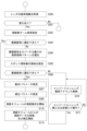
- 11 is a flowchart of an example of a control process for changing an illumination area by variably setting a spot illumination area when a lens is attached according to an embodiment.
- 11 is a flowchart of an example of a control process related to a distance measuring operation when a lens is detached according to an embodiment.
- FIG. 13 is a block diagram of a configuration example of an imaging apparatus according to a second embodiment.
- FIG. 13 is a block diagram of a configuration example in which a conversion lens is attached in the second embodiment.
- 11A and 11B are explanatory diagrams of a correction process according to a change in the optical path length.
- 11A and 11B are explanatory diagrams of a correction process according to a change in the optical path length.
- 11 is a flowchart of an example of a control process for changing an illumination area by changing a zoom magnification according to an embodiment.
- 6A and 6B are explanatory diagrams illustrating a change in the distance measurement angle of view due to a change in the zoom magnification according to the embodiment.
- 11 is a flowchart of an example of a control process for changing an illumination area by setting a zoom magnification and a spot illumination area according to an embodiment.
- 4A and 4B are diagrams illustrating the difference in zoom range between the imaging unit and the distance measurement module.
- 11A and 11B are explanatory diagrams of an operation of changing an illumination area by setting a zoom magnification and a spot illumination area according to an embodiment.
- 11 is a flowchart of an example of a control process for changing an illumination area by setting a zoom magnification and a spot illumination area according to an embodiment.
- 11A and 11B are explanatory diagrams of an operation of changing an illumination area by setting a zoom magnification and a spot illumination area according to an embodiment.
- 11 is a flowchart of an example of a process for associating metadata according to an embodiment;
- FIG. 2 is an explanatory diagram of metadata contents according to an embodiment.
- 11 is a flowchart showing a process for changing an illumination range by a conversion lens according to an embodiment.
- 11A to 11C are explanatory diagrams of parameter control in response to a change in the irradiation range according to the embodiment.
- 11A to 11C are explanatory diagrams of parameter control in response to a change in the irradiation range according to the embodiment.
- Example of the configuration of the imaging device according to the first embodiment ⁇ 2.
- Example of configuration of imaging device according to second embodiment ⁇ 4. Controlling the illumination range by changing the zoom magnification> ⁇ 5.
- image is used to include both still images and moving images.
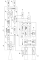
- Fig. 1 shows an example of the configuration of an imaging device 1 according to a first embodiment.
- the imaging device 1 includes an imaging section 10, a camera signal processing section 13, a recording section 14, an output section 15, a user interface section 16, a memory section 17, and a distance measurement module 20.
- the configuration in Fig. 1 is merely an example showing the main parts of the imaging device 1, and the imaging device 1 may include components not shown, and does not need to include all of the components shown.
- the imaging unit 10 includes a lens system 11 and an image sensor 12 (imaging element).
- the lens system 11 is, for example, configured as an interchangeable lens, and is detachable from the main body of the imaging device 1.
- the lens system 11 is not limited to an interchangeable lens, and may be a lens built into the main body of the imaging device 1.
- the lens system 11 includes lenses such as a zoom lens and a focus lens, an aperture mechanism, and a drive mechanism for these optical elements. Light from the subject is guided by this lens system 11 and focused on the image sensor 12.
- the figure also shows a lens position encoder 11a, which outputs information on the lens positions of the focus lens and zoom lens.
- the image sensor 12 is configured as, for example, a charge coupled device (CCD) type or a complementary metal oxide semiconductor (CMOS) type.
- the image sensor 12 performs, for example, CDS (Correlated Double Sampling) processing, AGC (Automatic Gain Control) processing, etc., on the electrical signal obtained by photoelectrically converting the received light, and further performs A/D (Analog/Digital) conversion processing, and outputs the captured image signal as digital data to the downstream camera signal processor 13.
- CDS Correlated Double Sampling
- AGC Automatic Gain Control
- A/D Analog/Digital
- the camera signal processing unit 13 is configured as an image processing processor using, for example, an LSI (Large Scale Integration).
- the camera signal processing unit 13 includes a camera control unit 30, a RAW correction signal processing unit 31, a YC development signal processing unit 32, a YC codec unit 33, a RAW codec unit , a file generation processing unit , and a lens control unit .
- the RAW correction signal processing unit 31 performs correction processing and the like on the captured image data from the image sensor 12, that is, the RAW image data.
- the YC developed signal processing unit 32 performs various necessary development processes such as color separation processing, luminance signal processing, and color matrix processing on the RAW image data.
- the YC codec section 33 performs codec for recording or transmission on the developed captured image data.
- the RAW codec unit 34 performs codec for recording and transmitting RAW image data.
- the file generation processing unit 35 performs processing for generating files required for recording or transmission on the developed captured image data or RAW image data.
- the image data to be recorded (developed captured image data or RAW image data) is transferred from the camera signal processing unit 13 to the recording unit 14. Also, the image data to be sent and output (developed captured image data or RAW image data) is transferred from the camera signal processing unit 13 to the output unit 15.
- the recording unit 14 performs a process of recording image files (content files) such as still image data and video data, attribute information of the image files, thumbnail images, and the like, on a recording medium such as a non-volatile memory.
- image files content files
- the recording unit 14 may be a circuit unit that performs recording and playback on a flash memory built into the imaging device 1, or a card recording and playback unit that performs recording and playback access on a memory card (e.g., a portable flash memory) that can be attached to and detached from the imaging device 1.
- the recording unit 14 may also be realized as a hard disk drive (HDD) or solid state drive (SSD) built into the imaging device 1.
- HDD hard disk drive
- SSD solid state drive
- the output unit 15 performs wired or wireless communication with external devices. For example, the output unit 15 transmits and outputs captured image data (still image files and video files) to an external display device, recording device, playback device, etc.
- the output unit 15 may also be a network communication unit that communicates via various networks, such as the Internet, a home network, or a LAN (Local Area Network), and transmits and receives various data between servers, terminals, etc. on the network.
- the camera control unit 30 controls the entire system within the imaging device 1 .
- the lens control unit 36 performs drive control of the lenses of the lens system 11 based on instructions from the camera control unit 30. For example, it performs drive control of a focus operation, a zoom operation, an aperture adjustment operation, etc.
- the lens system 11 includes a motor that drives the focus lens and the zoom lens, a motor that drives the aperture mechanism, and a motor drive circuit that drives these motors.
- the lens control unit 36 transmits a drive control signal to the motor drive circuit.
- the lens control unit 36 also acquires information from the lens position encoder 11 a and transmits the lens position, that is, information such as the focus position and the zoom angle of view, to the camera control unit 30 .
- the camera control unit 30 and the lens control unit 36 are shown as being built into the microprocessor that serves as the camera signal processing unit 13, but they may also be configured as a microprocessor separate from the camera signal processing unit 13.
- the memory unit 17 stores information used by the camera control unit 30 for processing. For example, this refers to a ROM (Read Only Memory), RAM (Random Access Memory), flash memory, etc.
- the memory unit 17 may be a memory area built into a microcomputer chip that constitutes the camera control unit 30, or may be configured as a separate memory chip.
- the RAM in the memory unit 17 is used as a working area for various data processing by the microprocessor functioning as the camera control unit 30, and is used for temporarily storing data, programs, and the like.
- the ROM and flash memory (non-volatile memory) in the memory unit 17 are used to store an OS (Operating System) for the camera control unit 30 to control each unit, content files such as image files, application programs for various operations, firmware, etc.
- OS Operating System
- the camera control unit 30 executes programs stored in the ROM, flash memory, or the like of the memory unit 17 to comprehensively control the entire imaging device 1 .
- the camera control unit 30 controls the operation of each necessary part regarding the control of the shutter speed of the image sensor 12, instructions for various signal processing in the camera signal processing unit 13, image capture and recording operations in response to user operations, playback operations of recorded image files, camera operations such as zoom, focus, and exposure adjustment, user interface operations, etc.
- the user interface unit 16 is configured with, for example, a display unit and controls, and displays various information to the user. It also accepts user operations and notifies the camera control unit 30 of the operation information.
- the distance measurement module 20 includes a surface emitting laser 21, an irradiation optical system 22, a light receiving optical system 23, and a distance measurement sensor unit 24, and performs distance measurement processing using the TOF method to obtain distance information.
- the distance information is the distance in the depth direction to the subject imaged by the imaging unit 10, that is, so-called depth information.
- the surface-emitting laser 21 is configured by arranging laser elements such as a vertical cavity surface-emitting laser (VCSEL) in a plane, and performs multiple spot irradiations distributed in a plane.
- VCSEL vertical cavity surface-emitting laser
- the laser elements may be arranged in a line, and multiple spot irradiations distributed in a line may be performed.
- the distance measuring module 20 in the embodiment will be described as an example of a type in which the surface emitting laser 21 performs spot irradiation, but a type in which uniform light is applied instead of forming a spot on the subject may also be used.
- the amount of light per spot can be increased and the distance measurement can be extended, but the number of distance measurement points can be limited to the number of spots.
- the number of distance measurement points can be the same as the number of pixels on the light receiving side.
- the irradiation optical system 22 is an optical system that irradiates the light from the surface-emitting laser 21 toward the subject. In the first embodiment, the irradiation angle of the irradiation optical system 22 is fixed.
- the irradiation direction of the laser light from the surface-emitting laser 21 and the irradiation optical system 22 is fixed. That is, the optical axis direction of the irradiated light is fixed, and the optical axis direction of the irradiated light is not changed by, for example, a horizontal or vertical scanning mechanism.
- the fixed irradiation direction (the direction of the optical axis of the irradiated light) is the direction of the subject imaged by the imaging unit 10. This is for the purpose of obtaining information about the distance to the subject.
- the term "fixed irradiation direction" refers to a direction that is fixed at least during distance measurement.
- the irradiation direction can be adjusted by an adjustment mechanism or the irradiation direction can be changed by attachment or detachment, as long as the direction of the optical axis of the irradiated light is not dynamically changed during distance measurement, this falls under the category of "fixed irradiation direction" in this disclosure.
- the illumination light output from the surface-emitting laser 21 through the illumination optical system 22 is reflected by the subject and becomes reflected light.
- the reflected light is then incident on the light-receiving optical system 23 and received by the light-receiving pixel array 42 in the distance measurement sensor unit 24.
- the light-receiving optical system 23 is configured as an optical system with the same fixed angle of view as the illumination optical system 22.
- the distance measurement sensor unit 24 includes a light receiving pixel array 42 , a sensor control unit 41 , a distance estimation processing unit 43 , and a timing generator 44 .
- the timing generator 44 generates a light emission timing signal for the laser element of the surface emitting laser 21 and causes the surface emitting laser 21 to perform irradiation.
- the distance estimation processing unit 43 calculates information about the distance to the subject based on the difference between the light receiving time at the light receiving pixel array 42 and the light emitting time of the surface emitting laser 21 .
- the sensor control unit 41 controls communication with the camera control unit 30 and the processing of a distance estimation processing unit 43 and a timing generator 44 as operational control of the distance measurement module 20 .
- distance measurement coordinates pixel coordinates on the light-receiving pixel array 42
- distance information for each distance measurement point are output.
- the camera control unit 30 can control the focus adjustment of the lens system 11, generate distance information for each area in the image, for example as a depth map and add it to the recorded image as metadata, or estimate the self-position of the imaging device 1 and add it to the recorded image as camera position metadata.
- the camera control unit 30 calculates the relationship between the angle of view of the lens system 11 of the attached interchangeable lens and the distance measurement angle of view of the distance measurement module 20, determines the area to be measured by the distance measurement module 20, and sends a control command to the sensor control unit 41.
- the sensor control unit 41 sets an area for spot irradiation by the surface emitting laser 21. This makes it possible to change the irradiation range even if the angle of view of the irradiation optical system 22 is fixed.
- Irradiation range control by setting spot irradiation area> The illumination range control by setting the spot illumination region, which is performed in the above-described imaging device 1, will be described below.
- the distance measuring range of the distance measuring module 20 is controlled to match the angle of view of the imaging unit 10.
- a mismatch between the imaging angle of view and the distance measurement angle of view may occur depending on the angle of view of the lens system 11 using an interchangeable lens, and this mismatch may cause unnecessary processing.
- imaging angle of view refers to an angle of view that corresponds to the range of the subject that appears in the captured image.
- This imaging angle of view mainly refers to the angle of view defined by the lens system 11 of the imaging unit 10, but the imaging angle of view may vary depending on the change in the imaging range of the image sensor 12 or the image cropping process.
- the “distance measurement angle of view” refers to the angle of view of the range where spot irradiation is performed by the distance measurement module 20, that is, the angle of view corresponding to the subject range where distance measurement is performed. If the distance measurement angle of view coincides with the imaging angle of view, distance measurement can be performed for substantially the entire area within the frame plane of the captured image, and all distance measurement data becomes valid information.
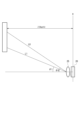
- FIG. 2 shows a schematic diagram of the relationship between the imaging angle of view (dashed line) of the lens system 11 and the distance measurement angle of view (solid line) of the projection optical system 22.
- the imaging angle of view and the distance measurement angle of view are almost the same at the focal position FP.
- FIG. 3 shows a state where an interchangeable lens, for example a telephoto lens, is attached to the lens system 11.
- an interchangeable lens for example a telephoto lens
- the imaging angle of view of the imaging unit 10 becomes narrower, but the distance measurement angle of view of the distance measurement module 20 is constant, so that a mismatch occurs between the imaging angle of view and the distance measurement angle of view at the focal position FP.
- the peripheral portion of the light receiving pixel array 42 receives reflected light from a range that is not included in the imaging angle of view, and distance measurement is performed for the background that is not included in the subject. In other words, unauthorized processing is occurring. By eliminating this unnecessary processing, it is possible to reduce processing time and increase the frame rate, thereby improving distance measurement accuracy.
- the imaging angle of view of the imaging unit 10 becomes wider, which is the opposite of FIG. 3 (not shown), and the distance measurement angle of view of the distance measurement module 20 is constant, resulting in areas in the captured image that cannot be measured.
- the distance measurement angle of view may not match the imaging angle of view of the imaging unit 10, and the distance measurement operation by the distance measurement module 20 may not be optimized. For example, optimization may not be possible in terms of processing speed, frame rate, or distance measurement range. Therefore, the distance measurement area of the distance measurement module 20 is changed according to the imaging angle of view of the imaging unit 10, thereby optimizing the distance measurement operation.
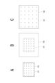
- the 4 is a schematic diagram showing the light emitting surface of the surface emitting laser 21.
- the laser elements included in the area pattern PT0 are driven to emit light in the surface emitting laser 21.
- the laser elements outside the area pattern PT0 are not driven to emit light.
- the normal state refers to a state in which the imaging angle of view and the distance measurement angle of view are substantially the same as each other, as shown in FIG.
- the laser elements included in the area pattern PT1 are driven to emit light, and the laser elements outside the area pattern PT1 are not driven to emit light.
- the light receiving pixel array 42 receives reflected light from the laser elements included in the area pattern PT1, and the distance estimation processing unit 43 performs distance measurement processing on the received light.
- the reduction in the number of irradiation spots can provide a power saving effect.
- the reduction in the number of irradiation spots can prevent an increase in the power consumption even if the number of times each spot is irradiated is increased.
- the memory load and calculation load are reduced.
- the laser elements included in the area pattern PT2 are driven to emit light.
- all the laser elements are driven to emit light. In this way, it is possible to prevent the occurrence of areas in the captured image where distance measurement is not possible.
- the irradiation range of the distance measurement module 20 can be changed according to the imaging angle of view of the lens system 11, so that distance measurement can be performed in a range that matches the imaging angle of view.
- the irradiation range is adjusted by changing the number of irradiation spots of the laser light.
- FIG. 5A shows, on the time axis, time t, and on the vertical axis, light intensity, the operation of spot irradiation for distance measurement, exposure to reflected light, and counting, on the time axis.
- spot irradiation is performed multiple times from each laser element of the surface-emitting laser 21.
- the reflected light of each spot irradiation is exposed and the time from emission to exposure is counted.
- the first to fourth spot irradiations are 10 ns, 13 ns, 11 ns, and lost. Lost refers to a state in which reflected light could not be received significantly (a state in which time could not be counted). Note that while the figure shows four spot irradiations from one laser element, this is merely a schematic diagram for explanatory purposes, and in reality, the number of spot irradiations by each laser element is usually much greater.
- 5B shows a histogram of the time from light emission to light reception obtained for one irradiation spot. Since the time is counted multiple times for each irradiation spot as described above, the histogram is generated and the peak is taken to determine accurate distance information Td for the spot irradiation.
- Such processing is performed by the distance estimation processing unit 43, but since time counting and histogram processing are performed for multiple spot irradiations for each laser element, the processing load increases as the number of laser elements (number of distance measurement points) that perform spot irradiation within a surface increases. In other words, the time required for peak detection processing is proportional to the number of distance measurement points.
- memory counters
- peak detection processing are required. The higher the count number ( ⁇ number of flashes), the higher the accuracy, but the longer the counter word length per distance measurement point.
- FIG. 6 shows an example in which the distance measurement frames are asynchronous with the frame rate of image capture on the imaging unit 10 side.
- the number of laser elements (number of distance measuring points) within the range of the area pattern PT0 is 200, and the irradiation/distance measuring angle is 20.0 degrees.
- spot irradiation is performed multiple times from each of the 200 laser elements within the range of the area pattern PT0 of the surface-emitting laser 21.
- the light-receiving pixel array 42 and distance estimation processing unit 43 during the exposure and counting period tRX, the reflected light of each spot irradiation is exposed and the time from emission to exposure is counted. Then, during the calculation and output period tPR0, distance information is calculated for each measurement point by histogram processing, and the distance information for each measurement point is output to the camera control unit 30.
- spot irradiation is performed for laser elements in a range such as area pattern PT1 in FIG. 6, in the telephoto mode, the frame time tF1 is, for example, 1/100 sec, the number of laser elements (number of distance measuring points) within the range of the area pattern PT1 is 50, and the irradiation/distance measuring angle is 9.8 degrees.
- spot irradiation is performed multiple times from each of the 50 laser elements within the range of the area pattern PT1 of the surface-emitting laser 21.
- the light-receiving pixel array 42 and distance estimation processing unit 43 during the exposure and counting period tRX, the reflected light of each spot irradiation is exposed and the time from emission to exposure is counted. Then, during the calculation and output period tPR1, distance information is calculated for each measurement point by histogram processing, and the distance information for each measurement point is output to the camera control unit 30. Since the number of distance measurement points is smaller than normal, tPR0>tPR1. This makes it possible to make the frame time tF1 shorter than the normal frame time tF0.
- the image capture device 1 When shooting telephoto, the image capture device 1 is susceptible to the effects of the movement of the image capture device 1 itself and the movement of the subject. In other words, the subject image is enlarged within the frame plane of the captured image, so even if there is the same amount of movement, the amount of movement within the image is greater than normal. In other words, the image moves quickly and there is a large variation in the subject distance for each measurement point. Therefore, it is preferable to increase the frame rate and output distance information more frequently.
- spot irradiation is performed multiple times from each of the 800 laser elements within the range of the area pattern PT2 of the surface-emitting laser 21.
- the light-receiving pixel array 42 and distance estimation processing unit 43 during the exposure and counting period tRX, the reflected light of each spot irradiation is exposed and the time from emission to exposure is counted. Then, during the calculation and output period tPR2, distance information is calculated for each measurement point by histogram processing, and the distance information for each measurement point is output to the camera control unit 30. Since there are more distance measurement points than usual, tPR0 ⁇ tPR2. As a result, the frame time tF2 is longer than the normal frame time tF0.
- the angle When the angle is wide, it is less susceptible to the movement of the imaging device 1 itself or the movement of the subject. Therefore, even if processing takes time and the frame time becomes longer, there is little impact on accuracy. Conversely, it is preferable to increase the number of ranging points so that the ranging range can be covered for the captured image.
- FIGS. 7A, 7B and 8 are schematic diagrams of the same format as those in FIGS. 5A and 5B, and therefore detailed explanation will be avoided, but they show a case in which the light intensity of spot irradiation is changed as shown by the solid and dashed lines in FIG. 7A.
- Increasing the light intensity reduces the possibility of the reflected light being lost in the light-receiving pixel array 42. This improves the accuracy of distance measurement, but increases power consumption. Taking this into consideration, distance measurement operations as shown in FIG. 8 are performed in normal, telephoto, and wide-angle modes.
- the frame time tF of the ranging frame is constant and the frame rate is not changed. This is a suitable example when you want to synchronize with the frame rate of the image capture on the imaging unit 10 side. However, it may be asynchronous with the frame rate of the image capture.
- spot irradiation is performed on the laser elements in a range such as the area pattern PT0 in FIG. 8, in normal cases, the number of laser elements (number of distance measurement points) within the range of the area pattern PT0 is 200.
- the irradiation/distance measurement angle is 20.0 degrees
- the emission intensity is P
- the number of times of emission is N.
- spot irradiation is performed N times from each of the 200 laser elements within the range of the area pattern PT0 of the surface-emitting laser 21.
- the light-receiving pixel array 42 and distance estimation processing unit 43 expose the reflected light of each spot irradiation and count the time from emission to exposure. Then, during the calculation and output period tPR0, distance information is calculated for each measurement point by histogram processing, and the distance information for each measurement point is output to the camera control unit 30.
- spot irradiation is performed for laser elements in a range such as area pattern PT1 in FIG. 8, in the telephoto mode, the number of laser elements (number of distance measuring points) within the range of the area pattern PT1 is 50.
- the irradiation/distance measuring angle is 9.8 degrees
- the emission intensity is 4 ⁇ P
- the number of times of emission is 1.5 ⁇ N.
- spot irradiation is performed 1.5 ⁇ N times from each of the 50 laser elements in the range of the area pattern PT1 of the surface-emitting laser 21.
- the reflected light of each spot irradiation is exposed in the exposure and count period tRX1, and the time from emission to exposure is counted.
- the irradiation period tTX1 and the exposure and count period tRX1 become longer than the normal irradiation period tTX0 and the exposure and count period tRX0 due to the increase in the number of times the spot irradiation is emitted.
- tPR1 distance information is calculated for each measurement point by histogram processing, and the distance information for each measurement point is output to the camera control unit 30. Since the number of distance measurement points is smaller than normal, tPR0>tPR1.
- the depth of field is shallow, so it is necessary to accurately focus on distant subjects and determine distant distances with precision. Therefore, since the illumination range is narrow, the emission intensity is increased to enable measurements over long distances. Also, by increasing the number of times the light is emitted, the precision of the distance information obtained through histogram processing is improved. At the same time, the frame time tF can be maintained.
- spot irradiation is performed for laser elements in a range such as area pattern PT2 in FIG. 8, in the case of a wide angle, the number of laser elements (number of distance measuring points) within the range of the area pattern PT2 is 800.
- the irradiation/distance measuring angle is 43.2 degrees
- the emission intensity is P
- the number of times of emission is N/4.
- the irradiation period tTX2 spot irradiation is performed N/4 times from each of the 800 laser elements in the range of the area pattern PT2 of the surface-emitting laser 21.
- the reflected light of each spot irradiation is exposed in the exposure and count period tRX2, and the time from emission to exposure is counted.
- the irradiation period tTX2 and the exposure and count period tRX2 become shorter than the normal irradiation period tTX0 and the exposure and count period tRX0 because the number of times of emission of spot irradiation is reduced.
- tPR2 distance information is calculated for each measurement point by histogram processing, and the distance information for each measurement point is output to the camera control unit 30. Since the number of distance measurement points is greater than normal, tPR0 ⁇ tPR2.
- the exposure time is reduced.
- the number of flashes is reduced. Reducing the number of flashes also reduces the counter word length required per distance measurement point. In this way, the frame time tF can be maintained and the number of distance measurement points corresponding to the wide angle can be set without increasing the hardware scale.
- distance measurement operations such as those shown in the examples of Figs. 6 and 8 above are possible.
- An example of the processing performed by the camera control unit 30 to execute such distance measurement operations is described with reference to Figs. 9 and 10.
- the camera control unit 30 issues various instruction controls to the sensor control unit 41 to execute the distance measurement operations.
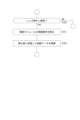
- the camera control unit 30 determines whether a lens is attached in step S101 of FIG. 9. That is, it determines whether an interchangeable lens is attached. If the camera control unit 30 determines that an interchangeable lens is attached, it proceeds to step S102.
- step S102 the camera control unit 30 determines whether or not the current mode is one in which the illumination range of the ranging module 20 is changed in accordance with the imaging angle of view.
- the modes in which the illumination range is changed in accordance with the imaging angle of view and the modes in which it is not changed will be described later.
- the camera control unit 30 performs processing to acquire information on the angle of view of the interchangeable lens in step S103.
- information on the imaging angle of view of the lens system 11 of the interchangeable lens is acquired from information from the lens position encoder 11a.
- the camera control unit 30 checks whether or not the information on the imaging angle of view has been acquired.
- the camera control unit 30 proceeds to step S105 and selects the area pattern of the smallest ranging area that covers the imaging angle of view of the lens system 11. For example, an area pattern that is suitable for the imaging angle of view of the current interchangeable lens is selected, such as area patterns PT0, PT1, and PT2 shown in FIG. 4. Note that if even the largest ranging area cannot cover the imaging angle of view, the area pattern of the largest ranging area is selected.
- step S106 the camera control unit 30 instructs the distance measurement module 20 on the execution area of spot irradiation according to the selected area pattern. That is, it instructs the laser elements inside the selected area pattern to be driven to emit light. This is an instruction for the number of distance measurement points.
- the camera control unit 30 also sets the operating parameters of the distance measurement module 20, such as the frame time (tF), the number of times each laser element emits a spot light (illumination period tTX, exposure and count period tRX), and light emission intensity.
- the camera control unit 30 starts the distance measurement operation of the distance measurement module 20 in step S110. Then, in step S111, the camera control unit 30 starts receiving distance measurement data from the distance measurement module 20, that is, information on the distance to the subject.
- the camera control unit 30 uses the received distance information for focus control, or records it as metadata in association with the captured image as a depth map of the captured image or depth information of a main subject.
- the distance measurement operation is performed in the irradiation range (distance measurement angle of view) that matches the image capture angle of view of the lens system 11 as described with reference to FIG. 6 or FIG.
- the distance measurement module 20 can adjust the irradiation range without having an optical system with a variable angle of view.
- the irradiation range of the distance measurement module 20 is narrowed and the amount of distance calculation in the distance measurement module 20 is reduced, which can be utilized to improve the distance measurement frame rate.
- the effect of reducing power consumption can be obtained by narrowing the irradiation range of the laser light emitted from the distance measurement module 20.
- the irradiation range can be widened accordingly to measure the distance to the subject in the captured image.
- the wider the angle of view the more distance measurement points there are, and the more calculations are required in the distance measurement module 20. Therefore, the increase in calculation volume can be accommodated by increasing the time available for calculation processing within the frame time.
- the camera control unit 30 sets the operating parameters of the ranging module 20 according to the mode in step S107, and starts the ranging operation of the ranging module 20 in step S110. Then, in step S111, the camera control unit 30 starts receiving distance measurement data from the distance measurement module 20, that is, information on the distance to the subject.
- step S104 If it is determined in step S104 that lens angle of view information has not been obtained, the process goes through step S107 and then to steps S110 and S111.
- illumination range control is not performed according to the imaging angle of view.
- the case where the illumination range control according to the imaging angle of view is not performed is when information on the imaging angle of view by the lens system 11 of the imaging unit 10 cannot be obtained. This is the case where the process proceeds from step S104 to step S107, and if information on the imaging angle of view cannot be obtained, it is not possible to set the illumination range of the distance measurement module 20 accordingly. In such a case, it is conceivable to measure the distance only to the center of the captured image, for example.
- the camera control unit 30 obtains information on the image capture angle of view from the information of the lens position encoder 11a, but there is other information that can be used to specify the image capture angle of view.
- imaging lens information includes focal length, image magnification, and teleconverter magnification.
- the imaging angle of view may be related not only to the angle of view of the lens system 11, but also to the imaging range and crop magnification of the image sensor 12.
- signal processing information it is preferable to include information such as distortion correction, breathing correction, camera shake correction, and recording mode (RAW/YC) in the imaging angle of view information.
- illumination range control is not performed regardless of the imaging angle of view is when the imaging device 1 is in the calibration mode. This is because when calibrating or testing the distance measuring module 20, if there are areas that are not illuminated, the task takes time and there is a possibility that the calibration will fail. If the entire area is illuminated, it is possible to detect a large deviation in the direction of irradiation and to check at once whether there are any spots with poor illumination.
- illumination range control is not performed regardless of the imaging angle of view
- the imaging device 1 is in a mode for self-position estimation or a mode for imaging for subject shape estimation (modeling).
- the imaging device 1 estimates its own position within a space in which imaging is performed, for example, it measures the distance to, for example, a wall that forms the space.
- it takes an image centered on a specific object. In these cases, even distance measurement information outside the imaging angle of view is useful for improving estimation accuracy. Therefore, it is preferable not to control the illumination range.
- the camera control unit 30 proceeds from step S102 to step S107.
- the irradiation range is controlled by selecting the laser elements emitted by the surface-emitting laser 21, that is, by selecting the area pattern.
- it is also possible to change the irradiation range by, for example, masking some of the laser elements with an aperture mechanism while emitting light from all the laser elements of the surface-emitting laser 21, or by changing the angle of view of the irradiation optical system 22.
- Possible methods for changing the angle of view of the irradiation optical system 22 include using a zoom lens, a varifocal lens, or a converter lens.
- the irradiation optical system 22 includes a zoom lens to change the angle of view of the irradiation optical system 22.
- the density of the spot irradiation will change along with the irradiation range.
- FIG. 10 shows an example of processing when the interchangeable lens is removed.
- the camera control unit 30 monitors in step S120 whether or not the interchangeable lens has been removed.
- the camera control unit 30 proceeds to step S121 and controls the distance measurement module 20 to stop the distance measurement operation. Then, in step S122, the camera control unit 30 performs a process of discarding the distance measurement data received after the distance measurement operation is stopped.
- the camera control unit 30 will perform the process in FIG. 9 again.
- the first embodiment has been described on the premise that an interchangeable lens is used, and a case has been assumed in which the angle of view on the imaging unit 10 side has changed due to lens replacement.
- the above processing can also be applied when the imaging angle of view changes due to the zoom operation of a fixed zoom lens or a variable zoom lens in the lens system 11, a change in the imaging range of the image sensor 12, or cropping control in the camera signal processing unit 13, etc.
- FIG. 11 shows an example of the configuration of an image pickup apparatus 1 according to the second embodiment.
- many parts are similar to those in Fig. 1, and the same components are denoted by the same reference numerals to avoid duplicated explanation.
- the projection optical system 22 is provided with a zoom lens 22Z
- the light receiving optical system 23 is also provided with a zoom lens 23Z.
- the irradiation optical system 22 can change the irradiation range of the spot irradiation from the surface emitting laser 21 by changing the zoom magnification of the zoom lens 22Z.
- the zoom lens 23Z of the light receiving optical system 23 is basically controlled to have the same angle of view as the zoom lens 22Z of the irradiation optical system 22, so that even if the angle of view of the irradiation optical system 22 is changed, the reflected light within the irradiation range can be received by the light receiving pixel array 42.
- the lens system 11 in the imaging unit 10 is not limited to an interchangeable lens.
- the explanation will be given mainly assuming a case where the imaging angle of view is changed by, for example, a zoom lens in the lens system 11.
- the illumination range (distance measurement angle of view) of the spot illumination by the surface-emitting laser 21 can be changed by changing the zoom magnification of the zoom lens 22Z. Therefore, by setting the zoom magnification of the zoom lens 22Z and changing the illumination range according to the information of the lens system 11 in the imaging unit 10, i.e., the imaging angle of view, the operation of the distance measurement module 20 can be optimized as described in the first embodiment.
- FIG. 12 shows a distance measurement module 20 that is equipped with an additional optical system 25, a conversion lens 18 on the light-emitting side and a conversion lens 19 on the light-receiving side.
- conversion lenses 18 and 19 can be inserted as shown in FIG. 12 to make the distance measurement angle of view equal to the image capture angle of view.
- the additional optical system 25 may be attached manually by the user, or an additional optical system 25 module may be provided that allows the conversion lenses 18, 19 to be inserted or removed from the illumination light path or the receiving light path, and the conversion lenses 18, 19 may be used under automatic control.
- optical path L0 An optical path when the angle of view is not changed by the irradiation optical system 22 is defined as optical path L0. For example, this can also be taken as the case where a conversion lens with an image magnification of 1 is used.
- the angle of optical path L0 with respect to the optical axis is defined as ⁇ 0.
- An optical path L1 is an optical path when the angle of view is narrowed, and is a case where a conversion lens with an image magnification > 1 is used.
- the angle of the optical path L1 with respect to the optical axis is ⁇ 1.
- An optical path L2 is an optical path when the angle of view is widened, and is a case where a conversion lens with an image magnification of less than 1 is used.
- the angle of the optical path L2 with respect to the optical axis is ⁇ 2.
- Optical path length L 2 ⁇ Z/cos ⁇
- Z (t, ⁇ ) Z (t, ⁇ 0) ⁇ (cos ⁇ /cos ⁇ 0)
- the above ⁇ 0, ⁇ 1, and ⁇ 2 are substituted into the term cos ⁇ .
- the depth from the reference plane R in Fig. 14 is calculated.
- the distance calculation for the light direction of ⁇ 0 is as follows. Propagation time: t0
- Propagation distance: L0 t0 x c ⁇ 2
- the calculation formula for the depth Z(t) to be used changes. Therefore, it is necessary to detect the lens status of the distance measurement module 20 and change the parameters for distance calculation according to the lens status, or perform a correction process later.
- the above description has been given in the case of the conversion lens 18, the same applies to the case where the distance measurement angle of view is changed by the zoom lens 22Z.
- FIG. 15 shows the control process of the camera control unit 30 for the distance measurement module 20. This example process is executed not only when changing the interchangeable lens, but also when changing the zoom magnification of the lens system 11, etc.
- step S102 the camera control unit 30 determines whether or not the mode is one in which the irradiation range of the distance measuring module 20 is changed in accordance with the imaging angle of view. If the mode is for changing the irradiation range of the distance measuring module 20, the camera control unit 30 performs processing for acquiring information on the angle of view of the lens system 11 in step S103. For example, information on the zoom magnification of the lens system 11 is acquired from information from the lens position encoder 11a. In step S104, the camera control unit 30 checks whether or not information on the image capture angle of view has been acquired.
- step S150 the camera control unit 30 proceeds to step S150 and sets the zoom magnification of the zoom lens 22Z so as to obtain a ranging angle of view corresponding to the imaging angle of view. Then, in step S151, the camera control unit 30 sets the operating parameters of the ranging module 20, such as the frame time, the number of times each laser element emits a spot light, and the emission intensity.
- step S152 the camera control unit 30 sets correction parameters for the distance measurement data. That is, as explained in Figures 13 and 14, the selection or correction of the formula to be applied becomes necessary depending on the change in optical path length caused by the change in zoom magnification, so the settings are made.
- the camera control unit 30 starts the distance measurement operation of the distance measurement module 20 in step S110. Then, in step S114, the camera control unit 30 starts receiving distance measurement data from the distance measurement module 20, i.e., information on the distance to the subject. In this case, the camera control unit 30 also performs a correction process on the distance measurement data in accordance with the change in the optical path length. Note that the distance measurement data corrected on the distance measurement module 20 side may be transmitted to the camera control unit 30.
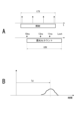
- Fig. 16A shows an imaging angle of view 100 and a ranging angle of view 101 (the irradiation range of the ranging module 20) in normal mode
- Fig. 16B in telephoto mode
- Fig. 16C in wide angle mode.
- the circles in the figures indicate the positions of spot irradiation (measurement points).
- step S102 If it is determined in step S102 that the mode does not change the irradiation range of the distance measuring module 20, or if it is determined in step S104 that the lens angle of view information has not been obtained, the camera control unit 30 sets a zoom magnification according to the mode in step S153, and performs the processes of steps S151 to S114.
- distance measurement may be performed at a normal zoom magnification, or, for example, in the above-mentioned self-position estimation mode or 3D modeling mode, distance measurement may be performed at a zoom magnification wider than the imaging angle of view.
- Irradiation range control by setting zoom magnification and spot irradiation area> For example, in the configuration of the second embodiment, the irradiation range can be changed not only by the zoom magnification of the zoom lens 22Z, but also by selecting an area pattern for spot irradiation by the surface emitting laser 21, as in the first embodiment. An example using both of these will be described with reference to Fig. 17. Fig. 17 also includes the case where the conversion lens 18 is applied.
- the processing in FIG. 17 considers a case where the range of variation of the zoom magnification of the zoom lens 22Z is narrower than the range of variation of the zoom magnification of the lens system 11.
- the lens system 11 of the imaging unit 10 can change the zoom magnification in a range of focal lengths from 20 mm to 200 mm (equivalent to a 35 mm angle of view)
- the zoom lens 22Z of the distance measurement module 20 can change the zoom magnification in a range of focal lengths from 40 mm to 80 mm (equivalent to a 35 mm angle of view).
- the camera control unit 30 performs the process of FIG. 17 repeatedly, for example, periodically.
- step S300 the camera control unit 30 performs a process of acquiring information on the angle of view of the lens system 11. For example, information on the zoom magnification of the lens system 11 is acquired from information from the lens position encoder 11a.
- step S301 the camera control unit 30 determines whether the imaging angle of view has changed since the previous acquisition, and if it has not changed, ends the process of FIG. 17 from step S301.
- step S302 the camera control unit 30 sets the zoom magnification of the zoom lens 22Z so that a distance measurement angle of view corresponding to the imaging angle of view is obtained.
- step S303 the camera control unit 30 determines whether the distance measurement angle of view is adapted to the imaging angle of view by the zoom magnification setting of the zoom lens 22Z. This is because, in the example of FIG. 18, the zoom lens 22Z may not be able to accommodate the zoom magnification of the imaging unit 10.
- the camera control unit 30 proceeds from step S303 to step S307, and sets the operating parameters of the distance measurement module 20. For example, the frame time, the number of times each laser element emits a spot light, the emission intensity, etc.
- step S308 the camera control unit 30 sets correction parameters for the distance measurement data. That is, since it becomes necessary to select or correct the calculation formula to be applied as described in Figures 13 and 14 according to the change in optical path length caused by the change in zoom magnification, the camera control unit 30 sets the correction parameters.
- the camera control unit 30 starts the distance measurement operation of the distance measurement module 20 in step S110, and starts receiving distance measurement data, i.e., information on the distance to the subject, from the distance measurement module 20 in step S114.
- Fig. 19A shows a state in which the distance measurement angle of view 101 is adapted to the imaging angle of view 100.
- the distance measurement angle of view 101 can also be adapted by changing the zoom magnification of the zoom lens 22Z. This is an example of a case in which it is determined in step S303 that the angle of view has been adapted.
- the illumination range is optimized for the captured image by adjusting the distance measurement angle of view using the zoom lens 22Z.
- FIG. 19B shows an example in which the distance measurement angle of view of the zoom lens 22Z is not adapted to the imaging angle of view 100.
- the camera control unit 30 proceeds from step S303 to step S304 and selects the area pattern of the smallest ranging area that covers the imaging angle of view of the lens system 11.
- an area pattern that is suitable for the current imaging angle of view is selected, such as the area patterns PT0, PT1, and PT2 shown in FIG. 4 as examples.
- an area pattern that corresponds to the ranging angle of view 101 in FIG. 19D is selected.
- step S305 the camera control unit 30 instructs the distance measurement module 20 on the execution area of spot irradiation according to the selected area pattern. That is, it instructs the laser elements inside the selected area pattern to be driven to emit light. This is an instruction for the number of distance measurement points.
- the laser elements at the positions indicated by circles in FIG. 19D are set to perform spot irradiation, and the laser elements indicated by black circles are set not to emit light.
- step S306 the camera control unit 30 checks whether the distance measurement angle of view 101 is adapted to the imaging angle of view 100 or not. For example, the camera control unit 30 sets an area pattern with a minimum number of ranging points as a settable area pattern, and determines whether or not the ranging angle of view is adapted to the imaging angle of view by selecting an area pattern with the minimum number of ranging points as the limit.
- the camera control unit 30 performs the processes from step S307 to step S114 in the same manner as described above.
- the irradiation range is optimized for the captured image by setting the area pattern for emitting light from the laser element in addition to adjusting the distance measurement angle of view by the zoom lens 22Z.
- step S306 it may be determined that the distance measurement angle of view is not suitable for the imaging angle of view.
- the camera control unit 30 proceeds to step S310, and, for example, issues an announcement to the user from the user interface unit 16 recommending the use of the conversion lens 18. This may cause the user to attach the additional optical system 25 of the conversion lenses 18 and 19.
- the camera control unit 30 may control the distance measurement module 20 to insert the additional optical system 25 into the optical path.
- the camera control unit 30 proceeds to step S311 or step S307, and executes the processes up to step S114. This makes it possible to use the conversion lens 18 to further adapt the imaging angle of view when the distance measurement angle of view by the zoom lens 22Z and the area pattern for emitting light from the laser element are both set and the imaging angle of view cannot be adapted.
- step S311 the process may return to step S302 and start over from setting the magnification of the zoom lens 22Z with the conversion lens 18 applied.
- the above process executes distance measurement in an illumination range (distance measurement angle of view) that matches the imaging angle of view. This makes it possible to perform distance measurement that covers the entire area of the captured image without generating invalid distance measurement points.
- FIG. 20 shows an example in which, like FIG. 17, the distance measurement angle of view is changed by the zoom lens 22Z and by setting the area pattern for emitting light from the laser element, but the order of the settings is reversed.
- the camera control unit 30 performs the process of FIG. 20 repeatedly, for example, periodically.
- step S300 the camera control unit 30 performs processing to acquire information on the angle of view of the lens system 11.
- step S301 the camera control unit 30 determines whether the image capture angle of view has changed since the previous acquisition, and if it has not changed, ends the processing of FIG. 20 from step S301.
- the camera control unit 30 selects an area pattern of the smallest ranging area that covers the imaging angle of view of the lens system 11 in step S304. Then, in step S305, the camera control unit 30 instructs the distance measurement module 20 on the execution area of spot irradiation in accordance with the selected area pattern, i.e., to drive the laser elements inside the selected area pattern to emit light.
- step S303 the camera control unit 30 checks whether the distance measurement angle of view is adapted to the imaging angle of view. For example, as shown in FIG. 21A, when the distance measurement angle of view 101 is adapted to the imaging angle of view 100, the camera control unit 30 proceeds from step S303 to step S307 and sets the operating parameters of the distance measurement module 20.
- step S308 the camera control unit 30 sets correction parameters for the distance measurement data.
- the zoom lens 22Z remains at the normal zoom magnification, and no correction is performed.
- the camera control unit 30 starts the distance measurement operation of the distance measurement module 20 in step S110, and starts receiving distance measurement data, i.e., information on the distance to the subject, from the distance measurement module 20 in step S114.
- the distance measurement angle of view is not adapted to the imaging angle of view at the stage of step S303.
- the camera control unit 30 sets the zoom magnification of the zoom lens 22Z so as to obtain a distance measurement angle of view corresponding to the imaging angle of view.
- step S306 the camera control unit 30 determines whether the distance measurement angle of view can be adapted to the imaging angle of view based on the zoom magnification setting of the zoom lens 22Z.
- the camera control unit 30 proceeds from step S306 to step S307 and onwards. In this case, in step S308, the camera control unit 30 sets correction parameters for the distance measurement data in accordance with the change in zoom magnification.
- step S306 If it is determined in step S306 that the distance measurement angle of view is not suitable for the imaging angle of view, the camera control unit 30 proceeds to step S310 and makes an announcement to the user from the user interface unit 16, for example, recommending the use of the conversion lens 18.
- the camera control unit 30 proceeds to step S311 or step S307, and executes the processes up to step S114.
- step S311 the process may return to step S304 and start over from selecting the area pattern with the conversion lens 18 applied.
- the above process executes distance measurement in an illumination range (distance measurement angle of view) that matches the imaging angle of view. This makes it possible to perform distance measurement that covers the entire area of the captured image without generating invalid distance measurement points.
- a conversion lens 18 may be applied as in the examples of FIG. 17 and FIG. 20.
- FIG. 22 shows an example in which both the zoom magnification of the zoom lens 22Z and the area pattern of the surface-emitting laser 21 to emit light are set, and if an irradiation range (distance measurement angle of view) that matches the imaging angle of view is still not obtained, that information is recorded as metadata.
- steps S300 to S308 are similar to those in FIG. 17, and therefore the description thereof will be omitted.
- the camera control unit 30 proceeds to step S320 to acquire information on the area outside the illumination range within the captured image plane.
- the camera control unit 30 sets operation parameters and correction parameters in steps S307 and S308, and starts the distance measurement operation of the distance measurement module 20 in step S110.
- step S115 the camera control unit 30 starts receiving distance measurement data from the distance measurement module 20, i.e., information on the distance to the subject, and performing correction processing in response to changes in the optical path length.
- the camera control unit 30 also starts processing metadata related to the distance measurement operation. That is, it generates the following metadata related to distance measurement, and performs processing to record it in association with the captured image or transmit it to an external device.
- Metadata is generated so that the position on the captured image and the depth Z can be determined. For example, a pair (x, y, z) is recorded for each ranging point. x, y are the coordinates within the plane of the captured image, and z is the measured depth (distance information).
- FIG. 23A shows a case where the imaging angle of view 100 and the distance measurement angle of view 101 are the same.
- the (x, y, z) values for each measurement point are used as metadata.
- the coordinate values recorded as metadata are projected, they are distributed over almost the entire image.
- the distance measurement angle of view 101 is narrower than the image capture angle of view 100.
- no distance information can be obtained for a certain subject 102.
- the (x, y, z) values for each measurement point are used as metadata, and information on the area where distance measurement has not been possible, i.e., information outside the irradiation range acquired in step S320, is also included in the metadata.
- the area where distance measurement has not been possible is indicated by the x coordinate value and the y coordinate value.
- FIG. 23C shows a case where the irradiable range is wider than the imaging angle of view of 100.
- the spots indicated by ⁇ are not irradiated. Therefore, for the spots indicated by ⁇ where distance measurement has been performed, the (x, y, z) set is associated with the captured image as metadata. The amount of metadata is reduced.
- the metadata for example, by adding information on the range of the distance measurement angle of view 101 shown by the dashed line in the figure, or information on the area where distance measurement is not possible as described above, the range where distance measurement is possible can be presented to the user when the captured image is displayed on the monitor.
- the total number of distance measuring points may also be included in the metadata.
- Information on the distance measurement angle of view may be included in the metadata. This may be a focal length value or a ratio value to the imaging angle of view.
- Irradiation range control using conversion lenses An example of controlling the irradiation range by the conversion lens will be described below. For example, this is an example of control in a configuration in which the conversion lens 18 can be applied as shown in Fig. 12. However, it is assumed here that the zoom lenses 22Z and 23Z in the irradiation optical system 22 and the light receiving optical system 23 are not provided or have a fixed angle of view.
- the lens system 11 of the imaging unit 10 is assumed to be an interchangeable lens.
- FIG. 24 shows an example of processing by the camera control unit 30.
- the camera control unit 30 determines whether a lens is attached, that is, whether an interchangeable lens is attached or not.
- step S103 If the camera control unit 30 determines that an interchangeable lens is attached, it proceeds to step S103 and performs processing to obtain information about the angle of view of the interchangeable lens.
- step S160 the camera control unit 30 selects the optical system of the conversion lenses 18 and 19 with the minimum magnification that covers the imaging angle of view of the lens system 11, and inserts it into the optical path.
- the camera control unit 30 may perform control to notify the user to attach the appropriate conversion lenses 18, 19, or may perform control to insert the appropriate conversion lenses 18, 19 into the optical path using an automatic insertion/removal mechanism.
- step S161 the camera control unit 30 sets the operating parameters of the distance measurement module 20.
- step S162 the camera control unit 30 sets correction parameters for the distance measurement data. That is, since it becomes necessary to select or correct the calculation formula to be applied as described in Figures 13 and 14 according to the change in the optical path length caused by the conversion lenses 18 and 19, the settings are made.
- the camera control unit 30 starts the distance measurement operation of the distance measurement module 20 in step S110, and starts receiving distance measurement data from the distance measurement module 20 and correcting the data in step S114.
- the conversion lenses 18 and 19 can be used to set the illumination range of the distance measuring module 20 so as to suit the imaging angle of view.
- the time constraint means that the frame rate is a constraint on the ranging time.
- Lowering the frame rate for ranging can reduce power consumption, but it is affected by the movement of objects. Or, it can increase the number of times the spot light is emitted, which can improve the accuracy of ranging.
- the effect of the movement of objects means that the accuracy of ranging decreases for moving subjects.
- the distance measurement time increases and power consumption increases, but the distance measurement accuracy improves by increasing the number of samples to be subjected to histogram processing.
- the number of samples to be processed by histograms is reduced, which reduces the accuracy of distance measurement, but it is possible to reduce power consumption.Also, since the distance measurement time is short, the frame rate can be increased, which improves the time resolution.
- Figure 26 shows the control content and the resulting effects according to the conditions and triggers for changing the operating parameters.
- the following examples are possible:
- the imaging device 1 is in a mode for capturing images of a fast-moving subject, such as a sports photography mode, the ranging frame rate of the ranging module 20 is increased.
- the exposure time is short (shutter opening is narrow) or in the shooting mode, the distance measurement frame rate of the distance measurement module 20 is increased.
- the irradiation period tTX becomes shorter, and thus the number of spot irradiations decreases.
- increasing the frame rate for ranging improves the ability to track the movement of the subject.
- the ranging frame rate of the ranging module 20 is lowered. If distance measurement is performed mainly for focus control, distance measurement will continue even during standby. However, if power consumption reduction is a priority, the distance measurement frame rate can be reduced.
- tTX The deeper the depth of field, the shorter the irradiation period (tTX). When the depth of field is deep, the focus range is wide, so the requirement for distance measurement accuracy is low. If power consumption reduction is a priority, it is effective to shorten the irradiation period and reduce the number of spot irradiations.
- the power exceeds a predetermined upper limit in the distance measuring module 20
- the number of spot irradiations and the light emission intensity are reduced so as to stay within the upper limit. It maintains a power limit, ensures compliance with laser safety standards, and prevents abnormal heating of the device.
- ⁇ Power reduction control is not performed while external power is being supplied. That is, the frame rate is not lowered, the number of times spot irradiation is performed is not reduced, and the emission intensity is not reduced, and priority is given to distance measurement performance.
- the camera control unit 30 changes the irradiation range to adapt to the imaging angle of view, as shown in Figure 26 above, it further determines the above conditions and triggers and switches the ranging frame rate control of the ranging module 20, the control of the irradiation period tTX of the surface-emitting laser 21, and the control of the light emission intensity, thereby realizing ranging operation appropriate to the situation.
- the imaging device 1 includes an irradiating unit (surface-emitting laser 21) having a fixed irradiation direction and a light-receiving unit (light-receiving pixel array 42) that receives reflected light from the subject of the light irradiated from the irradiating unit, and includes a distance measuring unit (distance measuring module 20) that obtains distance information to the subject.
- the imaging device 1 also includes a control unit (camera control unit 30) that performs control to change the irradiation range of the light from the irradiating unit in response to a change in the imaging angle of view. This allows the distance measurement operation to be optimized according to the imaging angle of view.
- narrowing the irradiation range enables distance measurement at a frame rate suitable for telephoto imaging and improvement of distance measurement accuracy suitable for telephoto imaging with a narrow depth of field.
- wide-angle imaging widening the irradiation range widens the range to be measured, allowing the distance measurement range to be appropriately covered for the angle of view.
- the imaging angle of view changes, for example, when an interchangeable lens is replaced, when the magnification is changed in the lens system 11 on the imaging unit 10 side, when the imaging range of the image sensor 12 is changed, or when the cropping range of the camera signal processing unit 13 is changed.
- the irradiation unit is configured by arranging a plurality of light-emitting elements, and the irradiation range is changed by variably setting the area in which the light-emitting elements are arranged, where the light-emitting elements are caused to perform irradiation.
- the surface-emitting laser 21, which is the irradiation unit is configured by arranging a plurality of light-emitting elements, each of which performs spot irradiation. Then, the irradiation range is changed by variably setting the area in which the light-emitting elements are arranged, where the light-emitting elements are caused to perform spot irradiation (see FIG. 4, FIG. 9, etc.).
- the illumination range can be changed by changing the light emitting area of the light emitting element that performs spot illumination. This makes it possible to change the illumination range regardless of the configuration of the optical system of the distance measurement module 20.
- the distance measurement module 20 is not limited to a type that performs spot illumination, but may be a type that irradiates the subject with uniform light.
- the distance measuring module 20 includes the irradiation optical system 22 for the light from the surface emitting laser 21, and the irradiation range is changed by changing the zoom magnification of the irradiation optical system 22 (see FIGS. 11, 15, etc.). For example, by providing a zoom lens 22Z in the distance measurement module 20, the irradiation range can be changed by driving the zoom lens 22Z, thereby optimizing the distance measurement operation.
- the irradiation range is changed by variably setting the area in which the light-emitting elements are arranged to irradiate light, and also by changing the zoom magnification in the irradiation optical system in the distance measuring module 20.
- the irradiation range is changed by variably setting the area in which the light-emitting elements are made to irradiate light in the surface-emitting laser 21, and also by changing the zoom magnification in the irradiation optical system 22 (see FIGS. 11, 17, 20, 22, etc.).
- the irradiation range (i.e., the distance measurement range) can be more flexibly adapted to changes in the imaging angle of view.
- the camera control unit 30 associates predetermined metadata with a captured image when there is an area outside the irradiation range of the laser light within the imaging angle of view (see Figs. 22 and 23). For example, when the distance measurement range is narrower than the angle of view of the captured image, there is a subject whose distance cannot be measured. In this case, a predetermined metadata is associated with the captured image so that the user can know that the subject is in such a state.
- examples of metadata associated with a captured image include data indicating a distance measurement range, data indicating distance measurement coordinates, data indicating the number of distance measurement data, and data indicating the angle of view of an illumination range.
- the data indicating the ranging range on the captured image allows the range of the subject for which ranging was possible to be specified on the captured image.
- the data indicating the ranging coordinates allows the position for which ranging was possible to be specified on the captured image.
- the data indicating the number of ranging data allows the state in which the imaging angle of view has narrowed to the telephoto side to be understood.
- the data indicating the angle of view of the irradiation range by the ranging module 20 allows the difference with the imaging angle of view to be understood.
- the camera control unit 30 performs control to execute a notification to the user when the imaging angle of view exceeds the angle of view corresponding to the change control range of the irradiation range (see Figures 17, 20, etc.). For example, if the distance measurement range cannot be optimized for the angle of view of the captured image, the user is notified so that some kind of action can be taken.
- the notification when the imaging angle of view exceeds the angle of view corresponding to the change control range of the irradiation range is a notification recommending attachment of the conversion lenses 18 and 19 as the irradiation optical system.
- the specified condition for performing calculation processing including correction is a condition in which a change in the irradiation range causes a change in the optical path length from the emission of light from the surface-emitting laser 21 to its reception by the light-receiving pixel array 42. If changing the illumination range causes the round-trip optical path length to the subject to vary compared to the normal illumination range, an error will occur in the calculated distance information. Therefore, a calculation process is performed that includes a correction to cancel the variation in optical path length. This makes it possible to maintain high-precision distance measurement.
- cases in which a change in the irradiation range causes a change in the optical path length are when the zoom magnification is changed by the zoom lens 22Z in the irradiation optical system 22, or when the conversion lens 18 is added as the irradiation optical system.
- the optical path length varies from the normal state. Therefore, when the magnification of the zoom lens is changed or the conversion lens 18 is added, a calculation process including a correction that takes into account the variation in the optical path length is performed to maintain high-precision distance measurement.
- the surface emitting laser 21 is configured by arranging a plurality of light emitting elements each performing spot irradiation, and an example has been given in which the spot irradiation density for a captured image is changed in response to a change in the irradiation range.
- the spot density for the captured image changes. This allows distance measurement of the optimal range in response to the change in the image field angle even if the range finder module 20 has a fixed field angle.
- the irradiation range is changed by changing the zoom magnification of the zoom lens 22Z in the distance measurement module 20, the spot density in the captured image does not change.
- the camera control unit 30 determines whether or not to change the irradiation range in response to a change in the imaging angle of view based on predetermined information (steps S102 and S104 in FIG. 9 and FIG. 15).
- the irradiation range of the ranging module 20 is not always changed in response to changes in the imaging angle of view, but is changed only when the change in the irradiation range is appropriate. This makes it possible to change the irradiation range of the ranging module 20 when appropriate depending on the application, state, mode, etc.
- the predetermined information includes information on the presence or absence of lens information (step S104 in FIG. 9 and FIG. 15).
- information on the lens system 11 of the imaging unit 10 such as lens magnification information
- the irradiation range of the distance measuring module 20 cannot be appropriately set, so the irradiation range is not changed, thereby avoiding unnecessary changes to the irradiation range.
- the predetermined information also includes information on the purpose of the distance information obtained by the distance measurement module 20 (step S102 in FIG. 9 and FIG. 15). For example, when the distance information is used for focus control or when it is associated with a captured image as metadata, it is preferable to change the irradiation range of the ranging module 20. On the other hand, when the distance information is used for calibration of the ranging module 20, when it is used for self-position estimation of the imaging device 1, when it is used for subject shape estimation (3D modeling), etc., it is preferable to obtain distance information in a range wider than the imaging angle of view, so it is considered not to change the irradiation range according to the imaging angle of view.
- the information on the purpose of the distance information is assumed to be shooting mode information.
- the shooting mode and the running application can determine the case in which the image is captured. Therefore, the camera control unit 30 can determine the use of the distance information based on the shooting mode and the running application, and determine whether or not to change the irradiation range of the distance measuring module 20 in response to a change in the image capturing angle of view by the image capturing unit 10, etc.
- the imaging device 1 is configured as an information processing device such as a smartphone
- the purpose of the distance information can be determined based on information about an application that is running. For example, when an application that captures an object for 3D modeling is started and an image is captured, the imaging mode can be determined as an imaging mode for object shape estimation.
- the camera control unit 30 controls the ranging frame rate of the ranging module 20, or the irradiation period of the surface-emitting laser 21, or the emission intensity of the surface-emitting laser 21 in response to a change in the irradiation range (see Figures 6, 8, 25, and 26).
- a more optimized distance measurement process may be realized by controlling the distance measurement frame rate, the irradiation period tTX, and the light emission intensity.
- the camera control unit 30 switches between the distance measurement frame rate control, the irradiation period control, and the light emission intensity control depending on a predetermined condition (see FIG. 26). Which control is appropriate varies from case to case. Therefore, predetermined condition judgments are made to determine which of these controls to perform, thereby optimizing the control.
- the predetermined conditions are exemplified as conditions related to any one of the shooting mode, exposure time, camera status (whether or not the camera is on standby for shooting), depth of field, lens focal length, subject light amount, and upper power limit (see FIG. 26). By determining which control is appropriate based on these conditions, it is possible to perform the optimal distance measurement operation depending on the state and situation at the time.
- the present technology can also be configured as follows.
- a distance measuring unit that has an irradiating unit with a fixed irradiating direction and a light receiving unit that receives light irradiated from the irradiating unit and reflected from the object, and that obtains information about a distance to the object;
- a control unit that performs control to change an illumination range of light from the illumination unit in response to a change in an imaging angle of view.
- the irradiation unit includes: A plurality of light emitting elements are arranged in an array, The imaging device according to (1) above, wherein an area in which light-emitting elements are arranged and in which light is emitted by the light-emitting elements is variably set, thereby changing the illumination range.
- the distance measuring unit includes an irradiation optical system for the light from the irradiation unit, The imaging device according to (1) above, wherein the illumination range is changed by changing a zoom magnification in the illumination optical system.
- the distance measuring unit includes an irradiation optical system for the light from the irradiation unit, the irradiation optical system being configured by arranging a plurality of light emitting elements; The illumination range is changed by variably setting an area in which the light-emitting elements are arranged so that the light-emitting elements are caused to irradiate the light, The imaging device according to (1) above, wherein the illumination range is also changed by changing a zoom magnification in the illumination optical system.
- the control unit is The imaging device according to any one of (1) to (4) above, wherein, in the case of an imaging angle of view in which an area outside the irradiation range of light from the irradiation unit exists, predetermined metadata is associated with the captured image.
- the predetermined metadata is The imaging device according to (5) above, including at least one of data indicating a distance measurement range, data indicating distance measurement coordinates, data indicating a number of distance measurement data, or data indicating an angle of view of an irradiation range of the irradiation unit.
- the control unit is The imaging device according to any one of (1) to (6) above, further comprising control for executing a notification to a user when an imaging angle of view exceeds an angle of view corresponding to a change control range of the illumination range.
- the notification is a notification recommending attachment of a conversion lens as an irradiation optical system for light from the irradiation unit.
- the imaging device (10) The imaging device according to (9) above, wherein the predetermined condition is a condition that a change in the irradiation range causes a change in an optical path length from the emission of light from the irradiation unit to the reception of the light by the light receiving unit.
- the imaging device described in (10) above may cause a change in the optical path length due to a change in the irradiation range when the zoom magnification is changed by a zoom lens in the irradiation optical system for the light from the irradiation unit, or when a conversion lens is added as the irradiation optical system for the light from the irradiation unit.
- the illumination unit is configured with an array of a plurality of light-emitting elements each of which performs spot illumination, and the spot illumination density for the captured image is changed in response to a change in the illumination range.
- the control unit is The imaging device according to any one of (1) to (12) above, further comprising: determining, based on predetermined information, whether or not to change the illumination range in response to a change in an imaging angle of view.
- the predetermined information includes information on the presence or absence of lens information.
- the predetermined information includes information on a purpose of the distance information obtained by the distance measuring unit.
- the imaging device in response to the change in the irradiation range, The imaging device according to any one of (1) to (16) above, further comprising: a ranging frame rate control of the ranging unit; a lighting period control of the lighting unit; or a light emission intensity control of the lighting unit.
- the control unit according to a predetermined condition, The imaging device according to (17) above, which switches among a distance measurement frame rate control of the distance measurement unit, a control of an irradiation period of the irradiation unit, and a control of a light emission intensity of the irradiation unit.
- the predetermined condition is a condition related to any one of a shooting mode, an exposure time, a camera status, a depth of field, a lens focal length, a subject light amount, and an upper limit of power.
- the imaging device according to (18) above.
- a distance measuring method for an imaging device including an imaging unit, an irradiating unit having a fixed irradiating direction, and a light receiving unit receiving light irradiated from the irradiating unit and reflected from the object, and for obtaining distance information to the object, A distance measuring method, comprising: controlling to change the irradiation range of light from the irradiation unit in response to a change in an imaging angle of view.
- the irradiation unit includes: A plurality of light emitting elements are arranged to emit spot light, The imaging device according to (1) above, wherein an area in which the light-emitting elements are arranged and in which the light-emitting elements are caused to perform spot irradiation is variably set, thereby changing the irradiation range.
- the distance measuring unit includes an irradiation optical system for the light from the irradiation unit, the irradiation optical system being configured by an array of a plurality of light emitting elements each performing spot irradiation;
- the illumination range is changed by variably setting an area in which the light-emitting elements are arranged so that the light-emitting elements perform spot illumination,
- Imaging device 10 Imaging unit 11 Lens system 12 Image sensor 13 Camera signal processing unit 14 Recording unit 15 Output unit 16 User interface unit 18, 19 Conversion lens 20 Distance measurement module 21 Surface emitting laser 22 Irradiation optical system 22Z Zoom lens 23 Light receiving optical system 23Z Zoom lens 24 Distance measurement sensor unit 25 Additional optical system 30 Camera control unit 41 Sensor control unit 42 Light receiving pixel array 43 Distance estimation processing unit
Landscapes
- Physics & Mathematics (AREA)
- Engineering & Computer Science (AREA)
- Multimedia (AREA)
- Signal Processing (AREA)
- General Physics & Mathematics (AREA)
- Optics & Photonics (AREA)
- Studio Devices (AREA)
Priority Applications (1)
| Application Number | Priority Date | Filing Date | Title |
|---|---|---|---|
| JP2025518116A JPWO2024228320A1 (https=) | 2023-05-01 | 2024-04-10 |
Applications Claiming Priority (2)
| Application Number | Priority Date | Filing Date | Title |
|---|---|---|---|
| JP2023-075501 | 2023-05-01 | ||
| JP2023075501 | 2023-05-01 |
Publications (1)
| Publication Number | Publication Date |
|---|---|
| WO2024228320A1 true WO2024228320A1 (ja) | 2024-11-07 |
Family
ID=93333027
Family Applications (1)
| Application Number | Title | Priority Date | Filing Date |
|---|---|---|---|
| PCT/JP2024/014492 Ceased WO2024228320A1 (ja) | 2023-05-01 | 2024-04-10 | 撮像装置、測距方法 |
Country Status (2)
| Country | Link |
|---|---|
| JP (1) | JPWO2024228320A1 (https=) |
| WO (1) | WO2024228320A1 (https=) |
Citations (6)
| Publication number | Priority date | Publication date | Assignee | Title |
|---|---|---|---|---|
| JP2006154368A (ja) * | 2004-11-30 | 2006-06-15 | Canon Inc | ストロボ撮影システム、ストロボ装置及びカメラ |
| JP2014157044A (ja) * | 2013-02-15 | 2014-08-28 | Canon Inc | 距離検出カメラ |
| JP2021026236A (ja) * | 2019-07-31 | 2021-02-22 | キヤノン株式会社 | 距離検出装置および撮像装置 |
| WO2021171695A1 (ja) * | 2020-02-28 | 2021-09-02 | 富士フイルム株式会社 | 撮像システム、撮像システムの制御方法、及びプログラム |
| KR20210141092A (ko) * | 2020-05-15 | 2021-11-23 | 엘지이노텍 주식회사 | 표면발광 레이저소자, 카메라 모듈 및 이미터 어레이의 배열방법 |
| JP2023047714A (ja) * | 2021-09-27 | 2023-04-06 | 株式会社Jvcケンウッド | 撮像装置、撮像方法及びプログラム |
-
2024
- 2024-04-10 WO PCT/JP2024/014492 patent/WO2024228320A1/ja not_active Ceased
- 2024-04-10 JP JP2025518116A patent/JPWO2024228320A1/ja active Pending
Patent Citations (6)
| Publication number | Priority date | Publication date | Assignee | Title |
|---|---|---|---|---|
| JP2006154368A (ja) * | 2004-11-30 | 2006-06-15 | Canon Inc | ストロボ撮影システム、ストロボ装置及びカメラ |
| JP2014157044A (ja) * | 2013-02-15 | 2014-08-28 | Canon Inc | 距離検出カメラ |
| JP2021026236A (ja) * | 2019-07-31 | 2021-02-22 | キヤノン株式会社 | 距離検出装置および撮像装置 |
| WO2021171695A1 (ja) * | 2020-02-28 | 2021-09-02 | 富士フイルム株式会社 | 撮像システム、撮像システムの制御方法、及びプログラム |
| KR20210141092A (ko) * | 2020-05-15 | 2021-11-23 | 엘지이노텍 주식회사 | 표면발광 레이저소자, 카메라 모듈 및 이미터 어레이의 배열방법 |
| JP2023047714A (ja) * | 2021-09-27 | 2023-04-06 | 株式会社Jvcケンウッド | 撮像装置、撮像方法及びプログラム |
Also Published As
| Publication number | Publication date |
|---|---|
| JPWO2024228320A1 (https=) | 2024-11-07 |
Similar Documents
| Publication | Publication Date | Title |
|---|---|---|
| US7751701B2 (en) | Imaging device performing focus adjustment based on human face information | |
| JP5653035B2 (ja) | 撮像装置、焦点検出方法、および制御方法 | |
| US7405762B2 (en) | Camera having AF function | |
| EP2464102A2 (en) | Imaging apparatus and shutter operation correcting method | |
| JP3937678B2 (ja) | 電子スチルカメラ | |
| US8059183B2 (en) | Image sensing apparatus and method for controlling the same | |
| US20160077406A1 (en) | Imaging system, lighting device, and control method | |
| JP2014202875A (ja) | 被写体追跡装置 | |
| JP2002296494A (ja) | 結像位置検出プログラムおよびカメラ | |
| JP2001141982A (ja) | 電子カメラの自動焦点調節装置 | |
| US11790600B2 (en) | Image processing device, imaging apparatus, image processing method, and recording medium | |
| US12022208B2 (en) | Imaging apparatus with multiple frame recording and control shooting period | |
| WO2024228320A1 (ja) | 撮像装置、測距方法 | |
| JP2006072384A (ja) | 自動焦点調節装置及び方法 | |
| JP4649836B2 (ja) | カメラシステム | |
| JP5023750B2 (ja) | 測距装置および撮像装置 | |
| JP2001141984A (ja) | 電子カメラの自動焦点調節装置 | |
| JP4329694B2 (ja) | 撮像装置 | |
| JP2009014495A (ja) | 計測装置及びこれを用いた計測方法 | |
| JP2001141983A (ja) | 電子カメラの自動焦点調節装置 | |
| KR101505441B1 (ko) | 촬상 장치 | |
| JP4865275B2 (ja) | 焦点検出装置及び撮像装置 | |
| JP5406659B2 (ja) | 撮像装置及びその制御方法 | |
| US20230328392A1 (en) | Imaging apparatus, imaging control method and storage medium | |
| JP2013113967A (ja) | 撮像装置及びその制御方法、並びにプログラム |
Legal Events
| Date | Code | Title | Description |
|---|---|---|---|
| 121 | Ep: the epo has been informed by wipo that ep was designated in this application |
Ref document number: 24800051 Country of ref document: EP Kind code of ref document: A1 |
|
| ENP | Entry into the national phase |
Ref document number: 2025518116 Country of ref document: JP Kind code of ref document: A |
|
| WWE | Wipo information: entry into national phase |
Ref document number: 2025518116 Country of ref document: JP |
|
| NENP | Non-entry into the national phase |
Ref country code: DE |