WO2024228285A1 - ワイヤハーネス、検知システム、および、検知方法 - Google Patents
ワイヤハーネス、検知システム、および、検知方法 Download PDFInfo
- Publication number
- WO2024228285A1 WO2024228285A1 PCT/JP2024/004750 JP2024004750W WO2024228285A1 WO 2024228285 A1 WO2024228285 A1 WO 2024228285A1 JP 2024004750 W JP2024004750 W JP 2024004750W WO 2024228285 A1 WO2024228285 A1 WO 2024228285A1
- Authority
- WO
- WIPO (PCT)
- Prior art keywords
- wire
- detection
- communication
- impedance
- conductor
- Prior art date
- Legal status (The legal status is an assumption and is not a legal conclusion. Google has not performed a legal analysis and makes no representation as to the accuracy of the status listed.)
- Ceased
Links
Images


Classifications
-
- G—PHYSICS
- G01—MEASURING; TESTING
- G01R—MEASURING ELECTRIC VARIABLES; MEASURING MAGNETIC VARIABLES
- G01R31/00—Arrangements for testing electric properties; Arrangements for locating electric faults; Arrangements for electrical testing characterised by what is being tested not provided for elsewhere
-
- H—ELECTRICITY
- H01—ELECTRIC ELEMENTS
- H01B—CABLES; CONDUCTORS; INSULATORS; SELECTION OF MATERIALS FOR THEIR CONDUCTIVE, INSULATING OR DIELECTRIC PROPERTIES
- H01B7/00—Insulated conductors or cables characterised by their form
Definitions
- This disclosure relates to a wire harness, a detection system, and a detection method.
- This disclosure claims priority to Japanese Application No. 2023-075921, filed May 2, 2023, and incorporates all of the contents of said Japanese application by reference.
- Vehicles are equipped with various on-board devices.
- the on-board devices include various ECUs (Electronic Control Units) that manage functions necessary for the vehicle, such as steering and braking. These ECUs are connected to each other to form a network. Each ECU communicates with each other via this network to realize the basic functions of the vehicle, such as "running,” “turning,” and “stopping.” Wire harnesses are usually used for communication between on-board devices.
- ECUs Electronic Control Units
- Wire harnesses are usually used for communication between on-board devices.
- Patent Document 1 proposes technology to prevent unauthorized access to in-vehicle connectors.
- Patent Document 1 relates to a security structure for a connector.
- This security structure includes a protective cover that is attached so as to cover the connector in a mated state.
- the protective cover can only be released using a special tool.
- This protective cover makes it impossible to easily remove the wire harness connected to the connector of the vehicle-mounted device. Therefore, the security structure described in Patent Document 1 can prevent unauthorized access to the vehicle-mounted device by replacing the connector or wire harness, as well as by probing the communication lines, etc.
- a wire harness is a wire harness that connects communication between a first communication unit and a second communication unit, and includes a first connector, a second connector, and a cable arranged between the first connector and the second connector.
- the cable includes a plurality of electric wires including a detection electric wire, and a conductor that functions as a ground for the detection electric wire.
- the detection electric wire is an electric wire that does not have a shield, and is arranged so that the impedance of the detection electric wire is a predetermined value.
- the present disclosure can be realized not only as a wire harness, a detection system, or a detection method including such a characteristic configuration, but also as a program for causing a computer to execute the characteristic steps executed by the detection system or the detection method, or a recording medium having the program recorded thereon. Furthermore, it can also be realized as another system or device including a wire harness or a detection system.
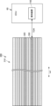
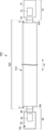
- FIG. 1 is a diagram illustrating an example of a configuration of a communication system according to a first embodiment.
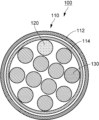
- FIG. 2 is a schematic cross-sectional view taken along line AA of the wire harness shown in FIG.
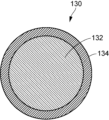
- FIG. 3 is a cross-sectional view showing an example of the configuration of the detection wire shown in FIG.
- FIG. 4 is a cross-sectional view showing an example of the configuration of the electric wire to be protected shown in FIG.
- FIG. 5 is a block diagram for explaining an example of the configuration of the in-vehicle device shown in FIG.
- FIG. 6 is a block diagram showing an example of the functional configuration of a detection device mounted on an in-vehicle device.
- FIG. 7 is a diagram for explaining the communication system shown in FIG. FIG.
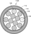
- FIG. 8 is a cross-sectional view showing a configuration example of a wire harness according to a modified example.
- FIG. 9 is a cross-sectional view showing an example of a configuration of a wire harness according to the second embodiment.
- FIG. 10 is a cross-sectional view showing an example of the configuration of the electric wire to be protected shown in FIG.
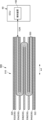
- FIG. 11 is a diagram illustrating an example of a configuration of a communication system according to the third embodiment.
- FIG. 12 is a schematic cross-sectional view taken along line BB of the wire harness shown in FIG.
- FIG. 13 is a diagram for explaining the communication system shown in FIG. 11, and is a schematic plan view of the cable portion of the wire harness in which the upper layer portion of the detection wire is omitted.
- FIG. 14 is a diagram illustrating an example of a configuration of a communication system according to the fourth embodiment.
- FIG. 15 is a schematic cross-sectional view taken along line CC of the wire harness shown in FIG.
- FIG. 16 is a diagram illustrating an example of a configuration of a communication system according to the fifth embodiment.
- FIG. 17 is a diagram for explaining the communication system shown in FIG. 16, and the diagram of the cable portion of the wire harness is a diagram that roughly shows a cross section taken along line DD of the wire harness shown in FIG. 16.
- Patent Document 1 which includes a protective cover
- Patent Document 1 which includes a protective cover
- This disclosure has been made to solve these problems, and one objective of this disclosure is to provide a wire harness, a detection system, and a detection method that can improve communication security with a configuration that is not obvious from the outside.
- a wire harness is a wire harness that connects communication between a first communication unit and a second communication unit.
- the wire harness includes a first connector, a second connector, and a cable arranged between the first connector and the second connector.
- the cable includes a plurality of electric wires including a detection electric wire, and a conductor that functions as a ground for the detection electric wire.
- the detection electric wire is an electric wire that does not have a shield, and is arranged so that the impedance of the detection electric wire is a predetermined value.
- the conductor may be stripped during probing for the purpose of stealing information, such as unauthorized access. Because the conductor functions as a ground for the detection wire, when the conductor is stripped, the impedance of the detection wire changes. By detecting this change in impedance, probing of the wire harness can be detected. This improves communication security. Because communication security can be improved without using components such as protective covers that are easily visible from the outside, it is difficult to tell from the outside whether security measures have been taken.
- the multiple electric wires may be configured to include a communication electric wire that is different from the detection electric wire.
- the detection electric wire By providing the detection electric wire separately from the communication electric wire, it is easy to arrange the detection electric wire so that its impedance becomes a predetermined value. This makes it easy to improve communication security.
- the communication wire may be configured to have a shield. This can suppress deterioration of communication performance.
- the impedance of the detection wire may be configured differently from the impedance of the communication wire. This increases the degree of freedom in setting the impedance of the detection wire, making it easier to improve communication security.
- the multiple electric wires may include communication electric wires, and the communication electric wires may include detection electric wires.
- the communication electric wires may also serve as detection electric wires. This eliminates the need to provide separate detection electric wires, thereby reducing the number of cables. Therefore, even when improving communication security, it is possible to suppress increases in the cost of the wire harness.
- the cable may be flat. This allows the positional relationship between the conductor functioning as ground and the detection wire to be easily fixed, making the impedance of the detection wire more stable. This makes it easier to detect changes in impedance, improving the accuracy of detecting unauthorized access.
- the conductor may include a sheet-shaped conductor. This makes it easier to change the impedance of the detection wire during probing, thereby further improving the accuracy of detecting unauthorized access.
- the sheet-like conductor may include a first conductor sheet and a second conductor sheet, and the detection wire may be arranged between the first conductor sheet and the second conductor sheet. In this way, when probing the flat cable from either the top or bottom side, the sheet-like conductor is peeled off, so that the impedance change of the detection wire can be effectively detected. This can further improve communication security.
- the detection electric wire when a specific electric wire among the multiple electric wires is the electric wire to be protected, the detection electric wire may be configured to be arranged in the same layer as the layer in which the electric wire to be protected is arranged. This makes it possible to more reliably change the impedance of the detection electric wire during probing, thereby further improving communication security.
- the cable may have a laminated structure in which a plurality of electric wires are arranged in a plurality of layers, and the detection electric wire may be arranged in the outermost layer of the laminated structure.
- the outermost layer in the laminated structure is the first to have its sheet peeled off during probing. Therefore, by arranging the detection electric wire in this layer, it is possible to easily detect signs of unauthorized access. Furthermore, by configuring in this way, wiring constraints on other electric wires can be reduced. For example, when a specific electric wire included in the plurality of electric wires is set as the electric wire to be protected, the electric wire to be protected can be arranged in a layer different from the detection electric wire.
- the cable may have a laminated structure in which multiple electric wires are arranged in multiple layers, and the detection electric wire may be arranged across the layers. This makes it easy to configure the detection electric wire so that its impedance changes during probing. Therefore, this configuration can further improve communication security.
- a detection system includes a wire harness and a detection device electrically connected to the wire harness.
- the wire harness includes a first connector, a second connector, and a cable arranged between the first connector and the second connector.
- the cable includes a plurality of electric wires including a detection electric wire, and a conductor that functions as a ground for the detection electric wire.
- the detection electric wire is an electric wire that does not have a shield, and is arranged so that the impedance of the detection electric wire is a predetermined value.
- the detection device includes a measurement unit that measures the impedance of the detection electric wire, and a determination unit that determines whether or not unauthorized communication is taking place based on the impedance measurement result by the measurement unit.
- the impedance of the detection wire changes.
- the measurement unit of the detection device measures the impedance of the detection wire.
- the determination unit determines whether unauthorized communication is being performed through probing, etc., based on the impedance measurement results. This improves communication security. Since communication security can be improved without using components such as protective covers that are easily visible from the outside, it is difficult to tell from the outside whether security measures have been taken.
- the determination unit may be configured to determine that unauthorized communication is occurring in response to a change in the impedance of the detection wire that is equal to or greater than a predetermined threshold value. This makes it easy to determine whether unauthorized communication is occurring through probing or the like.
- a detection method is a detection method for detecting unauthorized communication in communication via a wire harness.
- the cable of the wire harness includes a plurality of electric wires including a detection electric wire, and a conductor that functions as a ground for the detection electric wire.
- the detection electric wire is an electric wire that does not have a shield, and is arranged so that the impedance of the detection electric wire is a predetermined value.
- This detection method measures the impedance of the detection electric wire, and determines whether unauthorized communication is taking place based on the measurement result. In this way, in addition to improving communication security, it is possible to make it difficult to tell from the outside whether security measures have been taken.
- the detection method may be configured to determine that unauthorized communication is occurring in response to a change in the impedance of the detection wire that is equal to or greater than a predetermined threshold value. This makes it easy to determine whether unauthorized communication is occurring through probing or the like.
- a wire harness 100 is a wire harness used for communication between on-vehicle devices.
- the on-vehicle devices include a first on-vehicle device 60 and a second on-vehicle device 70.
- the first on-vehicle device 60 includes a first communication unit 62
- the second on-vehicle device 70 includes a second communication unit 72.
- the wire harness 100 connects the communication between the first communication unit 62 and the second communication unit 72.
- the wire harness 100 is directly connected to the first in-vehicle device 60 and the second in-vehicle device 70.
- the wire harness 100 may be configured to be indirectly connected to the first in-vehicle device 60 or the second in-vehicle device 70 via another wire harness or the like.
- the first in-vehicle device 60 and the second in-vehicle device 70 are both ECUs.
- the first communication unit 62 and the second communication unit 72 include a PHY (PHYsical layer).
- the PHY is composed of a chip (integrated circuit) mounted on the ECU that transmits and receives signals.
- the first in-vehicle device 60 includes a board 64 on which the first communication unit 62 is mounted, and a connector 66.
- the connector 66 and the first communication unit 62 are electrically connected by a wiring unit (not shown).
- the second in-vehicle device 70 includes a board 74 on which the second communication unit 72 is mounted, and a connector 76.
- the connector 76 and the second communication unit 72 are electrically connected by a wiring unit (not shown).
- the wire harness 100 includes a first connector 102, a second connector 104, and a cable 110 arranged between the first connector 102 and the second connector 104.
- the first connector 102 is connected to a first end of the cable 110
- the second connector 104 is connected to a second end of the cable 110.
- the first connector 102 is connected to a connector 66 of the first in-vehicle device 60
- the second connector 104 is connected to a connector 76 of the second in-vehicle device 70.
- the cable 110 of the wire harness 100 has a configuration in which multiple electric wires are bundled together by an insulating exterior material 112.
- the exterior material 112 is, for example, an insulating coating, and covers the multiple electric wires.
- the multiple electric wires may include electric wires that transmit highly confidential information. Since such electric wires need to be protected against unauthorized access, they may be referred to as "electric wires to be protected" below.
- a specific electric wire included in the multiple electric wires is referred to as an electric wire 120 to be protected.
- a conductor 114 that functions electrically as a ground is inserted inside the exterior material 112.
- the conductor 114 is made of a conductive material such as a metal material, and covers multiple electric wires.
- the exterior material 112 covers the multiple electric wires via the conductor 114.
- the multiple electric wires include a detection electric wire 130.
- the detection electric wire 130 is an electric wire that does not have a shield.
- the conductor 114 functions as a ground for the detection electric wire 130.
- the detection electric wire 130 is arranged (designed) so that its impedance (characteristic impedance) is a predetermined value (hereinafter sometimes referred to as a "prescribed value") by adjusting the positional relationship between the detection electric wire 130 and the conductor 114 and the material of the member arranged between the detection electric wire 130 and the conductor 114.
- the predetermined value can be, for example, 50 ⁇ 10 ⁇ .
- the predetermined value is not limited to this and may be a value other than this value.
- the detection wire 130 includes a conductive core wire 132 and an insulating coating 134 that covers the core wire 132.
- the impedance of the detection wire 130 may be adjusted by adjusting the thickness of the insulating coating 134 (thickness of the coating material) or by changing the material of the insulating coating 134.
- the electric wire 120 to be protected is an electric wire having a shield.
- the electric wire 120 to be protected includes a core wire 122, a dielectric 124 covering the core wire 122, a metal shield 126 arranged on the outside of the dielectric 124, and an insulating coating 128 covering the metal shield 126.
- the impedance (characteristic impedance) of the electric wire 120 to be protected is, for example, 50 ⁇ .
- the other electric wires except for the detection wire 130 have the same configuration as the electric wire 120 to be protected.
- the multiple electric wires including the electric wire 120 to be protected may be electric wires without a shield.
- the communication system 50 includes the wire harness 100 described above and a detection device 150 electrically connected to the wire harness 100.
- the detection device 150 detects that probing or the like is being performed by monitoring a change in impedance of the detection wire 130.
- the first vehicle-mounted device 60 includes the detection device 150. That is, the first vehicle-mounted device 60 also functions as the detection device 150.
- the detection device 150 may be configured to be included in the second vehicle-mounted device 70, or may be configured to be included in both the first vehicle-mounted device 60 and the second vehicle-mounted device 70.
- the detection device 150 may be mounted on an in-vehicle device that holds highly confidential information.
- the first in-vehicle device 60 further includes a control unit 80 and a storage unit 82 in addition to the first communication unit 62.
- the control unit 80 includes a computing element (processor) such as a CPU (Central Processing Unit) or an MPU (Micro Processing Unit).
- the storage unit 82 includes a non-volatile memory such as a flash memory.
- the storage unit 82 stores software (computer programs) executed by the control unit 80 and various information (data).
- the functions of each functional unit of the first in-vehicle device 60 are realized by software processing executed by the control unit 80 using hardware.
- the first in-vehicle device 60 also has a function as a detection device 150. Some or all of these functions may be realized by an integrated circuit including a microcomputer.
- the detection device 150 includes, as functional units, an impedance monitoring unit 152 that monitors changes in the impedance of the detection wire 130 (see FIG. 2), and a communication restriction unit 158 that restricts communication via the wire harness 100 depending on the monitoring results of the impedance monitoring unit 152.
- the impedance monitoring unit 152 includes a measurement unit 154 that measures the impedance of the detection wire 130, and a determination unit 156 that determines whether or not unauthorized communication is occurring based on the impedance measurement results by the measurement unit 154.
- the determination unit 156 determines that unauthorized communication is occurring in response to a change in the impedance of the detection wire 130 that is equal to or greater than a predetermined threshold value.
- the predetermined threshold value is set in advance and stored in the memory unit 82 (see FIG. 5).
- the determination unit 156 makes a determination by appropriately referring to the threshold value stored in the memory unit 82.
- the communication restriction unit 158 restricts communication when it is determined that unauthorized communication is occurring. Specifically, the communication restriction unit 158 blocks communication when it is determined that unauthorized communication is occurring. However, instead of blocking all communication, some communication may be allowed to continue. For example, communication of low confidentiality information via wires other than the protected wire 120 may be allowed to continue.
- TDR Time Domain Reflectometry
- the detection device 150 may use the impedance measurement function using a TDR to monitor changes in the impedance of the detection wire 130.
- the second vehicle-mounted device 70 may have a configuration similar to that of the first vehicle-mounted device 60. However, the second vehicle-mounted device 70 may be configured to include a detection device, or may not include a detection device.
- the detection device 150 of the first in-vehicle device 60 is electrically connected to the detection wire 130.
- the measurement unit 154 of the detection device 150 measures the characteristic impedance of the detection wire 130 by, for example, the TDR method.
- the outer casing 112 and the conductor 114 are stripped off. Since the conductor 114 functions as a ground for the detection wire 130, when the conductor 114 is stripped off, the impedance of the detection wire 130 changes. More specifically, when the outer casing 112 and the conductor 114 of the cable 110 are partially stripped off for probing, the impedance of the detection wire 130 in the stripped part significantly deviates from the specified value. If the impedance of the detection wire 130 deviates by more than the threshold value, there is a possibility that probing is about to be performed. When the impedance monitoring unit 152 of the detection device 150 (see FIG. 6) detects such a change in impedance, it determines that unauthorized communication is occurring. When the detection device 150 determines that unauthorized communication is occurring, it restricts the communication.
- the wire harness 100 or communication system 50 can detect signs of unauthorized access, such as probing, in advance, improving communication security.
- communication security can be improved without using components such as protective covers that are easily noticeable from the outside, making it difficult to tell from the outside whether security measures have been taken or not.
- the multiple electric wires included in the cable 110 include a communication electric wire (the electric wire 120 to be protected) that is different from the detection electric wire 130.
- a communication electric wire the electric wire 120 to be protected
- the detection wire 130 may be arranged (designed) so that the impedance of the detection wire 130 becomes a specified value by inserting another dielectric between the detection wire 130 and the conductor 114.
- An example of such a configuration will be described below.
- a dielectric 116 is disposed between the conductor 114 and the detection wire 130.
- the dielectric 116 is, for example, an insulating coating having a predetermined thickness, and covers a plurality of wires including the detection wire 130 and the wire 120 to be protected.
- the conductor 114 is disposed between the exterior material 112 and the dielectric 116. By adjusting the thickness or material of the dielectric 116, the impedance of the detection wire 130 is set to a specified value.
- the dielectric inserted between the detection wire 130 and the conductor 114 may be a dielectric other than the insulating coating.
- the dielectric may be configured to be partially inserted between the detection wire 130 and the conductor 114.
- the wire harness 200 according to the present embodiment is different from the first embodiment in that the electric wire 220 to be protected also serves as the electric wire for detection. Therefore, the electric wire 220 to be protected is an electric wire without a shield.
- the conductor 114 functions as a ground for the electric wire 220 to be protected, which also serves as the electric wire for detection. Since the electric wire 220 to be protected is also the electric wire for detection, the electric wire 220 is arranged (designed) so that its impedance (characteristic impedance) is a predetermined value (prescribed value) by adjusting the positional relationship between the conductor 114 and the material of the member arranged between the conductor 114 and the electric wire for detection.
- the predetermined value can be, for example, 50 ⁇ 10 ⁇ , as described above.
- the wire to be protected (detection wire) 220 includes a conductive core wire 222 and an insulating coating 224 that covers the core wire 222.
- This configuration eliminates the need to provide a separate detection wire, which reduces the amount of cable used. As a result, even when improving communication security, it is possible to prevent increases in the cost of wire harnesses.
- a communication system 50A according to the present embodiment differs from the first and second embodiments in that a wire harness 300 is included instead of wire harness 100 (see FIG. 1).
- the wire harness 300 includes a first connector 302, a second connector 304, and a cable 310 arranged between the first connector 302 and the second connector 304.
- the first connector 302 is connected to a first end of the cable 310
- the second connector 304 is connected to a second end of the cable 310.
- the cable 310 is a flat cable. When the cable 310 is extended in a straight line, the extension direction of the cable 310 is the L2 direction.
- the cable 310 of the wire harness 300 has a laminated structure in which multiple electric wires are arranged in multiple layers.
- FIG. 12 shows an example of a laminated structure with four layers. However, the number of layers in the laminated structure is not limited to four, and may be two, three, or five or more layers.
- the multiple electric wires include an electric wire 320 to be protected and a detection electric wire 330.
- the electric wire 320 to be protected has a similar configuration to the electric wire 120 to be protected shown in the first embodiment (see FIG. 4).
- the detection electric wire 330 is an electric wire that does not have a shield, and has a similar configuration to the detection electric wire 130 shown in the first embodiment (see FIG. 3).
- the multiple electric wires are held by a sheet-like holding member.
- the holding member includes a first sheet 340, a second sheet 342, and a third sheet 344, which are all flexible insulating sheets.
- the first sheet 340, the second sheet 342, and the third sheet 344 are formed to be, for example, the same size.
- the holding member further includes a sheet-like conductor 350.
- the sheet-like conductor 350 includes a first conductor sheet 352 and a second conductor sheet 354.
- the first conductor sheet 352 and the second conductor sheet 354 are formed to be, for example, the same size as the first sheet 340, the second sheet 342, and the third sheet 344.
- the first sheet 340 and the third sheet 344 function as an exterior material.
- each layer is sandwiched between two sheet-like holding members and fixed to the holding members arranged above and below.
- Each electric wire can be fixed to the holding member by, for example, ultrasonic welding or laser welding, or by using an adhesive.
- the detection wire 330 is arranged on the same layer as the wire 320 to be protected.
- the detection wire 330 and the wire 320 to be protected are sandwiched between the first conductor sheet 352 and the second conductor sheet 354. That is, the detection wire 330 and the wire 320 to be protected are arranged between the first conductor sheet 352 and the second conductor sheet 354. More specifically, the detection wire 330 is fixed to the first conductor sheet 352 and the second conductor sheet 354.
- the characteristic impedance of the detection wire 330 is adjusted to a predetermined value (prescribed value) by appropriately changing the thickness or material of the dielectric arranged between the first conductor sheet 352 and the second conductor sheet 354, as in the first embodiment.
- the detection device 150 of the first in-vehicle device 60 is electrically connected to the detection wire 330.
- the measurement unit 154 of the detection device 150 measures the characteristic impedance of the detection wire 330 by, for example, the TDR method.
- the sheets are peeled off first. Since the wire 320 to be protected is arranged on the same layer as the detection wire 330, when probing from the top side of the cable 310, the first sheet 340, the second sheet 342 and the first conductor sheet 352 are peeled off. On the other hand, when probing from the bottom side of the cable 310, the third sheet 344 and the second conductor sheet 354 are peeled off. In either case, the sheet-like conductor 350 is peeled off along with the exterior material.
- the impedance of the detection wire 330 changes. If the impedance of the detection wire 330 deviates by more than the threshold value, it is possible that probing is being attempted, and so when the impedance monitoring unit 152 (see FIG. 6) of the detection device 150 detects such a change in impedance, it determines that unauthorized communication is occurring. When the detection device 150 determines that unauthorized communication is occurring, it restricts the communication.
- Flat wire harnesses have the advantage that they can have a variety of functions, such as sound deadening, sound absorption, abrasion resistance, heat dissipation, shielding, and waterproofing, depending on the function of the exterior material (retaining material).
- functions such as sound deadening, sound absorption, abrasion resistance, heat dissipation, shielding, and waterproofing, depending on the function of the exterior material (retaining material).
- exterior material retaining material
- sheet-like exterior materials are easily peeled off, making it easy to peel off the sheet for probing.
- the wire harness 300 according to this embodiment and the communication system 50A equipped with the wire harness 300 can detect signs of unauthorized access, such as probing, in advance, and therefore can prevent unauthorized access through probing while enjoying the advantages of conventional wire harnesses.
- the flat cable 310 can easily fix the positional relationship between the conductor 350 that functions as the ground and the detection wire 330, making the impedance of the detection wire 330 more stable. This makes it easier to detect changes in impedance, improving the accuracy of detecting unauthorized access.
- the sheet-like conductor 350 as the conductor, it is necessary to peel off the sheet-like conductor 350 in order to expose the electric wire 320 to be protected during probing. In this way, by configuring the conductor 350 to be peeled off inevitably during probing, it is possible to easily change the impedance of the detection electric wire 330. This can further improve the accuracy of detecting unauthorized access.
- the sheet-like conductor 350 is peeled off when the flat cable 310 is probed from either the top or bottom side. This allows the impedance change of the detection wire 330 to be effectively detected, further improving communication security.
- a communication system 50B according to the present embodiment differs from the third embodiment in that a communication system 50B according to the present embodiment includes a wire harness 400 instead of the wire harness 300 (see FIG. 11).
- the wire harness 400 includes a cable 410 instead of the cable 310 (see FIG. 11).
- the cable 410 of the wire harness 400 is a flat cable, similar to the third embodiment, and has a laminated structure in which a plurality of electric wires are arranged in a plurality of layers.
- the plurality of electric wires includes the electric wire 320 to be protected and the detection electric wire 330.
- the plurality of electric wires are held by a sheet-like holding member.
- the holding member includes a first sheet 420, a second sheet 422, a third sheet 424, and a fourth sheet 426, all of which are flexible insulating sheets.
- the first sheet 420 and the fourth sheet 426 function as exterior materials.
- the holding member further includes a sheet-like conductor 350.
- the sheet-like conductor 350 includes a first conductor sheet 352 and a second conductor sheet 354.
- the detection wire 330 is arranged in the outermost layer of the laminated structure.
- the arrangement of the electric wire 320 to be protected is arbitrary.
- the electric wire 320 to be protected is arranged in a different layer from the detection wire 330.
- the electric wire 320 to be protected may be configured to be arranged in the same layer as the detection wire 330.
- the detection wire 330 is arranged between the first conductor sheet 352 and the second conductor sheet 354.
- the sheets are peeled off first. At that time, the sheets are peeled off starting from the outermost sheet up to the layer in which the electric wire 320 to be protected is arranged. Therefore, by arranging the detection electric wire 330 on the outermost layer, the conductor 350 (352) of the layer in which the detection electric wire 330 is arranged is peeled off first. This makes it easier to detect signs of unauthorized access, such as probing.
- probing can be detected without placing the electric wire 320 to be protected in the same layer as the detection electric wire 330, which reduces wiring constraints on other electric wires including the electric wire 320 to be protected. Therefore, for example, the electric wire 320 to be protected can be placed in a different layer from the detection electric wire 330.
- a flexible insulating sheet may be used instead of the second conductor sheet 354.
- a sheet-like conductor may be used instead of the second sheet 422.
- a sheet-like conductor may be used instead of the third sheet 424.
- a communication system 50C according to the present embodiment differs from the third embodiment in that a communication system 50C according to the present embodiment includes a wire harness 500 instead of the wire harness 300 (see FIG. 11).
- the wire harness 500 includes a cable 510 instead of the cable 310 (see FIG. 11).
- the cable 510 of the wire harness 500 is a flat cable, similar to the third embodiment, and has a laminated structure in which multiple electric wires are arranged in multiple layers.
- the multiple electric wires include an electric wire to be protected and an electric wire for detection.
- the multiple electric wires are held by a sheet-like holding member.
- the holding member includes a first sheet 520 and a second sheet 522, both of which are flexible insulating sheets.
- the first sheet 520 and the second sheet 522 function as exterior materials.
- the holding member further includes a sheet-like conductor 530.
- the sheet-like conductor 530 includes a first conductor sheet 532, a second conductor sheet 534, a third conductor sheet 536, a fourth conductor sheet 538, and a fifth conductor sheet 540.
- the second conductor sheet 534, the third conductor sheet 536, and the fourth conductor sheet 538 are formed with through holes through which the detection wire 550 is inserted.
- the detection wire 550 is an electric wire without a shield, and has a configuration similar to that of the detection wire 130 (see FIG. 3) shown in the first embodiment.
- the detection wire 550 is arranged across layers via through holes formed in the second conductor sheet 534, the third conductor sheet 536, and the fourth conductor sheet 538. As a result, the detection wire 550 is arranged on multiple layers, so that the impedance of the detection wire 550 changes when the conductor of any layer in the laminated structure is peeled off. This makes it easy to configure the detection wire 550 so that its impedance changes during probing. Therefore, with this configuration, communication security can be further improved.
- the wire harness may include a plurality of detection electric wires.
- a plurality of detection devices may be provided corresponding to the plurality of detection electric wires.
- the characteristic impedance of the detection wire is set to be approximately the same as that of the wire to be protected.
- the characteristic impedance of the detection wire may be set to a value (prescribed value) different from the characteristic impedance of other wires, such as the wire to be protected.
- the characteristic impedance of the other wires is 50 ⁇
- the characteristic impedance of the detection wire may be set to, for example, approximately 35 ⁇ to 40 ⁇ . This allows for greater freedom in setting the impedance of the detection wire, making it easier to improve communication security.
- an example has been shown in which it is determined that unauthorized communication is occurring when the characteristic impedance of the detection wire changes by more than a predetermined threshold value.
- the present disclosure is not limited to such an embodiment. For example, it may be determined that unauthorized communication is occurring when the difference between the characteristic impedance of the detection wire and the characteristic impedance of another wire having a shield becomes greater than a predetermined value. Furthermore, it may be determined that unauthorized communication is occurring when the range of fluctuation from the history of the characteristic impedance of the detection wire becomes greater than a predetermined value.
- the characteristic impedance of the detection wire is measured using the TDR method.
- the present disclosure is not limited to such an embodiment.
- the characteristic impedance of the detection wire may be measured using a method other than the TDR method.
- the wires in the wire harness other than the detection wire are configured to have a shield.
- the wires other than the detection wire may be configured to have a shield or may not have a shield.
- the flat wire harness has a laminated structure in which multiple layers are stacked.
- the flat wire harness may also have a single-layer structure with only one layer.
- the conductive sheet may be provided only on one side of the detection wire.
Landscapes
- Physics & Mathematics (AREA)
- General Physics & Mathematics (AREA)
- Insulated Conductors (AREA)
Priority Applications (2)
| Application Number | Priority Date | Filing Date | Title |
|---|---|---|---|
| CN202480025692.7A CN121002384A (zh) | 2023-05-02 | 2024-02-13 | 线束、检测系统以及检测方法 |
| JP2025518100A JPWO2024228285A1 (https=) | 2023-05-02 | 2024-02-13 |
Applications Claiming Priority (2)
| Application Number | Priority Date | Filing Date | Title |
|---|---|---|---|
| JP2023075921 | 2023-05-02 | ||
| JP2023-075921 | 2023-05-02 |
Publications (1)
| Publication Number | Publication Date |
|---|---|
| WO2024228285A1 true WO2024228285A1 (ja) | 2024-11-07 |
Family
ID=93332976
Family Applications (1)
| Application Number | Title | Priority Date | Filing Date |
|---|---|---|---|
| PCT/JP2024/004750 Ceased WO2024228285A1 (ja) | 2023-05-02 | 2024-02-13 | ワイヤハーネス、検知システム、および、検知方法 |
Country Status (3)
| Country | Link |
|---|---|
| JP (1) | JPWO2024228285A1 (https=) |
| CN (1) | CN121002384A (https=) |
| WO (1) | WO2024228285A1 (https=) |
Citations (8)
| Publication number | Priority date | Publication date | Assignee | Title |
|---|---|---|---|---|
| JPH09229988A (ja) * | 1996-02-21 | 1997-09-05 | Furukawa Electric Co Ltd:The | 自動車用ワイヤーハーネスシステム異常検出装置 |
| JP2000046890A (ja) * | 1998-07-30 | 2000-02-18 | Yazaki Corp | 異常検知センサ付きワイヤーハーネス、ワイヤーハーネス用異常検知センサ及びワイヤーハーネスの異常検出装置 |
| JP2000155874A (ja) * | 1998-11-18 | 2000-06-06 | Yazaki Corp | 車両用盗難防止装置 |
| JP2009269527A (ja) * | 2008-05-09 | 2009-11-19 | Toyota Motor Corp | 車両用不正操作検知装置 |
| WO2017209298A1 (ja) * | 2016-06-02 | 2017-12-07 | 住友電気工業株式会社 | 車両用の多芯フラットケーブル |
| JP2021162449A (ja) * | 2020-03-31 | 2021-10-11 | 株式会社オートネットワーク技術研究所 | 電線検査システム、電線検査方法、および電線 |
| JP2021170553A (ja) * | 2018-04-27 | 2021-10-28 | 住友電気工業株式会社 | シールドフラットケーブル |
| JP2022179553A (ja) * | 2020-11-20 | 2022-12-02 | 株式会社オートネットワーク技術研究所 | 異常予兆検知機能付ケーブルおよび電線異常予兆検知装置 |
-
2024
- 2024-02-13 JP JP2025518100A patent/JPWO2024228285A1/ja active Pending
- 2024-02-13 CN CN202480025692.7A patent/CN121002384A/zh active Pending
- 2024-02-13 WO PCT/JP2024/004750 patent/WO2024228285A1/ja not_active Ceased
Patent Citations (8)
| Publication number | Priority date | Publication date | Assignee | Title |
|---|---|---|---|---|
| JPH09229988A (ja) * | 1996-02-21 | 1997-09-05 | Furukawa Electric Co Ltd:The | 自動車用ワイヤーハーネスシステム異常検出装置 |
| JP2000046890A (ja) * | 1998-07-30 | 2000-02-18 | Yazaki Corp | 異常検知センサ付きワイヤーハーネス、ワイヤーハーネス用異常検知センサ及びワイヤーハーネスの異常検出装置 |
| JP2000155874A (ja) * | 1998-11-18 | 2000-06-06 | Yazaki Corp | 車両用盗難防止装置 |
| JP2009269527A (ja) * | 2008-05-09 | 2009-11-19 | Toyota Motor Corp | 車両用不正操作検知装置 |
| WO2017209298A1 (ja) * | 2016-06-02 | 2017-12-07 | 住友電気工業株式会社 | 車両用の多芯フラットケーブル |
| JP2021170553A (ja) * | 2018-04-27 | 2021-10-28 | 住友電気工業株式会社 | シールドフラットケーブル |
| JP2021162449A (ja) * | 2020-03-31 | 2021-10-11 | 株式会社オートネットワーク技術研究所 | 電線検査システム、電線検査方法、および電線 |
| JP2022179553A (ja) * | 2020-11-20 | 2022-12-02 | 株式会社オートネットワーク技術研究所 | 異常予兆検知機能付ケーブルおよび電線異常予兆検知装置 |
Also Published As
| Publication number | Publication date |
|---|---|
| JPWO2024228285A1 (https=) | 2024-11-07 |
| CN121002384A (zh) | 2025-11-21 |
Similar Documents
| Publication | Publication Date | Title |
|---|---|---|
| US6929900B2 (en) | Tamper-responding encapsulated enclosure having flexible protective mesh structure | |
| US11083082B2 (en) | Enclosure-to-board interface with tamper-detect circuit(s) | |
| US20130283386A1 (en) | Tamper respondent covering | |
| US9147089B2 (en) | Flexible printed cable and information processing device | |
| US20100327856A1 (en) | Security Device | |
| US20100024046A1 (en) | Methods and systems for detecting a lateral intrusion of a secure electronic component enclosure | |
| US20200125522A1 (en) | Secure crypto module including electrical shorting security layers | |
| US8259455B2 (en) | Device for protecting the pins of an electronic component | |
| JP7559812B2 (ja) | 電線異常予兆検知装置 | |
| JP7673818B2 (ja) | 電線検査システム、電線検査方法、および電線の使用方法 | |
| WO2024228285A1 (ja) | ワイヤハーネス、検知システム、および、検知方法 | |
| JPWO2012070150A1 (ja) | 電気コネクタ、列車情報送受信システム、および電気コネクタの接続方法 | |
| WO2024228247A1 (ja) | ワイヤハーネス、ハーネス識別システム、および、車載装置 | |
| US20100208436A1 (en) | Multilayer Circuit Board and Use of a Multilayer Circuit Board | |
| US9632275B2 (en) | Secure jacket | |
| JP4716199B2 (ja) | 耐タンパリング構造 | |
| WO2024228286A1 (ja) | ワイヤハーネス、ハーネスシステム、不正接続防止システム、および、車載装置 | |
| CN1193609C (zh) | 限制传送来自主设备中所形成端口的电磁辐射的端口盖 | |
| US11945381B2 (en) | In-vehicle system | |
| WO2008042679A1 (en) | Insulation barrier for unshielded wire | |
| JP2012058768A (ja) | 情報処理装置 | |
| US20060253899A1 (en) | Expansion connector | |
| KR200478773Y1 (ko) | 금융 단말기의 물리적 탐침 방지를 위한 장치의 카드 정보 리드 및 전송 디바이스 | |
| JP2023082180A (ja) | 電線検査システムおよび電線検査方法 | |
| JP2014503912A (ja) | 保護装置 |
Legal Events
| Date | Code | Title | Description |
|---|---|---|---|
| 121 | Ep: the epo has been informed by wipo that ep was designated in this application |
Ref document number: 24800016 Country of ref document: EP Kind code of ref document: A1 |
|
| ENP | Entry into the national phase |
Ref document number: 2025518100 Country of ref document: JP Kind code of ref document: A |
|
| WWE | Wipo information: entry into national phase |
Ref document number: 2025518100 Country of ref document: JP |
|
| NENP | Non-entry into the national phase |
Ref country code: DE |