WO2024225327A1 - ブランク、構造部材の製造方法、及び構造部材 - Google Patents
ブランク、構造部材の製造方法、及び構造部材 Download PDFInfo
- Publication number
- WO2024225327A1 WO2024225327A1 PCT/JP2024/016110 JP2024016110W WO2024225327A1 WO 2024225327 A1 WO2024225327 A1 WO 2024225327A1 JP 2024016110 W JP2024016110 W JP 2024016110W WO 2024225327 A1 WO2024225327 A1 WO 2024225327A1
- Authority
- WO
- WIPO (PCT)
- Prior art keywords
- steel
- blank
- steel plate
- structural member
- plate
- Prior art date
- Legal status (The legal status is an assumption and is not a legal conclusion. Google has not performed a legal analysis and makes no representation as to the accuracy of the status listed.)
- Ceased
Links
Images


Classifications
-
- C—CHEMISTRY; METALLURGY
- C21—METALLURGY OF IRON
- C21D—MODIFYING THE PHYSICAL STRUCTURE OF FERROUS METALS; GENERAL DEVICES FOR HEAT TREATMENT OF FERROUS OR NON-FERROUS METALS OR ALLOYS; MAKING METAL MALLEABLE, e.g. BY DECARBURISATION OR TEMPERING
- C21D1/00—General methods or devices for heat treatment, e.g. annealing, hardening, quenching or tempering
- C21D1/68—Temporary coatings or embedding materials applied before or during heat treatment
- C21D1/70—Temporary coatings or embedding materials applied before or during heat treatment while heating or quenching
-
- B—PERFORMING OPERATIONS; TRANSPORTING
- B21—MECHANICAL METAL-WORKING WITHOUT ESSENTIALLY REMOVING MATERIAL; PUNCHING METAL
- B21D—WORKING OR PROCESSING OF SHEET METAL OR METAL TUBES, RODS OR PROFILES WITHOUT ESSENTIALLY REMOVING MATERIAL; PUNCHING METAL
- B21D22/00—Shaping without cutting, by stamping, spinning, or deep-drawing
- B21D22/20—Deep-drawing
- B21D22/208—Deep-drawing by heating the blank or deep-drawing associated with heat treatment
-
- B—PERFORMING OPERATIONS; TRANSPORTING
- B21—MECHANICAL METAL-WORKING WITHOUT ESSENTIALLY REMOVING MATERIAL; PUNCHING METAL
- B21D—WORKING OR PROCESSING OF SHEET METAL OR METAL TUBES, RODS OR PROFILES WITHOUT ESSENTIALLY REMOVING MATERIAL; PUNCHING METAL
- B21D35/00—Combined processes according to or processes combined with methods covered by groups B21D1/00 - B21D31/00
- B21D35/002—Processes combined with methods covered by groups B21D1/00 - B21D31/00
- B21D35/005—Processes combined with methods covered by groups B21D1/00 - B21D31/00 characterized by the material of the blank or the workpiece
- B21D35/006—Blanks having varying thickness, e.g. tailored blanks
-
- B—PERFORMING OPERATIONS; TRANSPORTING
- B62—LAND VEHICLES FOR TRAVELLING OTHERWISE THAN ON RAILS
- B62D—MOTOR VEHICLES; TRAILERS
- B62D25/00—Superstructure or monocoque structure sub-units; Parts or details thereof not otherwise provided for
- B62D25/02—Side panels
-
- B—PERFORMING OPERATIONS; TRANSPORTING
- B62—LAND VEHICLES FOR TRAVELLING OTHERWISE THAN ON RAILS
- B62D—MOTOR VEHICLES; TRAILERS
- B62D25/00—Superstructure or monocoque structure sub-units; Parts or details thereof not otherwise provided for
- B62D25/04—Door pillars ; windshield pillars
-
- C—CHEMISTRY; METALLURGY
- C09—DYES; PAINTS; POLISHES; NATURAL RESINS; ADHESIVES; COMPOSITIONS NOT OTHERWISE PROVIDED FOR; APPLICATIONS OF MATERIALS NOT OTHERWISE PROVIDED FOR
- C09D—COATING COMPOSITIONS, e.g. PAINTS, VARNISHES OR LACQUERS; FILLING PASTES; CHEMICAL PAINT OR INK REMOVERS; INKS; CORRECTING FLUIDS; WOODSTAINS; PASTES OR SOLIDS FOR COLOURING OR PRINTING; USE OF MATERIALS THEREFOR
- C09D7/00—Features of coating compositions, not provided for in group C09D5/00; Processes for incorporating ingredients in coating compositions
- C09D7/40—Additives
- C09D7/60—Additives non-macromolecular
- C09D7/61—Additives non-macromolecular inorganic
-
- C—CHEMISTRY; METALLURGY
- C21—METALLURGY OF IRON
- C21D—MODIFYING THE PHYSICAL STRUCTURE OF FERROUS METALS; GENERAL DEVICES FOR HEAT TREATMENT OF FERROUS OR NON-FERROUS METALS OR ALLOYS; MAKING METAL MALLEABLE, e.g. BY DECARBURISATION OR TEMPERING
- C21D8/00—Modifying the physical properties of ferrous metals or ferrous alloys by deformation combined with, or followed by, heat treatment
-
- C—CHEMISTRY; METALLURGY
- C21—METALLURGY OF IRON
- C21D—MODIFYING THE PHYSICAL STRUCTURE OF FERROUS METALS; GENERAL DEVICES FOR HEAT TREATMENT OF FERROUS OR NON-FERROUS METALS OR ALLOYS; MAKING METAL MALLEABLE, e.g. BY DECARBURISATION OR TEMPERING
- C21D9/00—Heat treatment, e.g. annealing, hardening, quenching or tempering, adapted for particular articles; Furnaces therefor
- C21D9/0068—Heat treatment, e.g. annealing, hardening, quenching or tempering, adapted for particular articles; Furnaces therefor for particular articles not mentioned below
-
- C—CHEMISTRY; METALLURGY
- C23—COATING METALLIC MATERIAL; COATING MATERIAL WITH METALLIC MATERIAL; CHEMICAL SURFACE TREATMENT; DIFFUSION TREATMENT OF METALLIC MATERIAL; COATING BY VACUUM EVAPORATION, BY SPUTTERING, BY ION IMPLANTATION OR BY CHEMICAL VAPOUR DEPOSITION, IN GENERAL; INHIBITING CORROSION OF METALLIC MATERIAL OR INCRUSTATION IN GENERAL
- C23C—COATING METALLIC MATERIAL; COATING MATERIAL WITH METALLIC MATERIAL; SURFACE TREATMENT OF METALLIC MATERIAL BY DIFFUSION INTO THE SURFACE, BY CHEMICAL CONVERSION OR SUBSTITUTION; COATING BY VACUUM EVAPORATION, BY SPUTTERING, BY ION IMPLANTATION OR BY CHEMICAL VAPOUR DEPOSITION, IN GENERAL
- C23C2/00—Hot-dipping or immersion processes for applying the coating material in the molten state without affecting the shape; Apparatus therefor
- C23C2/04—Hot-dipping or immersion processes for applying the coating material in the molten state without affecting the shape; Apparatus therefor characterised by the coating material
- C23C2/06—Zinc or cadmium or alloys based thereon
-
- C—CHEMISTRY; METALLURGY
- C23—COATING METALLIC MATERIAL; COATING MATERIAL WITH METALLIC MATERIAL; CHEMICAL SURFACE TREATMENT; DIFFUSION TREATMENT OF METALLIC MATERIAL; COATING BY VACUUM EVAPORATION, BY SPUTTERING, BY ION IMPLANTATION OR BY CHEMICAL VAPOUR DEPOSITION, IN GENERAL; INHIBITING CORROSION OF METALLIC MATERIAL OR INCRUSTATION IN GENERAL
- C23C—COATING METALLIC MATERIAL; COATING MATERIAL WITH METALLIC MATERIAL; SURFACE TREATMENT OF METALLIC MATERIAL BY DIFFUSION INTO THE SURFACE, BY CHEMICAL CONVERSION OR SUBSTITUTION; COATING BY VACUUM EVAPORATION, BY SPUTTERING, BY ION IMPLANTATION OR BY CHEMICAL VAPOUR DEPOSITION, IN GENERAL
- C23C2/00—Hot-dipping or immersion processes for applying the coating material in the molten state without affecting the shape; Apparatus therefor
- C23C2/04—Hot-dipping or immersion processes for applying the coating material in the molten state without affecting the shape; Apparatus therefor characterised by the coating material
- C23C2/12—Aluminium or alloys based thereon
-
- C—CHEMISTRY; METALLURGY
- C23—COATING METALLIC MATERIAL; COATING MATERIAL WITH METALLIC MATERIAL; CHEMICAL SURFACE TREATMENT; DIFFUSION TREATMENT OF METALLIC MATERIAL; COATING BY VACUUM EVAPORATION, BY SPUTTERING, BY ION IMPLANTATION OR BY CHEMICAL VAPOUR DEPOSITION, IN GENERAL; INHIBITING CORROSION OF METALLIC MATERIAL OR INCRUSTATION IN GENERAL
- C23C—COATING METALLIC MATERIAL; COATING MATERIAL WITH METALLIC MATERIAL; SURFACE TREATMENT OF METALLIC MATERIAL BY DIFFUSION INTO THE SURFACE, BY CHEMICAL CONVERSION OR SUBSTITUTION; COATING BY VACUUM EVAPORATION, BY SPUTTERING, BY ION IMPLANTATION OR BY CHEMICAL VAPOUR DEPOSITION, IN GENERAL
- C23C2/00—Hot-dipping or immersion processes for applying the coating material in the molten state without affecting the shape; Apparatus therefor
- C23C2/26—After-treatment
- C23C2/28—Thermal after-treatment, e.g. treatment in oil bath
-
- C—CHEMISTRY; METALLURGY
- C23—COATING METALLIC MATERIAL; COATING MATERIAL WITH METALLIC MATERIAL; CHEMICAL SURFACE TREATMENT; DIFFUSION TREATMENT OF METALLIC MATERIAL; COATING BY VACUUM EVAPORATION, BY SPUTTERING, BY ION IMPLANTATION OR BY CHEMICAL VAPOUR DEPOSITION, IN GENERAL; INHIBITING CORROSION OF METALLIC MATERIAL OR INCRUSTATION IN GENERAL
- C23C—COATING METALLIC MATERIAL; COATING MATERIAL WITH METALLIC MATERIAL; SURFACE TREATMENT OF METALLIC MATERIAL BY DIFFUSION INTO THE SURFACE, BY CHEMICAL CONVERSION OR SUBSTITUTION; COATING BY VACUUM EVAPORATION, BY SPUTTERING, BY ION IMPLANTATION OR BY CHEMICAL VAPOUR DEPOSITION, IN GENERAL
- C23C28/00—Coating for obtaining at least two superposed coatings either by methods not provided for in a single one of groups C23C2/00 - C23C26/00 or by combinations of methods provided for in subclasses C23C and C25C or C25D
- C23C28/30—Coatings combining at least one metallic layer and at least one inorganic non-metallic layer
- C23C28/32—Coatings combining at least one metallic layer and at least one inorganic non-metallic layer including at least one pure metallic layer
- C23C28/322—Coatings combining at least one metallic layer and at least one inorganic non-metallic layer including at least one pure metallic layer only coatings of metal elements only
- C23C28/3225—Coatings combining at least one metallic layer and at least one inorganic non-metallic layer including at least one pure metallic layer only coatings of metal elements only with at least one zinc-based layer
-
- C—CHEMISTRY; METALLURGY
- C23—COATING METALLIC MATERIAL; COATING MATERIAL WITH METALLIC MATERIAL; CHEMICAL SURFACE TREATMENT; DIFFUSION TREATMENT OF METALLIC MATERIAL; COATING BY VACUUM EVAPORATION, BY SPUTTERING, BY ION IMPLANTATION OR BY CHEMICAL VAPOUR DEPOSITION, IN GENERAL; INHIBITING CORROSION OF METALLIC MATERIAL OR INCRUSTATION IN GENERAL
- C23C—COATING METALLIC MATERIAL; COATING MATERIAL WITH METALLIC MATERIAL; SURFACE TREATMENT OF METALLIC MATERIAL BY DIFFUSION INTO THE SURFACE, BY CHEMICAL CONVERSION OR SUBSTITUTION; COATING BY VACUUM EVAPORATION, BY SPUTTERING, BY ION IMPLANTATION OR BY CHEMICAL VAPOUR DEPOSITION, IN GENERAL
- C23C28/00—Coating for obtaining at least two superposed coatings either by methods not provided for in a single one of groups C23C2/00 - C23C26/00 or by combinations of methods provided for in subclasses C23C and C25C or C25D
- C23C28/30—Coatings combining at least one metallic layer and at least one inorganic non-metallic layer
- C23C28/34—Coatings combining at least one metallic layer and at least one inorganic non-metallic layer including at least one inorganic non-metallic material layer, e.g. metal carbide, nitride, boride, silicide layer and their mixtures, enamels, phosphates and sulphates
- C23C28/345—Coatings combining at least one metallic layer and at least one inorganic non-metallic layer including at least one inorganic non-metallic material layer, e.g. metal carbide, nitride, boride, silicide layer and their mixtures, enamels, phosphates and sulphates with at least one oxide layer
-
- B—PERFORMING OPERATIONS; TRANSPORTING
- B21—MECHANICAL METAL-WORKING WITHOUT ESSENTIALLY REMOVING MATERIAL; PUNCHING METAL
- B21D—WORKING OR PROCESSING OF SHEET METAL OR METAL TUBES, RODS OR PROFILES WITHOUT ESSENTIALLY REMOVING MATERIAL; PUNCHING METAL
- B21D53/00—Making other particular articles
- B21D53/88—Making other particular articles other parts for vehicles, e.g. cowlings, mudguards
-
- C—CHEMISTRY; METALLURGY
- C08—ORGANIC MACROMOLECULAR COMPOUNDS; THEIR PREPARATION OR CHEMICAL WORKING-UP; COMPOSITIONS BASED THEREON
- C08K—Use of inorganic or non-macromolecular organic substances as compounding ingredients
- C08K3/00—Use of inorganic substances as compounding ingredients
- C08K3/18—Oxygen-containing compounds, e.g. metal carbonyls
- C08K3/20—Oxides; Hydroxides
- C08K3/22—Oxides; Hydroxides of metals
- C08K2003/2237—Oxides; Hydroxides of metals of titanium
- C08K2003/2241—Titanium dioxide
-
- C—CHEMISTRY; METALLURGY
- C08—ORGANIC MACROMOLECULAR COMPOUNDS; THEIR PREPARATION OR CHEMICAL WORKING-UP; COMPOSITIONS BASED THEREON
- C08K—Use of inorganic or non-macromolecular organic substances as compounding ingredients
- C08K3/00—Use of inorganic substances as compounding ingredients
- C08K3/18—Oxygen-containing compounds, e.g. metal carbonyls
- C08K3/20—Oxides; Hydroxides
- C08K3/22—Oxides; Hydroxides of metals
- C08K2003/2244—Oxides; Hydroxides of metals of zirconium
-
- C—CHEMISTRY; METALLURGY
- C08—ORGANIC MACROMOLECULAR COMPOUNDS; THEIR PREPARATION OR CHEMICAL WORKING-UP; COMPOSITIONS BASED THEREON
- C08K—Use of inorganic or non-macromolecular organic substances as compounding ingredients
- C08K3/00—Use of inorganic substances as compounding ingredients
- C08K3/18—Oxygen-containing compounds, e.g. metal carbonyls
- C08K3/20—Oxides; Hydroxides
- C08K3/22—Oxides; Hydroxides of metals
- C08K2003/2296—Oxides; Hydroxides of metals of zinc
-
- C—CHEMISTRY; METALLURGY
- C08—ORGANIC MACROMOLECULAR COMPOUNDS; THEIR PREPARATION OR CHEMICAL WORKING-UP; COMPOSITIONS BASED THEREON
- C08K—Use of inorganic or non-macromolecular organic substances as compounding ingredients
- C08K3/00—Use of inorganic substances as compounding ingredients
- C08K3/02—Elements
- C08K3/04—Carbon
-
- C—CHEMISTRY; METALLURGY
- C08—ORGANIC MACROMOLECULAR COMPOUNDS; THEIR PREPARATION OR CHEMICAL WORKING-UP; COMPOSITIONS BASED THEREON
- C08K—Use of inorganic or non-macromolecular organic substances as compounding ingredients
- C08K3/00—Use of inorganic substances as compounding ingredients
- C08K3/34—Silicon-containing compounds
- C08K3/36—Silica
-
- C—CHEMISTRY; METALLURGY
- C21—METALLURGY OF IRON
- C21D—MODIFYING THE PHYSICAL STRUCTURE OF FERROUS METALS; GENERAL DEVICES FOR HEAT TREATMENT OF FERROUS OR NON-FERROUS METALS OR ALLOYS; MAKING METAL MALLEABLE, e.g. BY DECARBURISATION OR TEMPERING
- C21D1/00—General methods or devices for heat treatment, e.g. annealing, hardening, quenching or tempering
- C21D1/62—Quenching devices
- C21D1/673—Quenching devices for die quenching
-
- C—CHEMISTRY; METALLURGY
- C21—METALLURGY OF IRON
- C21D—MODIFYING THE PHYSICAL STRUCTURE OF FERROUS METALS; GENERAL DEVICES FOR HEAT TREATMENT OF FERROUS OR NON-FERROUS METALS OR ALLOYS; MAKING METAL MALLEABLE, e.g. BY DECARBURISATION OR TEMPERING
- C21D2221/00—Treating localised areas of an article
-
- C—CHEMISTRY; METALLURGY
- C21—METALLURGY OF IRON
- C21D—MODIFYING THE PHYSICAL STRUCTURE OF FERROUS METALS; GENERAL DEVICES FOR HEAT TREATMENT OF FERROUS OR NON-FERROUS METALS OR ALLOYS; MAKING METAL MALLEABLE, e.g. BY DECARBURISATION OR TEMPERING
- C21D2251/00—Treating composite or clad material
Definitions
- This disclosure relates to a blank for hot stamping. This disclosure also relates to a method for manufacturing a structural member using the blank, and to the structural member.
- Structures such as the body of an automobile are made up of multiple structural members.
- Structural members are manufactured, for example, by press-forming a blank.
- structural members are sometimes manufactured using a press-forming method known as hot stamping.
- Hot stamping is a technique in which a blank, which is a steel plate, is heated to a temperature in the austenite range, and then the blank is press-formed using a die, and the blank is held in the die and quenched by removing heat (rapid cooling).
- Patent Document 1 discloses a steel sheet (blank) for hot stamping.
- the steel sheet of Patent Document 1 has a surface treatment film having an emissivity of 60% or more at a wavelength of 8.0 ⁇ m at 25° C. on at least one entire surface.
- the surface of the steel sheet to which the surface treatment film is applied has an increased emissivity, and the heat transfer effect by radiation is large. Therefore, when the steel sheet is heated during hot stamping, the steel sheet is quickly heated to a temperature of A c3 point or higher at which the metal structure transforms into the austenite phase.
- Patent Document 1 describes that this can shorten the heating time and improve the productivity of hot stamped members.
- Patent Document 2 discloses a method for manufacturing an automobile body side structural frame from multiple blanks. In this method, multiple blanks are joined to form a composite blank, and the composite blank is press-formed to manufacture the body side structural frame. Patent Document 2 also describes hot forming (hot stamping) the composite blank.
- Patent Document 2 discloses that a composite blank having an annular shape in a plan view is subjected to hot stamping to form an annular body side structural frame in which pillars, rockers, etc. are integrated.
- the composite blank contains steel plates of different thicknesses, the performance of the formed structural member may be reduced.
- hot stamping the blank is heated, for example, in a heating furnace until its microstructure is austenitized, and then formed by a die.
- the objective of this disclosure is to provide a hot stamping blank that can improve the performance of an annular structural component, particularly a large annular structural component, when it is formed from a steel plate that has a smaller plate thickness than other steel plates.
- the hot stamping blank according to the present disclosure comprises a plurality of steel plates.
- the plurality of steel plates are arranged and joined to have a ring shape in a plan view of the blank.
- the plurality of steel plates include a first steel plate and a second steel plate.
- the first steel plate has the smallest plate thickness among the plurality of steel plates.
- the second steel plate has a plate thickness greater than the plate thickness of the first steel plate.
- the first steel plate is configured such that the emissivity of at least one of both surfaces of the first steel plate is greater than the emissivity of both surfaces of the second steel plate.
- the hot stamping blank disclosed herein can improve the performance of annular structural components, particularly large annular structural components, formed from a steel plate having a smaller plate thickness compared to other steel plates.
- FIG. 1 is a plan view of a structural member according to a first embodiment.
- FIG. 2 is a cross-sectional view taken along line II-II of FIG.
- FIG. 3A is a schematic diagram for explaining the method for manufacturing a structural member according to the first embodiment, and is a diagram showing a blank according to the first embodiment.
- FIG. 3B is a schematic diagram for explaining the manufacturing method of a structural member according to the first embodiment, and is a diagram showing a blank according to the first embodiment.
- FIG. 3C is a schematic diagram for explaining the manufacturing method of a structural member according to the first embodiment, and is a diagram showing a blank according to the first embodiment.
- FIG. 3A is a schematic diagram for explaining the method for manufacturing a structural member according to the first embodiment, and is a diagram showing a blank according to the first embodiment.
- FIG. 3B is a schematic diagram for explaining the manufacturing method of a structural member according to the first embodiment, and is a diagram showing a blank according to the first embodiment.
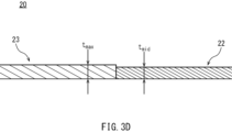
- FIG. 3D is a schematic diagram for explaining the manufacturing method of a structural member according to the first embodiment, and is a diagram showing a blank according to the first embodiment.
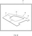
- FIG. 3E is a schematic diagram for explaining the manufacturing method of a structural member according to the first embodiment.
- FIG. 3F is a schematic diagram for explaining the manufacturing method of the structural member according to the first embodiment.
- FIG. 3G is a schematic view for explaining the manufacturing method of a structural member according to the first embodiment.
- FIG. 4 is a cross-sectional view of a structural member manufactured by the manufacturing method according to the first embodiment.
- FIG. 5 is a plan view of a blank according to the second embodiment.
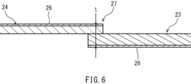
- FIG. 6 is a cross-sectional view taken along line VI-VI of FIG. FIG.
- FIG. 7 is a plan view of a structural member according to the second embodiment.
- FIG. 8 is a plan view of a structural member according to a modified example of each embodiment.
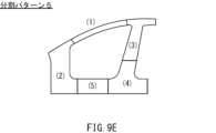
- FIG. 9A is a diagram showing a division pattern of a structural member in the first embodiment.
- FIG. 9B is a diagram showing another division pattern of the structural member in the first embodiment.
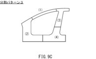
- FIG. 9C is a diagram showing yet another division pattern of the structural member in the first embodiment.
- FIG. 9D is a diagram showing yet another division pattern of the structural member in the first embodiment.
- FIG. 9E is a diagram showing yet another division pattern of the structural member in the first embodiment.
- FIG. 9F is a diagram showing yet another division pattern of the structural member in the first embodiment.
- FIG. 9A is a diagram showing a division pattern of a structural member in the first embodiment.
- FIG. 9B is a diagram showing another division pattern of the structural member in the first embodiment.
- FIG. 9C is a diagram showing yet another division pattern of the structural
- FIG. 9G is a diagram showing yet another division pattern of the structural member in the first embodiment.
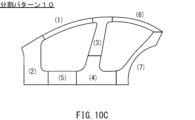
- FIG. 10A is a diagram showing a division pattern of a structural member in the second embodiment.
- FIG. 10B is a diagram showing another division pattern of the structural member in the second embodiment.
- FIG. 10C is a diagram showing yet another division pattern of the structural member in the second embodiment.
- FIG. 10D is a diagram showing yet another division pattern of the structural member in the second embodiment.
- the blank for hot stamping includes a plurality of steel plates.
- the plurality of steel plates are arranged and joined to have a ring shape in a plan view of the blank.
- the plurality of steel plates include a first steel plate and a second steel plate.
- the first steel plate has the smallest plate thickness among the plurality of steel plates.
- the second steel plate has a plate thickness greater than the plate thickness of the first steel plate.
- the first steel plate is configured such that the emissivity of at least one of both surfaces of the first steel plate is greater than the emissivity of both surfaces of the second steel plate (first configuration).
- the blank according to the first configuration includes a first steel plate having a minimum thickness and a second steel plate having a thickness greater than that of the first steel plate.
- the emissivity of at least one surface of the first steel plate is greater than the emissivity of both surfaces of the second steel plate. This allows the heating rate of the first steel plate, which is the thin-walled portion, to be increased when the blank is heated during hot stamping. Therefore, the first steel plate can be heated to the austenite region temperature more quickly, and the first steel plate can be held at that temperature for a long time. This allows the austenite crystal grains in the first steel plate to be coarsened.
- the ferrite transformation region (ferrite nose) in the CCT diagram shifts to the long-time side, so that after heating of the blank is completed, the start of the transformation to ferrite in the first steel plate can be delayed, and the blank can be formed while maintaining the microstructure of the first steel plate in the austenite phase.
- the hardenability of the first steel plate having a small thickness can be improved.
- the hardenability of the first steel plate which has a smaller plate thickness, is improved, so that the first steel plate can also be well hardened when the structural member is formed from the blank by hot stamping.
- This makes it easier to make the hardness of the structural member uniform, and it is possible to suppress partial reduction in strength of the structural member.
- uneven stress is less likely to occur in the structural member, even if the formed structural member is annular, twisting is less likely to occur, and good dimensional accuracy can be ensured in the structural member.
- annular structural member particularly a large and annular structural member, including the first steel plate, which has a smaller plate thickness than the second steel plate, is formed from a blank, it is possible to reduce poor strength and dimensional accuracy of the structural member, and improve the impact absorption performance (crash resistance) of the structural member.
- the emissivity of the first steel plate with the minimum thickness is greater than that of the second steel plate with a relatively large thickness.
- the first steel plate heats up faster than the second steel plate, and the high-temperature holding time of the first steel plate, that is, the time from when the first steel plate reaches the temperature in the austenite range to when the second steel plate and the entire blank reach the temperature in the austenite range, is longer than when the first steel plate has the same emissivity as the second steel plate. This reduces unevenness in phase transformation caused by differences in cooling rates between the steel plates after heating of the blank is completed.
- the start of the phase transformation from austenite to ferrite can be delayed for the first steel plate with the minimum thickness, and the difference in the start time of phase transformation between the first steel plate with the minimum thickness and the other steel plates is reduced. As a result, the hardenability can be made uniform between the first steel plate with the minimum thickness and the other steel plates.
- the first steel plate may have a plate thickness of less than 1.4 mm (second configuration).
- the first steel plate When the thickness of the first steel plate is less than 1.4 mm as in the second configuration, the first steel plate is particularly susceptible to heat dissipation after heating of the blank is complete, making the hardenability of the first steel plate more likely to deteriorate.
- the thickness of the first steel plate is less than 1.4 mm, by making the emissivity of at least one surface of the first steel plate higher than that of the relatively thick second steel plate, it is possible to promote the temperature rise of the first steel plate when the blank is heated during hot stamping, thereby ensuring a long high-temperature retention time for the first steel plate. Therefore, the hardenability of the first steel plate can be improved.
- the first steel sheet may be a plated steel sheet.
- the first steel sheet may have a base steel sheet and an aluminum-based plating layer provided on the base steel sheet (third configuration).
- the rate of temperature rise of the first steel sheet tends to be slow when the blank is heated during hot stamping.
- the aluminum-based plating layer is close to white and therefore tends to reflect thermal energy, inhibiting the temperature rise of the first steel sheet.
- the first steel sheet is a plated steel sheet having an aluminum-based plating layer, by making the emissivity of at least one surface of the first steel sheet higher than that of the relatively thick second steel sheet, it is possible to promote the temperature rise of the first steel sheet when the blank is heated during hot stamping. This allows the first steel sheet to be held at a high temperature for a long time, improving the hardenability of the first steel sheet.
- At least one surface of the first steel plate may be coated with a coating having an emissivity of 60% or more at a wavelength of 8.0 ⁇ m at 25°C (fourth configuration).
- At least one surface of the first steel plate may be coated with a coating.
- This coating may contain carbon black, one or more oxides selected from the group consisting of Zr oxide, Zn oxide, and Ti oxide, and 0 to 0.30 g/m 2 of silica.
- the carbon black content in the coating is X CB (g/m 2 ) and the oxide content is X Oxide (g/m 2 )
- X CB and X Oxide satisfy the following formula (1) (see Patent Document 1) (fifth configuration). 118.9 ⁇ 24280/ ⁇ 6700/(100+76 ⁇ X CB )+18000/(130+65 ⁇ X Oxide ) ⁇ 332.0
- the first steel sheet may be a plated steel sheet having a base steel sheet and a plating layer provided on the base steel sheet.
- the sheet thickness of the first steel sheet is t min and the sheet thickness of the steel sheet having the maximum sheet thickness among the plurality of steel sheets is t max , it is preferable that 1.0 ⁇ t max /t min ⁇ 3.2 (sixth configuration).
- the difference in thickness between the first steel sheet having the minimum sheet thickness t min and the other steel sheets having the maximum sheet thickness t max is large, it becomes difficult to ensure the process window in the manufacture of structural members.
- the difference between the minimum sheet thickness t min and the maximum sheet thickness t max is large, when the blank is heated for hot stamping, while waiting for the steel sheet having the maximum sheet thickness t max to reach the austenite temperature, alloying of the coating layer of the first steel sheet that has been heated to the austenite temperature in advance progresses, and the diffusion layer becomes thick, so that the corrosion resistance or weldability of the first steel sheet due to the coating layer cannot be ensured.
- the ratio of the maximum sheet thickness t max to the minimum sheet thickness t min is set to 3.2 or less.
- the heating rate of the steel plate having the maximum plate thickness tmax does not deviate too much from the heating rate of the first steel plate having the minimum plate thickness tmin , so that heating of the other steel plates can be completed before alloying of the coating layer of the first steel plate progresses excessively. Therefore, a structural member can be manufactured while maintaining the corrosion resistance or weldability of the first steel plate, and a process window in the manufacture of the structural member can be secured.
- the first steel sheet may be a plated steel sheet having a base steel sheet and a plating layer provided on the base steel sheet.
- the blank may further include an overlapping portion.
- the overlapping portion is formed by overlapping the ends of two adjacent steel sheets among the plurality of steel sheets, other than the second steel sheet.
- the overlapping portion may have a total sheet thickness of more than 2.5 mm and not more than 4.0 mm.
- it is preferable that the two steel sheets are each configured so that the emissivity of the surface located outside the overlapping portion is greater than the emissivity of both surfaces of the second steel sheet (seventh configuration).
- the emissivity of the outer surface of the overlapping portion is increased in each of the two steel sheets forming the overlapping portion. This can promote the temperature rise of the overlapping portion, so that the heating of the overlapping portion can be completed before the alloying of the plating layer of the first steel sheet progresses excessively, and the structural component can be manufactured while maintaining the corrosion resistance or weldability of the first steel sheet. In other words, it is easier to ensure the process window in the manufacture of structural components.
- the total plate thickness of the overlapping portion be 4.0 mm or less.
- the manufacturing method for a structural member according to the embodiment includes the steps of preparing a blank according to any one of the first to seventh configurations, heating the multiple steel plates contained in the blank to an austenite transformation completion temperature or higher, and using a die to form the heated blank into a structural member that is annular in plan view and quenching it (eighth configuration).
- a structural member includes a member body and a coating.
- the member body is formed of a plurality of steel plates joined together and has an annular shape in a plan view.
- the plurality of steel plates include a first steel plate having a minimum plate thickness and a second steel plate having a plate thickness greater than the plate thickness of the first steel plate.
- the coating is provided on the first steel plate.
- the coating contains 0.001 g/ m2 or more of one or more oxides selected from the group consisting of Zr oxide, Zn oxide, and Ti oxide (ninth configuration).
- a structural member includes a member body and a coating.
- the member body is formed of a plurality of steel plates joined together and has an annular shape in a plan view.
- the plurality of steel plates include a first steel plate having a minimum plate thickness and a second steel plate having a plate thickness greater than the plate thickness of the first steel plate.
- the coating is provided on the first steel plate.
- the coating contains carbon black in an amount of 0.500 g/m2 or less (tenth configuration).
- the structural member may be a door ring part of an automobile.
- the member body may include a front pillar, a center pillar, and a rocker connecting the front pillar and the center pillar (eleventh configuration).
- First Embodiment [Structural Members] 1 is a diagram (plan view) of a structural member 10 according to the present embodiment, viewed from above in a state in which the structural member 10 is placed on a horizontal surface.
- the structural member 10 is used, for example, in the body of an automobile.
- the structural member 10 is typically a door ring part of an automobile. In the present embodiment, an example in which the structural member 10 is a door ring part will be described.
- the structural member 10 is a hot stamped member. That is, the structural member 10 is formed by hot stamping (hot press processing) a blank made of multiple steel plates.
- the structural member 10 includes a member body 11.
- the member body 11 has an annular shape in a plan view of the structural member 10.
- the member body 11 includes a front pillar 111, a center pillar 112, and a rocker 113.
- the center pillar 112 is disposed behind the front pillar 111.
- the center pillar 112 extends generally in the vertical direction of the vehicle body.
- the front pillar 111 extends toward the center pillar 112.
- the rocker 113 is disposed below the front pillar 111 and the center pillar 112.
- the rocker 113 connects the front pillar 111 and the center pillar 112.
- the member body 11 is formed from a plurality of steel plates 21, 22, and 23 joined together.
- the front pillar 111 is mainly composed of the steel plates 21 and 22.
- the center pillar 112 is mainly composed of the steel plate 23.
- the rocker 113 is composed of the steel plates 21 and 23.
- FIG. 2 is a cross-sectional view taken along line II-II of FIG. 1.
- FIG. 2 shows a cross-section of the structural member 10 cut along the thickness direction at the position of the steel plate 21.
- the steel plate 21 has an open cross-section.
- the steel plate 21 has, for example, a roughly hat-shaped shape in the cross-sectional view of the structural member 10. More specifically, the steel plate 21 includes a top plate 211, vertical walls 212 and 213, and flanges 214 and 215.
- the vertical wall 212 is disposed on the opposite side of the vertical wall 213 with respect to the top plate 211. In the cross-sectional view of the structural member 10, one end of the vertical walls 212 and 213 is connected by the top plate 211.
- the other end of the vertical walls 212 and 213 is connected to the flanges 214 and 215, respectively.
- the flanges 214 and 215 protrude from the vertical walls 212 and 213 to the outside of the structural member 10.
- the width W of the steel plate 21 may be 30 mm or more and 750 mm or less.
- the height H of the steel plate 21 may be 25 mm or more and 150 mm or less.
- the width W is the distance from the end of the R on the vertical wall 212 side of the corner portion between the top plate 211 and the vertical wall 212 to the end of the R on the vertical wall 213 side of the corner portion between the top plate 211 and the vertical wall 213 in the cross section of the structural member 10.
- the height H is the distance from the top plate 211 to the flanges 214, 215 along the plate thickness direction of the top plate 211.
- the other steel plates 22, 23 also have an open cross section like the steel plate 21.
- the steel plates 22, 23 can also have, for example, a roughly hat shape in the cross section of the structural member 10.
- the width of the steel plates 22, 23 may be 15 mm or more and 300 mm or less.
- the height of the steel plates 22, 23 may be 10 mm or more and 150 mm or less.
- the size of the structural member 10, which is annular in plan view, is, for example, 1.0 m or more.
- the size of the structural member 10 may be, for example, 4.0 m or less.
- the size of the structural member 10 is the length of the line segment connecting any two points on the outer periphery of the structural member 10 that are farthest apart when the structural member 10 is placed on a horizontal surface and viewed vertically.
- the method for manufacturing the structural member 10 includes the steps of preparing a blank 20, heating the blank 20, and forming the heated blank 20 into the structural member 10.
- a blank 20 having a shape obtained by developing the structural member 10 is prepared.
- the blank 20 includes a plurality of steel plates 21, 22, and 23.
- the steel plates 21, 22, and 23 are arranged and joined to have an annular shape in a plan view of the blank 20.
- FIGS. 3B, 3C, and 3D are cross-sectional views of the blank 20 showing the joints of the steel plates 21, 22, and 23.
- FIGS. 3B, 3C, and 3D are cross-sectional views taken along lines IIIB-IIIB, IIIC-IIIC, and IIID-IIID in FIG. 3A, respectively.
- the steel plate 21 is butt-joined to each of the steel plates 22 and 23. That is, the end faces of the steel plate 21 are joined in a state where the end face of the steel plate 21 abuts against the end face of the steel plate 22, and the other end face of the steel plate 21 is joined in a state where the end face of the steel plate 21 abuts against the end face of the steel plate 23.
- the steel plate 22 is butt-joined to the steel plate 23 in addition to the steel plate 21.
- the end face of the steel plate 22 is joined to the end face of the steel plate 23 in a state where the end face of the steel plate 22 abuts against the end face of the steel plate 23.
- the steel plates 21, 22, and 23 are joined by, for example, laser welding.
- the blank 20 is a so-called tailor weld blank.
- the steel plate 21 has a minimum plate thickness t min .
- the steel plate 22 has a plate thickness larger than the plate thickness t min of the steel plate 21.
- the steel plate 23 has a plate thickness equal to or larger than the plate thickness t min of the steel plate 21.
- the plate thicknesses of the steel plates 22 and 23 are each larger than the plate thickness t min of the steel plate 21.
- the steel plate 23 has a maximum plate thickness t max among the steel plates 21, 22, and 23.
- the steel plate 22 has a plate thickness t mid that is larger than the plate thickness t min of the steel plate 21 and smaller than the plate thickness t max of the steel plate 23.
- the steel plate 22 may have a plate thickness equal to or larger than the steel plate 23. That is, among the steel plates 21, 22, and 23, the steel plate 22 may have a maximum plate thickness t max .
- the sheet thickness tmin of the steel plate 21 is typically less than 1.4 mm.
- the sheet thickness tmin may be, for example, 0.8 mm or more.
- the sheet thickness tmin of the steel plate 21 and the sheet thickness tmax of the steel plate 23 preferably satisfy 1.0 ⁇ tmax / tmin ⁇ 3.2, and more preferably satisfy 1.3 ⁇ tmax / tmin ⁇ 3.2.
- the steel plate 21 having the minimum thickness t min in the blank 20 is configured so that the emissivity of at least one of its two surfaces is greater than the emissivity of both surfaces of the steel plate 22.
- the emissivity at a wavelength of 8.0 ⁇ m at 25° C. is 60% or more on one or both surfaces of the steel plate 21 and less than 60% on both surfaces of the steel plate 22.
- the emissivity at a wavelength of 8.0 ⁇ m at 25° C. on one or both surfaces of the steel plate 21 is more preferably 70% or more, and even more preferably 80% or more.
- the emissivity between the steel plate 21 having the minimum thickness t min and the other steel plate 22 is preferably greater than 5%, more preferably greater than 10%, and even more preferably greater than 20%.
- the emissivity can be measured in accordance with JIS R 1801 (2002). In this case, a sample taken from the steel sheet to be measured is placed in a Fourier transform infrared spectrophotometer, and the radiation intensity at a wavelength of 8.0 ⁇ m is measured at 25° C. to calculate the emissivity. Alternatively, it is also possible to use a radiation thermometer set to a measurement wavelength of 8.0 ⁇ m to measure the radiation intensity of a site of interest at 25° C., and calculate the emissivity from the ratio to the radiation intensity of a black body.
- one surface of the steel plate 21 is covered with a coating 26.
- the steel plate 22 is not provided with a coating 26.
- the emissivity of the one surface of the steel plate 21 is higher than the emissivity of both surfaces of the steel plate 22.
- the coating 26 is, for example, a black coating.
- the coating 26 may be a carbon-based surface treatment coating (a coating containing carbon (C)).
- the emissivity of the coating 26 at a wavelength of 8.0 ⁇ m at 25° C. is 60% or more, preferably 70% or more, and more preferably 80% or more. That is, the emissivity of the surface of the steel plate 21 to which the coating 26 is applied at a wavelength of 8.0 ⁇ m at 25° C. is 60% or more, preferably 70% or more, and more preferably 80% or more.
- the coating 26 may have an emissivity of 60% or more at a wavelength of 8.0 ⁇ m at 700° C.
- a surface treatment coating described in Patent Document 1 can be used.
- the coating 26 may contain carbon black and one or more oxides selected from the group consisting of Zr oxide, Zn oxide, and Ti oxide.
- the coating 26 may or may not contain silica. That is, the silica content of the coating 26 is 0 g/ m2 or more.
- the silica content of the coating 26 may be 0.30 g/m2 or less .
- the silica content is more preferably 0.10 g/m2 or less, and even more preferably 0.05 g/m2 or less .
- the carbon black and the oxides can be present dispersedly throughout the entire surface of the coating 26 that is perpendicular to the thickness direction of the steel sheet 21.
- the carbon black content is X CB (g/m 2 )
- the content of one or more oxides (metal oxides) selected from the group consisting of Zr oxide, Zn oxide, and Ti oxide is X Oxide (g/m 2 )
- X CB and X Oxide preferably satisfy the following formula (1): 118.9 ⁇ 24280/ ⁇ 6700/(100+76 ⁇ X CB )+18000/(130+65 ⁇ X Oxide ) ⁇ 332.0 (1)
- the value calculated by the central formula: 24280/ ⁇ 6700/(100+76 ⁇ XCB )+18000/(130+65 ⁇ XOxide ) ⁇ is preferably 119.0 or more, more preferably 170.0 or more, and even more preferably 220.0 or more.
- the value calculated by the central formula is preferably 330.0 or less, more preferably 310.0 or less, and even more preferably 300.0 or less.
- the dispersion state of the carbon black and the metal oxide in the coating 26 can be confirmed by performing a surface analysis of the coating 26 for elements derived from the carbon black (e.g., C) and elements derived from the oxide (Zr, Zn, and Ti) using an electron probe microanalyzer (EPMA).
- the carbon black content X CB can be measured by a cross-sectional analysis of the coating 26 using a transmission electron microscope (TEM). That is, a cross-sectional analysis of the coating 26 is performed by TEM-EDS analysis on an area of a predetermined size (thickness of the coating 26 ⁇ 5 ⁇ m), and the thickness of the coating 26 and the area ratio of particles having a carbon content of 70 mass% or more in the area are measured.
- TEM transmission electron microscope
- the oxide content X Oxide can be obtained by performing elemental analysis on the surface of the coating 26 using an X-ray fluorescence analyzer (ZSX Primus, manufactured by RIGAKU Corporation) and quantifying the amounts of metallic Zr, metallic Zn, and metallic Ti.
- the carbon black content X CB in the coating 26 is preferably 0.030 g/m 2 or more, and more preferably 0.100 g/m 2 or more.
- the carbon black content X CB may be set within a range that satisfies formula (1), and is preferably 0.800 g/m 2 or less, and more preferably 0.600 g/m 2 or less.
- the coating 26 can contain 5.0% or more of carbon black by volume, and preferably contains 8.0% or more of carbon black by volume.
- the coating 26 can also contain 40.0% or less of carbon black by volume, and preferably contains 30.0% or less of carbon black by volume.
- the content X Oxide of the metal oxide in the coating 26 is preferably 0.030 g/m 2 or more, and more preferably 0.060 g/m 2 or more.
- the content X Oxide may be set within a range that satisfies the formula (1), and is preferably 0.500 g/m 2 or less, and more preferably 0.300 g/m 2 or less.
- the coating 26 can contain 1.0 or more volume percent of metal oxide.
- the coating 26 can also contain 30.0 or less volume percent of metal oxide, and preferably contains 25.0 or less volume percent of metal oxide.
- the ratio of the carbon black content XCB (g/ m2 ) to the metal oxide content XOxide (g/ m2 ): XOxide / XCB is preferably 0.20 or more and 200.00 or less, more preferably 0.40 or more and 10.00 or less , and further preferably 0.60 or more and 5.00 or less .
- the coating 26 may contain various binder components and additives in addition to the carbon black and metal oxides described above.
- the binder component is preferably a water-dispersible or water-soluble resin.
- the content of the binder component is preferably 40% by volume or more with respect to the total volume of the film 26.
- the binder component selected from the water-dispersible or water-soluble resins various known resins exhibiting water dispersibility or water solubility can be used. Examples of such water-dispersible or water-soluble resins include polyurethane resins, polyester resins, acrylic resins, epoxy resins, fluororesins, polyamide resins, polyolefin resins, and polymer compounds obtained by hydrolysis and condensation polymerization of silane coupling agents.
- the binder component is one or more selected from the group consisting of polyester resins, polyurethane resins, polyolefin resins, acrylic resins, epoxy resins, fluororesins, and polyamide resins.
- the polyurethane resin is preferably a polyether-based polyurethane resin.
- the additives include, for example, a leveling agent, a water-soluble solvent, a metal stabilizer, and an etching inhibitor.
- the leveling agent is, for example, a nonionic or cationic surfactant.
- nonionic or cationic surfactants include polyethylene oxide or polypropylene oxide adducts, and acetylene glycol compounds.
- water-soluble solvents examples include alcohols such as ethanol, isopropyl alcohol, t-butyl alcohol, and propylene glycol, cellosolves such as ethylene glycol monobutyl ether and ethylene glycol monoethyl ether, esters such as ethyl acetate and butyl acetate, and ketones such as acetone, methyl ethyl ketone, and methyl isobutyl ketone.
- metal stabilizers include chelate compounds such as EDTA (ethylenediaminetetraacetic acid) and DTPA (diethylenetriaminepentaacetic acid).
- etching inhibitors include amine compounds such as ethylenediamine, triethylenepentamine, guanidine, and pyrimidine.
- the coating 26 can be formed by applying an organic or inorganic treatment liquid containing, for example, carbon black and a metal oxide to the entire surface of the steel sheet 21, and then drying the volatile components in the treatment liquid.
- the treatment liquid can be applied to the surface of the steel sheet 21 by, for example, a roll coater, a curtain coater, or an inkjet. In the case of an inkjet, the film thickness of the coating 26 can also be changed continuously.
- the film thickness of the coating 26 is, for example, 0.5 ⁇ m or more and 5.0 ⁇ m or less.
- the film thickness of the coating 26 is preferably 1.0 ⁇ m or more and 3.0 ⁇ m or less.
- the film thickness of the coating 26 is negligibly small compared to the sheet thickness t min of the steel sheet 21. Therefore, the sheet thickness of the steel sheet 21 measured including the coating 26 can be treated as the sheet thickness t min of the steel sheet 21.
- the steel sheet 21 may be a plated steel sheet.
- the steel sheet 21 has a base steel sheet 216 and a plated layer 217.
- the type of base steel sheet 216 is not particularly limited.
- the plated layer 217 is provided on the base steel sheet 216.
- the plated layer 217 covers the entire or almost the entire both sides of the base steel sheet 216.
- the plated layer 217 is a metal plated layer.
- the plated layer 217 may be, for example, hot-dip aluminum plating, hot-dip galvanizing, alloyed hot-dip galvanizing, or electrolytic galvanizing.
- a known aluminum-plated steel sheet, zinc-plated steel sheet, etc. may be used as the steel sheet 21.
- the plating layer 217 is typically a plating layer containing aluminum as a main component (aluminum-based plating layer).
- the configuration of the aluminum-based plating layer is not particularly limited.
- a known aluminum-based plating layer can be adopted as the plating layer 217.
- the sheet thickness t min of the steel sheet 21 is the combined sheet thickness of the base steel sheet 216 and the plating layer 217.
- the steel sheets 22 and 23 may be known plated steel sheets, similar to the steel sheet 21.
- the steel sheets 22 and 23 may be aluminum plated steel sheets or zinc plated steel sheets.
- the steel sheets 22 and 23 may be the same type of plated steel sheet as the steel sheet 21, or may be a different type of plated steel sheet from the steel sheet 21.
- the steel sheet 22 may be the same type of plated steel sheet as the steel sheet 23, or may be a different type of plated steel sheet from the steel sheet 23.
- the sheet thickness t mid of the steel sheet 22 is the combined sheet thickness of the base steel sheet and the plating layer.
- the sheet thickness t max of the steel sheet 23 is the combined sheet thickness of the base steel sheet and the plating layer.
- the coating weight of each steel sheet may be the same as or different from that of the other steel sheets.
- the prepared blank 20 is formed into the structural member 10 (FIGS. 1 and 2) by hot stamping. During the hot stamping, the blank 20 is subjected to a heating step. Referring to FIG. 3E, in the heating step, the blank 20 is heated, for example, by a heating furnace 30.
- the multiple steel plates 21, 22, and 23 included in the blank 20 are heated to an austenite transformation completion temperature (A c3 point) or higher.
- the steel plates 21, 22, and 23 are heated, for example, to 900° C. or higher.
- the microstructures of the steel plates 21, 22, and 23 are transformed, for example, entirely or almost entirely into the austenite phase.
- the heated blank 20 is formed into an annular structural member 10 (Figs. 1 and 2) in a plan view using a die 40 and quenched.
- the blank 20 heated in the heating process is removed from the heating furnace 30 (Fig. 3E) and transported to the die 40.
- the die 40 is attached to a known press device.
- the die 40 includes, for example, a punch 41 and a die 42.
- the blank 20 is disposed between the punch 41 and the die 42.
- the die 42 approaches relatively to the punch 41.
- the blank 20 is clamped (pressed) by the punch 41 and the die 42 and formed into a shape that conforms to the forming surfaces of the punch 41 and the die 42.
- the blank 20 remains clamped between the punch 41 and the die 42.
- the blank 20 is cooled (quenched) by the die 40 and its microstructure is transformed into martensite. This allows the structural member 10 to be manufactured from the blank 20.
- FIG. 4 is a cross-sectional view of the structural member 10 after hot stamping.
- FIG. 4 shows a cross-section of the structural member 10 at the position of the steel plate 21 (FIGS. 3B and 3C) to which the black coating 26 was applied at the stage of the blank 20.
- This structural member 10 includes a member body 11 and a coating 12.
- the coating 12 is provided on the steel plate 21.
- the black coating 26 (FIGS. 3B and 3C) applied to the steel plate 21 in the blank 20 becomes the coating 12 through hot stamping. If the coating 26 contains carbon black, this carbon black is almost completely lost due to high-temperature heating during hot stamping, but may remain on the member body 11.
- the coating 12 after hot stamping may not contain carbon black or may contain 0.500 g/m 2 or less of carbon black.
- the carbon black content in the coating 12 exceeds 0 g/m 2.
- the value calculated by the middle formula: 24280/ ⁇ 6700/(100+76 ⁇ X CB )+18000/(130+65 ⁇ X Oxide ) ⁇ is, for example, 120.0 or more and 150.0 or less.
- the coating 12 after hot stamping contains, for example, more than 0 g/m 2, more preferably 0.001 g/m 2 or more of one or more oxides (metal oxides) selected from the group consisting of Zr oxide, Zn oxide, and Ti oxide.
- the content of the metal oxide in the coating 12 is, for example, 0.500 g/m 2 or less .
- the coating 12 after hot stamping contains 0 to 0.30 g/m 2 of silica.
- the carbon black content, metal oxide content, and silica content in the coating 12 can be measured in the same manner as the coating 26 at the blank 20 stage.
- the vehicle body part is disassembled to obtain the ring-shaped structural member 10, and an analysis sample is obtained from this structural member 10, for example, by laser cutting.
- an analysis sample is obtained from each of the multiple steel plates included in the structural member 10.
- the analysis sample is obtained from the center or its vicinity of the top plate of each steel plate having an open cross section.
- the obtained analysis sample is adjusted by polishing the cross section to outside the heat-affected zone during laser cutting, etc., to create a sample for coating analysis.
- the surface analysis of the coating 12 for elements derived from carbon black (e.g., C) and elements derived from oxides (Zr, Zn, and Ti) is performed on this sample using EPMA, and the dispersion state of the carbon black and metal oxide in the coating 12 can be confirmed.
- the outermost layer of the structural member 10 is, for example, an electrodeposition coating film.
- the coating layer that is present below the electrodeposition coating film layer and above the alloyed metal plating layer is analyzed.
- the carbon black content XCB in the coating 12 can be measured by a cross-sectional analysis of the coating 26 using a TEM. That is, a cross-sectional analysis of the coating 12 is performed by TEM-EDS analysis on an area of a predetermined size (thickness of the coating 12 ⁇ 5 ⁇ m), and the thickness of the coating 12 and the area ratio of particles having a carbon content of 70 mass% or more in the area are measured.
- the oxide content X Oxide can be determined by performing elemental analysis of the coating layer that is present under the electrodeposition coating layer and over the alloyed metal plating layer using the above-mentioned X-ray fluorescence analyzer, and quantifying the amounts of metal Zr, metal Zn, and metal Ti.
- the variation in martensite fraction is, for example, 20% or less, where the difference between the maximum martensite fraction (%) and the minimum martensite fraction (%) is taken as the variation in martensite fraction.
- the variation in martensite fraction is preferably 15% or less, and more preferably 10% or less.
- the variation in martensite fraction can be measured as follows.
- 10 or more analysis samples are cut out from positions 20 mm or more away from the end and 10 mm or more away from each other, and then each is mirror-polished and etched with LePeller's reagent so that the plate thickness direction becomes the observation surface.
- the image analysis method involves obtaining the maximum brightness value Lmax and the minimum brightness value Lmin from the image, determining the portion having pixels with brightness from Lmax-0.3 (Lmax-Lmin) to Lmax as a white region, and calculating the ratio of the number of pixels in the white region to the total number of pixels to measure the martensite fraction.
- This image analysis is performed on a total of 30 observation fields of each analysis sample to determine the martensite fraction, and the average value is taken as the martensite fraction of each analysis sample.
- the difference between the maximum and minimum values of the martensite fraction in 10 or more analysis samples is defined as the variation in the martensite fraction in the cross section of the structural member 10 at the position of the steel plate 21 having the minimum plate thickness t min .
- the area fraction of martensite obtained by image analysis i.e., the area fraction of the white area
- the area fraction of the white area may contain a few percent of the area fraction of retained austenite.
- the variation in the martensite fraction is calculated as a difference, the impact is minor.
- steel plate 21 can have a tensile strength of, for example, 0.5 GPa or more, and preferably has a tensile strength of 1.0 GPa or more.
- steel plates 22 and 23 (FIG. 1) can have a tensile strength of, for example, 0.5 GPa or more, and preferably has a tensile strength of 1.0 GPa or more.
- At least one of steel plates 21, 22, and 23 may have a tensile strength of 1.5 GPa or more after the forming process.
- the tensile strength of each of steel plates 21, 22, and 23 may be the same as or different from the tensile strength of the other steel plates.
- the emissivity of one surface of the steel sheet 21 having the minimum sheet thickness t min is greater than the emissivity of both surfaces of the steel sheet 22 having a greater sheet thickness. That is, the surface of the steel sheet 21 is treated to increase the emissivity.
- the temperature rise rate of the steel sheet 21 is significantly higher than that of the steel sheet 22. Therefore, in the heating process, the steel sheet 21 can be quickly heated to a temperature in the austenite region to ensure a long high-temperature holding time of the steel sheet 21.
- the austenite grains in the microstructure of the steel sheet 21 become coarse, and the ferrite transformation region (ferrite nose) in the CCT diagram shifts to the long-time side. Therefore, it is possible to prevent the austenite from transforming into ferrite in the steel sheet 21 after it is removed from the heating furnace 30 and before the forming by the die 40 is started. Therefore, the forming of the blank 20 by the die 40 can be started while the microstructure of the steel plate 21 is maintained in the austenitic phase, and the hardenability of the steel plate 21 having the minimum plate thickness t min can be improved.
- the hardenability of the relatively thin steel plate 21 is improved, so that the hardness of the structural member 10 formed from the blank 20 can be made uniform. More specifically, even the steel plate 21 having the minimum plate thickness t min is well hardened, so that the variation in the martensite fraction in the steel plate 21 can be made 20% or less. As a result, for example, when a collision load is input to the structural member 10, deformation concentration is unlikely to occur, and the structural member 10 is more likely to exhibit high impact absorption performance. Therefore, even when an annular structural member 10 including a steel plate 21 having a small plate thickness, particularly a large and annular structural member 10, is formed from the blank 20, it is possible to reduce strength defects of the structural member 10 and improve the impact absorption performance of the structural member 10.
- hardenability-deficient parts i.e., hardness-deficient parts
- the hardenability of the relatively thin steel plate 21 is improved, which makes it less likely that uneven stress will occur in the structural member 10. Therefore, even when the annular structural member 10 is formed from an annular blank 20, twisting is less likely to occur in the structural member 10. Therefore, even when a ring-shaped structural member 10 including a thin steel plate 21 is formed from a blank 20, particularly when a large ring-shaped structural member 10 is formed, it is possible to reduce poor dimensional accuracy of the structural member 10 and improve the impact absorption performance of the structural member 10.
- the surface of the steel plate 21 with the minimum thickness t min is substantially covered with a black coating 26, while the steel plate 22 with a thickness greater than that of the steel plate 21 is not provided with the coating 26. Therefore, the emissivity of the surface of the steel plate 21 is greater than the emissivity of both surfaces of the steel plate 22. In this case, the steel plate 21 heats up faster than the steel plate 22, so the high-temperature retention time of the steel plate 21 is longer than when the steel plate 21 has the same emissivity as the steel plate 22. This makes it possible to reduce unevenness in phase transformation caused by the difference in cooling rate between the steel plates 21, 22, and 23 after the heating of the blank 20 is completed.
- the start of the phase transformation from austenite to ferrite can be delayed for the steel plate 21 with the minimum thickness t min , the difference in the start time of phase transformation between the steel plate 21 and the other steel plates 22 and 23 is reduced. As a result, the hardenability of the steel plates 21, 22, and 23 included in the blank 20 can be made uniform.
- the rate at which the temperature of the steel sheet 21 rises during the heating process is likely to be slow. Because the aluminum-based plating layer is white, it is likely to reflect thermal energy, which inhibits the temperature rise of the steel sheet 21.
- the surface of the steel sheet 21 is treated to increase the emissivity. Therefore, even if the steel sheet 21 is a plated steel sheet having an aluminum-based plating layer, the temperature rise of the steel sheet 21 during the heating process can be promoted and the high-temperature retention time of the steel sheet 21 can be ensured for a long time. Therefore, the hardenability of the thin steel sheet 21 can be ensured.
- the steel plate 21 having the minimum thickness t min first reaches the temperature in the austenite region, and then the steel plate 22 having the intermediate thickness t mid and the steel plate 23 having the maximum thickness t max reach the temperature in the austenite region in that order.
- the ratio of the minimum thickness t min to the maximum thickness t max : t max /t min is preferably 3.2 or less. This allows the steel plate 23 having the thickness t max to be sufficiently heated until the phase transformation to austenite is completed before the alloying of the plating layer 217 of the steel plate 21 having the thickness t min progresses excessively due to heating, causing the diffusion layer to grow and causing the corrosion resistance or weldability to be lost. Therefore, the process window can be secured in the manufacturing of the structural member 10.
- a coating 26 can be applied to the steel plate 21 in order to increase the emissivity of the steel plate 21.
- the emissivity of the coating 26 (at a temperature of 25°C and a wavelength of 8.0 ⁇ m) is, for example, 60% or more. This allows the steel plate 21 to be efficiently radiated and makes it easier to increase the temperature rise rate of the steel plate 21 in the heating process.
- the coating 26 may contain carbon black, one or more oxides selected from the group consisting of Zr oxide, Zn oxide, and Ti oxide, and 0 to 0.30 g/m 2 or less of silica.
- the carbon black content X CB (g/m 2 ) and the oxide content X Oxide (g/m 2 ) preferably satisfy the above formula (1).
- formula (1) specifies the relationship between the rate of increase (%) of the temperature rise rate (°C/s), the carbon black content X CB, and the oxide content X Oxide .
- Formula (1) indicates that carbon black mainly functions as a heat absorbing material in the range up to 700°C, and oxide mainly functions as a heat absorbing material in the range of 700°C or more.
- the carbon black and oxides can be present dispersedly throughout the surface of the coating 26 perpendicular to the thickness direction of the steel sheet 21. This makes it easier to uniformize the emissivity of the surface of the steel sheet 21. Therefore, in the heating process, the steel sheet 21 having the minimum thickness t min can be heated quickly and uniformly.
- the coating 26 may be a substantially black coating in order to increase the emissivity of the steel sheet 21 compared to an untreated steel sheet.
- the coating 26 may contain graphite or soot instead of or in addition to carbon black.
- the coating 26 may contain, for example, an acicular compound having a hexagonal crystal structure with an aspect ratio of 4 to 50 in order to increase the emissivity of the steel sheet 21.
- the compound having a hexagonal crystal structure is typically graphite (C), but may also be lanthanum silicate, magnesium diboride, beryllium oxide (beryllia), zinc oxide, ⁇ -quartz, goethite (NiS), wurtzite (ZnS), etc.
- Second Embodiment 5 is a plan view of a blank 20A according to the second embodiment.
- the blank 20 according to the first embodiment is a tailored blank in which steel plates 21, 22, and 23 are butt-joined to each other.
- the blank 20A according to this embodiment differs from the first embodiment mainly in the form of the joints of the steel plates.
- the blank 20A includes a plurality of steel plates 21, 22, 23, 24, and 25.
- the steel plates 21, 22, 23, 24, and 25 are arranged and joined to have an annular shape in a plan view of the blank 20.
- the steel plate 21 has a minimum plate thickness t min , and is configured so that the emissivity of at least one surface thereof is greater than the emissivity of both surfaces of the steel plate 22. Therefore, the blank 20A according to this embodiment can also achieve the same effects as the first embodiment.
- FIG. 6 is a cross-sectional view taken along line VI-VI in FIG. 5, showing a cross-section of the overlap portion 27.
- the overlap portion 27 is formed by overlapping the ends of two adjacent steel plates 23, 24.
- the end of the steel plate 23 is joined in an overlapping state to the end of the steel plate 24.
- the steel plates 23, 24 are joined to each other by, for example, spot welding or laser welding.
- the overlap portion 27 has a total thickness t.
- the total thickness t is the sum of the thicknesses of the steel plates 23 and 24. If at least one of the steel plates 23 and 24 is a plated steel plate, the total thickness t includes the thickness of the plated layer.
- the total thickness t of the overlap portion 27 is, for example, greater than 2.5 mm and less than or equal to 4.0 mm.
- the steel plate 23 is configured so that the emissivity of the surface located outside the overlap portion 27, i.e., the surface opposite the steel plate 24, is greater than the emissivity of both surfaces of the steel plate 22 ( Figure 5).
- the steel plate 24 is configured so that the emissivity of the surface located outside the overlap portion 27, i.e., the surface opposite the steel plate 23, is greater than the emissivity of both surfaces of the steel plate 22. That is, in each of the steel plates 23 and 24, the surface located outside the overlap portion 27 is treated to increase the emissivity throughout its entirety.
- the emissivity at a wavelength of 8.0 ⁇ m at 25° C. is 60% or more, preferably 70% or more, and more preferably 80% or more, on the surfaces of the steel plates 23 and 24 located outside the overlap portion 27.
- the emissivity of the surfaces of the steel plates 23 and 24 located outside the overlap portion 27 may be greater than the emissivity of both surfaces of the steel plate 22, or may be less than the emissivity of both surfaces of the steel plate 22.
- the surface located outside the overlap portion 27 may be covered with a coating 26, so that the emissivity of the surface may be greater than that of the steel plate 22 ( Figure 5).
- the coating 26 used in the steel plates 23 and 24 may have a similar configuration to the coating 26 used in the steel plate 21. As described above, the thickness of the coating 26 is very small, so the total plate thickness t of the overlap portion 27 may be the plate thickness measured including the coating 26.
- the overlap portion 27 is difficult to heat up, so that when the blank 20A is heated during hot stamping, the plating layer 217 (FIGS. 3B and 3C) of the steel sheet 21 having the minimum thickness t min is alloyed and the diffusion layer grows before the overlap portion 27 reaches the austenite temperature range, which may make it impossible to ensure the corrosion resistance or weldability of the steel sheet 21.
- the emissivity of the overlap portion 27 is increased to promote the temperature rise, so that even if the total thickness t of the overlap portion 27 is greater than 2.5 mm, the overlap portion 27 can be sufficiently heated until the phase transformation to austenite is completed before the alloying of the plating layer 217 of the steel sheet 21 progresses and the diffusion layer becomes thicker, causing the corrosion resistance or weldability to be lost. Therefore, a process window can be secured in the manufacture of structural members.
- the steel plate 21 may be butt-joined to the steel plates 22 and 23, or may form an overlap portion 27 with one or both of the steel plates 22 and 23.
- the steel plate 25 may be butt-joined to the steel plates 22 and 24, or may form an overlap portion 27 with one or both of the steel plates 22 and 24.
- the steel plates 21 and 23 may be configured so that the emissivity of the surface located outside the overlap portion 27 is greater than the emissivity of both surfaces of the steel plate 22.
- the steel plates 24 and 25 may be configured so that the emissivity of the surface located outside the overlap portion 27 is greater than the emissivity of both surfaces of the steel plate 22.
- FIG. 7 is a plan view of a structural member 10A manufactured from a blank 20A.
- the structural member 10A has roughly the same configuration as the structural member 10 of the first embodiment (FIGS. 1 and 2). However, in the structural member 10A, the member body 11 is formed from five steel plates 21, 22, 23, 24, and 25. The method of manufacturing the structural member 10A from the blank 20A is the same as in the first embodiment.
- the structural member 10A can have a size similar to that of the structural member 10 according to the first embodiment. That is, the size of the structural member 10A, which is annular in plan view, is, for example, 1.0 m or more and 4.0 mm or less.
- each of the steel plates 21, 22, 23, 24, and 25 has an open cross section similar to that of the first embodiment.
- Each of the steel plates 21, 22, 23, 24, and 25 can have, for example, a roughly hat shape in a cross-sectional view of the structural member 10A.
- the width of the steel plate 21 arranged on the upper part of the front pillar 111 is, for example, 15 mm or more and 300 mm or less.
- the height of the steel plate 21 may be 10 mm or more and 150 mm or less.
- the width of the steel plate 22 arranged on the lower part of the front pillar 111 is, for example, 30 mm or more and 750 mm or less.
- the height of the steel plate 22 may be 25 mm or more and 150 mm or less.
- the width of the steel plates 23 and 24 arranged at the position of the center pillar 112 is, for example, 15 mm or more and 300 mm or less.
- the height of the steel plates 23 and 24 may be 10 mm or more and 150 mm or less.
- the width of the steel plate 25 arranged at the position of the locker 113 is, for example, 30 mm or more and 300 mm or less.
- the height of the steel plate 25 may be 25 mm or more and 150 mm or less.
- the surface of the steel plate 21 is covered with the coating 26.
- the method of increasing the emissivity of the surface of the steel plate 21 is not limited to the coating 26.
- the emissivity of the surface of the steel plate 21 can be increased more than that of the steel plate 22 by making the surface roughness of the steel plate 21 larger than that of the steel plate 22.
- the method of increasing the emissivity of the outer surface of the overlap portion 27 is not limited to the coating 26.
- the emissivity of only one of the two surfaces of the steel plate 21 having the minimum plate thickness t min is made higher than the emissivity of the steel plate 22.
- the emissivity of both surfaces of the steel plate 21 may be made higher than the emissivity of the steel plate 22.
- both surfaces of the steel plate 21 may be covered with the coating 26.
- the surface roughness of both surfaces of the steel plate 21 may be made higher than the surface roughness of the steel plate 22.
- the steel plates 21, 22, and 23 included in the blank 20 may each be single-layered or multi-layered. That is, the steel plates 21, 22, and 23 may each be a single steel plate or a plate material formed by stacking multiple steel plates. Similarly, in the second embodiment, the steel plates 21, 22, 23, 24, and 25 may each be single-layered or multi-layered.
- the blank 20 includes three steel plates 21, 22, and 23.
- the blank 20A includes five steel plates 21, 22, 23, 24, and 25.
- the blank 20, 20A may include at least a steel plate 21 having a minimum plate thickness t min and a steel plate 22 having a plate thickness greater than the plate thickness t min .
- the emissivity of one side or both sides of the steel plate 21 is greater than the emissivity of both sides of the steel plate 22.
- the steel plate 21 is directly or indirectly joined to the steel plate 22.
- the blank 20, 20A which is annular in plan view, may typically include three or more steel plates.
- the steel plates other than the steel plates 21 and 22 may or may not be treated to increase the emissivity.
- the emissivity of one side or both sides of all of the steel plates 21 is higher than the emissivity of both sides of the other steel plates 22.
- the arrangement of the multiple steel plates including the steel plates 21, 22 is not particularly limited.
- the steel sheet 21 having the minimum sheet thickness t min is a plated steel sheet.
- the steel sheet 21 does not necessarily have to be a plated steel sheet.
- the steel sheet 21 may be a steel sheet (bare material) that does not have a plating layer on its surface.
- steel sheets other than the steel sheet 21 may also be plated steel sheets or bare materials.
- the die 40 used for hot stamping the blank 20 includes a punch 41 and a die 42.
- the configuration of the die 40 is not limited to the example described in the first embodiment.
- the die 40 can further include, for example, a pad and a blank holder.
- the main body 11 of the structural member 10, 10A includes a front pillar 111, a center pillar 112, and a rocker 113.
- the member main body 11 can further include other components.
- the member main body 11 can further include a rear pillar 114.
- the structural members 10, 10A according to the above embodiment are door ring parts (single door ring parts) having a single ring shape.
- the structural member shown in FIG. 8 is a door ring part (double door ring part) having a double ring shape.
- the blank that serves as the material also has a double ring shape.
- the material type is listed in the following order: plating type, tensile strength, and application (hot stamping).
- the black coating is a black coating that contains carbon black and metal oxides.
- Black coating - one side means that one entire side of the steel sheet is covered with a black coating.
- Black coating - both sides means that both entire sides of the steel sheet are covered with a black coating.
- Figures 9A to 9G show the division pattern of the structural members.
- Figures 9A to 9G show the number of steel plates (materials) contained in the structural member, which is a single door ring part, and the positions of the joints between the steel plates in the structural member.
- each steel plate is given a number in parentheses.
- Table 2 shows the analysis conditions and results for division patterns 1 and 2 shown in Figures 9A and 9B.
- the structural member is formed from three pieces of material (1) to (3).
- Example 1 a black coating is applied to both sides of the material (3) having the smallest plate thickness t min : 1.2 mm among the materials (1) to (3).
- Example 2 a black coating is applied to one side of the material (1) having the smallest plate thickness t min : 1.2 mm among the materials (1) to (3).
- Example 3 a black coating is applied to both sides of the material (2) having the smallest plate thickness t min : 1.2 mm among the materials (1) to (3).
- Comparative Examples 1 and 2 a black coating is not applied to any of the materials (1) to (3).
- a black coating is not applied to the material having the smallest plate thickness t min : 1.2 mm.
- 910 ° C. arrival time refers to the time required from the start of heating the blank to reach 910 ° C. for the material that was heated to 910 ° C. (A c3 point or higher) the fastest among the materials contained in the blank.
- Phase transformation start time refers to the shortest time until the phase transformation to ferrite starts after the blank is heated at a furnace temperature of 920 ° C. for 5 minutes and 30 seconds and removed from the heating furnace. From Table 2, it can be seen that in Examples 1 to 3 in which the emissivity of the thinnest material is increased by the black coating, the time to reach 910 ° C.
- the phase transformation start time exceeds 20 seconds, which is later than the phase transformation start time in Comparative Examples 1 and 2. Therefore, it becomes easier to start forming the blank before the start of ferrite transformation, and it becomes possible to uniformly quench the blank in the forming process.
- Examples 4 to 10 a black coating is applied to the material having the smallest plate thickness t min among the materials (1) to (4).
- Examples 4 to 10 one or both sides of the material having the smallest plate thickness t min are covered with a black coating.
- a black coating is applied to all of these materials.
- Comparative Examples 3 to 7 a black coating is not applied to any of the materials (1) to (4).
- a black coating is not applied to the material having the smallest plate thickness t min .
- Table 4 shows the analysis conditions and results for division patterns 5 to 7 shown in Figures 9E to 9G.
- the structural members are formed from five pieces of material (1) to (5).
- a black coating is applied to the material having the smallest plate thickness t min among the materials (1) to (5).
- one or both sides of the material having the smallest plate thickness t min are covered with a black coating.
- a black coating is applied to all of these materials.
- Comparative Examples 8 to 11 a black coating is not applied to any of the materials (1) to (5).
- Comparative Examples 8 to 11 a black coating is not applied to the material having the smallest plate thickness t min .
- Example 16 and Comparative Example 12 material (2) and material (5), material (3) and material (4), and material (4) and material (5) form overlapping portions at their joints.
- Example 17 and Comparative Example 13 material (2) and material (5), and material (3) and material (4) form overlapping portions at their joints.
- the steel plates used as materials were selected from those shown in Table 1.
- the division pattern of the structural members is as shown in Figures 10A to 10D.
- Figures 10A to 10D show the number of steel plates (materials) contained in the structural members that are double door ring parts, and the positions of the joints between the steel plates in the structural members.
- each steel plate used as material is given a number in parentheses.
- a black coating is applied to the material having the smallest plate thickness t min among the materials (1) to (6).
- one or both sides of the material having the smallest plate thickness t min are covered with a black coating.
- a black coating is not applied to any of the materials (1) to (6).
- a black coating is not applied to the material having the smallest plate thickness t min .
- Examples 21 to 23 a black coating is applied to the material having the smallest plate thickness t min among the materials (1) to (7). In Examples 21 to 23, one or both sides of the material having the smallest plate thickness t min are covered with a black coating. On the other hand, in Comparative Examples 16 and 17, a black coating is not applied to any of the materials (1) to (7). In Comparative Examples 16 and 17, a black coating is not applied to the material having the smallest plate thickness t min .
- Table 7 shows that in Examples 21 to 23, the time to reach 910°C was shorter than in Comparative Examples 16 and 17, and the temperature rise rate of the thinnest material in the heating process was higher. Furthermore, in Examples 21 to 23, the phase transformation start time was slower than in Comparative Examples 16 and 17. This makes it easier to start forming the blank before the ferrite transformation begins, and makes it possible to uniformly quench the blank in the forming process.
- the division patterns of Test Examples 1 and 5 are division patterns 7 shown in FIG. 9G.
- the division pattern of Test Example 4 is division pattern 5 shown in FIG. 9E.
- some of the materials form overlapping portions at the joints. More specifically, in Test Examples 1 and 5, material (1) and material (2), material (1) and material (3), material (2) and material (5), and material (4) and material (5) each form overlapping portions at their joints.
- material (1) and material (2), material (1) and material (3), material (3) and material (4), and material (2) and material (5) each form overlapping portions at their joints.
- a black coating is applied to the material having the minimum plate thickness t min .
- a black coating is applied to both outer sides of the overlapping portion having the maximum total plate thickness t.
- Test Examples 2, 3, and 6 The division pattern of Test Examples 2, 3, and 6 is Division Pattern 7 shown in Fig. 9G.
- the materials are joined by butt joints.
- a black coating is applied to the material having the minimum plate thickness tmin .
- the "process window (PW)" in Table 8 is the allowable heating time for the material contained in the blank that reaches 910°C the earliest, minus the time it takes for the entire blank to reach 910°C after it first reaches 910°C. If the process window is 5 seconds or less, alloying of the plating layer of the material that reaches 910°C the earliest in the heating process will progress, meaning that the corrosion resistance of the plating layer cannot be ensured and good manufacturing of structural components will become difficult.
- test example 5 where the maximum total plate thickness t of the overlap portion exceeded 4.0 mm, the process window was negative and it was not possible to ensure the process window necessary for good manufacturing of structural components.
- test examples 1 and 4 where the maximum total plate thickness t of the overlap portion was greater than 2.5 mm and equal to or less than 4.0 mm, a process window of 5 seconds or more could be ensured.
- Reference Example 1 is an example of division pattern 5 similar to Test Example 4, but no black coating is applied to any of the materials, including the overlapping parts. However, in Reference Example 1, there is no difference in sheet thickness between the materials, and there is no problem with the progression of alloying of the plating layer in the thinnest material, so a process window of 5 seconds or more can be secured.
- the blanks were heated at a furnace temperature of 920°C until the entire blank reached 910°C, then transported to a press in 17 seconds and hot stamped at a forming speed of 40 mm/s, and held at bottom dead center for 20 seconds while applying a pressure of 3000 kN to obtain hot stamped structural components.
- Analysis samples were taken from the thinnest parts of these structural components using the method described in the above embodiment, and the variation in martensite fraction was measured. Separately, shape accuracy and impact absorption performance measurements were also performed on these structural components. The evaluation results are shown in Table 9.
- the variation in martensite fraction is the value obtained by subtracting the minimum martensite fraction (%) from the maximum martensite fraction (%) in the cross section of the structural member at the position of the material having the minimum plate thickness t min , as described in the above embodiment.
- the shape accuracy was evaluated based on how far apart the structural member was from the mating member at the overlapping portion of the structural member and mating member when the structural member was roughly hat-shaped in cross section and attached to another member.
- Table 9 cases where the distance from the surface of the mating member was within ⁇ 2.0 mm are marked with an O, cases where it was between ⁇ 2.0 mm and ⁇ 3.0 mm, and cases where it was over ⁇ 3.0 mm are marked with an X.
- impact absorption performance In terms of impact absorption performance, assuming a small overlap (SOL) collision and a side collision with the structural members installed in the vehicle, an impactor simulating a vehicle was collided with the structural members to evaluate the maximum intrusion amount during an SOL collision and the maximum intrusion amount during a side collision. Impact absorption performance was evaluated based on the impact absorption performance of each material formed by hot stamping and then joining to form a door ring part, and compared to the impact absorption performance of the base. In Table 9, impact absorption performance equivalent to the impact absorption performance of the base is displayed as good, impact absorption performance superior to the impact absorption performance of the base as better, impact absorption performance slightly lower than the impact absorption performance of the base as marginal, and even lower impact absorption performance as poor.
- Comparative Example 10 is a comparative example of the first embodiment, and similar to Test Example 2, the materials are butt-joined by laser.
- Comparative Example 13A is the same plate assembly as Comparative Example 13 of the first embodiment, but similar to Test Example 4, the materials are partially overlapped and joined. Unlike each test example, Comparative Example 10 and Comparative Example 13A do not have a black coating on any of the materials, including the thinnest material. As shown in Table 9, the variation in martensite fraction in all of Test Examples 1 to 4 was 20% or less, and the variation in martensite fraction was significantly reduced compared to Comparative Examples 10 and 13A. Test Examples 1 to 4 also had better shape precision compared to Comparative Examples 10 and 13A.
- Test Examples 1 to 4 where the variation in the martensite fraction was small, the impact absorption performance was improved compared to Comparative Examples 10 and 13A.
- Test Examples 1 to 3 where the variation in the martensite fraction was 15% or less, impact absorption performance equal to or greater than that of the base was ensured.
- the strength against axial force was improved by butt-joining the materials, so the impact absorption performance was better than that of Test Example 1.
- Test Examples 2 and 3 demonstrated high impact absorption performance, especially in SOL collisions.
Landscapes
- Chemical & Material Sciences (AREA)
- Engineering & Computer Science (AREA)
- Mechanical Engineering (AREA)
- Materials Engineering (AREA)
- Organic Chemistry (AREA)
- Metallurgy (AREA)
- Chemical Kinetics & Catalysis (AREA)
- Inorganic Chemistry (AREA)
- Thermal Sciences (AREA)
- Physics & Mathematics (AREA)
- Crystallography & Structural Chemistry (AREA)
- Combustion & Propulsion (AREA)
- Transportation (AREA)
- Oil, Petroleum & Natural Gas (AREA)
- Life Sciences & Earth Sciences (AREA)
- Wood Science & Technology (AREA)
- Heat Treatment Of Articles (AREA)
- Rod-Shaped Construction Members (AREA)
- Shaping Metal By Deep-Drawing, Or The Like (AREA)
Priority Applications (4)
| Application Number | Priority Date | Filing Date | Title |
|---|---|---|---|
| EP24797073.4A EP4703058A1 (en) | 2023-04-28 | 2024-04-24 | Blank, method for manufacturing structural member, and structural member |
| JP2024576464A JP7656248B2 (ja) | 2023-04-28 | 2024-04-24 | ブランク、構造部材の製造方法、及び構造部材 |
| CN202480027952.4A CN121001835A (zh) | 2023-04-28 | 2024-04-24 | 毛坯、结构部件的制造方法和结构部件 |
| MX2025012663A MX2025012663A (es) | 2023-04-28 | 2025-10-23 | Pieza en bruto, metodo de produccion de miembro estructural y miembro estructural |
Applications Claiming Priority (2)
| Application Number | Priority Date | Filing Date | Title |
|---|---|---|---|
| JP2023075316 | 2023-04-28 | ||
| JP2023-075316 | 2023-04-28 |
Publications (1)
| Publication Number | Publication Date |
|---|---|
| WO2024225327A1 true WO2024225327A1 (ja) | 2024-10-31 |
Family
ID=93256650
Family Applications (1)
| Application Number | Title | Priority Date | Filing Date |
|---|---|---|---|
| PCT/JP2024/016110 Ceased WO2024225327A1 (ja) | 2023-04-28 | 2024-04-24 | ブランク、構造部材の製造方法、及び構造部材 |
Country Status (5)
| Country | Link |
|---|---|
| EP (1) | EP4703058A1 (https=) |
| JP (1) | JP7656248B2 (https=) |
| CN (1) | CN121001835A (https=) |
| MX (1) | MX2025012663A (https=) |
| WO (1) | WO2024225327A1 (https=) |
Citations (6)
| Publication number | Priority date | Publication date | Assignee | Title |
|---|---|---|---|---|
| JP2021154370A (ja) * | 2020-03-30 | 2021-10-07 | 日本製鉄株式会社 | 重ね合わせブランク、および、それを用いたホットスタンプ成形体の製造方法 |
| JP7101730B2 (ja) * | 2020-08-21 | 2022-07-15 | 株式会社ジーテクト | 金型 |
| WO2022215229A1 (ja) | 2021-04-08 | 2022-10-13 | 日本製鉄株式会社 | ホットスタンプ用鋼板及びホットスタンプ部材 |
| JP7260765B2 (ja) * | 2019-03-29 | 2023-04-19 | 日本製鉄株式会社 | 熱間プレス成形品の製造方法、および鋼板 |
| WO2023224122A1 (ja) * | 2022-05-19 | 2023-11-23 | 日本製鉄株式会社 | ホットスタンプ用重ね合わせブランク、及び、重ね合わせホットスタンプ成形体 |
| JP2023180687A (ja) * | 2022-06-10 | 2023-12-21 | 株式会社キーレックス | 熱間プレス用ブランク材の製造方法及び熱間プレス用ブランク材 |
Family Cites Families (4)
| Publication number | Priority date | Publication date | Assignee | Title |
|---|---|---|---|---|
| KR101033767B1 (ko) | 2010-11-03 | 2011-05-09 | 현대하이스코 주식회사 | 열처리 경화 강판을 이용한 국부적으로 이종강도를 가지는 자동차 부품 제조방법 |
| JP6681239B2 (ja) | 2016-03-28 | 2020-04-15 | 日本製鉄株式会社 | プレス成形方法 |
| KR102454267B1 (ko) * | 2018-06-22 | 2022-10-17 | 닛폰세이테츠 가부시키가이샤 | 강판, 테일러드 블랭크, 열간 프레스 성형품, 강관, 중공형 ??칭 성형품, 및 강판의 제조 방법 |
| CN217893040U (zh) | 2022-08-12 | 2022-11-25 | 浙江吉利控股集团有限公司 | 侧围加强板、侧围加强板总成和车辆 |
-
2024
- 2024-04-24 EP EP24797073.4A patent/EP4703058A1/en active Pending
- 2024-04-24 CN CN202480027952.4A patent/CN121001835A/zh active Pending
- 2024-04-24 WO PCT/JP2024/016110 patent/WO2024225327A1/ja not_active Ceased
- 2024-04-24 JP JP2024576464A patent/JP7656248B2/ja active Active
-
2025
- 2025-10-23 MX MX2025012663A patent/MX2025012663A/es unknown
Patent Citations (6)
| Publication number | Priority date | Publication date | Assignee | Title |
|---|---|---|---|---|
| JP7260765B2 (ja) * | 2019-03-29 | 2023-04-19 | 日本製鉄株式会社 | 熱間プレス成形品の製造方法、および鋼板 |
| JP2021154370A (ja) * | 2020-03-30 | 2021-10-07 | 日本製鉄株式会社 | 重ね合わせブランク、および、それを用いたホットスタンプ成形体の製造方法 |
| JP7101730B2 (ja) * | 2020-08-21 | 2022-07-15 | 株式会社ジーテクト | 金型 |
| WO2022215229A1 (ja) | 2021-04-08 | 2022-10-13 | 日本製鉄株式会社 | ホットスタンプ用鋼板及びホットスタンプ部材 |
| WO2023224122A1 (ja) * | 2022-05-19 | 2023-11-23 | 日本製鉄株式会社 | ホットスタンプ用重ね合わせブランク、及び、重ね合わせホットスタンプ成形体 |
| JP2023180687A (ja) * | 2022-06-10 | 2023-12-21 | 株式会社キーレックス | 熱間プレス用ブランク材の製造方法及び熱間プレス用ブランク材 |
Also Published As
| Publication number | Publication date |
|---|---|
| CN121001835A (zh) | 2025-11-21 |
| JP7656248B2 (ja) | 2025-04-03 |
| JPWO2024225327A1 (https=) | 2024-10-31 |
| EP4703058A1 (en) | 2026-03-04 |
| MX2025012663A (es) | 2025-11-03 |
Similar Documents
| Publication | Publication Date | Title |
|---|---|---|
| JP6055831B2 (ja) | 自動車車体用のクラッドされた薄板 | |
| JP7477753B2 (ja) | 重ね合わせブランク、および、それを用いたホットスタンプ成形体の製造方法 | |
| WO2020209357A1 (ja) | ブランクおよび構造部材 | |
| JP7853467B2 (ja) | 優れたスポット溶接性および優れた塗装付着性を有する、薄いコーティングを有する亀裂含有ホットスタンプ鋼部品 | |
| JP7684626B2 (ja) | ブランク、構造部材の製造方法、及び構造部材 | |
| JP7656248B2 (ja) | ブランク、構造部材の製造方法、及び構造部材 | |
| US20250257437A1 (en) | Crack-containing hot-stamped coated steel part with excellent spot-weldability and excellent painting adhesion | |
| JP7684628B1 (ja) | 自動車リアモジュール | |
| JP7769278B1 (ja) | ブランク、構造部材の製造方法、及び構造部材 | |
| JP7656249B2 (ja) | ブランク、構造部材の製造方法、及び構造部材 | |
| JP7810935B2 (ja) | ブランク、構造部材の製造方法、及び構造部材 | |
| JP7741455B2 (ja) | ブランク、構造部材の製造方法、及び構造部材 | |
| JP2025146839A (ja) | ブランク、構造部材の製造方法、及び構造部材 | |
| JP7678401B1 (ja) | ブランク、構造部材の製造方法、及び構造部材 | |
| CA3289852A1 (en) | Blank, production method for structural member and structural member | |
| KR20220104211A (ko) | 사전-코팅된 강판으로 제조된 용접된 강 부품의 용접 금속 구역의 기계적 강도를 증가시키기 위한 추가 코팅을 포함하는 사전-코팅된 강판 | |
| CA3289833A1 (en) | Blank, production method for structural member and structural member | |
| JP7741456B2 (ja) | ブランク、構造部材の製造方法、及び構造部材 | |
| WO2025197171A1 (ja) | 自動車リアモジュール | |
| WO2025109968A1 (ja) | 自動車サイドモジュール | |
| KR20130125662A (ko) | 상온성형성이 향상된 클래드 판재 및 이의 제조방법 |
Legal Events
| Date | Code | Title | Description |
|---|---|---|---|
| 121 | Ep: the epo has been informed by wipo that ep was designated in this application |
Ref document number: 24797073 Country of ref document: EP Kind code of ref document: A1 |
|
| WWE | Wipo information: entry into national phase |
Ref document number: 2024576464 Country of ref document: JP |
|
| REG | Reference to national code |
Ref country code: BR Ref legal event code: B01A Ref document number: 112025022085 Country of ref document: BR |
|
| WWE | Wipo information: entry into national phase |
Ref document number: MX/A/2025/012663 Country of ref document: MX |
|
| WWP | Wipo information: published in national office |
Ref document number: MX/A/2025/012663 Country of ref document: MX |
|
| WWE | Wipo information: entry into national phase |
Ref document number: 202517110797 Country of ref document: IN |
|
| WWE | Wipo information: entry into national phase |
Ref document number: 2024797073 Country of ref document: EP |
|
| NENP | Non-entry into the national phase |
Ref country code: DE |
|
| ENP | Entry into the national phase |
Ref document number: 2024797073 Country of ref document: EP Effective date: 20251128 |
|
| ENP | Entry into the national phase |
Ref document number: 2024797073 Country of ref document: EP Effective date: 20251128 |
|
| WWP | Wipo information: published in national office |
Ref document number: 202517110797 Country of ref document: IN |
|
| ENP | Entry into the national phase |
Ref document number: 2024797073 Country of ref document: EP Effective date: 20251128 |
|
| ENP | Entry into the national phase |
Ref document number: 2024797073 Country of ref document: EP Effective date: 20251128 |
|
| ENP | Entry into the national phase |
Ref document number: 2024797073 Country of ref document: EP Effective date: 20251128 |
|
| ENP | Entry into the national phase |
Ref document number: 2024797073 Country of ref document: EP Effective date: 20251128 |
|
| ENP | Entry into the national phase |
Ref document number: 2024797073 Country of ref document: EP Effective date: 20251128 |
|
| ENP | Entry into the national phase |
Ref document number: 2024797073 Country of ref document: EP Effective date: 20251128 |
|
| ENP | Entry into the national phase |
Ref document number: 2024797073 Country of ref document: EP Effective date: 20251128 |
|
| WWP | Wipo information: published in national office |
Ref document number: 2024797073 Country of ref document: EP |