WO2024225217A1 - 融着機、光ファイバの接続方法 - Google Patents
融着機、光ファイバの接続方法 Download PDFInfo
- Publication number
- WO2024225217A1 WO2024225217A1 PCT/JP2024/015704 JP2024015704W WO2024225217A1 WO 2024225217 A1 WO2024225217 A1 WO 2024225217A1 JP 2024015704 W JP2024015704 W JP 2024015704W WO 2024225217 A1 WO2024225217 A1 WO 2024225217A1
- Authority
- WO
- WIPO (PCT)
- Prior art keywords
- optical fiber
- electrodes
- fiber
- pair
- axis
- Prior art date
- Legal status (The legal status is an assumption and is not a legal conclusion. Google has not performed a legal analysis and makes no representation as to the accuracy of the status listed.)
- Ceased
Links
Images


Classifications
-
- G—PHYSICS
- G02—OPTICS
- G02B—OPTICAL ELEMENTS, SYSTEMS OR APPARATUS
- G02B6/00—Light guides; Structural details of arrangements comprising light guides and other optical elements, e.g. couplings
- G02B6/24—Coupling light guides
- G02B6/255—Splicing of light guides, e.g. by fusion or bonding
- G02B6/2551—Splicing of light guides, e.g. by fusion or bonding using thermal methods, e.g. fusion welding by arc discharge, laser beam, plasma torch
-
- G—PHYSICS
- G02—OPTICS
- G02B—OPTICAL ELEMENTS, SYSTEMS OR APPARATUS
- G02B6/00—Light guides; Structural details of arrangements comprising light guides and other optical elements, e.g. couplings
- G02B6/02—Optical fibres with cladding with or without a coating
-
- G—PHYSICS
- G02—OPTICS
- G02B—OPTICAL ELEMENTS, SYSTEMS OR APPARATUS
- G02B6/00—Light guides; Structural details of arrangements comprising light guides and other optical elements, e.g. couplings
- G02B6/02—Optical fibres with cladding with or without a coating
- G02B6/02295—Microstructured optical fibre
- G02B6/02314—Plurality of longitudinal structures extending along optical fibre axis, e.g. holes
- G02B6/02319—Plurality of longitudinal structures extending along optical fibre axis, e.g. holes characterised by core or core-cladding interface features
- G02B6/02323—Core having lower refractive index than cladding, e.g. photonic band gap guiding
- G02B6/02328—Hollow or gas filled core
-
- G—PHYSICS
- G02—OPTICS
- G02B—OPTICAL ELEMENTS, SYSTEMS OR APPARATUS
- G02B6/00—Light guides; Structural details of arrangements comprising light guides and other optical elements, e.g. couplings
- G02B6/02—Optical fibres with cladding with or without a coating
- G02B6/032—Optical fibres with cladding with or without a coating with non solid core or cladding
-
- G—PHYSICS
- G02—OPTICS
- G02B—OPTICAL ELEMENTS, SYSTEMS OR APPARATUS
- G02B6/00—Light guides; Structural details of arrangements comprising light guides and other optical elements, e.g. couplings
- G02B6/24—Coupling light guides
- G02B6/255—Splicing of light guides, e.g. by fusion or bonding
-
- G—PHYSICS
- G02—OPTICS
- G02B—OPTICAL ELEMENTS, SYSTEMS OR APPARATUS
- G02B6/00—Light guides; Structural details of arrangements comprising light guides and other optical elements, e.g. couplings
- G02B6/24—Coupling light guides
- G02B6/255—Splicing of light guides, e.g. by fusion or bonding
- G02B6/2553—Splicing machines, e.g. optical fibre fusion splicer
-
- G—PHYSICS
- G02—OPTICS
- G02B—OPTICAL ELEMENTS, SYSTEMS OR APPARATUS
- G02B6/00—Light guides; Structural details of arrangements comprising light guides and other optical elements, e.g. couplings
- G02B6/24—Coupling light guides
- G02B6/255—Splicing of light guides, e.g. by fusion or bonding
- G02B6/2555—Alignment or adjustment devices for aligning prior to splicing
Definitions
- the present invention relates to a fusion splicer that can efficiently fuse optical fibers with special cross-sectional shapes, such as hollow core fibers and photonic bandgap fibers.
- a fusion splicer is used to connect optical fibers together.
- the fusion splicer uses a pair of electrodes as a heating source to melt the optical fibers. Glass optical fibers held in a pair of holders are butted together and placed between the electrodes, and high voltage is applied between the tips of the electrodes to generate an aerial discharge and fuse the optical fibers together (for example, see Patent Document 1).
- hollow core fibers confine light in an air tube, and have a fine internal structure to form this air tube.
- hollow core fibers have a thick glass wall on the outer periphery to ensure strength, and a thin glass partition is formed inside to form a fine air layer.
- the present invention was made in consideration of these problems, and aims to provide a fusion splicer etc. that can efficiently splice even special optical fibers such as hollow core fibers and photonic bandgap fibers.
- the first invention is a fusion splicer that connects optical fibers, comprising a holder mounting section on which a holder that holds the optical fiber is disposed, and at least a pair of electrodes that are disposed in a direction perpendicular to the axial direction of the optical fiber, the axis connecting the tips of the pair of electrodes is offset from the axis of the optical fiber, and the control section of the fusion splicer is capable of rotating the holder mounting section or the electrodes around the axis of the optical fiber so that the arrangement of the electrodes in the circumferential direction of the optical fiber is changed relatively.
- the control unit may be capable of rotating the holder mounting portion around the axis of the optical fiber.
- the control unit may be capable of rotating the electrode around the optical fiber around the axis of the optical fiber.
- the axis connecting the tips of a pair of electrodes is offset from the axis of the optical fiber, so that the arc generated between the electrodes can selectively melt the outer periphery of the optical fiber, rather than the center.
- the arrangement of the electrodes in the circumferential direction of the optical fiber is relatively changed, so that the entire circumference of the outer periphery of the optical fiber can be melted and connected.
- the outer periphery of the optical fiber can be reliably fusion-spliced while suppressing heating of the center, making it possible to fusion-splice even special optical fibers such as hollow-core fibers and photonic band-gap fibers.
- the entire circumference of the outer periphery of the optical fiber can be sequentially positioned between the electrodes. This allows the entire circumference of the optical fiber to be fusion spliced.
- the second invention is a method for connecting optical fibers using a fusion splicer equipped with a holder mounting portion on which a holder that holds an optical fiber is placed, and at least a pair of electrodes arranged in a direction perpendicular to the axial direction of the optical fiber, wherein an axis connecting the tips of the pair of electrodes is offset from the axis of the optical fiber, and a control portion of the fusion splicer rotates the holder mounting portion or the electrodes around the axis of the optical fiber so that the arrangement of the electrodes in the circumferential direction of the optical fiber is changed relatively to connect the optical fibers.
- the optical fiber is a hollow core fiber or an optical fiber consisting of a core and a cladding portion around the core, with at least one hole in the cladding portion, and discharge is performed on the outer periphery of the optical fiber to fuse the outer peripheries of the optical fiber together, and fusion may not be required inside the optical fiber.
- the optical fiber may be an optical fiber having a core and a cladding portion around the core, the core being multiple in number, and the optical fiber may be fused by discharging the outer periphery of the optical fiber so that the temperature distribution at the time of fusing the outer periphery of the optical fiber is higher than the temperature inside the optical fiber.
- the axis connecting the tips of a pair of electrodes is offset from the axis of the optical fiber, so that the arc generated between the electrodes can selectively melt the outer periphery of the optical fiber, rather than the center.
- the arrangement of the electrodes in the circumferential direction of the optical fiber is relatively changed, so that the entire circumference of the outer periphery of the optical fiber can be melted and connected.
- the outer periphery is securely fused to ensure connection strength, and the thin partition wall on the inner periphery of the optical fiber does not melt or melts only to a small extent, allowing the optical fibers to be fused together while maintaining the air layer.
- the diffusion of the core dopant can be promoted by sufficiently heating the cores near the outer periphery, which are more susceptible to the effects of core misalignment. This makes it possible to expand the mode field diameter of the cores on the outer periphery side, and suppress the effects of core misalignment.
- the present invention provides a fusion splicer and the like that can efficiently fuse even special optical fibers such as hollow core fibers and photonic bandgap fibers.
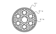
- FIG. Schematic cross-section of a hollow-core fiber.
- FIG. FIG. FIG. FIG. FIG. 3 is a cross-sectional view of a multi-core fiber 31.
- Fig. 1 is a perspective view of a fusion splicer 1.
- the fusion splicer 1 connects a pair of optical fibers by fusion. Note that in the following figures, configurations that are not necessary for the explanation are omitted.
- the fusion splicer 1 has a cover 3 that can be opened and closed relative to the main body.
- the main body also includes a holder mounting section 11 on which a holder that holds an optical fiber is mounted, an optical fiber holding section 5 that holds the tip of the optical fiber and positions it, an operation section 15 for performing various settings of the fusion splicer 1 and the alignment and fusion operations described below, and a display section 17 for displaying various information and images.
- the operation section 15 and the display section 17 may be integrated by making the display section 17 a touch panel.
- the optical fiber is held in a V-groove on the optical fiber holding part 5.
- a pair of electrodes 7 are arranged in a direction approximately perpendicular to the opposing direction of the pair of optical fibers (the axial direction of the optical fibers). The arrangement of the electrodes 7 will be described in detail later.
- the lid 3 can be opened and closed relative to the main body.
- a clamp 13 is provided on the back surface of the lid 3, and when the lid 3 is closed, the tip of the clamp 13 is located at a position corresponding to the position of the optical fiber on the optical fiber holding part 5.
- the clamp 13 provided on the back surface of the lid 3 can hold a pair of optical fibers facing each other in the optical fiber holding part 5.
- the optical fibers are first held by a pair of holders (not shown) and the holders are placed on the holder mounting section 11. In this state, the lid section 3 is closed, and an arc is generated between the electrodes 7 with the tips of the optical fibers butted together.
- the fusion splicer 1 has a rotation drive unit 19 that rotates the holder mounting unit 11. That is, the holder holding the optical fiber is placed on the holder mounting unit 11, and with an arc generated between the electrodes 7, the optical fiber can be rotated around the central axis of the optical fiber as the center of rotation.
- a fusion splicer 1 is particularly effective for connecting special optical fibers such as hollow core fibers and photonic bandgap fibers.
- FIG. 2A is a schematic cross-sectional view of hollow-core fiber 21.
- Hollow-core fiber 21 has a thick glass thickness at outer periphery 21a, and inside outer periphery 21a, an air layer is formed separated by thin-walled portion 21b.
- hollow-core fiber 21 is composed of thick outer periphery 21a and thin-walled portion 21b inside.
- FIG. 2B is a schematic cross-sectional view of a photonic bandgap fiber 22.
- the photonic bandgap fiber 22 also has a different cross-sectional shape from the hollow core fiber 21, but a space is defined inside the outer periphery 22a (solid glass portion) by a thin-walled portion 22b. Note that any optical fiber consisting of a core and a cladding portion around the core, with at least one hole in the cladding portion, can be applied to this embodiment even if it is not the photonic bandgap fiber 22 as shown in the figure.
- the hollow core fiber 21 or the photonic bandgap fiber 22 is to be fused in the same manner as a normal optical fiber, it is necessary to completely melt the outer periphery 21a, 22a to make the fusion connection. In this case, if the outer periphery 21a, 22a is melted, the thin-walled portions 21b, 22b will disappear, which will cause light leakage. On the other hand, if the heating temperature is lowered so that the inner thin-walled portions 21b, 22b do not melt, the outer periphery 21a, 22a will not melt sufficiently, which will reduce the fusion strength and cause the connection to break.
- Figures 3A and 3B are diagrams showing the relative positions of the electrodes and the hollow-core fiber 21, and show the state in which an arc 23 is generated between each electrode.
- a pair of electrodes 7 are arranged facing each other at the fusion section where the tips of the optical fibers are butted together and fused, and the hollow core fiber 21 is placed between the electrodes 7. Note that in the following explanation, the hollow core fiber 21 is used as the optical fiber to be fused, but the same applies to the photonic bandgap fiber 22, etc.
- an arc 23 is generated on a straight line connecting the tips of the pair of electrodes 7.
- the axis connecting the tips of the pair of electrodes 7 is misaligned with the axis (O in the figure) of the hollow core fiber 21 held by the optical fiber holding unit 5 (holder placed on the holder mounting unit 11).
- the arc 23 is formed at the position of the outer periphery 21a, not at the center of the hollow core fiber 21.
- the control unit (not shown) of the fusion splicer 1 can rotate the pair of holder mounting units 11 in the same direction (direction A in the figure) at a predetermined speed around the axis (O in the figure) of the hollow core fiber 21, while applying a voltage between the electrodes 7 to form an arc 23.
- the pair of hollow core fibers 21 rotate in the same direction with their tips butted together, with the center O serving as the rotation axis.
- the fusion operation may be completed by rotating the hollow core fiber 21 360°, but may be rotated multiple times, such as two or three times. Also, instead of rotating the optical fiber in only one direction, it may be rotated back and forth. For example, it may be rotated back and forth at a rotation angle of ⁇ 180° from a reference rotation position. Also, the control unit may be able to set the number of rotations and the rotation speed according to the shape and size of the optical fiber to be fused.
- FIGS 5A and 5B are diagrams showing a state in which three electrodes 7 are used. Even in this case, the straight line connecting the tips of adjacent electrodes is offset from the center O of the hollow core fiber 21. In other words, the arc 23 generated between the electrodes 7 mainly heats and melts the outer periphery 21a of the hollow core fiber 21, rather than the center of the hollow core fiber 21.
- the outer periphery 21a can be selectively melted over the entire circumference of the hollow core fiber 21 to perform fusion splicing. For example, in this case, even if the hollow core fiber 21 is not rotated 360°, the outer periphery 21a can be melted and fused over the entire circumference by rotating it 120°.
- the electrode 7 at which the arc 23 is generated can be changed periodically by the phase difference of the voltage.
- the discharge time between each electrode is several ⁇ s to several tens of ⁇ s, and it appears that an arc is actually always generated between all adjacent electrodes 7.
- a nearly uniform heating zone is formed in the space surrounded by the arc 23.
- the temperature in the center of the hollow core fiber 21 rises, which may cause the thin-walled portion 21b to melt.
- the control unit may apply a voltage between a predetermined combination of electrodes 7 for each combination of electrodes 7 that generates an arc 23 for a preset time, and may sequentially change the electrode combination every time.
- the control unit may maintain discharge between the same electrodes for a time of about 0.1 to 1 second (e.g., several thousand to tens of thousands of cycles of the high-frequency voltage), and after a predetermined time has elapsed, change the combination of electrodes 7 that discharge, and repeat this process to perform fusion.
- the hollow core fibers 21 can be reliably fused together by combining the rotational movement of the hollow core fibers 21 by rotating the center O of the hollow core fibers 21 as the axis of rotation with the movement of the position of the arc 23 by combining the electrodes 7 that perform the discharge to heat the entire circumference of the hollow core fibers 21 approximately evenly.
- the optical fiber may be rotated back and forth instead of rotating in one direction.
- a certain combination of electrodes 7 may be rotated back and forth by ⁇ 60° from the reference position, and other combinations of electrodes 7 may be rotated back and forth by ⁇ 60° from the reference position in the same manner, thereby melting and fusing the outer periphery 21a all around.
- the optical fiber to be connected is a hollow core fiber 21 or a photonic bandgap fiber 22
- the outer periphery 21a, 22a of the hollow core fiber 21 or the photonic bandgap fiber 22 melting of the thin-walled portions 21b, 22b in the center can be suppressed.
- the outer periphery 21a, 22a on the unheated side is also cooled. This makes it possible to more reliably suppress heat input to the center.
- FIGS 5A and 5B are diagrams showing a method in which, with the hollow core fiber 21 fixed, the control unit rotates the pair of electrodes 7 around the hollow core fiber 21 (in the direction of arrow B in the figure) with the central axis O of the hollow core fiber 21 as the center of rotation.
- the distance between the pair of electrodes 7 and the relative arrangement remain the same, and the electrode 7 is rotated around the center O of the hollow core fiber 21 as the axis of rotation.
- the optical fiber side is fixed and the electrode 7 side is rotated, and the relative operation is the same.
- control unit only needs to be able to rotate at least one of the holder mounting portion 11 or the electrode 7 around the central axis of the optical fiber so that the arrangement of the electrode 7 in the circumferential direction of the central axis O of the optical fiber is changed relatively.
- FIG. 6 is a cross-sectional view of a multicore fiber 31.
- the multicore fiber 31 is made up of a plurality of cores 33 and a cladding 35 that covers the cores 33.
- the central core 33 is surrounded by other cores 33 arranged at equal intervals.
- the cores 33 of the multicore fiber 31 cannot be connected to each other unless the center is melted.
- the central cores 33 are not affected by the rotational alignment, but the cores 33 on the outer periphery are affected by misalignment of the rotational alignment, and therefore tend to have a larger transmission loss than the central core 33.
- This effect can be reduced by using the fusion splicer 1 to fusion-splice the multi-core fiber 31 and melting and fusing it to the center of the multi-core fiber 31.
- the fusion splicer 1 in order to melt the multi-core fiber 31 to the center, for example, there is a method of reducing the size of the polygon formed at the tip of the electrode 7 and bringing the straight line connecting the tips of the electrodes closer to the center of the multi-core fiber 31 compared to the case of the hollow-core fiber 21, etc.
- the multicore fiber 31 is fused so that the temperature distribution at the time of fusing the outer periphery is higher than the temperature inside the multicore fiber 31. This can promote diffusion of the core dopant in the cores 33 on the outer periphery. As a result, the mode field diameter of the cores 33 on the outer periphery can be enlarged compared to the central cores 33, and the influence of misalignment of the cores 33 on the outer periphery can be suppressed.
- the optical fiber is made up of a core 33 and a cladding 35 on the periphery of the core 33 and has multiple cores 33, it can be applied to this embodiment even if it is not a multicore fiber 31 as shown in the figure.
- control unit may also be capable of adjusting the distance between the electrodes, for example, depending on the type of optical fiber to be connected.
- rotation speed of the optical fiber or electrode 7 described above may be changeable for each type of optical fiber.
- the control unit may also determine that fusion is complete when a predetermined number of rotations have been completed, or may determine that fusion is complete based on predetermined information about the optical fiber. For example, fusion may be completed when a predetermined condition is met by detecting an image of the fused portion or leakage of the incident light.
Landscapes
- Physics & Mathematics (AREA)
- General Physics & Mathematics (AREA)
- Optics & Photonics (AREA)
- Engineering & Computer Science (AREA)
- Plasma & Fusion (AREA)
- Mechanical Coupling Of Light Guides (AREA)
Priority Applications (3)
| Application Number | Priority Date | Filing Date | Title |
|---|---|---|---|
| JP2025516793A JPWO2024225217A1 (https=) | 2023-04-26 | 2024-04-22 | |
| CN202480016285.XA CN120826634A (zh) | 2023-04-26 | 2024-04-22 | 熔接机、光纤的连接方法 |
| US19/294,569 US20250362454A1 (en) | 2023-04-26 | 2025-08-08 | Fusion splicer and method for connecting optical fibers |
Applications Claiming Priority (2)
| Application Number | Priority Date | Filing Date | Title |
|---|---|---|---|
| JP2023-072343 | 2023-04-26 | ||
| JP2023072343 | 2023-04-26 |
Related Child Applications (1)
| Application Number | Title | Priority Date | Filing Date |
|---|---|---|---|
| US19/294,569 Continuation US20250362454A1 (en) | 2023-04-26 | 2025-08-08 | Fusion splicer and method for connecting optical fibers |
Publications (1)
| Publication Number | Publication Date |
|---|---|
| WO2024225217A1 true WO2024225217A1 (ja) | 2024-10-31 |
Family
ID=93256612
Family Applications (1)
| Application Number | Title | Priority Date | Filing Date |
|---|---|---|---|
| PCT/JP2024/015704 Ceased WO2024225217A1 (ja) | 2023-04-26 | 2024-04-22 | 融着機、光ファイバの接続方法 |
Country Status (4)
| Country | Link |
|---|---|
| US (1) | US20250362454A1 (https=) |
| JP (1) | JPWO2024225217A1 (https=) |
| CN (1) | CN120826634A (https=) |
| WO (1) | WO2024225217A1 (https=) |
Citations (7)
| Publication number | Priority date | Publication date | Assignee | Title |
|---|---|---|---|---|
| JPS6161104A (ja) * | 1984-08-31 | 1986-03-28 | Nippon Telegr & Teleph Corp <Ntt> | 光フアイバの全自動融着接続装置 |
| US20080037939A1 (en) * | 2006-07-31 | 2008-02-14 | The Hong Kong Polytechnic University | Splicing small core photonic crystal fibers and conventional single mode fiber |
| WO2012050055A1 (ja) * | 2010-10-14 | 2012-04-19 | Seiオプティフロンティア株式会社 | 光ファイバ融着接続方法 |
| US20120183266A1 (en) * | 2007-02-07 | 2012-07-19 | 3Sae Technologies, Inc. | Multi-stage fiber processing system and method |
| WO2012098681A1 (ja) * | 2011-01-21 | 2012-07-26 | 株式会社フジクラ | 光ファイバに放電を印加するための装置および方法 |
| JP2022042004A (ja) * | 2020-08-31 | 2022-03-11 | 株式会社フジクラ | 光ファイバ融着接続機及び光ファイバの融着接続方法 |
| WO2023013591A1 (ja) * | 2021-08-04 | 2023-02-09 | 住友電気工業株式会社 | 融着接続機 |
-
2024
- 2024-04-22 JP JP2025516793A patent/JPWO2024225217A1/ja active Pending
- 2024-04-22 WO PCT/JP2024/015704 patent/WO2024225217A1/ja not_active Ceased
- 2024-04-22 CN CN202480016285.XA patent/CN120826634A/zh active Pending
-
2025
- 2025-08-08 US US19/294,569 patent/US20250362454A1/en active Pending
Patent Citations (7)
| Publication number | Priority date | Publication date | Assignee | Title |
|---|---|---|---|---|
| JPS6161104A (ja) * | 1984-08-31 | 1986-03-28 | Nippon Telegr & Teleph Corp <Ntt> | 光フアイバの全自動融着接続装置 |
| US20080037939A1 (en) * | 2006-07-31 | 2008-02-14 | The Hong Kong Polytechnic University | Splicing small core photonic crystal fibers and conventional single mode fiber |
| US20120183266A1 (en) * | 2007-02-07 | 2012-07-19 | 3Sae Technologies, Inc. | Multi-stage fiber processing system and method |
| WO2012050055A1 (ja) * | 2010-10-14 | 2012-04-19 | Seiオプティフロンティア株式会社 | 光ファイバ融着接続方法 |
| WO2012098681A1 (ja) * | 2011-01-21 | 2012-07-26 | 株式会社フジクラ | 光ファイバに放電を印加するための装置および方法 |
| JP2022042004A (ja) * | 2020-08-31 | 2022-03-11 | 株式会社フジクラ | 光ファイバ融着接続機及び光ファイバの融着接続方法 |
| WO2023013591A1 (ja) * | 2021-08-04 | 2023-02-09 | 住友電気工業株式会社 | 融着接続機 |
Also Published As
| Publication number | Publication date |
|---|---|
| CN120826634A (zh) | 2025-10-21 |
| US20250362454A1 (en) | 2025-11-27 |
| JPWO2024225217A1 (https=) | 2024-10-31 |
Similar Documents
| Publication | Publication Date | Title |
|---|---|---|
| US8490435B2 (en) | Optical fiber end processing method and optical fiber end processing apparatus | |
| CN110831906A (zh) | 用于制造光纤预制棒的方法 | |
| US9086538B2 (en) | Method for fusion splicing optical fibers | |
| WO2013128730A1 (ja) | マルチコアファイバの接続方法、マルチコアファイバ、マルチコアファイバの製造方法 | |
| US20100065535A1 (en) | Method and apparatus for generating a plasma field | |
| EP1293812B1 (en) | Apparatus and method for heating optical fiber using electric discharge | |
| JP5416721B2 (ja) | 光ファイバ端部加工方法および光ファイバ端部加工装置 | |
| CN102890309A (zh) | 一种保偏光子晶体光纤与熊猫光纤熔接方法 | |
| CN114207490B (zh) | 光纤拼接方法 | |
| JP2012073407A (ja) | 光ファイバ端部加工方法および光ファイバ端部加工装置 | |
| WO2024225217A1 (ja) | 融着機、光ファイバの接続方法 | |
| JP4116479B2 (ja) | テーパー加工フォトニック結晶ファイバ、その製造方法、及びフォトニック結晶ファイバの接続方法 | |
| WO2024225216A1 (ja) | 融着機、光ファイバの接続方法 | |
| JP2002148468A (ja) | フォトニッククリスタルファイバの融着方法 | |
| JP3924265B2 (ja) | 光ファイバ用コネクタ | |
| US20100086263A1 (en) | Method of Splicing Microstructured Optical Fibers | |
| JPS59164522A (ja) | 光分配回路の製造方法 | |
| JP2004361846A (ja) | ガラスファイバの融着接続方法 | |
| JP2025127373A (ja) | マルチコアファイバの接続方法、及びマルチコアファイバ接続装置 | |
| JPH027006A (ja) | 光フアイバ放電融着接続方法 | |
| JP3786794B2 (ja) | 光ファイバ融着接続機 | |
| JP7773307B2 (ja) | 融着機及び光ファイバの融着方法 | |
| WO2026048752A1 (ja) | 融着機 | |
| JP2025132925A (ja) | マルチコアファイバの接続方法、及びマルチコアファイバ接続装置 | |
| JPS61273508A (ja) | 光方向性結合器の製造方法 |
Legal Events
| Date | Code | Title | Description |
|---|---|---|---|
| 121 | Ep: the epo has been informed by wipo that ep was designated in this application |
Ref document number: 24796963 Country of ref document: EP Kind code of ref document: A1 |
|
| ENP | Entry into the national phase |
Ref document number: 2025516793 Country of ref document: JP Kind code of ref document: A |
|
| WWE | Wipo information: entry into national phase |
Ref document number: 2025516793 Country of ref document: JP |
|
| WWE | Wipo information: entry into national phase |
Ref document number: 202480016285.X Country of ref document: CN |
|
| WWP | Wipo information: published in national office |
Ref document number: 202480016285.X Country of ref document: CN |
|
| NENP | Non-entry into the national phase |
Ref country code: DE |
|
| 122 | Ep: pct application non-entry in european phase |
Ref document number: 24796963 Country of ref document: EP Kind code of ref document: A1 |