WO2024225212A1 - 画像形成方法及び画像形成システム - Google Patents
画像形成方法及び画像形成システム Download PDFInfo
- Publication number
- WO2024225212A1 WO2024225212A1 PCT/JP2024/015692 JP2024015692W WO2024225212A1 WO 2024225212 A1 WO2024225212 A1 WO 2024225212A1 JP 2024015692 W JP2024015692 W JP 2024015692W WO 2024225212 A1 WO2024225212 A1 WO 2024225212A1
- Authority
- WO
- WIPO (PCT)
- Prior art keywords
- ink
- drying
- image forming
- water
- forming method
- Prior art date
- Legal status (The legal status is an assumption and is not a legal conclusion. Google has not performed a legal analysis and makes no representation as to the accuracy of the status listed.)
- Ceased
Links
Images


Classifications
-
- B—PERFORMING OPERATIONS; TRANSPORTING
- B41—PRINTING; LINING MACHINES; TYPEWRITERS; STAMPS
- B41J—TYPEWRITERS; SELECTIVE PRINTING MECHANISMS, i.e. MECHANISMS PRINTING OTHERWISE THAN FROM A FORME; CORRECTION OF TYPOGRAPHICAL ERRORS
- B41J11/00—Devices or arrangements of selective printing mechanisms, e.g. ink-jet printers or thermal printers, for supporting or handling copy material in sheet or web form
- B41J11/0015—Devices or arrangements of selective printing mechanisms, e.g. ink-jet printers or thermal printers, for supporting or handling copy material in sheet or web form for treating before, during or after printing or for uniform coating or laminating the copy material before or after printing
-
- B—PERFORMING OPERATIONS; TRANSPORTING
- B41—PRINTING; LINING MACHINES; TYPEWRITERS; STAMPS
- B41J—TYPEWRITERS; SELECTIVE PRINTING MECHANISMS, i.e. MECHANISMS PRINTING OTHERWISE THAN FROM A FORME; CORRECTION OF TYPOGRAPHICAL ERRORS
- B41J11/00—Devices or arrangements of selective printing mechanisms, e.g. ink-jet printers or thermal printers, for supporting or handling copy material in sheet or web form
- B41J11/0015—Devices or arrangements of selective printing mechanisms, e.g. ink-jet printers or thermal printers, for supporting or handling copy material in sheet or web form for treating before, during or after printing or for uniform coating or laminating the copy material before or after printing
- B41J11/002—Curing or drying the ink on the copy materials, e.g. by heating or irradiating
- B41J11/0021—Curing or drying the ink on the copy materials, e.g. by heating or irradiating using irradiation
- B41J11/00214—Curing or drying the ink on the copy materials, e.g. by heating or irradiating using irradiation using UV radiation
-
- B—PERFORMING OPERATIONS; TRANSPORTING
- B41—PRINTING; LINING MACHINES; TYPEWRITERS; STAMPS
- B41J—TYPEWRITERS; SELECTIVE PRINTING MECHANISMS, i.e. MECHANISMS PRINTING OTHERWISE THAN FROM A FORME; CORRECTION OF TYPOGRAPHICAL ERRORS
- B41J11/00—Devices or arrangements of selective printing mechanisms, e.g. ink-jet printers or thermal printers, for supporting or handling copy material in sheet or web form
- B41J11/0015—Devices or arrangements of selective printing mechanisms, e.g. ink-jet printers or thermal printers, for supporting or handling copy material in sheet or web form for treating before, during or after printing or for uniform coating or laminating the copy material before or after printing
- B41J11/002—Curing or drying the ink on the copy materials, e.g. by heating or irradiating
- B41J11/0021—Curing or drying the ink on the copy materials, e.g. by heating or irradiating using irradiation
- B41J11/00216—Curing or drying the ink on the copy materials, e.g. by heating or irradiating using irradiation using infrared [IR] radiation or microwaves
-
- B—PERFORMING OPERATIONS; TRANSPORTING
- B41—PRINTING; LINING MACHINES; TYPEWRITERS; STAMPS
- B41M—PRINTING, DUPLICATING, MARKING, OR COPYING PROCESSES; COLOUR PRINTING
- B41M7/00—After-treatment of prints, e.g. heating, irradiating, setting of the ink, protection of the printed stock
- B41M7/009—After-treatment of prints, e.g. heating, irradiating, setting of the ink, protection of the printed stock using thermal means, e.g. infrared radiation, heat
-
- C—CHEMISTRY; METALLURGY
- C09—DYES; PAINTS; POLISHES; NATURAL RESINS; ADHESIVES; COMPOSITIONS NOT OTHERWISE PROVIDED FOR; APPLICATIONS OF MATERIALS NOT OTHERWISE PROVIDED FOR
- C09D—COATING COMPOSITIONS, e.g. PAINTS, VARNISHES OR LACQUERS; FILLING PASTES; CHEMICAL PAINT OR INK REMOVERS; INKS; CORRECTING FLUIDS; WOODSTAINS; PASTES OR SOLIDS FOR COLOURING OR PRINTING; USE OF MATERIALS THEREFOR
- C09D11/00—Inks
- C09D11/30—Inkjet printing inks
- C09D11/32—Inkjet printing inks characterised by colouring agents
- C09D11/322—Pigment inks
-
- C—CHEMISTRY; METALLURGY
- C09—DYES; PAINTS; POLISHES; NATURAL RESINS; ADHESIVES; COMPOSITIONS NOT OTHERWISE PROVIDED FOR; APPLICATIONS OF MATERIALS NOT OTHERWISE PROVIDED FOR
- C09D—COATING COMPOSITIONS, e.g. PAINTS, VARNISHES OR LACQUERS; FILLING PASTES; CHEMICAL PAINT OR INK REMOVERS; INKS; CORRECTING FLUIDS; WOODSTAINS; PASTES OR SOLIDS FOR COLOURING OR PRINTING; USE OF MATERIALS THEREFOR
- C09D11/00—Inks
- C09D11/30—Inkjet printing inks
- C09D11/38—Inkjet printing inks characterised by non-macromolecular additives other than solvents, pigments or dyes
-
- C—CHEMISTRY; METALLURGY
- C09—DYES; PAINTS; POLISHES; NATURAL RESINS; ADHESIVES; COMPOSITIONS NOT OTHERWISE PROVIDED FOR; APPLICATIONS OF MATERIALS NOT OTHERWISE PROVIDED FOR
- C09D—COATING COMPOSITIONS, e.g. PAINTS, VARNISHES OR LACQUERS; FILLING PASTES; CHEMICAL PAINT OR INK REMOVERS; INKS; CORRECTING FLUIDS; WOODSTAINS; PASTES OR SOLIDS FOR COLOURING OR PRINTING; USE OF MATERIALS THEREFOR
- C09D11/00—Inks
- C09D11/54—Inks based on two liquids, one liquid being the ink, the other liquid being a reaction solution, a fixer or a treatment solution for the ink
-
- B—PERFORMING OPERATIONS; TRANSPORTING
- B41—PRINTING; LINING MACHINES; TYPEWRITERS; STAMPS
- B41J—TYPEWRITERS; SELECTIVE PRINTING MECHANISMS, i.e. MECHANISMS PRINTING OTHERWISE THAN FROM A FORME; CORRECTION OF TYPOGRAPHICAL ERRORS
- B41J2202/00—Embodiments of or processes related to ink-jet or thermal heads
- B41J2202/01—Embodiments of or processes related to ink-jet heads
- B41J2202/12—Embodiments of or processes related to ink-jet heads with ink circulating through the whole print head
Definitions
- the present invention relates to an image forming method and an image forming system. More specifically, the present invention relates to an image forming method that can achieve both high-speed drying of ink and ejection stability, and does not damage the substrate.
- the microwave irradiation method heats the object to be dried by applying microwaves directly only to substances that have microwave absorption capabilities, making it a highly directional drying method that can dry only the object to be dried. It is possible to heat the ink directly without heating the substrate, and it is a method that can apply the power required for high-speed drying without worrying about damaging the substrate.
- Patent Document 3 discloses a technology that prevents sparks and controls drying by combining ink containing highly conductive carbon black and resin with a dielectric heating method. However, there is still room for improvement, as drying control can be approached from a different perspective.
- the present invention was made in consideration of the above problems and circumstances, and the problem it aims to solve is to provide an image forming method and image forming system that can achieve both fast drying of ink and ejection stability, and that does not damage the substrate.
- the present inventors have investigated the causes of the above-mentioned problems and have found that the above-mentioned problems can be solved by irradiating microwaves to a first ink and a second ink, the complex dielectric constant and drying rate of which are controlled within certain ranges, thereby arriving at the present invention. That is, the above-mentioned problems of the present invention are solved by the following means.
- An image forming method having an ink coating step and a drying step, the ink containing at least one or more of a pigment, inorganic particles, organic particles, and a resin, water, and a water-soluble solvent, the ink coating step being a step of ejecting and coating at least a first ink and a second ink onto a substrate, at least one of the drying steps being a step of drying a coating film by irradiating with microwaves, the complex dielectric constants of the first ink and the second ink at a drying rate of 95% being ⁇ ''1 and ⁇ ''2, respectively, said ⁇ ''1 and ⁇ '2 satisfy the following formula (1): Equation (1): ⁇ ′′1 ⁇ ′′2 When the drying rates of the first ink and the second ink when dried at 80° C. for 20 seconds are D1 and D2, respectively, the D1 and D2 satisfy the following formula (2): D2 ⁇ D1 1.
- An image forming method comprising:
- the water-soluble solvent contains a humectant having a boiling point of 200°C or higher, the content of the humectant is within the range of 3 to 20% by mass relative to the first ink or the second ink, and the complex dielectric constant ⁇ '' at 25°C when the first ink or the second ink is irradiated with microwaves at a frequency of 2.45 GHz is within the range of 13 to 60.0.
- the image forming method described in paragraph 1 characterized in that it includes a step of applying a precoat liquid prior to the step of applying the ink.
- the inkjet head comprises at least one pressure chamber into which ink is injected, a pressure generating means for generating pressure fluctuations in the pressure chamber, a nozzle communicating with the pressure chamber and serving as a flow path for ink ejected from the pressure chamber to the outside due to the pressure fluctuations in the pressure chamber, and a circulation path communicating with the pressure chamber and discharging ink inside the nozzle and returning it to the injection path to the pressure chamber, and characterized in that there are two or more circulation paths.
- An image forming system having an ink applying means and a drying means, the ink contains at least one of a pigment, inorganic particles, organic particles, and a resin, as well as water and a water-soluble solvent; the ink application means is a means for ejecting and applying at least the first ink and the second ink onto a substrate, At least one of the drying means is a means for drying a coating film by irradiating microwaves, When the complex dielectric constants of the first ink and the second ink at a drying rate of 95% are ⁇ ''1 and ⁇ ''2, respectively, the ⁇ ''1 and ⁇ '2 satisfy the following formula (1): Equation (1): ⁇ ′′1 ⁇ ′′2 When the drying rates of the first ink and the second ink when dried at 80° C. for 20 seconds are D1 and D2, respectively, the D1 and D2 satisfy the following formula (2): D2 ⁇ D1 1.
- An image forming system comprising:
- the above-mentioned means of the present invention make it possible to provide an image forming method and image forming system that achieves both fast drying of ink and ejection stability, and does not damage the substrate.
- the image forming method of the present invention achieves both rapid drying of the ink during image formation and ejection stability by irradiating microwaves to the first ink and the second ink, whose complex dielectric constant and drying rate are controlled within a specific range, without causing damage to the substrate.
- the ink is dried mainly by highly directional microwave irradiation, so there is no damage to the substrate because nothing other than the object to be dried is directly heated.
- the temperature of the atmosphere does not need to be too high when drying the ink, and the ink does not dry out at the nozzle of the head during ink ejection, which would result in a decrease in ejection performance.
- the substrate is not heated, so the heated substrate does not warm the ink ejection section, and ejection performance does not decrease.
- the microwave absorption capacity which varies depending on the color of each ink and the type of solid content such as resin, is controlled by setting the complex dielectric constant of the first ink and the second ink within a certain range, and since the drying rate is also taken into consideration, it is possible to control the drying rate uniformly and quickly, which is presumably how high-quality images can be formed.
- the present invention solves this problem and produces high-quality images by taking into account the difference in microwave absorption in the later stages of drying and controlling the drying properties of each ink according to its complex dielectric constant.
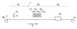
- Schematic diagram of an example of a recording device preferred for the present invention A conceptual diagram showing how ink is drawn into a pressure chamber during a maintenance operation of a circulation type inkjet head H.
- An example of an image pattern for a solid area An example of an image pattern where each solid area is rendered separately.
- the image forming method of the present invention is an image forming method having an ink coating step and a drying step, the ink containing at least one of pigment, inorganic particles, organic particles, and resin, water, and a water-soluble solvent, the ink coating step being a step of ejecting and coating at least a first ink and a second ink onto a substrate, at least one of the drying steps being a step of drying a coating film by irradiating microwaves, the complex dielectric constants of the first ink and the second ink at a drying rate of 95% being ⁇ ''1 and ⁇ ''2, respectively, satisfy the formula (1), and the drying rates of the first ink and the second ink when dried for 20 seconds at 80°C are D1 and D2, respectively, satisfy the formula (2).
- This feature is a technical feature common to or corresponding to each of the following embodiments (modes).
- the complex dielectric constant ⁇ ''1 of the first ink and the complex dielectric constant ⁇ ''2 of the second ink satisfy the formula (3) from the viewpoint of uniform drying control.
- the water-soluble solvent contains a humectant having a boiling point of 200°C or higher, the content of the humectant is within the range of 3 to 20% by mass relative to the first ink or the second ink, and the complex dielectric constant ⁇ '' at 25°C when the first ink or the second ink is irradiated with microwaves at a frequency of 2.45 GHz is within the range of 13 to 60.0.
- the content of the humectant is greater in the second ink than in the first ink.
- the ink contains a surfactant having a hydroxyl group.
- the ink contains a surfactant having a diol structure.
- the substrate is a resin film, it can be used effectively because it does not cause damage to the substrate.
- the contact angles of the first ink and the second ink with the water-repellent film are within a range of 60 to 80 at 25°C, from the viewpoint of improving the ejection stability of the ink and enabling rapid drying.
- the inkjet head is equipped with a nozzle circulation mechanism from the viewpoint of ejection stability of the first ink and the second ink.
- the inkjet head comprises at least one pressure chamber into which ink is injected, a pressure generating means for generating pressure fluctuations in the pressure chamber, a nozzle that communicates with the pressure chamber and serves as a flow path for ink that is ejected from the pressure chamber to the outside due to the pressure fluctuations in the pressure chamber, and a circulation path that communicates with the pressure chamber and discharges ink inside the nozzle and returns it to the injection path to the pressure chamber. It is preferable from the viewpoint of ejection stability of the first ink and the second ink that there are two or more circulation paths.
- the image forming system of the present invention is an image forming system having an ink coating means and a drying means, wherein the ink contains at least one or more of a pigment, inorganic particles, organic particles, and a resin, as well as water and a water-soluble solvent, the ink coating means is a means for ejecting and coating at least a first ink and a second ink onto a substrate, and at least one of the drying means is a means for drying a coating film by irradiating microwaves, and wherein when the complex dielectric constants of the first ink and the second ink at a drying rate of 95% are ⁇ ''1 and ⁇ ''2, respectively, the ⁇ ''1 and ⁇ '2 satisfy the above formula (1), and when the drying rates of the first ink and the second ink when dried at 80°C for 20 seconds are D1 and D2, respectively, the D1 and D2 satisfy the above formula (2), and the image forming system is preferably used in the image forming method of the present invention.
- the image forming method of the present invention is an image forming method having an ink coating step and a drying step, the ink containing at least one or more of a pigment, inorganic particles, organic particles, and a resin, as well as water and a water-soluble solvent, the ink coating step is a step of ejecting and coating at least a first ink and a second ink onto a substrate, at least one of the drying steps is a step of drying a coating film by irradiating with microwaves, and when the complex dielectric constants of the first ink and the second ink at a drying rate of 95% are ⁇ ''1 and ⁇ ''2, respectively, the ⁇ ''1 and ⁇ '2 satisfy the following formula (1): Equation (1): ⁇ ′′1 ⁇ ′′2 When the drying rates of the first ink and the second ink when dried at 80° C. for 20 seconds are D1 and D2, respectively, the D1 and D2 satisfy the following formula (2):
- drying is performed by irradiating microwaves that act directly on the ink and do not heat the substrate or atmosphere, making it possible to achieve both high-speed drying and ejectability.
- the drying properties can vary greatly depending on the differences in microwave absorption of each ink in the later stages of drying.
- the difference in microwave absorbency in the later stage of drying is taken into consideration, and the drying property of each ink is controlled according to its complex dielectric constant, thereby solving this problem and forming a high-quality image.
- the drying property of each ink is controlled according to its complex dielectric constant, thereby solving this problem and forming a high-quality image.
- Image forming method (1.1) Ink coating process The ink coating process according to the present invention is a process of ejecting and coating at least the first ink and the second ink onto a substrate. Note that the application of each ink in the first ink coating process and the second ink coating process is performed almost simultaneously.
- the ink according to the present invention varies in type depending on the purpose, with respect to the content ratio of pigment, resin, water, water-soluble solvent, and surfactant, and the like, and the complex dielectric constant at the later stage of drying, i.e., the complex dielectric constant of each ink at a drying rate of 95% in the present invention, varies.
- an ink (first ink) whose complex dielectric constant in the later stage of drying is relatively small compared to other inks is better at uniform drying control if the drying rate of the ink is relatively large.
- an ink (second ink) whose complex dielectric constant in the later stage of drying is relatively large compared to the first ink is better at uniform drying control if the drying rate of the ink is relatively small.
- the ⁇ ''1 and ⁇ ''2 satisfy the following formula (1): Equation (1): ⁇ ′′1 ⁇ ′′2
- the drying rates of the first ink and the second ink when dried at 80° C. for 20 seconds are D1 and D2, respectively, the D1 and D2 satisfy the following formula (2): D2 ⁇ D1 This allows for both fast drying of the ink and ejection stability, while eliminating damage to the substrate.
- a plurality of inks with different components, contents, etc. are used.
- one ink is designated as the first ink and the other ink is designated as the second ink.
- the first ink and the second ink are characterized in that their complex dielectric constants and drying rates in the later drying stage are relatively different, as described above.
- the complex dielectric constant and drying rate can be controlled, for example, by the amount of colorant contained in the ink or the amount of humectant contained in the water-soluble solvent.
- the first ink and the second ink may be applied not only to the same location on the substrate, but also to separate locations.
- an anionic dispersed pigment such as a self-dispersed pigment having an anionic group on the surface, a pigment dispersed by an anionic polymer dispersant, or a pigment dispersed by coating the surface with an anionic resin. It is also preferable to contain a pigment dispersant for dispersing the pigment. In particular, it is preferable to use a pigment dispersed by an anionic polymer dispersant, because it has excellent dispersibility and the pigment reacts appropriately with the precoat liquid to perform pinning.
- any conventionally known pigment can be used without any particular restrictions.
- inorganic pigments containing inorganic particles such as titanium oxide
- organic pigments containing organic particles such as insoluble pigments and lake pigments can be preferably used.
- the insoluble pigment is not particularly limited, but preferred examples include azo, azomethine, methine, diphenylmethane, triphenylmethane, quinacridone, anthraquinone, perylene, indigo, quinophthalone, isoindolinone, isoindoline, azine, oxazine, thiazine, dioxazine, thiazole, phthalocyanine, and diketopyrrolopyrrole.
- Organic pigments Specific examples of organic pigments that can be preferably used include the following pigments.
- pigments for magenta or red examples include C.I. Pigment Red 2, C.I. Pigment Red 3, C.I. Pigment Red 5, C.I. Pigment Red 6, C.I. Pigment Red 7, C.I. Pigment Red 15, C.I. Pigment Red 16, C.I. Pigment Red 48:1, C.I. Pigment Red 53:1, C.I. Pigment Red 57:1, C.I. Pigment Red 122, C.I. Pigment Red 123, C.I. Pigment Red 139, C.I. Pigment Red 144, C.I. Pigment Red 149, C.I. Pigment Red 166, C.I. Pigment Red 177, C.I. Pigment Red 178, C.I. Pigment Red 202, C.I. Pigment Red 222, C.I. Pigment Violet 19, etc.
- pigments for orange or yellow examples include C.I. Pigment Orange 31, C.I. Pigment Orange 43, C.I. Pigment Yellow 12, C.I. Pigment Yellow 13, C.I. Pigment Yellow 14, C.I. Pigment Yellow 15, C.I. Pigment Yellow 15:3, C.I. Pigment Yellow 17, C.I. Pigment Yellow 74, C.I. Pigment Yellow 93, C.I. Pigment Yellow 128, C.I. Pigment Yellow 94, C.I. Pigment Yellow 138, and C.I. Pigment Yellow 155.
- C.I. Pigment Yellow 155 is preferred in terms of the balance between color tone and light resistance.
- pigments for green or cyan examples include C.I. Pigment Blue 15, C.I. Pigment Blue 15:2, C.I. Pigment Blue 15:3, C.I. Pigment Blue 16, C.I. Pigment Blue 60, and C.I. Pigment Green 7.
- black pigments examples include C.I. Pigment Black 1, C.I. Pigment Black 6, and C.I. Pigment Black 7.
- inorganic pigments As the inorganic pigment, inorganic pigments of various colors can be used. In particular, it is preferable to use an inorganic pigment as a white pigment.
- the white pigment is not particularly limited as long as it is a pigment that causes the cured film formed by curing the ink containing the white pigment to exhibit a white color.
- white pigments examples include titanium oxide, zinc oxide, zinc sulfide, calcium carbonate, calcium silicate, barium sulfate, aluminum hydroxide, antimony oxide, zirconium oxide, silicas such as finely powdered silicic acid and synthetic silicates, talc, clay, etc.
- white metal oxides are preferred, and titanium oxide is more preferred. These may be used alone or in combination of two or more.
- Titanium oxide for which it is generally difficult to ensure ink ejection stability and adhesion, the present invention is particularly effective in preventing bleeding and increasing adhesion.
- Titanium oxide has three crystal forms: anatase, rutile, and brookite, but the most commonly used types can be broadly divided into anatase and rutile.
- rutile types are preferred, as they have a high refractive index and high hiding power. Specific examples include the TR series from Fuji Titanium Kogyo Co., Ltd., the JR series from Teika Corporation, and Typeque from Ishihara Sangyo Co., Ltd.
- the ink according to the present invention contains a pigment, it preferably contains a pigment dispersant for dispersing the pigment.
- the pigment dispersant for dispersing the pigment according to the present invention is not particularly limited, but is preferably a polymer dispersant having an anionic group, and one having a molecular weight in the range of 5,000 to 200,000 can be suitably used.
- polymeric dispersants include block copolymers and random copolymers having a structure derived from two or more monomers selected from styrene, styrene derivatives, vinylnaphthalene derivatives, acrylic acid, acrylic acid derivatives, maleic acid, maleic acid derivatives, itaconic acid, itaconic acid derivatives, fumaric acid, and fumaric acid derivatives, as well as salts thereof, polyoxyalkylene, and polyoxyalkylene alkyl ether.
- the polymeric dispersant preferably has an acryloyl group and is preferably neutralized with a neutralizing base before addition.
- the pigment is titanium oxide
- the titanium oxide is dispersed with a polymer dispersant having an acryloyl group.
- the neutralizing base is not particularly limited, but is preferably an organic base such as ammonia, monoethanolamine, diethanolamine, triethanolamine, or morpholine.
- the amount of polymer dispersant added is preferably within the range of 10 to 100% by mass relative to the pigment, and more preferably within the range of 10 to 40% by mass.
- the pigment has the form of a so-called capsule pigment, in which the pigment is coated with the polymer dispersant.
- a method for coating the pigment with the polymer dispersant various known methods can be used, but preferred examples include the phase inversion emulsification method, the acid precipitation method, and a method in which the pigment is dispersed in a polymerizable surfactant, a monomer is supplied thereto, and the pigment is coated while being polymerized.
- a particularly preferred method is to dissolve the water-insoluble resin in an organic solvent such as methyl ethyl ketone, partially or completely neutralize the acidic groups in the resin with a base, add the pigment and ion-exchanged water, disperse the pigment, remove the organic solvent, and add water as necessary to prepare the pigment.
- organic solvent such as methyl ethyl ketone
- the average particle size of the pigment in the dispersed state in the ink is preferably 50 nm or more and less than 200 nm. This improves the dispersion stability of the pigment and improves the storage stability of the ink.
- the particle size of the pigment can be measured using a commercially available particle size measuring device that uses a dynamic light scattering method, electrophoresis method, etc., but measurement using the dynamic light scattering method is simple and can measure the particle size range with high accuracy.
- the pigment can be dispersed using a dispersing machine together with a dispersant and other additives required for the desired purpose.
- a conventionally known ball mill, sand mill, line mill, high-pressure homogenizer, etc. can be used.
- dispersing the pigment with a sand mill is preferable because it produces a sharp particle size distribution.
- the material of the beads used for sand mill dispersion but from the viewpoint of preventing the generation of bead fragments and contamination of ionic components, it is preferable for the beads to be zirconia or zircon.
- the bead diameter to be within the range of 0.3 to 3 mm.
- the pigment content in the ink is not particularly limited, but for titanium oxide, the preferred range is 7 to 18% by mass, and for organic pigments, the preferred range is 0.5 to 7% by mass.
- the ink When the ink contains a resin, the ink can have a high fixability to a recording medium.
- the resin include vinyl chloride resin, (meth)acrylic resin, urethane resin, Examples of the resin include polyether resins and polyester resins. Among these, it is preferable that the ink contains a resin having ionic properties from the viewpoints of fixation property, film-forming property, and the like.
- the ionic resin When drying is performed using microwaves in the drying step described below, the ionic resin is directly heated by microwaves, improving film-forming properties and adhesion to the substrate.
- the ionic resin is preferably water-insoluble resin particles, and the glass transition temperature (Tg) of the resin particles is preferably within the range of 40 to 90°C.
- the glass transition temperature can be determined by reading the glass transition temperature (Tg) from the endothermic peak when the material is heated at a rate of 10°C/min in a temperature range of -30 to 200°C using a DSC (differential scanning calorimeter).
- Tg glass transition temperature
- the water-insoluble resin preferably used in the present invention is a water-insoluble resin that can accept ink and exhibits solubility or affinity for the ink.
- the "water-insoluble resin microparticles" used in the present invention are those that are inherently water-insoluble but have a form in which the resin disperses in an aqueous medium as microscopic microparticles, and are water-insoluble resins that are forcibly emulsified using an emulsifier or the like and dispersed in water, or water-insoluble resins that can be self-emulsified by introducing hydrophilic functional groups into the molecule to form a stable aqueous dispersion by themselves without using an emulsifier or dispersion stabilizer. These resins are usually used in an emulsified and dispersed state in water or a water/alcohol mixed solvent.
- water-insoluble refers to a resin that, when dried at 105°C for 2 hours and then dissolved in 100 g of water at 25°C, dissolves in an amount of 10 g or less, preferably 5 g or less, and more preferably 1 g or less.
- the dissolving amount is the amount dissolved when the salt-forming groups of the resin are 100% neutralized with acetic acid or sodium hydroxide depending on the type of resin.
- the resin having a glass transition temperature (Tg) in the range of 40 to 90°C is preferably any of acrylic resin, urethane resin, polyester, or a composite resin of urethane resin and acrylic resin.
- Tg glass transition temperature
- it is preferably acrylic resin, urethane resin, polyester, or a composite resin of urethane resin and acrylic resin, and the average particle size of these resin particles is preferably 200 nm or less. Furthermore, it is more preferable that the average particle size is in the range of 100 to 150 nm.
- the polyester, urethane resin, acrylic resin, or composite resin particles of urethane resin and acrylic resin are preferably anionic.
- the resin particles contained in the ink preferably have an acid structure, which makes it possible to disperse the particles in water even with a small amount of surfactant added, improving water resistance.
- This is called a self-emulsifying type, which means that the resin can be dispersed and stabilized in water with only molecular ionicity without using a surfactant or with only a small amount of surfactant used.
- the acid structure examples include acid groups such as a carboxy group (-COOH) and a sulfonic acid group (-SO 3 H).
- the acid structure may be present in a side chain of the resin or may be present at the terminal. It is particularly preferable for the ink according to the present invention to contain a water-dispersible polyester having a sulfonic acid group, which provides high adhesion to the substrate.
- the acid structures are partially or entirely neutralized, and by neutralizing the acid structures, the water dispersibility of the resin can be improved.
- a neutralizing agent for neutralizing the acid structures for example, organic amines are preferable, and it is preferable to use organic amines such as trimethylamine, triethylamine, tripropylamine, tributylamine, N-methyldiethanolamine, and triethanolamine.
- the ink according to the present invention preferably contains resin fine particles having an agglomeration property of 0.2 or less with a 0.15% by mass aqueous calcium acetate solution in the range of 3 to 15% by mass.
- the polyester having a polyester skeleton used as the water-insoluble resin particles can be obtained by using a polyhydric alcohol component and a polycarboxylic acid component such as a polycarboxylic acid, a polycarboxylic anhydride, or a polycarboxylic acid ester.
- the polyhydric alcohol component includes dihydric alcohols (diols), specifically alkylene glycols having 2 to 36 carbon atoms (ethylene glycol, 1,2-propylene glycol, 1,3-propylene glycol, 1,4-butylene glycol, 1,6-hexanediol, etc.), alkylene ether glycols having 4 to 36 carbon atoms (diethylene glycol, triethylene glycol, dipropylene glycol, polyethylene glycol, polypropylene glycol, polybutylene glycol, etc.), alicyclic diols having 6 to 36 carbon atoms (diols), alkylene ether glycols having 4 to 36 carbon atoms (diethylene glycol, triethylene glycol, dipropylene glycol, polyethylene glycol, polypropylene glycol, polybutylene glycol, etc.), and alicyclic diols having 6 to 36 carbon atoms (diols), alkylene ether glycols having 4 ...
- diols examples include 1,4-cyclohexanedimethanol, hydrogenated bisphenol A, etc., adducts of the alicyclic diols with alkylene oxides having 2 to 4 carbon atoms (ethylene oxide (hereinafter abbreviated as EO), propylene oxide (hereinafter abbreviated as PO), butylene oxide (hereinafter abbreviated as BO)) (number of moles added ranges from 1 to 30), and adducts of bisphenols (bisphenol A, bisphenol F, bisphenol S, etc.) with alkylene oxides having 2 to 4 carbon atoms (EO, PO, BO, etc.) (number of moles added ranges from 2 to 30). These may be used alone or in combination of two or more.
- EO ethylene oxide
- PO propylene oxide
- BO butylene oxide
- the polyvalent carboxylic acid component may be a divalent carboxylic acid (dicarboxylic acid), specifically an alkane dicarboxylic acid having 4 to 36 carbon atoms (succinic acid, apidic acid, sebacic acid, etc.), an alkenyl succinic acid (dodecenyl succinic acid, etc.), an alicyclic dicarboxylic acid having 4 to 36 carbon atoms (dimer acid (dimerized linoleic acid) etc.), an alkene dicarboxylic acid having 4 to 36 carbon atoms (maleic acid, fumaric acid, citraconic acid, mesaconic acid, etc.), or an aromatic dicarboxylic acid having 8 to 36 carbon atoms (phthalic acid, isophthalic acid, terephthalic acid or derivatives thereof, naphthalenedicarboxylic acid, etc.). These may be used alone or in combination of two or more.
- the polyester is preferably one having an anionic group in the molecule, and more preferably one containing a sulfonic acid group.
- a polyester containing sulfonic acid groups can be obtained by a known synthesis method, for example, a polycondensation reaction between a dicarboxylic acid having a sulfonic acid group and a diol. It can also be obtained by a polycondensation reaction between a dicarboxylic acid and a diol having a sulfonate salt.
- dicarboxylic acid components having a sulfonic acid group examples include 2-sulfoterephthalic acid, 5-sulfoisophthalic acid, 4-sulfonaphthaleneisophthalic acid-2,7-dicarboxylic acid, and 5-(4-sulfophenoxy)isophthalic acid, or alkali metal salts thereof.
- diols having a sulfonic acid group examples include 2-sulfo-1,4-butanediol, 2,5-dimethyl-3-sulfo-2,5-hexanediol, and alkali metal salts thereof.
- the number average molecular weight of the polyester is preferably in the range of 1,000 to 50,000, and more preferably in the range of 2,000 to 20,000.
- polyester commercially available products may be used.
- examples of commercially available water-dispersible polyesters having sulfonic acid groups include Vylonal MD-1100, MD-1200, MD-1245, MD-1480, MD-1500, and MD-2000 manufactured by Toyobo Co., Ltd., Plascoat Z-221, Z-446, Z-561, Z-880, and Z-3310 manufactured by GOO Chemical Co., Ltd., and PES Resin A-520, A-613D, A-615GE, A-640, A-645GH, A-647GEX, A-110F, and A-160P manufactured by Takamatsu Oil Co., Ltd.
- resins with a glass transition temperature (Tg) in the range of 40 to 90°C are particularly preferred, such as Vylonal MD-1100, MD-1200, MD-1245, MD-1500, and MD-2000 manufactured by Toyobo Co., Ltd., Plascoat Z-221, Z-446, and Z-561 manufactured by Goo Chemical Co., Ltd., and PES Resin A-520, A-613D, A-615GE, A-640, A-645GH, and A-647GEX manufactured by Takamatsu Oil Co., Ltd. These may be used alone or in combination of two or more types.
- Tg glass transition temperature
- the urethane resin used as the water-insoluble resin particles according to the present invention may be one having a hydrophilic group.
- the urethane resin is preferably an aqueous dispersion of a self-emulsifying urethane having a water-soluble functional group, i.e., a hydrophilic group, dispersed in its molecule, or an aqueous dispersion of a forced-emulsifying urethane emulsified under strong mechanical shearing force in combination with a surfactant.
- the urethane resin in the aqueous dispersion can be obtained by the reaction of a polyol with an organic polyisocyanate and a hydrophilic group-containing compound.
- polyester polyols include low molecular weight polyols such as ethylene glycol, diethylene glycol, triethylene glycol, 1,2- and 1,3-propylene glycol, neopentyl glycol, 1,3- and 1,4-butanediol, 3-methylpentanediol, hexamethylene glycol, 1,8-octanediol, 2-methyl-1,3-propanediol, bisphenol A, hydrogenated bisphenol A, trimethylolpropane, and cyclohexanedimethanol; and condensates with polycarboxylic acids such as succinic acid, glutaric acid, adipic acid, sebacic acid, phthalic acid, isophthalic acid, terephthalic acid, trimellitic acid, tetrahydrofuran acid, endomethinetetrahydrofuran acid, and hexahydrophthalic acid.
- polycarboxylic acids such as succinic acid, glutaric
- polyether polyols examples include polyethylene glycol, polypropylene glycol, polyethylene polytetramethylene glycol, polypropylene polytetramethylene glycol, and polytetramethylene glycol.
- polycarbonate polyols examples include those obtained by reacting carbonic acid derivatives such as diphenyl carbonate, dimethyl carbonate, or phosgene with diols.
- diols examples include ethylene glycol, diethylene glycol, triethylene glycol, 1,2- and 1,3-propylene glycol, neopentyl glycol, 1,3- and 1,4-butanediol, 3-methylpentanediol, hexamethylene glycol, 1,8-octanediol, 2-methyl-1,3-propanediol, bisphenol A, hydrogenated bisphenol A, trimethylolpropane, and cyclohexanedimethanol.
- organic polyisocyanates that can be used to prepare the aqueous dispersion of urethane resin include aromatic isocyanates such as tolylene diisocyanate (TDI), diphenylmethane diisocyanate (MDI), polymeric MDI, xylylene diisocyanate (XDI), and tetramethylxylylene diisocyanate (TMXDI); aliphatic isocyanates such as hexamethylene diisocyanate (HMDI); and alicyclic isocyanates such as isophorone diisocyanate (IPDI) and 4,4'-dicyclohexylmethane diisocyanate (hydrogenated MDI, H12MDI). These may be used alone or in combination of two or more types.
- aromatic isocyanates such as tolylene diisocyanate (TDI), diphenylmethane diisocyanate (MDI), polymeric MDI, xylylene diisocyanate (XD
- hydrophilic group-containing compounds that can be used to prepare aqueous dispersions of urethane resins include carboxylic acid-containing compounds such as 2,2-dimethylolpropionic acid, 2,2-dimethylolbutanoic acid, 2,2-dimethylolbutyric acid, 2,2-dimethylolvaleric acid, and glycine, as well as their sodium, potassium, and amine salt derivatives; and sulfonic acid-containing compounds such as taurine (i.e., aminoethylsulfonic acid) and ethoxypolyethylene glycol sulfonic acid, as well as their sodium, potassium, and amine salt derivatives.
- carboxylic acid-containing compounds such as 2,2-dimethylolpropionic acid, 2,2-dimethylolbutanoic acid, 2,2-dimethylolbutyric acid, 2,2-dimethylolvaleric acid, and glycine, as well as their sodium, potassium, and amine salt derivatives
- the urethane resin can be obtained by known methods.
- a urethane prepolymer can be obtained by mixing the above-mentioned polyol, organic polyisocyanate, and hydrophilic group-containing compound and reacting them at a temperature range of 30 to 130°C for 30 minutes to 50 hours.
- the urethane prepolymer can be polymerized by extending the chain with a chain extender to become a urethane resin with hydrophilic groups.
- the chain extender is preferably water and/or an amine compound.
- water or an amine compound as the chain extender, it is possible to react with free isocyanate in a short time and efficiently extend the isocyanate-terminated prepolymer.
- amine compounds as chain extenders include aliphatic polyamines such as ethylenediamine and triethylenediamine; aromatic polyamines such as metaxylenediamine and toluylenediamine; and polyhydrazino compounds such as hydrazine and adipic dihydrazide.
- the amine compounds may contain monovalent amines such as dibutylamine or methyl ethyl ketoxime as reaction terminators to the extent that they do not significantly inhibit polymerization.
- a solvent that is inert to the isocyanate and capable of dissolving the urethane prepolymer may be used.
- solvents include dioxane, methyl ethyl ketone, dimethylformamide, tetrahydrofuran, N-methyl-2-pyrrolidone, toluene, and propylene glycol monomethyl ether acetate. It is preferable that these hydrophilic organic solvents used in the reaction step are finally removed.
- a catalyst such as an amine catalyst (e.g., triethylamine, N-ethylmorpholine, triethyldiamine, etc.), a tin-based catalyst (e.g., dibutyltin dilaurate, dioctyltin dilaurate, tin octoate, etc.), or a titanium-based catalyst (e.g., tetrabutyl titanate, etc.) may be added to promote the reaction.
- an amine catalyst e.g., triethylamine, N-ethylmorpholine, triethyldiamine, etc.
- a tin-based catalyst e.g., dibutyltin dilaurate, dioctyltin dilaurate, tin octoate, etc.
- a titanium-based catalyst e.g., tetrabutyl titanate, etc.
- the number average molecular weight of the urethane resin is preferably in the range of 50,000 to 10,000,000.
- the urethane resin becomes less soluble in solvents, resulting in a coating film with excellent weather resistance and water resistance.
- commercially available urethane resins may be used.
- Tg glass transition temperature
- examples of commercially available urethane resins with a glass transition temperature (Tg) in the range of 40 to 90°C include Neorez R-967, R-600, and R-9671 manufactured by Kusumoto Chemicals, Evaphanol HA-560 manufactured by Nicca Chemical, and SF870 manufactured by Daiichi Kogyo Seiyaku.
- the number average molecular weight (Mn) is a value measured by gel permeation chromatography (GPC) and can be determined from a calibration curve made with a polystyrene standard sample using, for example, Shimadzu Corporation's "RID-6A” (column: Tosoh Corporation's “TSK-GEL", solvent: tetrahydrofuran (THF), column temperature: 40°C).
- the acrylic resin used as the water-insoluble resin particles can be obtained by using a copolymer with an acrylic acid ester component, a methacrylic acid ester component, or a styrene component.
- acrylic acid ester components and methacrylic acid ester components include methyl (meth)acrylate, ethyl (meth)acrylate, propyl (meth)acrylate, butyl (meth)acrylate, 2-hydroxyethyl (meth)acrylate, 2-hydroxypropyl (meth)acrylate, 4-hydroxybutyl (meth)acrylate, cyclohexyl (meth)acrylate, tetrahydrofurfuryl (meth)acrylate, isobornyl (meth)acrylate, benzyl (meth)acrylate, and methyl (meth)acrylate.
- styrene components include styrene, 4-methylstyrene, 4-hydroxystyrene, 4-acetoxystyrene, 4-acetylstyrene, and styrenesulfonic acid. These components may be used alone or in combination of two or more types.
- the number average molecular weight (Mn) of the acrylic resin is preferably within the range of 1000 to 50,000, and more preferably within the range of 2000 to 20,000.
- the number average molecular weight (Mn) of the acrylic resin is 1000 or more, the cohesive force of the coating film is strong and the adhesion is improved, and when it is 50,000 or less, the solubility in organic solvents is good, and the particle size of the emulsion dispersion is promoted to be miniaturized.
- the acrylic resin may be a commercially available product.
- commercially available acrylic resins with a glass transition temperature (Tg) in the range of 40 to 90°C include acrylic emulsions such as Mowinyl 6899D, 6969D, and 6800 manufactured by Japan Coating Resins, and TOCRYL W-7146, W-7147, W-7148, W-7149, and W-7150 manufactured by Toyochem.
- the number average molecular weight (Mn) is a value measured by gel permeation chromatography (GPC) and can be determined from a calibration curve made with a polystyrene standard sample using, for example, Shimadzu Corporation's "RID-6A” (column: Tosoh Corporation's “TSK-GEL", solvent: tetrahydrofuran (THF), column temperature: 40°C).
- the composite resin particles that can be contained in the ink are preferably composite resin particles in which an acrylic resin is emulsified in a urethane resin, that is, composite resin particles having an inner layer made of an acrylic resin and a surface layer made of a urethane resin.
- the urethane resin is present at the interface between the acrylic resin as water-insoluble resin particles and the water as a continuous phase, and functions as a water-insoluble resin particle layer that is different from the resin that protects the water-insoluble resin particles.
- the mass ratio (U/A) of the urethane resin (U) to the acrylic resin (A) is preferably within the range of (40/60) to (95/5).
- the proportion of the urethane resin (U) is within this range, compatibility with the dispersant is improved, and solvent resistance is also improved.
- the content of the acrylic resin (A) is within the above range, the adhesion to the acrylic film is excellent.
- the mass ratio (U/A) of the urethane resin (U) to the acrylic resin (A) is preferably within the range of (40/60) to (80/20).
- the total resin concentration of the acrylic resin and urethane resin in the composite resin microparticles is not particularly limited, but is preferably 5.0% by mass or more, and more preferably within the range of 10.0 to 70.0% by mass. If the resin concentration is within this range, the ink will have good fixability to the recording medium.
- a surfactant that acts as an emulsifier can be used together with the urethane resin.
- an emulsifier by adding an emulsifier, the storage stability of the composite resin microparticles can be improved.
- Anionic surfactants and nonionic surfactants can be used as the emulsifier.
- the average particle size of the composite resin microparticles is not particularly limited, but is preferably within the range of 10 to 500 nm, more preferably within the range of 10 to 300 nm, and even more preferably within the range of 10 to 200 nm.
- the average particle size can be measured using a commercially available particle size measuring device that uses a dynamic light scattering method, electrophoresis method, etc., but measurement using the dynamic light scattering method is simple and can measure the particle size range with high accuracy.
- the inorganic particles contained in the ink according to the present invention are used as an inorganic pigment by being contained in a pigment, for example.
- pigments containing inorganic particles include light calcium carbonate, heavy calcium carbonate, magnesium carbonate, kaolin, clay, talc, calcium sulfate
- white inorganic pigments include barium sulfate, titanium dioxide, zinc oxide, zinc hydroxide, zinc sulfide, zinc carbonate, hydrotalcite, aluminum silicate, diatomaceous earth, calcium silicate, magnesium silicate, synthetic amorphous silica, colloidal silica, alumina, colloidal alumina, pseudoboehmite, aluminum hydroxide, lithopone, zeolite, and magnesium hydroxide.
- the inorganic particles contained in inks include titanium oxide, but it is difficult to ensure ink ejection stability and adhesion with titanium oxide, and due to its high complex dielectric constant, it is significantly affected by the heating effect of microwaves in the drying process described below.
- the heating effect of microwaves can be appropriately controlled, thereby compensating for the disadvantages of titanium oxide as described above.
- Organic particles contained in the ink according to the present invention are used as an organic pigment, for example, by being contained in a pigment.
- the organic particles according to the present invention are water-insoluble organic particles that dissolve or swell in a water-soluble organic solvent having a boiling point of 120° C. or higher.
- the material thereof is selected from conventionally known materials, such as polyvinyl chloride, polyvinylidene chloride, polyacrylate, polymethacrylate, elastomer, ethylene-vinyl acetate copolymer, styrene-(meth)acrylic copolymer, polyester, polyvinyl ether, polyvinyl acetal, polyamide, polyurethane, polyolefin, SBR, NBR, polytetrafluoroethylene, chloroprene, protein, polysaccharide, rosin ester, shellac resin, etc.
- conventionally known materials such as polyvinyl chloride, polyvinylidene chloride, polyacrylate, polymethacrylate, elastomer, ethylene-vinyl acetate copolymer, styrene-(meth)acrylic copolymer, polyester, polyvinyl ether, polyvinyl acetal, polyamide, polyurethane, polyolefin, S
- Particularly preferred materials for the organic particles are polyvinyl acetal resins, polyurethane resins, rosin ester resins, (meth)acrylate resins, SBR, etc., and resins consisting of two or more types of monomers obtained by modification or copolymerization are also preferably used.
- resins to which a specific modifying group has been added or from which a leaving group has been removed may also be used.
- Two or more types of materials may be mixed to form organic particles, and two or more types of organic particles may also be mixed and used.
- dissolution refers to the organic particles and the water-soluble organic solvent in the ink forming a single phase in equilibrium
- swelling refers to the organic particles absorbing the water-soluble organic solvent and increasing in volume
- the organic particles according to the present invention must be insoluble in water so that they do not dissolve during inkjet recording. However, they are permitted to absorb water to the extent that it does not impede the ink absorption speed. They may absorb up to 20% by mass of water based on the mass of the organic particles.
- a crosslinking agent may be used for the organic particles according to the present invention to the extent that it does not impede dissolution or swelling in water-soluble organic solvents.
- the crosslinking agent may be any of the conventionally known crosslinking agents, whether organic or inorganic.
- the organic particles themselves are hydrophilic but not water-soluble, it is preferable that the content be adjusted to a range of 10% by mass or more and less than 50% by mass.
- Inkjet recording paper is usually used at room temperature, but the storage conditions before use are not necessarily room temperature. In particular, the temperature inside a closed car during the summer can become very high, so it is desirable to be able to use the paper without problems even after it has been exposed to such an environment. For this reason, the glass transition temperature (Tg) of the organic particles in the above-described embodiment must be 70°C or higher, preferably 80°C or higher, and more preferably within the range of 90 to 120°C.
- the glass transition temperature (Tg) of the organic particles is less than 70°C, the organic particles are more likely to fuse together when heated, which can result in the voids on the surface of the recording paper shrinking or decreasing, and the ink absorption rate being reduced.
- the water according to the present invention constitutes an aqueous solution together with a surfactant, and any known water can be used as the water, without any particular limitation.
- water-soluble solvent examples include ethanol (boiling point: 78° C.), ethylene glycol (boiling point: 198° C.), propylene glycol (boiling point: 188° C.), diethylene glycol monobutyl ether (boiling point: 230° C.), 1,2-hexanediol (boiling point: 170° C.), dipropylene glycol (boiling point: 230° C.), glycerin (boiling point: 290° C.), 1,3-propanediol (boiling point: 215° C.), and 1,2-pentanediol (boiling point: 242° C.).
- the water-soluble solvent may be a single solvent or multiple solvents. When multiple solvents are used, it is preferable that one of the solvents has a boiling point of 150° C. or higher. This can suppress the ink from drying in the vicinity of the nozzle of the inkjet head, and can prevent solid matter from precipitating and clogging the nozzle, etc., resulting in poor ejection performance. It is more preferable that one of the water-soluble solvents is a humectant.
- the "humectant” according to the present invention refers to a solvent that has high microwave or high-frequency wave absorption and a high boiling point.
- the humectant When contained in the water-soluble solvent contained in the ink according to the present invention, the humectant has the effect of suppressing evaporation of water in the ink composition and preventing aggregation of solids such as pigments and polymer particles in the ink.
- the humectant also plays a role in slowing down the drying speed of the ink.
- moisturizer When a moisturizer with a high boiling point is contained in a water-soluble solvent, the moisturizer is not likely to evaporate, but the water-soluble solvent itself can be directly heated by using microwaves.
- Moisturizers are solvents that tend to dry easily when irradiated with microwaves, but are difficult to dry under normal atmospheres, making them ideal for controlling uniform drying.
- the moisturizing agent preferably has a boiling point of 200°C or higher.
- a solvent with a high boiling point and that is easily heated directly by microwaves or high-frequency dielectric waves (high complex dielectric constant) and a boiling point of 200°C or higher the ink can be made moisturizing, which can stabilize ejection. This can then be dried quickly by using microwaves and high-frequency dielectrics, achieving both high-speed drying and stable ejection.
- the ink when the ink is ejected from the inkjet head, it is possible to prevent the ink from drying out in the nozzles of the inkjet head, thereby improving the ejection stability of the ink.
- the content of the humectant is within the range of 3 to 20% by mass relative to the first ink or the second ink, and that the complex dielectric constant ⁇ '' at 25°C when the first ink or the second ink is irradiated with microwaves at a frequency of 2.45 GHz is within the range of 13 to 60.0.
- the content of the humectant is greater in the second ink (ink having a relatively high complex dielectric constant) than in the first ink (ink having a relatively low complex dielectric constant).
- moisturizing agents examples include dipropylene glycol (boiling point: 230°C), 1,4-butanediol (boiling point: 230), glycerin (boiling point: 290°C), 1,2-pentanediol (boiling point: 242°C), 1,5-pentanediol (boiling point: 242°C), and 1,3-propanediol (boiling point: 215°C).
- the ink according to the present invention contains a surfactant, which makes it possible to improve the ejection stability of the ink and to control the spread (dot diameter) of ink droplets that land on a recording medium.
- the surfactant is not particularly limited, but if the ink components contain an anionic compound, the ionicity of the surfactant may be anionic, nonionic (also called “nonionic"), or amphoteric, and as an amphoteric ionic surfactant, a betaine type is preferable.
- an anionic surfactant contains an alkaline component, the resin particles contained as the fixing resin tend to aggregate, decreasing the fixing property, so it is preferable that the surfactant is nonionic.
- the surfactant is preferably a fluorine-based or silicone-based surfactant that has a high static surface tension reducing ability, an anionic surfactant such as dioctyl sulfosuccinate that has a high dynamic surface tension reducing ability, or a nonionic surfactant such as a relatively low molecular weight polyoxyethylene alkyl ether, polyoxyethylene alkyl phenyl ether, acetylene glycols, Pluronic (registered trademark) type surfactant, or a sorbitan derivative.
- a surfactant that has a high static surface tension reducing ability and a surfactant that has a high dynamic surface tension reducing ability may be used in combination.
- TEGOWET-KL245 polyether-modified siloxane copolymer; manufactured by Evonik
- the ink contains a surfactant having a hydroxyl group, as this appropriately controls the surface tension and viscosity of the ink according to the present invention and improves the coatability of the ink, and it is even more preferable that the surfactant has a diol structure.
- the surfactant that remains when the ink dries has high microwave absorption capacity, which results in the unexpected effect of fast drying and improved film uniformity.
- the complex dielectric constant in the later stages of drying is high. And this effect is further enhanced when the surfactant has a diol structure.
- the ink according to the present invention may contain various known additives depending on the purpose such as ejection stability, compatibility with print heads or ink cartridges, storage stability, image storage stability, etc.
- the ink according to the present invention may be appropriately blended with a pH adjuster, a crosslinking agent, an antifungal agent, a bactericide, etc., and other components.
- complex dielectric constant means a numerical value indicating the response (degree of dielectric polarization) of a molecule when an external electric field is applied, which is specific to a substance and is a dimensionless quantity based on the dielectric constant ⁇ 0 (electric constant) in a vacuum.
- the complex dielectric constant of the first ink and the second ink according to the present invention is less than the complex dielectric constant of the precoat liquid described below, when drying is performed with microwaves in the drying process described below, the precoat liquid will be more strongly affected by the heating effect of microwaves than the first ink and the second ink.
- the precoat liquid mixes with the first ink and the second ink, improving the drying properties of each ink, and quick drying properties can be imparted to areas where increased drying properties are desired in the image forming method of the present invention.
- This allows for uniform drying control, and also allows for the formation of uniform dots without graininess, resulting in the formation of images with excellent gloss and color gamut.
- applying the precoat liquid to areas where the first ink and the second ink are not applied is preferable, as it allows the effect of microwaves to be controlled in accordance with the application areas of the first ink and the second ink.
- the present invention is characterized in that when the complex dielectric constants of the first ink and the second ink at a drying rate of 95% are ⁇ ''1 and ⁇ ''2, respectively, these ⁇ ''1 and ⁇ ''2 satisfy the following formula (1).
- the complex dielectric constant ⁇ ''1 of the first ink and the complex dielectric constant ⁇ ''2 of the second ink to satisfy the relationship of the following formula (3) in order to keep the heat generation effect within an appropriate range and control the drying properties uniformly.
- the complex dielectric constant is measured using a complex dielectric constant measuring device (for example, Toyo Corporation's Material Impedance Analyzer MIA-5M (SH2-Z type 4-terminal sample holder)).
- a complex dielectric constant measuring device for example, Toyo Corporation's Material Impedance Analyzer MIA-5M (SH2-Z type 4-terminal sample holder)
- the physical properties of the ink of the present invention are not particularly limited and can be appropriately selected depending on the purpose. For example, it is preferable that the viscosity, surface tension, pH, etc. are within the following ranges.
- the ink viscosity at 25°C is preferably in the range of 5 to 30 mPa ⁇ s, and more preferably in the range of 5 to 25 mPa ⁇ s, from the viewpoint of improving print density and character quality, and obtaining good ejection stability from the nozzles of the inkjet head.
- the viscosity can be measured, for example, using a rotational viscometer "RE-80L” manufactured by Toki Sangyo Co., Ltd., under the following measurement conditions: 25°C, standard cone rotor (1°34' x R24), sample liquid volume 1.2 mL, rotation speed 50 rpm, 3 minutes.
- the surface tension of the ink is preferably within the range of 1 to 55 mN/m at 25°C, more preferably 1 to 40 mN/m or less, and even more preferably 1 to 35 mN/m, in order to ensure that the ink levels well on the recording medium and to shorten the drying time of the ink.
- Surface tension can be measured by the Wilhelmy method using a surface tensiometer such as the "CBVP-Z" manufactured by Kyowa Interface Science Co., Ltd.
- the pH value of the ink is preferably within the range of 3 to 9, and more preferably within the range of 6 to 9.
- the method for applying the first ink and the second ink according to the present invention onto a substrate, or onto a substrate onto which a precoat liquid has been applied is not particularly limited, as with the precoat liquid described above. However, application by an inkjet method is preferable from the viewpoint of controlling the uniformity and concentration of the ink.
- the second ink When the second ink is applied after the first ink, it is preferable to apply the second ink within 0.1 to 5 seconds after the application of the first ink. By applying the second ink immediately after the application of the first ink, diffusion of the first ink and the second ink occurs, improving wettability.
- the drying process according to the present invention includes a process of drying the first ink and the second ink (hereinafter, also simply referred to as the "ink drying process").
- the ink drying process the first ink and the second ink applied on the substrate, and, if necessary, a precoat liquid, etc. are irradiated with microwaves to perform uniform drying control.
- Uniform drying control here refers to imparting quick-drying properties to a specific area to be dried, while controlling the drying of areas other than that area and other areas uniformly.
- the first ink and the second ink applied to the substrate are dried by being irradiated with microwaves in an ink drying process to form a coating film.
- coating film includes not only one formed by the first ink and the second ink, but also one formed by the precoat liquid, the first ink, and the second ink.
- the thickness of the coating film obtained in the above manner is preferably within the range of 0.3 to 3.0 ⁇ m, and more preferably within the range of 0.3 to 2.0 ⁇ m. If the thickness of the coating film is 0.3 ⁇ m or more, the adhesion and abrasion resistance of the image are easily improved. Furthermore, if the thickness of the coating film is 3.0 ⁇ m or less, the deformation stress applied to the ink layer can be reduced, so the adhesion of the image is less likely to be impaired.
- At least one of the drying steps according to the present invention is a step of drying the coating film by irradiating microwaves.
- microwaves are used to dry the ink.
- Microwaves are highly directional and act directly on materials with a high complex dielectric constant, resulting in high drying efficiency and no damage to plastic substrates, etc.
- the drying control since there is no longer a need to add atmospheric conditions (conditions due to wind, temperature, etc.) to the drying control, it is possible to prevent the nozzle from drying out during inkjet coating, and it is possible to dry immediately after printing without worrying about nozzle drying. Furthermore, if the precoat liquid contains metal salts, etc., the coagulation effect is enhanced, improving durability and fastness.
- the above-mentioned “coating film” includes the liquid state having fluidity such as wet spreadability or permeability immediately after the precoat liquid is applied to the area outside the ink application area on the substrate, immediately after the ink is applied to the substrate, or immediately after the precoat liquid and the ink are mixed on the substrate, as well as the state thereafter (state after drying).
- liquid state having fluidity refers to a state in which a liquid (including semi-solid liquids in the present invention) spreads or spreads on a substrate or coating film, or moves so as to penetrate the substrate or coating film.
- Microwave irradiation tends to generate Joule heat and generate heat when the complex dielectric constant is high.
- the heat generation effect caused by microwave irradiation can be uniformly controlled by controlling the complex dielectric constant of the first ink and the second ink, and the properties and combinations of the pigment, resin, water, water-soluble solvent, surfactant, etc. to control the drying speed.
- a microwave generator manufactured by Shimada Rika Kogyo Co., Ltd. can be used, but a commercially available microwave dryer such as a batch microwave dryer manufactured by Yamamoto Vinita Co., Ltd. may also be used.
- the present invention may also be carried out using a non-contact heating drying device such as a drying oven or a hot air blower, or a contact heating drying device such as a hot plate or a heated roller. Similar effects can also be expected when drying is carried out using high frequency (13 to 50 MHz) radiation instead of microwaves.
- the heating temperature is preferably within the range of 60 to 120°C, and the heating time is adjusted appropriately according to the type of substrate, the amount of the precoat liquid applied, and the amount of the first ink and the second ink applied.
- the drying temperature can be obtained by measuring one of the following throughout the entire drying period of the precoat liquid and ink: (a) when a non-contact heating drying device such as a drying oven or hot air blower is used, the ambient temperature such as the oven temperature or hot air temperature; (b) when a contact heating drying device such as a hot plate or hot roller is used, the temperature of the contact heating part; or (c) the surface temperature of the surface to be dried. It is more preferable to measure the surface temperature of the surface to be dried (c).
- the solvent components of the precoat liquid and the ink are removed, and at the same time, in the case of metal substrates in particular, the polyvalent metal salt is dried and thermally decomposed at a temperature equal to or higher than the thermal decomposition temperature.
- the image has good abrasion resistance and adhesion to the substrate.
- Air drying In the drying step using microwave irradiation, it is preferable from the viewpoint of controlling drying properties to dry the coated materials of the first ink and the second ink by applying air at a temperature of 100° C. or less.
- the air speed is preferably 5 to 40 m/s.
- the complex dielectric constant of the second ink according to the present invention is significantly higher than that of the first ink, and therefore the second ink has higher drying properties and dries quickly.
- the drying rate (D1) of the first ink larger than the drying rate (D2) of the second ink, the drying properties of the first ink and the second ink are balanced, making it possible to control the drying properties uniformly.
- the drying rate when the first ink and the second ink are dried at 80°C for 20 seconds is measured and calculated as follows.
- Ink is applied with a wire bar onto a PET substrate cut to 10 cm x 10 cm to obtain a sample for measuring the drying rate.
- the mass of the sample is then immediately measured with an electronic balance, and this measurement is the sample's "mass before drying.”
- the sample is then dried in a hot air oven at 80°C for 20 seconds, after which the mass is measured again with the electronic balance, and this measurement is the sample's "mass after drying.”
- the total mass of the ink is calculated from the amount of ink applied to a PET substrate cut to 10 cm x 10 cm.
- the total mass of the solvent in the ink is then calculated from the ratio of the solvent to the total ink.
- Drying rate [%] (mass before drying - mass after drying) / total mass of solvent in ink x 100
- Step 1 It is preferable to have a step of applying a precoat liquid before the step of applying the ink and the step of drying the ink.
- the precoat liquid according to the present invention plays a role in fixing (pinning) the first ink and the second ink on the recording medium.
- the precoat liquid can be applied before the first ink and the second ink are applied onto the substrate, or it can be applied after the first ink and the second ink are applied onto the substrate.
- drying property of the applied portion of the precoat liquid can be improved. Drying property can also be controlled by adjusting the amount of precoat depending on the difference in the complex dielectric constant of the first ink and the second ink.
- a precoat liquid is usually used for the purpose and perspective of aggregating the ink appropriately, suppressing uneven aggregation, and improving the pinning ability of the ink.
- the precoat liquid plays a role in fixing (pinning) the ink onto the recording medium
- the precoat liquid is applied to the substrate before applying the ink, and after the precoat liquid dries, it mixes with the ink on the substrate to form an ink aggregation layer.
- the above-mentioned precoat liquid does not need to be used, but by utilizing the aggregation effect caused by the reaction between the precoat liquid and the ink and by providing quick drying properties, the use of the precoat liquid makes it possible to control the drying properties more uniformly.
- the use of the precoat liquid makes it possible to control the drying properties more uniformly.
- by applying a precoat liquid with a high complex dielectric constant to the desired location it becomes possible to control the drying properties uniformly.
- the precoat liquid according to the present invention contains, for example, a resin, a metal salt, an organic acid, an inorganic acid, a solvent, a surfactant, and the like.
- a metal salt, a resin (especially a cationic resin), or an organic acid reacts with the ink when mixed with it to thicken it and has the effect of acting as a flocculant, so that a high-quality image can be formed even when the image is formed on, for example, a non-absorbent substrate.
- these can be contained alone or in combination of two or more kinds.
- the complex dielectric constant of the precoat liquid can be changed by combining these materials, making it possible to control the heating effect of the microwaves.
- the drying pinning effect of the microwaves is superimposed, resulting in the formation of an image with less graininess, higher gloss, and a higher color gamut.
- the complex dielectric constant of the precoat liquid is equal to or greater than the complex dielectric constants of the first ink and the second ink, which increases the drying properties of the mixed coating of the precoat liquid and the ink, forms uniform dots without graininess, and is preferable in terms of gloss and color gamut.
- the precoat liquid according to the present invention contains, as a resin, for example, a vinyl chloride resin, a (meth)acrylic resin, a urethane resin, a polyether resin, a polyester resin, etc. Among them, it is preferable that the precoat liquid contains a resin having ionic properties from the viewpoint of fixing property, film-forming property, etc.
- the resin contained in the precoat liquid according to the present invention may be water-soluble. Since pigments are usually anionic components, it is preferable that the resin contained in the precoat liquid is a cationic resin, which mixes with the ink to form an ink aggregation layer.
- the precoat liquid according to the present invention preferably contains an inorganic or organic polyvalent metal salt as the metal salt.
- the precoat liquid contains the polyvalent metal salt, anionic components in the ink mixed with the precoat liquid on the substrate are coagulated by salting out.
- the polyvalent metal salt may be a salt of a metal having a valence of divalent or higher.
- the type of metal (cation) constituting the polyvalent metal salt is not particularly limited, and examples thereof include divalent metal ions such as Ca2 + , Cu2 + , Ni2 + , Mg2 + , Zn2 + , and Ba2 + , trivalent metal ions such as Al3 + , Fe3 + , Cr3 + , and Y3 +, and tetravalent metal ions such as Zr4 +, etc.
- the type of salt constituting the polyvalent metal salt is not particularly limited, but known salts such as carbonates, sulfates, nitrates, hydrochlorides, organic acid salts, borates, and phosphates can be used.
- calcium or magnesium salts of carboxylic acids such as calcium chloride, magnesium chloride, calcium nitrate, magnesium nitrate, magnesium acetate, calcium acetate, magnesium lactate, and calcium pantothenate are preferred.
- Metal salts other than polyvalent metal salts include monovalent metal salts such as sodium salts and potassium salts, for example sodium sulfate and potassium sulfate.
- Organic Acid is capable of aggregating pigments that may be contained in the ink.
- the precoat liquid contains an organic acid as an aggregating agent, it is possible to aggregate anionic components in the ink by changing the pH.
- organic acid monovalent carboxylic acids are preferred from the viewpoint of not weakening the cohesive force of the polyvalent metal salt, and examples thereof include formic acid, malonic acid, acetic acid, propionic acid, isobutyric acid, and benzoic acid.
- organic acids include formic acid, malonic acid, acetic acid, propionic acid, and benzoic acid.
- inorganic Acid examples include inorganic acids, such as sulfuric acid, hydrochloric acid, nitric acid, and phosphoric acid. These may be used alone or in combination of two or more kinds.
- solvent In the precoat liquid according to the present invention, both water-soluble and non-water-soluble solvents can be used as the solvent.
- the precoat liquid according to the present invention may contain, as a solvent, a water-soluble solvent having a boiling point in the range of 150 to 250° C. If such a water-soluble solvent with a high boiling point is contained, the precoat liquid becomes difficult to evaporate and the drying property is reduced, which is preferable from the viewpoint of uniform drying property control.
- the image forming method of the present invention by applying a precoat liquid containing a water-soluble solvent with a high boiling point as described above to an area where it is desired to reduce the drying speed, it is possible to slow down the drying speed of a specific area, which is suitable for controlling the drying speed uniformly.
- water-soluble solvent examples include alcohols, polyhydric alcohols, amines, amides, glycol ethers, and 1,2-alkanediols having 4 or more carbon atoms.
- Water-soluble solvents with boiling points in the range of 180 to 300°C include ethylene glycol, propylene glycol, dipropylene glycol, 1,3-propanediol, glycerin, etc.
- the precoat liquid according to the present invention may contain, as a solvent, a non-water-soluble solvent other than the water-soluble solvent having a boiling point in the range of 150 to 250° C.
- a non-water-soluble solvent include trimethylolpropane, triethylene glycol, and tetraethylene glycol.
- the precoat liquid according to the present invention preferably contains a surfactant.
- the surfactant is not particularly limited, but is preferably at least one selected from the group consisting of polysiloxane-based surfactants and acetylene glycol-based surfactants.
- polysiloxane surfactants are more preferred because they have a higher solubility in the precoat liquid, making it even less likely for foreign matter to be generated in the precoat liquid.
- the polysiloxane surfactant is not particularly limited, but examples thereof include TEGOWET-KL245 (polyether-modified siloxane copolymer; manufactured by Evonik Corporation), BYK-3 BYK-47 (manufactured by BYK-Chemie Corporation), BYK-348 (manufactured by BYK-Chemie Corporation), BYK-349 (manufactured by BYK-Chemie Corporation), BYK-3550 (manufactured by BYK-Chemie Corporation), BYK-UV3510 (manufactured by BYK-Chemie Corporation), and the like can be used.
- TEGOWET-KL245 polyether-modified siloxane copolymer; manufactured by Evonik Corporation
- BYK-3 BYK-47 manufactured by BYK-Chemie Corporation
- BYK-348 manufactured by BYK-Chemie Corporation
- BYK-349 manufactured by BYK-Chemie
- the acetylene glycol surfactant is not particularly limited, but is preferably at least one selected from, for example, 2,4,7,9-tetramethyl-5-decyne-4,7-diol, alkylene oxide adducts of 2,4,7,9-tetramethyl-5-decyne-4,7-diol, and alkylene oxide adducts of 2,4-dimethyl-5-decyne-4-ol and alkylene oxide adducts of 2,4-dimethyl-5-decyne-4-ol.
- E series including the Olfin 104 series and Olfin E1010 (manufactured by Air Products Japan, Inc.), Olfin PD-002W, Surfynol 465, and Surfynol 61 (manufactured by Nissin Chemical Industry Co., Ltd.).
- the content of the above surfactant is preferably within the range of 0.1 to 10% by mass relative to the total mass of the reaction liquid (100% by mass).
- the precoat liquid according to the present invention may contain water, a crosslinking agent, a fungicide, a bactericide and other components as appropriate within the range that does not impair the effects of the present invention.
- It can also contain various known additives such as various cationic or nonionic surfactants, fluorescent brighteners described in JP-A-59-42993, JP-A-59-52689, JP-A-62-280069, JP-A-61-242871, and JP-A-4-219266, antifoaming agents, lubricants such as diethylene glycol, preservatives, thickeners, antistatic agents, etc.
- the complex dielectric constant of the precoat liquid according to the present invention is equal to or greater than the complex dielectric constants of the first ink and the second ink, in order to improve the drying property of the mixed coating film of the precoat liquid, the first ink, and the second ink, form uniform dots without graininess, and improve gloss and color gamut. Details of the complex dielectric constant are as explained in the section on the physical properties of the inks.
- the physical properties of the precoat liquid according to the present invention are not particularly limited and can be appropriately selected depending on the purpose.
- the viscosity of the precoat liquid at 25° C. is such that good ejection stability from the nozzles of the inkjet head can be obtained. From this viewpoint, it is preferable that the viscosity is within the range of 5 to 30 mPa ⁇ s.
- the surface tension of the precoat liquid is preferably within the range of 1 to 55 mN/m at 25°C, in order to ensure that the ink is properly leveled on the recording medium and the drying time of the ink is shortened.
- the method of applying the precoat liquid onto the substrate is not particularly limited, but preferred examples include an inkjet method, a roller coating method, a curtain coating method, and a spray coating method.
- the precoat liquid by an inkjet method from the viewpoint of freely controlling the amount and range of application of the precoat liquid.
- a printer equipped with an inkjet head loaded with the precoat liquid can be used.
- inks with low complex dielectric constants that are close to insulating include yellow ink (Y), magenta ink (M) and cyan ink (C), while examples of inks with high complex dielectric constants include black ink (K) and white ink (W).
- inks that contain highly conductive metal oxides or metals also have high complex dielectric constants.
- the ink with a high complex dielectric constant is not dried excessively compared to the ink with a low complex dielectric constant close to insulating properties, and uniform drying control can be performed, resulting in high-quality printed matter.
- the substrate (recording medium) applicable to the present invention is not particularly limited, and examples thereof include substrates that are non-ink absorbing or have low ink absorbing properties.
- microwaves are used to dry the first ink and the second ink, so that substrates that do not absorb microwaves do not generate heat. Therefore, damage to the substrate can be suppressed.
- first ink and the second ink are dried using microwaves, there is no need to dry the first ink and the second ink depending on atmospheric conditions (conditions due to wind, temperature, etc.), and this makes it possible to prevent the nozzles from drying out during inkjet coating. Therefore, even if the substrate is a resin film that is easily affected by heat, the substrate is not damaged and ink ejection stability can be ensured.
- non-ink-absorbent substrates include resin films that have not been surface-treated for inkjet printing (i.e., no ink-absorbing layer is formed), substrates such as paper that are coated with resin, or substrates with a resin film adhered thereto, etc.
- resin films include polyesters such as polyethylene terephthalate (PET) and polyethylene naphthalate (PEN), polyethylene, polypropylene, cellophane, cellulose esters or derivatives thereof such as cellulose diacetate, cellulose triacetate (TAC), cellulose acetate butyrate, cellulose acetate propionate (CAP), cellulose acetate phthalate, and cellulose nitrate, polyvinylidene chloride, polyvinyl alcohol, polyethylene vinyl alcohol, syndiotactic polystyrene, polycarbonate, norbornene resin, polymethylpentene, polyether ketone, polyimide, polyether sulfone (PES), polyphenylene sulfide, polysulfones, polyetherimide, polyether ketone imide, polyamide, fluororesin, nylon, polymethyl methacrylate, acrylics or polyarylates, and cycloolefin resins such as Arton (trade name, manufactured by JSR Corporation
- low ink absorbent substrates examples include printing papers such as art paper, coated paper, and matte paper.
- non-ink absorbent and low ink absorbent substrates refers to "recording media having a water absorption of 10 mL/m2 or less from the start of contact to 30 msec 1/2 in the Bristow method.”
- the Bristow method is the most widely used method for measuring the amount of liquid absorbed in a short period of time, and is also adopted by the Japan Pulp and Paper Technology Association (JAPAN TAPPI). Details of the test method are described in Standard No. 51 "Paper and Paperboard - Liquid Absorbency Test Method - Bristow Method" of "JAPAN TAPPI Paper and Pulp Test Method 2000 Edition.”
- the method for ejecting and applying the ink according to the present invention is preferably an inkjet method.
- microwaves are used to dry the ink. Because microwaves are highly directional, there is no need to apply excessive atmospheric conditions (conditions due to wind, temperature, etc.) to control drying, and for example, there is no need to unnecessarily dry the nozzle part of the inkjet head, which is a part other than the ink. Therefore, it is possible to maintain excellent ink ejection properties and to dry the ink immediately after printing without worrying about the nozzle drying.
- An inkjet head used in an inkjet system preferably has a water-repellent film formed on the surface of the ink-jet head from which the ink is ejected, and this water-repellent film improves and maintains the ejection performance of the ink.
- ink ejection performance is largely due to the surface characteristics of the liquid ejection surface of the nozzle of the inkjet head. For this reason, ink ejection performance can generally be improved by forming a water-repellent film (also called a "liquid-repellent film” or “liquid-repellent layer”) on the surface of the ink ejection surface of the nozzle to prevent liquid from adhering to the periphery of the nozzle.
- a water-repellent film also called a "liquid-repellent film” or “liquid-repellent layer
- the water-repellent film according to the present invention is preferably formed by coating or vapor deposition of a fluorine-based silane coupling agent.
- Specific examples include perfluorooctylethyltrimethoxysilane, perfluorooctylethyltripropoxysilane, perfluorooctylethyltriaminosilane, and perfluorooctylethyltrichlorosilane.
- the method of forming the water-repellent film of the present invention using a silane coupling agent includes applying a solution of the silane coupling agent, or immersing the substrate in a solution of the silane coupling agent and then drying, or spraying the silane coupling agent.
- the solvent for the fluorine-based silane coupling agent may be selected from the group consisting of isopropyl alcohol, acetone, and fluorine-based alcohols such as hydrofluoroether, perfluoropolyether, hydrofluorocarbon, perfluorocarbon, and hydrofluoropolyether.
- fluorine-based alcohols such as hydrofluoroether, perfluoropolyether, hydrofluorocarbon, perfluorocarbon, and hydrofluoropolyether.
- Specific examples of the silane coupling agent that may be used include OPTOOL manufactured by Daikin Industries, WR4 manufactured by Merck, and FG-5080 and FG-5010 manufactured by Fluorotechnology.
- the water-repellent film according to the present invention may contain a group 4 or group 5 element, a nitrogen element, and an oxygen element.
- the group 4 elements include titanium (Ti), zirconium (Zr), and hafnium (Hf).
- the group 5 elements include vanadium (V), niobium (Nb), and tantalum (Ta). Among these, tantalum (Ta), titanium (Ti), and zirconium (Zr) are preferred, and tantalum (Ta) is particularly preferred.
- a thin film forming method such as a wet method or a dry method can be appropriately selected.
- a wet method spray coating, spin coating, brush coating, dip coating, wire bar coating, etc. can be used.
- a dry method general term for vacuum film forming methods
- PVD physical vapor deposition
- CVD chemical vapor deposition
- PVD physical vapor deposition
- CVD chemical vapor deposition
- plasma CVD thermal CVD
- metal organic CVD metal organic CVD
- photo CVD etc.
- the water-repellent film is a vapor deposition film from the viewpoints of adhesion between the water-repellent film and the substrate and manufacturability.
- vapor deposition film refers to a film formed by a vapor deposition method, i.e., a film formed by the physical vapor deposition method (PVD) or chemical vapor deposition method (CVD) mentioned above.
- Plasma treatment may be performed as a pretreatment before forming the water-repellent film.
- oxygen gas, argon gas, or a mixture of these gases can be used.
- Plasma treatment can remove contamination from the surface of the primer layer or activate the surface, improving reactivity and adhesion, and increasing alkali resistance and durability against chemical mechanical polishing.
- contact angle quantifies the degree of wetting and is defined as the angle between the liquid surface and the solid surface (the angle inside the liquid) where the free surface of a stationary liquid comes into contact with a solid wall.
- the wettability of a liquid to a solid surface is generally quantitatively expressed by the contact angle of the liquid.
- the ink can be prevented from adequately repelling from the head surface and drying out and adhering to the nozzle surface. As a result, the ink has good ejection properties.
- Precoat liquid [P1]: Contact angle at 25°C is 65° Yellow ink [Y1]: Contact angle at 25° C. is 75° Magenta ink [M1]: Contact angle at 25°C is 76° Cyan ink [C1]: Contact angle at 25° C. is 74° Black ink [K1]: Contact angle at 25°C is 75°
- the contact angle measurement according to the present invention was carried out as follows.
- the nozzle plate on which the water-repellent film was formed was peeled off from the inkjet head having the water-repellent film.
- the contact angle at 25°C was measured 60 ms after ink was dropped onto the water-repellent film formed on the nozzle plate.
- a DM500 water contact angle meter manufactured by Kyowa Interface Science Co., Ltd. was used to measure the contact angle.
- the inkjet head is provided with a nozzle circulation mechanism, which is expected to have the effects of removing air bubbles in the pressure chamber, preventing sedimentation of ink particles, reducing the amount of ink wasted at the time of initial introduction, and preventing decap, and is therefore preferable from the viewpoint of ejection stability of the first ink and the second ink.
- the inkjet head of the present invention is equipped with a nozzle circulation mechanism, which eliminates the need for maintenance.
- nozzle circulation mechanism refers to a mechanism in which circulation flow paths are provided on both ends of the ink channel, one of which is used for discharging ink.
- ink is constantly discharged from a circulation flow path that is connected to the ink channel, refreshing the ink in the ink channel and nozzle, making it possible to suppress ejection failures caused by particle settling, drying of ink in the nozzle, and air bubbles.
- the inkjet head comprises at least one pressure chamber into which ink is injected, a pressure generating means for generating pressure fluctuations in the pressure chamber, a nozzle communicating with the pressure chamber and serving as a flow path for ink ejected from the pressure chamber to the outside due to pressure fluctuations in the pressure chamber, and a circulation path communicating with the pressure chamber and discharging ink inside the nozzle and returning it to the injection path to the pressure chamber.
- a pressure generating means for generating pressure fluctuations in the pressure chamber
- a nozzle communicating with the pressure chamber and serving as a flow path for ink ejected from the pressure chamber to the outside due to pressure fluctuations in the pressure chamber
- a circulation path communicating with the pressure chamber and discharging ink inside the nozzle and returning it to the injection path to the pressure chamber.
- Fig. 2 is a cross-sectional view conceptually showing the maintenance operation of a circulation type inkjet head H, showing the maintenance operation of controlling the ink discharge pressure by a return pressure control pump (not shown).
- 121 represents the nozzle plate, 122 the nozzle, 123 the ink channel (pressure chamber), 126a the individual ink circulation path, and 126b the common ink circulation path.
- h represents a groove, and 1S represents the ink ejection surface.
- An individual ink circulation path 126a is connected to the ink channel (pressure chamber) 123.
- the individual ink circulation path 126a connected to the ink channel (pressure chamber) 123 is joined by being connected to a common ink circulation path 126b.
- a pressure difference between the ink channel (pressure chamber) 123 and the common ink circulation path 126b causes ink to flow from the ink channel (pressure chamber) 123 to the common ink circulation path 126b.
- the partition between the ink channel (pressure chamber) 123 and the dummy channel (not shown) is composed of a pair of piezoelectric elements.
- the piezoelectric elements are shear deformed by applying a voltage from a power supply circuit (not shown) via the wiring patterns of the FPC board and the wiring board.
- the shear deformation of the piezoelectric elements forming both walls of the ink channel (pressure chamber) 123 causes pressure fluctuations in the ink channel (pressure chamber) 123 (reduced pressure due to expansion or increased pressure due to contraction).
- the pressure fluctuations (reduced pressure or increased pressure) in the ink channel (pressure chamber) 123 apply pressure to the ink inside the nozzle 122, i.e., inside the ink channel (pressure chamber) 123, and this ink is ejected through the nozzle 122.
- This maintenance operation uses the return pressure control pump to generate a negative pressure greater than the meniscus break head value, strengthening the ink discharge pressure and drawing all of the ink remaining in the nozzle 122 into the ink channel (pressure chamber) 123, as shown in FIG. 2A.
- the ink remaining in the nozzle 122 breaks the meniscus and moves into the ink channel (pressure chamber) 123, leaving the nozzle 122 empty.
- outside air is often drawn into the ink channel (pressure chamber) 123 as air bubbles from the nozzle 122 along with the ink.
- the meniscus (curved interface) formed by the ink inside the nozzle 122 is usually fixed at its outer periphery to the periphery (edge) on the outlet side of the nozzle 122. Therefore, destruction of the meniscus means that the outer periphery of the meniscus becomes detached from the periphery on the outlet side of the nozzle 122. When the meniscus is destroyed in this way, its shape is often not maintained as a smooth curved surface, and at this time, the outside air is drawn in as air bubbles.
- the maintenance operation is repeated at a predetermined regular interval. By repeating the maintenance operation at a predetermined regular interval, settling of ink particles in the nozzle 122 and an increase in the viscosity of the ink are prevented.
- the ink injection pressure and/or ink discharge pressure is controlled to break the meniscus formed by the ink remaining in the nozzle 122, move the ink to the periphery of the ejection side outlet of the nozzle 122 or inward from the nozzle 122 (inside the pressure chamber 123), and then return the meniscus to its original state, replacing at least a portion of the ink remaining in the nozzle 122 with the ink inward from the nozzle 122 (inside the pressure chamber 123).
- An example of such an inkjet head is the inkjet head disclosed in JP 2018-202768 A, which can be suitably used in the image forming method of the present invention.
- the image forming system of the present invention is an image forming system having an ink coating means and a drying means, wherein the ink contains at least one or more of a pigment, inorganic particles, organic particles, and a resin, as well as water and a water-soluble solvent, the ink coating means is a means for ejecting and coating at least a first ink and a second ink onto a substrate, and at least one of the drying means is a means for drying a coating film by irradiating microwaves, and when the complex dielectric constants of the first ink and the second ink at a drying rate of 95% are ⁇ ''1 and ⁇ ''2, respectively, the ⁇ ''1 and ⁇ '2 satisfy the following formula (1): Equation (1): ⁇ ′′1 ⁇ ′′2 When the drying rates of the first ink and the second ink when dried at 80° C. for 20 seconds are D1 and D2, respectively, the D1 and D2 satisfy the following formula (2): D2 ⁇ D1 It is
- ink drying means used in the present invention there are no particular limitations on the ink drying means used in the present invention, and any conventionally known drying device capable of achieving the drying method described in the image forming method above can be used.
- a recording apparatus that can be used in the image forming method and image forming system of the present invention is a recording apparatus having an ink coating means and a drying means, and may have a precoat liquid coating means prior to the ink coating means.
- FIG. 1 is a schematic diagram of an example of a recording device that is preferred for the present invention.
- the present invention is not limited to this.
- the recording apparatus 1 is mainly composed of a precoat liquid application section 10, an ink application section 20, and an ink drying section 30.
- the precoat liquid 12 is applied as necessary by the inkjet head Hp onto the substrate F fed from the delivery roller 40.
- a first ink 21 is applied onto the precoat liquid 12 or onto the substrate F from inkjet heads H Y , H M , and H C
- a second ink 22 is applied onto the precoat liquid 12 or onto the substrate F from inkjet heads H W , H K , and H Ag .
- the ink drying section 30 the area where the precoat liquid 12, the first ink 21, and the second ink 22 have been applied is heated and dried by irradiating at least microwaves using the drying device 35, thereby controlling the drying property uniformly and performing image recording.
- the substrate F on which the image has been recorded as described above is wound up by the winding roller 41 to obtain an image-recorded product.
- the substrate F is a film substrate, but in the case of a metal substrate, the metal substrate can be placed on a conveyor belt, and the precoat liquid 12, the first ink 21, and the second ink 22 can be applied in one pass while conveying the belt, forming a mixed coating film before drying.
- the above-mentioned precoat liquid application section 10 can be omitted, but in the following explanation, it is assumed that the precoat liquid application section 10 is present.
- the image recording procedure begins with applying precoat liquid 12 to substrate F in precoat liquid application section 10. At this time, if necessary, the coating of precoat liquid formed in the area where precoat liquid 12 has been applied may be partially dried.
- the method of applying the precoat liquid in the precoat liquid application unit 10 is not particularly limited as long as it is configured to apply the precoat liquid 12 to the substrate, and may be a roll coater method using a bar coater, but an inkjet method using an inkjet head Hp is preferable from the viewpoint of drying control.
- the ink according to the present invention differs in type depending on the purpose, in terms of the content ratio of pigment, resin, water, water-soluble solvent, and surfactant, and the like, and the complex dielectric constant at the later stage of drying, i.e., the complex dielectric constant of each ink at a drying rate of 95% in the present invention, differs.
- an ink (first ink) whose complex dielectric constant in the later stage of drying is relatively small compared to other inks is better at uniform drying control if the drying rate of the ink is relatively large.
- an ink (second ink) whose complex dielectric constant in the later stage of drying is relatively large compared to the first ink is better at uniform drying control if the drying rate of the ink is relatively small.
- a plurality of inks with different components, contents, etc. are used.
- one ink is designated as the first ink and the other ink is designated as the second ink.
- the first ink and the second ink are characterized in that their complex dielectric constants and drying rates in the later drying stage are relatively different, as described above.
- the first ink and the second ink may be applied not only to the same location on the substrate, but also to separate locations.
- the method for applying the first ink 21 and the second ink 22 in the ink application unit 20 is an inkjet system using inkjet heads H Y , H M , H C , H W , H K, and H Ag .
- Yellow ink is ejected from the inkjet head H Y , magenta ink from the inkjet head H M , cyan ink from the inkjet head H C , white ink from the inkjet head H W , black ink from the inkjet head H K , and ink containing silver nanoparticles from the inkjet head H Ag .
- the precoat liquid 12 is applied onto the substrate F before the first ink 21 and the second ink 22, but the first ink and the second ink may be applied onto the substrate F before the precoat liquid in a configuration other than that shown in FIG. 1.
- the first ink 21 and the second ink 22 are applied to a desired area on the substrate F, or the first ink 21 and the second ink 22 are applied to a desired area on the precoat liquid 12.
- first inks 21 and second inks 22 There may be a plurality of first inks 21 and second inks 22, and either may be applied first, but the first ink 21 or the second ink 22 is applied immediately after the application of the first ink 21 or the second ink 22. At this time, there may be regions on the substrate F where the precoat liquid 12, the first ink 21, and the second ink 22 are each applied alone, and regions where they are mixed and applied in different combinations.
- the ink application section 20 various combinations of yellow ink, magenta ink, cyan ink, white ink, black ink, and ink containing silver nanoparticles are applied, and then dried all at once in the ink drying section described below. At this time, the first ink and the second ink are determined based on the relative relationship between the complex dielectric constants and drying rates of these inks.
- the yellow ink, magenta ink, cyan ink, and black ink become the first ink, and the black ink becomes the second ink.
- yellow ink, magenta ink, cyan ink, and white ink are applied, the yellow ink, magenta ink, and cyan ink become the first ink, and the white ink becomes the second ink.
- white ink and black ink are applied, the white ink becomes the first ink, and the black ink becomes the second ink.
- the precoat liquid, the first ink, and the second ink applied onto the substrate are dried by the drying device 35.
- the drying device 35 There are no particular limitations on the drying device 35 as long as it is a device that can realize the drying method described in the image forming method described above.
- the drying device 35 dries the coating film formed by the precoat liquid, the first ink, and the second ink by irradiating at least microwaves.
- a flatbed type printer to apply the precoat liquid 12, the first ink 21, and the second ink 22.
- the substrate is fixed, and the inkjet head can be moved in the main scanning direction and the sub-scanning direction intersecting the main scanning direction, and printing can be performed without transporting the substrate.
- flatbed type printer For metal substrates such as tinplate, roll-to-roll transport is not possible as is the case with resin film materials, so it is preferable to use a flatbed type printer that does not require transporting the substrate.
- flatbed type printers include the printers shown in Figure 1 of JP 2015-74161 A and Figure 1 of JP 2017-177578 A.
- the inkjet head may be either an on-demand type or a continuous type.
- on-demand type inkjet heads include electro-mechanical conversion types, including single cavity type, double cavity type, bender type, piston type, shear mode type, and shared wall type, as well as electro-thermal conversion types, including thermal inkjet type and bubble jet type ("Bubble Jet” is a registered trademark of Canon Inc.).
- ink-jet heads using a piezoelectric element as the electro-mechanical conversion element used in the electro-mechanical conversion method are preferable.
- the inkjet printer may use either a scanning type or a single-pass type inkjet head, but in the case of a single-pass type, it is preferable to use a line head type inkjet head.
- a line head type inkjet head is an inkjet head that has a length equal to or greater than the width of the printing range (including the application range of the precoat liquid).
- a line head type inkjet head may be one that is equal to or greater than the width of the printing range (including the application range of the precoat liquid), or multiple heads may be combined to be equal to or greater than the width of the printing range (including the application range of the precoat liquid). Multiple heads may also be arranged side by side with their nozzles in a staggered arrangement to increase the overall resolution of the heads.
- the transport speed of the recording medium, which is the substrate can be set within the range of, for example, 1 to 120 m/min. The faster the transport speed, the faster the image formation speed.
- Preparation of Precoat Liquid (A.1)
- Preparation of Precoat Liquid [P1] 3.00% by mass of calcium acetate monohydrate as a flocculant, 12.00% by mass of dipropylene glycol (DPG) as a solvent, 20.00% by mass of propylene glycol (PG) (1,2-HDO) as a solvent, 1.00% by mass of "TEGOWET-KL245" (polyether modified siloxane copolymer; manufactured by Evonik Corporation) as a surfactant, 0.10% by mass of "Proxel GXL (S)"(1,2-benzisothiazolin-3-one; manufactured by Daiwa Kasei Corporation) as a fungicide, and ion-exchanged water (the remainder; the total amount is 100% by mass) were added while stirring, and the resulting mixture was filtered through a 1 ⁇ m filter to prepare the precoat liquid [P1].
- the formulation of the precoat liquid [P1] is
- B. Preparation of pigment dispersions to be contained in each ink (B.1) Preparation of white pigment dispersion [W] A mixture was premixed by adding 40 mass% of white pigment (titanium oxide CR-50-2; manufactured by Ishihara Sangyo Kaisha, Ltd.) as a pigment, 4 mass% of "Joncryl 819" (anionic polymer dispersant, acrylic dispersant having a carboxy group neutralized with dimethylaminoethanol, acid value 75 mg KOH/g, solid content 20 mass% manufactured by BASF) and 4 mass% of "Disperbyk-2019" (solvent-free wetting dispersant manufactured by BYK-Chemie) as pigment dispersants, 20 mass% of propylene glycol (PG) as a solvent, 0.1 mass% of 1,2-benzisothiazolin-3-one (Proxel GXL(S)) as an antifungal agent, and ion-exchanged water (remainder; amount such that the total amount becomes 100
- the mixture was dispersed using a bead mill filled with 0.3 mm zirconia beads at a volume ratio of 50%, to prepare a white pigment dispersion [W] with a pigment content of 20 mass%.
- the average particle size of the pigment particles contained in this pigment dispersion was 250 nm.
- the average particle size was measured using a Zetasizer Nano S-90 made by Marballoon.
- magenta pigment dispersion liquid [M] having a pigment content of 20 mass % was prepared in the same manner as in the white pigment dispersion liquid [W], except that the type of pigment was a magenta pigment (a mixed crystal of Pigment Red 122 and Pigment Violet 19) and only "Joncryl 819" was added in an amount of 8 mass % as the pigment dispersant.
- the average particle size of the pigment particles contained in this pigment dispersion was 250 nm.
- the average particle size was measured using a Zetasizer Nano S-90 manufactured by Marballoon Co., Ltd.
- Yellow pigment dispersion [Y], Cyan Pigment Dispersion [C], and Black Pigment Dispersion [K] Yellow pigment dispersion [Y], cyan pigment dispersion [C], and black pigment dispersion [K] each having a pigment content of 20 mass % were prepared in the same manner as in the preparation of magenta pigment dispersion [M], except that the magenta pigment was changed to a yellow pigment (Pigment Yellow 150; manufactured by LANXESS K.K.), a cyan pigment (Pigment Blue 15; manufactured by Tokyo Chemical Industry Co., Ltd.), or a black pigment (Pigment Black 7; manufactured by Mitsubishi Chemical Corporation), respectively.
- a yellow pigment manufactured by LANXESS K.K.
- a cyan pigment Pigment Blue 15; manufactured by Tokyo Chemical Industry Co., Ltd.
- Black 7 Black 7; manufactured by Mitsubishi Chemical Corporation
- the average particle size of the pigment particles contained in these pigment dispersions was all 250 nm.
- the average particle size was measured using a Zetasizer Nano S-90 manufactured by Marballoon Co., Ltd.
- Table II shows the contents (mass %) of the pigment dispersion, resin, water-soluble solvent, humectant, surfactant, preservative, and water in the ink.
- PLASCOAT Z-446 (GOO Chemical Industry Co., Ltd.) was added as the resin microparticle dispersion.
- the "Amount of Pigment" value in the pigment dispersion in Table II is the amount added in solid content terms. For example, in the case of yellow ink [Y1], 20% by mass of yellow pigment dispersion [Y] with a solid content of 20% by mass was added, so the pigment content is 4% by mass in solid content terms, and this value is listed.
- the value for resin Z-446 is the amount added in solid content terms.
- Table II are as follows:
- E. Measurement of Drying Rate and Complex Dielectric Constant of Each Ink (E.1) Complex Dielectric Constant
- the ink was applied to separate locations on a PET substrate ("FE2001", manufactured by Futamura Chemical Co., Ltd.) with a wire bar at a coating amount of 13 g/ m2 , and then dried in a hot air oven at 80°C for 3 minutes to prepare a sample for measuring the complex dielectric constant of each ink.
- a yellow ink [Y1] was applied to a PET substrate (mass: 0.168 g) cut to 10 cm x 10 cm with a wire bar in an amount of 13 g/m2 to obtain a sample [Y1].
- sample [Y1] was measured using an electronic balance and found to be 0.298 g, which was recorded as the "mass before drying" of sample [Y1].
- Sample [Y1] was dried in a hot air oven at 80°C for 3 minutes, and then the mass was measured again using an electronic balance, and 0.187 g was recorded as the "mass after drying" of sample [Y1].
- Drying rate [%] (mass before drying - mass after drying) / total mass of solvent in ink x 100
- the complex dielectric constant of the above sample [Y1] was measured at a drying rate of 95% for the yellow ink [Y1] using a Toyo Corporation Material Impedance Analyzer MIA-5M (SH2-Z type 4-terminal sample holder). The measurement results of the complex dielectric constant are shown in Table IV.
- the drying rate when the first ink and the second ink were dried at 80°C for 20 seconds was calculated using the following formula.
- Drying rate [%] (mass before drying - mass after drying) / total mass of solvent in ink x 100
- Image formation preparation 1 Preparation for image formation was performed using a recording apparatus configured as shown in Fig. 1. The substrate was conveyed in the direction D in Fig. 1, the conveying speed was set to 300 mm/sec, and the recording medium F was a PP substrate ("#20 FOR" manufactured by Futamura Chemical Co., Ltd.).
- a scan-type printer equipped with an inkjet head H Ag for ink containing metal nanoparticles was prepared, making a total of six inkjet heads.
- an inkjet head H P was prepared for applying the precoat liquid. Note that the nozzle plate provided in each of these inkjet heads has a water-repellent film.
- the inkjet head H P used in the precoat liquid application section 10 was filled with the precoat liquid [P1].
- the inkjet head (H M ) used in the ink application section 20 was filled with the magenta ink [M3], and the inkjet head (H K ) was filled with the black ink [K8].
- Image formation preparation 2 Image formation preparation was performed using a recording apparatus having a configuration as shown in Fig. 1. The same preparation as in Image formation preparation 1 was performed, but unlike Image formation preparation 1, in the drying device 35, not only a drying method using microwave irradiation but also a drying method using hot air or an infrared heater was performed.
- Image forming method 1 (Image formation in Examples 1 to 21 and Comparative Examples 1 and 2)> A PP substrate ("#20 FOR" manufactured by Futamura Chemical Co., Ltd.) was used as the substrate. In the precoat liquid application section 10, nothing was done in particular, and in the ink application section 20, each ink was ejected from each inkjet head in the combination of Table V at a coating amount of 13 g/ m2 to print a solid image, and an image formation pattern as shown in Figures 3 and 4 was printed.
- the image patterns in Figures 3 and 4 are mainly composed of yellow solid areas y, magenta solid areas m, cyan solid areas c, black solid areas k, red solid areas r, green solid areas g, and blue solid areas b.
- the primary color solid areas, yellow solid area y, magenta solid area m, cyan solid area c, and black solid area k were formed by applying only yellow ink, magenta ink, cyan ink, and black ink, respectively.
- the secondary color solid areas - red solid area r, green solid area g, and blue solid area b - were each formed by applying two types of ink in layers.
- the red solid area r was formed by layering yellow ink and magenta ink.
- the green solid area g was formed by layering yellow ink and cyan ink.
- the blue solid area b was formed by layering magenta ink and cyan ink.
- Fig. 3 shows an image pattern composed of the above-mentioned solid color areas, with adjacent solid color areas and hollow characters (4 pt, 6 pt, 8 pt) drawn.
- the amount of ink applied in the image based on Fig. 3 was 13 g/ m2 for the primary color solid areas y, m, c, and k, and 13.0 g/ m2 for the secondary color solid areas r, g, and b.
- Fig. 4 shows an image pattern in which each solid color area is individually printed.
- the amount of ink applied in the image based on Fig. 4 was 13 g/ m2 for the primary color solid areas y, m, c, and k, and 13.0 g/ m2 for the secondary color solid areas r, g, and b.
- the white ink and the ink containing silver nanoparticles were printed in the same areas as the black ink (k) in Figure 3.
- microwave processing was performed in the drying device 35 to dry the ink and form an image for evaluation.
- a microwave generator ESG-2450S-2A, manufactured by Shimada Rika Kogyo Co., Ltd.
- ESG-2450S-2A manufactured by Shimada Rika Kogyo Co., Ltd.
- the ink was dried by irradiating it with microwaves (oscillation frequency: 2.45 GHz, output: 100 W) for 3 seconds.
- Image forming method 2 (image formation in Example 22)> A PP substrate ("#20 FOR" manufactured by Futamura Chemical Co., Ltd.) was used as the substrate.
- the precoat liquid [P1] was ejected from the inkjet head H1 at a coating amount of 4 g/m2 and applied.
- an evaluation image was formed in the same procedure as in image formation method 1.
- Image forming method 4 (image formation in Comparative Examples 3 and 6)> A PP substrate ("#20 FOR" manufactured by Futamura Chemical Co., Ltd.) was used as the substrate. In the precoat liquid application section 10, nothing in particular was done, and in the ink application section 20, a solid image was printed in the same procedure as in image forming method 1. Thereafter, in the ink drying section 30, only hot air treatment (at a temperature of 70°C and an air speed of 16 m/sec) was performed for 3 seconds in the drying device 35 to dry the ink and form an image for evaluation.
- Image forming method 5 (image formation in Comparative Example 4)> A PP substrate ("#20 FOR" manufactured by Futamura Chemical Co., Ltd.) was used as the substrate. In the precoat liquid application section 10, nothing was done in particular, and in the ink application section 20, a solid image was printed in the same procedure as in image formation method 1. Thereafter, in the ink drying section 30, neither microwave treatment nor hot air treatment was performed in the drying device 35, and only treatment with an infrared heater was performed for 3 seconds to dry and form an image for evaluation. The treatment with the infrared heater in the drying device was performed with a medium wavelength infrared heater of 100 kW/ m2 manufactured by Heraeus under the condition of a GAP with the substrate of 20 mm.
- Image forming method 6 (image formation in Comparative Example 5)> A PP substrate ("#20 FOR" manufactured by Futamura Chemical Co., Ltd.) was used as the substrate. In the precoat liquid application section 10, nothing was done in particular, and in the ink application section 20, a solid image was printed in the same procedure as in image formation method 1. Thereafter, in the ink drying section 30, hot air treatment and infrared heater treatment were simultaneously performed in the drying device 35 to dry the ink and form an image for evaluation.
- hot air treatment temperature 100°C, wind speed 16 m/sec
- infrared heater treatment medium wavelength infrared heater manufactured by Heraeus, 100 kW/ m2 , GAP with substrate 20 mm
- the A dots are uniform, and the image has no graininess even in the low density solid areas.
Landscapes
- Chemical & Material Sciences (AREA)
- Toxicology (AREA)
- Engineering & Computer Science (AREA)
- Materials Engineering (AREA)
- Wood Science & Technology (AREA)
- Organic Chemistry (AREA)
- Life Sciences & Earth Sciences (AREA)
- Health & Medical Sciences (AREA)
- General Health & Medical Sciences (AREA)
- Physics & Mathematics (AREA)
- Thermal Sciences (AREA)
- Chemical Kinetics & Catalysis (AREA)
- Inks, Pencil-Leads, Or Crayons (AREA)
- Ink Jet Recording Methods And Recording Media Thereof (AREA)
Priority Applications (2)
| Application Number | Priority Date | Filing Date | Title |
|---|---|---|---|
| JP2025516790A JPWO2024225212A1 (https=) | 2023-04-26 | 2024-04-22 | |
| EP24796958.7A EP4703144A1 (en) | 2023-04-26 | 2024-04-22 | Image forming method and image forming system |
Applications Claiming Priority (2)
| Application Number | Priority Date | Filing Date | Title |
|---|---|---|---|
| JP2023072102 | 2023-04-26 | ||
| JP2023-072102 | 2023-04-26 |
Publications (1)
| Publication Number | Publication Date |
|---|---|
| WO2024225212A1 true WO2024225212A1 (ja) | 2024-10-31 |
Family
ID=93256402
Family Applications (1)
| Application Number | Title | Priority Date | Filing Date |
|---|---|---|---|
| PCT/JP2024/015692 Ceased WO2024225212A1 (ja) | 2023-04-26 | 2024-04-22 | 画像形成方法及び画像形成システム |
Country Status (3)
| Country | Link |
|---|---|
| EP (1) | EP4703144A1 (https=) |
| JP (1) | JPWO2024225212A1 (https=) |
| WO (1) | WO2024225212A1 (https=) |
Citations (22)
| Publication number | Priority date | Publication date | Assignee | Title |
|---|---|---|---|---|
| JPS5774192A (en) | 1980-10-28 | 1982-05-10 | Fuji Photo Film Co Ltd | Ink jet recording picture forming method |
| JPS5774193A (en) | 1980-10-28 | 1982-05-10 | Fuji Photo Film Co Ltd | Ink jet recording picture forming method |
| JPS5787989A (en) | 1980-11-21 | 1982-06-01 | Matsushita Electric Ind Co Ltd | Ink jet recording paper |
| JPS5787988A (en) | 1980-11-21 | 1982-06-01 | Matsushita Electric Ind Co Ltd | Ink jet recording paper |
| JPS5942993A (ja) | 1982-09-03 | 1984-03-09 | Canon Inc | インクジエツト記録方法 |
| JPS5952689A (ja) | 1982-09-17 | 1984-03-27 | Mitsubishi Paper Mills Ltd | インクジェット記録用シート |
| JPS6072785A (ja) | 1983-09-30 | 1985-04-24 | Nippon Shokubai Kagaku Kogyo Co Ltd | インクジェット記録用紙 |
| JPS61146591A (ja) | 1984-12-20 | 1986-07-04 | Mitsubishi Paper Mills Ltd | インクジェット記録用紙 |
| JPS61242871A (ja) | 1985-04-22 | 1986-10-29 | Canon Inc | 被記録材 |
| JPS62261476A (ja) | 1986-05-08 | 1987-11-13 | Canon Inc | 被記録材およびそれを用いた記録方法 |
| JPS62280069A (ja) | 1986-05-30 | 1987-12-04 | Canon Inc | 被記録材 |
| JPH0195091A (ja) | 1987-10-08 | 1989-04-13 | Asahi Glass Co Ltd | インクジェット用記録媒体の製造方法 |
| JPH0313376A (ja) | 1989-06-09 | 1991-01-22 | Canon Inc | 被記録材及びこれを用いたインクジェット記録方法 |
| JPH04219266A (ja) | 1990-11-30 | 1992-08-10 | Oji Paper Co Ltd | インクジェット記録用紙 |
| JPH05278259A (ja) | 1992-02-03 | 1993-10-26 | Xerox Corp | マイクロ波乾燥を伴う印刷法 |
| JP2010036455A (ja) * | 2008-08-05 | 2010-02-18 | Fujifilm Corp | インクジェット記録方法 |
| JP2015074161A (ja) | 2013-10-09 | 2015-04-20 | セイコーエプソン株式会社 | 印刷装置、印刷方法 |
| JP2017177578A (ja) | 2016-03-30 | 2017-10-05 | ローランドディー.ジー.株式会社 | プリンタおよび印刷用治具 |
| JP2018202768A (ja) | 2017-06-06 | 2018-12-27 | コニカミノルタ株式会社 | インクジェットヘッド及びインクジェット記録装置 |
| JP2019151071A (ja) | 2018-03-06 | 2019-09-12 | 株式会社リコー | 画像形成装置、画像形成方法、インク、及び記録物の製造方法 |
| JP2021024150A (ja) * | 2019-08-01 | 2021-02-22 | セイコーエプソン株式会社 | インクジェット記録方法及びインクジェット記録装置 |
| JP2022147052A (ja) | 2021-03-23 | 2022-10-06 | 東洋インキScホールディングス株式会社 | 水性インクジェットインキセット、及び、印刷物の製造方法 |
-
2024
- 2024-04-22 EP EP24796958.7A patent/EP4703144A1/en active Pending
- 2024-04-22 WO PCT/JP2024/015692 patent/WO2024225212A1/ja not_active Ceased
- 2024-04-22 JP JP2025516790A patent/JPWO2024225212A1/ja active Pending
Patent Citations (22)
| Publication number | Priority date | Publication date | Assignee | Title |
|---|---|---|---|---|
| JPS5774192A (en) | 1980-10-28 | 1982-05-10 | Fuji Photo Film Co Ltd | Ink jet recording picture forming method |
| JPS5774193A (en) | 1980-10-28 | 1982-05-10 | Fuji Photo Film Co Ltd | Ink jet recording picture forming method |
| JPS5787989A (en) | 1980-11-21 | 1982-06-01 | Matsushita Electric Ind Co Ltd | Ink jet recording paper |
| JPS5787988A (en) | 1980-11-21 | 1982-06-01 | Matsushita Electric Ind Co Ltd | Ink jet recording paper |
| JPS5942993A (ja) | 1982-09-03 | 1984-03-09 | Canon Inc | インクジエツト記録方法 |
| JPS5952689A (ja) | 1982-09-17 | 1984-03-27 | Mitsubishi Paper Mills Ltd | インクジェット記録用シート |
| JPS6072785A (ja) | 1983-09-30 | 1985-04-24 | Nippon Shokubai Kagaku Kogyo Co Ltd | インクジェット記録用紙 |
| JPS61146591A (ja) | 1984-12-20 | 1986-07-04 | Mitsubishi Paper Mills Ltd | インクジェット記録用紙 |
| JPS61242871A (ja) | 1985-04-22 | 1986-10-29 | Canon Inc | 被記録材 |
| JPS62261476A (ja) | 1986-05-08 | 1987-11-13 | Canon Inc | 被記録材およびそれを用いた記録方法 |
| JPS62280069A (ja) | 1986-05-30 | 1987-12-04 | Canon Inc | 被記録材 |
| JPH0195091A (ja) | 1987-10-08 | 1989-04-13 | Asahi Glass Co Ltd | インクジェット用記録媒体の製造方法 |
| JPH0313376A (ja) | 1989-06-09 | 1991-01-22 | Canon Inc | 被記録材及びこれを用いたインクジェット記録方法 |
| JPH04219266A (ja) | 1990-11-30 | 1992-08-10 | Oji Paper Co Ltd | インクジェット記録用紙 |
| JPH05278259A (ja) | 1992-02-03 | 1993-10-26 | Xerox Corp | マイクロ波乾燥を伴う印刷法 |
| JP2010036455A (ja) * | 2008-08-05 | 2010-02-18 | Fujifilm Corp | インクジェット記録方法 |
| JP2015074161A (ja) | 2013-10-09 | 2015-04-20 | セイコーエプソン株式会社 | 印刷装置、印刷方法 |
| JP2017177578A (ja) | 2016-03-30 | 2017-10-05 | ローランドディー.ジー.株式会社 | プリンタおよび印刷用治具 |
| JP2018202768A (ja) | 2017-06-06 | 2018-12-27 | コニカミノルタ株式会社 | インクジェットヘッド及びインクジェット記録装置 |
| JP2019151071A (ja) | 2018-03-06 | 2019-09-12 | 株式会社リコー | 画像形成装置、画像形成方法、インク、及び記録物の製造方法 |
| JP2021024150A (ja) * | 2019-08-01 | 2021-02-22 | セイコーエプソン株式会社 | インクジェット記録方法及びインクジェット記録装置 |
| JP2022147052A (ja) | 2021-03-23 | 2022-10-06 | 東洋インキScホールディングス株式会社 | 水性インクジェットインキセット、及び、印刷物の製造方法 |
Non-Patent Citations (1)
| Title |
|---|
| See also references of EP4703144A1 |
Also Published As
| Publication number | Publication date |
|---|---|
| JPWO2024225212A1 (https=) | 2024-10-31 |
| EP4703144A1 (en) | 2026-03-04 |
Similar Documents
| Publication | Publication Date | Title |
|---|---|---|
| EP3211048B1 (en) | Surface treatment liquid composition, ink set, recording method, and recording device | |
| JP7582213B2 (ja) | インクジェット記録方法及び画像記録物 | |
| JP7677319B2 (ja) | 画像形成方法 | |
| JP7110755B2 (ja) | インクジェット記録液セット、インクジェット記録用前処理液の製造方法、印刷物及びインクジェット記録方法 | |
| CN109849500A (zh) | 转印材料,记录物,制造记录物的方法,图像记录设备和制造记录物的设备 | |
| JP7516927B2 (ja) | インクジェット記録液セットおよび当該インクジェット記録液セットを用いる画像形成方法 | |
| JP7786625B2 (ja) | インクセット | |
| JP7067249B2 (ja) | 水性インクジェットインク、記録液セット及びインクジェット記録方法 | |
| JP7528575B2 (ja) | 前処理液、当該前処理液を含むインクジェット記録液セットおよび画像形成方法 | |
| JP6228615B2 (ja) | ヒートシール可能な記録シート | |
| WO2024225212A1 (ja) | 画像形成方法及び画像形成システム | |
| JP7735847B2 (ja) | 画像形成方法 | |
| EP4494886A1 (en) | Image-forming method and image-forming device | |
| JP2024157644A (ja) | 画像形成方法及び画像形成システム | |
| WO2022158339A1 (ja) | インクジェット記録方法 | |
| JP7708177B2 (ja) | インクセット及びインクジェット記録方法 | |
| EP4685198A1 (en) | Ink set, inkjet recording method, and inkjet recording system | |
| JP7810251B2 (ja) | インクジェット記録用インク、インクジェット記録用インクの製造方法、インクジェット記録用インクセット、画像形成方法及び画像形成装置 | |
| WO2025154438A1 (ja) | インクセット、インクジェット記録方法及び記録装置 | |
| WO2023105737A1 (ja) | インクジェット記録用インクセット、インクジェット記録方法及びインクジェット記録装置 | |
| JP2024080207A (ja) | 水性インクセット、水性インクセットの製造方法、インクジェット記録方法及びインクジェット記録システム |
Legal Events
| Date | Code | Title | Description |
|---|---|---|---|
| 121 | Ep: the epo has been informed by wipo that ep was designated in this application |
Ref document number: 24796958 Country of ref document: EP Kind code of ref document: A1 |
|
| ENP | Entry into the national phase |
Ref document number: 2025516790 Country of ref document: JP Kind code of ref document: A |
|
| WWE | Wipo information: entry into national phase |
Ref document number: 2025516790 Country of ref document: JP |
|
| WWE | Wipo information: entry into national phase |
Ref document number: 2024796958 Country of ref document: EP |
|
| NENP | Non-entry into the national phase |
Ref country code: DE |
|
| ENP | Entry into the national phase |
Ref document number: 2024796958 Country of ref document: EP Effective date: 20251126 |
|
| ENP | Entry into the national phase |
Ref document number: 2024796958 Country of ref document: EP Effective date: 20251126 |
|
| ENP | Entry into the national phase |
Ref document number: 2024796958 Country of ref document: EP Effective date: 20251126 |
|
| ENP | Entry into the national phase |
Ref document number: 2024796958 Country of ref document: EP Effective date: 20251126 |
|
| ENP | Entry into the national phase |
Ref document number: 2024796958 Country of ref document: EP Effective date: 20251126 |
|
| ENP | Entry into the national phase |
Ref document number: 2024796958 Country of ref document: EP Effective date: 20251126 |
|
| ENP | Entry into the national phase |
Ref document number: 2024796958 Country of ref document: EP Effective date: 20251126 |
|
| ENP | Entry into the national phase |
Ref document number: 2024796958 Country of ref document: EP Effective date: 20251126 |
|
| ENP | Entry into the national phase |
Ref document number: 2024796958 Country of ref document: EP Effective date: 20251126 |
|
| WWP | Wipo information: published in national office |
Ref document number: 2024796958 Country of ref document: EP |