WO2024225021A1 - 円筒形二次電池 - Google Patents
円筒形二次電池 Download PDFInfo
- Publication number
- WO2024225021A1 WO2024225021A1 PCT/JP2024/014368 JP2024014368W WO2024225021A1 WO 2024225021 A1 WO2024225021 A1 WO 2024225021A1 JP 2024014368 W JP2024014368 W JP 2024014368W WO 2024225021 A1 WO2024225021 A1 WO 2024225021A1
- Authority
- WO
- WIPO (PCT)
- Prior art keywords
- positive electrode
- mixture layer
- electrode mixture
- secondary battery
- exposed portion
- Prior art date
- Legal status (The legal status is an assumption and is not a legal conclusion. Google has not performed a legal analysis and makes no representation as to the accuracy of the status listed.)
- Ceased
Links
Images

Classifications
-
- Y—GENERAL TAGGING OF NEW TECHNOLOGICAL DEVELOPMENTS; GENERAL TAGGING OF CROSS-SECTIONAL TECHNOLOGIES SPANNING OVER SEVERAL SECTIONS OF THE IPC; TECHNICAL SUBJECTS COVERED BY FORMER USPC CROSS-REFERENCE ART COLLECTIONS [XRACs] AND DIGESTS
- Y02—TECHNOLOGIES OR APPLICATIONS FOR MITIGATION OR ADAPTATION AGAINST CLIMATE CHANGE
- Y02E—REDUCTION OF GREENHOUSE GAS [GHG] EMISSIONS, RELATED TO ENERGY GENERATION, TRANSMISSION OR DISTRIBUTION
- Y02E60/00—Enabling technologies; Technologies with a potential or indirect contribution to GHG emissions mitigation
- Y02E60/10—Energy storage using batteries
-
- Y—GENERAL TAGGING OF NEW TECHNOLOGICAL DEVELOPMENTS; GENERAL TAGGING OF CROSS-SECTIONAL TECHNOLOGIES SPANNING OVER SEVERAL SECTIONS OF THE IPC; TECHNICAL SUBJECTS COVERED BY FORMER USPC CROSS-REFERENCE ART COLLECTIONS [XRACs] AND DIGESTS
- Y02—TECHNOLOGIES OR APPLICATIONS FOR MITIGATION OR ADAPTATION AGAINST CLIMATE CHANGE
- Y02P—CLIMATE CHANGE MITIGATION TECHNOLOGIES IN THE PRODUCTION OR PROCESSING OF GOODS
- Y02P70/00—Climate change mitigation technologies in the production process for final industrial or consumer products
- Y02P70/50—Manufacturing or production processes characterised by the final manufactured product
Definitions
- This disclosure relates to cylindrical secondary batteries.
- a cylindrical secondary battery is a battery in which an electrode body, in which a positive electrode and a negative electrode are wound with a separator interposed therebetween, is housed in a cylindrical outer can.
- the positive electrode and the negative electrode each have a current collector and a mixture layer arranged on the surface of the current collector, and the mixture layer contains an active material that can reversibly absorb and release Li ions.
- An exposed portion is formed on the surface of the electrode, in which the current collector is exposed, and a tab for connecting the electrode and the battery terminal is connected to the exposed portion.
- Patent Document 1 discloses a technology in which multiple exposed portions are formed on an electrode and a tab is connected to each of the exposed portions, with the aim of suppressing heat generation at the tab connection portion and improving current collection.
- an exposed portion is formed over the entire width direction.
- a technology is generally known in which the exposed portion and its surroundings are covered with a protective member such as insulating tape to ensure the safety of the battery even if the separator is damaged.
- the objective of this disclosure is to provide a cylindrical secondary battery that has a high capacity and prevents the positive electrode mixture layer from peeling off due to repeated charging and discharging.
- a cylindrical secondary battery comprises an electrode assembly in which a positive electrode and a negative electrode are wound with a separator interposed therebetween, a non-aqueous electrolyte, and a cylindrical exterior can that contains the electrode assembly and the non-aqueous electrolyte.
- the positive electrode has a positive electrode current collector and a positive electrode mixture layer disposed on the surface of the positive electrode current collector.
- a positive electrode exposed portion on which the positive electrode current collector is exposed is disposed on the surface of the positive electrode. The positive electrode exposed portion is in contact with only one of both ends in the width direction of the positive electrode, and a positive electrode tab is connected to the positive electrode exposed portion.
- the protective member is arranged to cover the positive electrode exposed portion, the tab, and the portion of the positive electrode mixture layer adjacent to the positive electrode exposed portion.
- the positive electrode mixture layer is divided into a first positive electrode mixture layer aligned with the positive electrode exposed portion in the longitudinal direction of the positive electrode, and a second positive electrode mixture layer adjacent to the positive electrode exposed portion and the first positive electrode mixture layer in the width direction of the positive electrode, the tack strength T1 of the first positive electrode mixture layer and the tack strength T2 of the second positive electrode mixture layer satisfy the relationship T1>T2.
- the cylindrical secondary battery disclosed herein can suppress peeling of the positive electrode mixture layer after charge/discharge cycles.
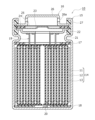
- 1 is a longitudinal sectional view of a cylindrical secondary battery according to an embodiment of the present invention
- 2 is a front view showing a positive electrode and a negative electrode constituting an electrode body provided in the cylindrical secondary battery of FIG. 1 in a developed state.
- the area of the positive electrode exposed portion for connecting the positive electrode tab is as small as possible. Therefore, it is possible to consider an embodiment in which the positive electrode exposed portion is not formed over the entire width direction of the positive electrode, but is formed only in the vicinity of the part where the positive electrode tab is connected. Furthermore, from the viewpoint of improving the reliability of the battery, the positive electrode exposed portion and its surroundings are covered with a protective material such as insulating tape. However, it has been found that when a positive electrode having such an embodiment is used, peeling of the positive electrode mixture layer is likely to occur starting from the side parallel to the width direction of the protective material due to the charge and discharge cycle.
- the inventors have conducted extensive research and found that peeling of the positive electrode mixture layer and a decrease in battery capacity can be suppressed by making the tacking strength T1 of the first positive electrode mixture layer aligned with the positive electrode exposed portion in the longitudinal direction of the positive electrode greater than the tacking strength T2 of the second positive electrode mixture layer adjacent to the positive electrode exposed portion and the first positive electrode mixture layer in the width direction of the positive electrode.
- FIG. 1 is a longitudinal cross-sectional view of a cylindrical secondary battery 10 (hereinafter, secondary battery 10) that is an example of an embodiment.
- secondary battery 10 an electrode body 14 and a non-aqueous electrolyte (not shown) are housed in an outer can 15.
- the sealing body 16 side will be referred to as the "top” and the bottom side of the outer can 15 as the "bottom”.
- the electrode body 14 has a wound structure in which the positive electrode 11 and the negative electrode 12 are wound with the separator 13 interposed therebetween.
- the positive electrode 11, the negative electrode 12, and the separator 13 are all long strip-shaped bodies, and are alternately stacked in the radial direction of the electrode body 14 by being wound in a spiral shape.
- the separator 13 is formed with dimensions slightly larger than the positive electrode 11 and the negative electrode 12, and two of them are arranged to sandwich the positive electrode 11.
- a porous sheet having ion permeability and insulating properties is used for the separator 13.
- porous sheets include a microporous thin film, a woven fabric, and a nonwoven fabric.
- Suitable materials for the separator include olefin resins such as polyethylene and polypropylene, and cellulose.
- the separator 13 may be a laminate having a cellulose fiber layer and a thermoplastic resin fiber layer such as an olefin resin.
- the separator 13 may be a multilayer separator including a polyethylene layer and a polypropylene layer, and a material such as an aramid resin or ceramic may be applied to the surface of the separator 13.
- the non-aqueous electrolyte has lithium ion conductivity.
- the non-aqueous electrolyte may be a liquid electrolyte (electrolytic solution) or a solid electrolyte.
- the liquid electrolyte contains a non-aqueous solvent and an electrolyte salt dissolved in the non-aqueous solvent.
- a non-aqueous solvent for example, esters, ethers, nitriles, amides, and mixed solvents of two or more of these are used as the non-aqueous solvent.
- the non-aqueous solvent include ethylene carbonate (EC), ethyl methyl carbonate (EMC), dimethyl carbonate (DMC), diethyl carbonate (DEC), and mixed solvents of these.
- the non-aqueous solvent may contain a halogen-substituted product (e.g., fluoroethylene carbonate, etc.) in which at least a part of the hydrogen of these solvents is replaced with a halogen atom such as fluorine.
- a halogen-substituted product e.g., fluoroethylene carbonate, etc.
- a lithium salt such as LiPF6 is used as the electrolyte salt.
- the solid electrolyte for example, a solid or gel-like polymer electrolyte, an inorganic solid electrolyte, etc. can be used.
- the inorganic solid electrolyte a material known in all-solid-state lithium ion secondary batteries, etc. (for example, an oxide-based solid electrolyte, a sulfide-based solid electrolyte, a halogen-based solid electrolyte, etc.) can be used.
- the polymer electrolyte includes, for example, a lithium salt and a matrix polymer, or a non-aqueous solvent, a lithium salt, and a matrix polymer.
- the matrix polymer for example, a polymer material that absorbs a non-aqueous solvent and gels is used.
- the polymer material for example, a fluororesin, an acrylic resin, a polyether resin, etc. can be used.
- the sealing body 16 seals the opening at the top of the outer can 15, sealing the inside of the secondary battery 10.
- Insulating plates 17 and 18 are provided above and below the electrode body 14.
- the positive electrode tab 19 extends vertically through the through hole of the insulating plate 17 and connects the filter 22, which is the bottom plate of the sealing body 16, to the positive electrode 11 included in the electrode body 14. This connects the positive electrode 11 to the sealing body 16, and in the secondary battery 10, the cap 26, which is the top plate of the sealing body 16 electrically connected to the filter 22, becomes the positive electrode terminal.
- the positive electrode tab 19 is, for example, an aluminum tab.
- the negative electrode tab 20 extends through the through hole of the insulating plate 18 to the bottom side of the outer can 15 and is welded to the inner surface of the bottom of the outer can 15. This connects the negative electrode 12 to the outer can 15, and in the secondary battery 10, the outer can 15 becomes the negative electrode terminal.
- the negative electrode tab 20 is, for example, a nickel tab.
- the number of positive electrode tabs 19 led out from the electrode body 14 is not particularly limited. By using multiple positive electrode tabs 19, the current collection of the positive electrode 11 is improved, and the output characteristics of the secondary battery 10 can be improved. The more the number of positive electrode tabs 19, the better the current collection of the positive electrode 11, but the cost of the secondary battery 10 increases. From the viewpoint of achieving both the above-mentioned effect and cost, the number of positive electrode tabs 19 is preferably 1 to 20, more preferably 1 to 10, and particularly preferably 3 to 8.
- the three or more positive electrode tabs 19 led out from the electrode body 14 may be directly connected to the sealing body 16, or may be connected to the sealing body 16 via a known current collecting member.
- the negative electrode tab 20 is extended from near the inner end of the negative electrode 12 and connected to the outer can 15, as shown in FIG. 1, for example.
- the position of the negative electrode tab 20 is not limited to the example shown in FIG. 1, and the negative electrode tab 20 may be provided only near the outer end of the negative electrode 12, or may be provided near both the inner end and the outer end of the negative electrode 12.
- a negative electrode exposed portion 44 may be formed at the outer end of the negative electrode 12, and the negative electrode exposed portion 44 may be brought into contact with the inner surface of the outer can 15, thereby electrically connecting the outer end of the negative electrode 12 to the outer can 15 without using a negative electrode tab 20.
- the outer can 15 is a cylindrical metal container with a bottom that is open on one axial side.
- a gasket 27 is provided between the outer can 15 and the sealing body 16 to ensure airtightness inside the secondary battery 10.
- the outer can 15 has a grooved portion 21 that supports the sealing body 16, formed, for example, by pressing the side portion from the outside.
- the grooved portion 21 is preferably formed in an annular shape along the circumferential direction of the outer can 15, and supports the sealing body 16 on its upper surface.
- the sealing body 16 has a filter 22, a lower valve body 23, an insulating member 24, an upper valve body 25, and a cap 26, which are stacked in this order from the electrode body 14 side.
- Each member constituting the sealing body 16 has, for example, a disk or ring shape, and each member except the insulating member 24 is electrically connected to each other.
- the lower valve body 23 and the upper valve body 25 are connected to each other at their respective centers, and the insulating member 24 is interposed between their respective peripheral edges. If the internal pressure of the battery increases due to abnormal heat generation, for example, the lower valve body 23 breaks, which causes the upper valve body 25 to swell toward the cap 26 and separate from the lower valve body 23, cutting off the electrical connection between them. If the internal pressure increases further, the upper valve body 25 breaks, and gas is discharged from the opening 26a of the cap 26.
- FIG. 2 is a front view showing the positive electrode 11 and the negative electrode 12 constituting the electrode body 14 of the secondary battery 10 of FIG. 1 in an expanded state.
- the negative electrode 12 is generally formed to have dimensions slightly larger than the positive electrode 11 in order to prevent lithium precipitation. In other words, the negative electrode 12 is formed to be longer in the longitudinal and transverse directions than the positive electrode 11.
- the positive electrode 11 has a positive electrode current collector 30 and a positive electrode mixture layer 32 disposed on the surface of the positive electrode current collector 30.
- a positive electrode exposed portion 34 where the positive electrode current collector 30 is exposed is disposed on the surface of the positive electrode 11, and the positive electrode exposed portion 34 contacts only one end 11a of both ends in the width direction of the positive electrode 11. In other words, the positive electrode exposed portion 34 does not extend to the other end 11b in the width direction of the positive electrode 11.
- the positive electrode mixture layer 32 exists between the positive electrode exposed portions 34, so the area of the positive electrode mixture layer 32 is increased, and the battery capacity of the secondary battery 10 is improved.
- the number of positive electrode exposed portions 34 is preferably 1 to 20, more preferably 1 to 10, and particularly preferably 3 to 8.
- the positive electrode exposed portion 34, the positive electrode tab 19, and the portion of the positive electrode mixture layer 32 adjacent to the positive electrode exposed portion 34 are covered with a protective member 36.
- the protective member 36 covers the positive electrode tab 19, the positive electrode exposed portion 34, and a portion of the positive electrode mixture layer 32.
- the protective member 36 is an insulating member that prevents the positive electrode tab 19 and the positive electrode exposed portion 34 from causing an internal short circuit with the opposing negative electrode mixture layer if the separator 13 is broken.
- the protective member 36 is, for example, an adhesive tape having a base portion and an adhesive portion formed on one surface of the base portion.
- a heat-resistant layer containing inorganic particles such as metal oxides can be provided between the base portion and the adhesive portion.
- the base portion can be made of any insulating resin, such as PPS (polyphenylene sulfide), PEEK (polyether ether ketone), PI (polyimide), PP (polypropylene), PET (polyethylene terephthalate), PBT (polybutylene terephthalate), etc.
- the thickness of the base portion is, for example, 5 ⁇ m or more and 50 ⁇ m or less.
- the adhesive portion is a portion for adhering the protective member 36 to the surface of the positive electrode 11.
- the thickness of the adhesive portion is, for example, 1 ⁇ m or more and 30 ⁇ m or less.
- the adhesive portion may contain at least one of a rubber-based polymer and an acrylic-based polymer.
- the rubber-based polymer and the acrylic-based polymer have adhesive properties, and therefore can adhere the protective member 36 to the surface of the positive electrode 11.
- the adhesive portion may further contain, for example, a silicone-based polymer.
- the positive electrode current collector 30 can be a foil of a metal such as aluminum that is stable in the potential range of the positive electrode, or a film with the metal disposed on the surface.
- the thickness of the positive electrode current collector 30 is, for example, 10 ⁇ m or more and 30 ⁇ m or less.
- the positive electrode mixture layer 32 is preferably formed on both sides of the positive electrode current collector 30.
- the thickness of the positive electrode mixture layer 32 is, for example, 10 ⁇ m or more and 150 ⁇ m or less on one side of the positive electrode current collector 30.
- the positive electrode mixture layer 32 contains, for example, a positive electrode active material, a conductive agent, and a binder.
- the positive electrode can be produced, for example, by applying a positive electrode mixture slurry containing a positive electrode active material, a conductive agent, a binder, etc. to both sides of the positive electrode current collector 30, drying the coating, and then rolling the coating using a roller or the like.
- the positive electrode active material contained in the positive electrode mixture layer 32 can be, for example, a lithium transition metal composite oxide containing a transition metal element such as Co, Mn, or Ni.
- lithium transition metal composite oxides include LixCoO2 , LixNiO2, LixMnO2 , LixCoyNi1 - yO2 , LixCoyM1-yOz , LixNi1 - yMyOz , LixMn2O4, LixMn2 - yMyO4 , LiMPO4, and Li2MPO4F
- M is at least one of Na, Mg , Sc , Y , Mn, Fe, Co, Ni , Cu, Zn, Al , Cr , Pb, Sb, and B ; 0 ⁇ x ⁇ 1.2, 0 ⁇ y ⁇ 0.9, and 2.0 ⁇ z ⁇ 2.3). These may be used alone or in combination of two or more kinds.
- the positive electrode active material preferably contains a lithium nickel composite oxide, in that it is possible to increase the capacity of the secondary battery 10.
- the lithium nickel composite oxide include Li x NiO 2 , Li x Co y Ni 1-y O 2 , and Li x Ni 1-y M y O z (M is at least one of Na, Mg, Sc, Y, Mn, Fe, Co, Ni, Cu, Zn, Al, Cr, Pb, Sb, and B; 0 ⁇ x ⁇ 1.2, 0 ⁇ y ⁇ 0.9, and 2.0 ⁇ z ⁇ 2.3).
- M is at least one of Na, Mg, Sc, Y, Mn, Fe, Co, Ni, Cu, Zn, Al, Cr, Pb, Sb, and B; 0 ⁇ x ⁇ 1.2, 0 ⁇ y ⁇ 0.9, and 2.0 ⁇ z ⁇ 2.3).
- the conductive agent contained in the positive electrode mixture layer 32 may be, for example, carbon-based particles such as carbon black (CB), acetylene black (AB), ketjen black, carbon nanotubes (CNT), graphene, and graphite. These may be used alone or in combination of two or more types.
- Binders contained in the positive electrode mixture layer 32 include, for example, fluorine-based resins such as polytetrafluoroethylene (PTFE) and polyvinylidene fluoride (PVDF), polyacrylonitrile (PAN), polyimide-based resins, acrylic-based resins, and polyolefin-based resins. These may be used alone or in combination of two or more types.
- fluorine-based resins such as polytetrafluoroethylene (PTFE) and polyvinylidene fluoride (PVDF), polyacrylonitrile (PAN), polyimide-based resins, acrylic-based resins, and polyolefin-based resins. These may be used alone or in combination of two or more types.
- the positive electrode mixture layer 32 can be divided into a first positive electrode mixture layer 38 aligned with the positive electrode exposed portion 34 in the longitudinal direction of the positive electrode 11, and a second positive electrode mixture layer 39 adjacent to the positive electrode exposed portion 34 and the first positive electrode mixture layer 38 in the width direction of the positive electrode 11.
- the width direction length t1 of the first positive electrode mixture layer 38 and the width direction length t2 of the second positive electrode mixture layer 39 preferably satisfy the relationship 1/10 ⁇ t1/t2 ⁇ 1, and more preferably satisfy the relationship 1/8 ⁇ t1/t2 ⁇ 1/2.
- the tacking strength T1 of the first positive electrode mixture layer 38 and the tacking strength T2 of the second positive electrode mixture layer 39 satisfy the relationship T1>T2. This makes it possible to suppress peeling of the positive electrode mixture layer 32 and a decrease in battery capacity. Because peeling is likely to occur in the first positive electrode mixture layer 38 starting from the side 36a parallel to the width direction of the protective member 36 due to charge/discharge cycles, it is preferable that the first positive electrode mixture layer 38 has a relatively high tack strength. On the other hand, peeling is less likely to occur in the second positive electrode mixture layer 39 than in the first positive electrode mixture layer 38, so from the viewpoint of improving battery capacity, it is preferable that the tack strength is smaller than that of the first positive electrode mixture layer 38.
- T1 and T2 preferably satisfy the relationship 1.03 ⁇ T1/T2 ⁇ 1.68, and more preferably satisfy the relationship 1.10 ⁇ T1/T2 ⁇ 1.42.
- T1 is preferably 320N or more and 520N or less, and more preferably 340N or more and 440N or less.
- T2 is, for example, 250N or more and 400N or less.
- the tack strength of the first positive electrode mixture layer 38 and the second positive electrode mixture layer 39 can be measured using a commercially available tack tester (for example, TAC-II manufactured by Rhesca Corporation). Specific measurement conditions etc. are as follows. [Test sample] The first positive electrode mixture layer 38 and the second positive electrode mixture layer 39 are each cut to a predetermined size from the positive electrode 11 to prepare a test sample. When the positive electrode 11 is incorporated in a battery, the battery is disassembled to remove the positive electrode 11, and the positive electrode 11 is vacuum-dried for one hour, after which it can be cut to prepare a test sample.
- TAC-II manufactured by Rhesca Corporation
- a double-sided tape #515 manufactured by Nitto Denko is attached to the tip of a metal rod with an adhesive area of 2 mm ⁇ , and the test sample is pressed with a preload of 400 gf for 10 seconds, and then peeled off at a speed of 600 mm/min. The stress required for peeling is measured. Five samples each of the first positive electrode mixture layer 38 and the second positive electrode mixture layer 39 are measured, and the average of the measured values is taken as the tacking strength (N).
- the tacking strength of the positive electrode mixture layer 32 can be adjusted, for example, by subjecting the positive electrode mixture layer 32 to a heat treatment. More specifically, T1, T2, and T1/T2 can be adjusted to the above ranges by subjecting only the first positive electrode mixture layer 38 to a heat treatment and not subjecting the second positive electrode mixture layer 39 to a heat treatment.
- the tacking strength can be increased by increasing the heat treatment temperature.
- the tacking strength can also be increased by increasing the heat treatment time.
- the heat treatment temperature can be, for example, 100°C or higher and 250°C or lower.
- the heat treatment time can be, for example, 3 seconds or higher and 60 seconds or lower.
- the heat treatment of the positive electrode mixture layer 32 can be performed, for example, by contacting only the first positive electrode mixture layer 38 with a high-temperature roller.
- the heat treatment temperature and heat treatment time can be adjusted by adjusting the temperature and rotation speed of the roller.
- the tacking strength increases as described above, but the battery capacity may decrease. This is thought to be because the binder, in particular, among the components contained in the positive electrode mixture layer 32, forms a film on the surface of the active material.
- the peel strength P1 of the first positive electrode mixture layer and the peel strength P2 of the second positive electrode mixture layer preferably satisfy the relationship P1>P2. It is more preferable that P1 and P2 satisfy the relationship 1.13 ⁇ P1/P2 ⁇ 1.63, and it is particularly preferable that they satisfy the relationship 1.19 ⁇ P1/P2 ⁇ 1.38.
- P1 is preferably 9 N/m or more and 13 N/m or less, and more preferably 9.5 N/m or more and 11 N/m or less.
- P2 is, for example, 6 N/m or more and 10 N/m or less.
- the peel strength of the first positive electrode mixture layer 38 and the second positive electrode mixture layer 39 can be measured, for example, as follows.
- Test sample The first positive electrode mixture layer 38 and the second positive electrode mixture layer 39 are each cut to a predetermined size from the positive electrode 11 to prepare a test sample.
- the battery is disassembled to remove the positive electrode 11, and the positive electrode 11 is vacuum-dried for one hour, after which it can be cut to prepare a test sample.
- Measurement conditions A double-sided tape #515 manufactured by Nitto Denko is attached to the positive electrode mixture layer 32 on one side of the test piece, and the test piece is fixed to a stainless steel substrate having a smooth surface.
- the stainless steel substrate to which the test sample is fixed is placed so as to be horizontal.
- One end of the positive electrode current collector 30 in the longitudinal direction of the test sample is fixed to a movable jig of a tensile tester (for example, Tensilon universal tester RTC1210 manufactured by A&D Co., Ltd.), and the positive electrode current collector 30 is set to be peeled in a direction of 90° with respect to the substrate surface of the stainless steel substrate.
- the movable jig is moved to peel the positive electrode mixture layer 32 of the test piece from the positive electrode current collector 30 at a speed of 20 mm/min.
- the tensile direction is always maintained at 90° with respect to the substrate surface of the stainless steel substrate to which the test piece is fixed.
- a stable tensile strength value is read when the test sample is peeled off by 30 mm or more. Measurements are performed on five samples each of the first positive electrode mixture layer 38 and the second positive electrode mixture layer 39, and the average of the measured values is taken as the peel strength (N/m).
- the negative electrode 12 has a negative electrode current collector 40 and a negative electrode mixture layer 42 disposed on the surface of the negative electrode current collector 40.
- the negative electrode 12 has a negative electrode exposed portion 44 where the negative electrode current collector 40 is exposed, for example, at the end of the inner winding in the longitudinal direction, and the negative electrode tab 20 is connected to the negative electrode exposed portion 44.
- the negative electrode current collector can be a foil of a metal such as copper that is stable in the potential range of the negative electrode, or a film with the metal disposed on the surface.
- the thickness of the negative electrode current collector is, for example, 5 ⁇ m or more and 30 ⁇ m or less.
- the negative electrode mixture layer is preferably formed on both sides of the negative electrode current collector.
- the thickness of the negative electrode mixture layer is, for example, 10 ⁇ m or more and 150 ⁇ m or less on one side of the negative electrode current collector.
- the negative electrode mixture layer contains, for example, a negative electrode active material and a binder.
- the negative electrode can be produced, for example, by applying a negative electrode mixture slurry containing a negative electrode active material, a binder, etc. to both sides of the negative electrode current collector, drying the coating, and then rolling the coating using a roller or the like.
- the negative electrode active material contained in the negative electrode mixture layer is not particularly limited as long as it can reversibly absorb and release lithium ions, and generally carbon materials such as graphite are used.
- the graphite may be any of natural graphite such as flake graphite, lump graphite, and earthy graphite, lump artificial graphite, and artificial graphite such as graphitized mesophase carbon microbeads.
- the negative electrode active material may be a metal that alloys with Li, such as Si or Sn, a metal compound containing Si or Sn, or a lithium titanium composite oxide.
- a Si-containing compound in which Si is dispersed in a carbon material may be used in combination with graphite.
- Binders contained in the negative electrode mixture layer include, for example, styrene butadiene rubber (SBR), nitrile butadiene rubber (NBR), carboxymethyl cellulose (CMC) or its salts, polyacrylic acid (PAA) or its salts (PAA-Na, PAA-K, etc., or it may be a partially neutralized salt), polyvinyl alcohol (PVA), etc. These may be used alone or in combination of two or more types.
- SBR styrene butadiene rubber
- NBR nitrile butadiene rubber
- CMC carboxymethyl cellulose
- PAA polyacrylic acid
- PAA-Na polyacrylic acid
- PAA-K polyvinyl alcohol
- PVA polyvinyl alcohol
- Example 1-1 [Preparation of positive electrode]
- the positive electrode active material aluminum-containing lithium nickel cobalt oxide represented by LiNi 0.88 Co 0.09 Al 0.03 O 2 was used. 100 parts by mass of the positive electrode active material, 1 part by mass of acetylene black (AB), and 1 part by mass of polyvinylidene fluoride (PVDF) were mixed, and an appropriate amount of N-methyl-2-pyrrolidone (NMP) was added to prepare a positive electrode mixture slurry. Next, the positive electrode mixture slurry was applied to both sides of a belt-shaped positive electrode current collector made of aluminum foil with a thickness of 15 ⁇ m so that eight positive electrode exposed parts were formed. As shown in the example in FIG. 2, the positive electrode exposed parts were made to contact only one end in the width direction of the positive electrode. t1/t2 calculated from the width direction length t1 of the first positive electrode mixture layer and the width direction length t2 of the second positive electrode mixture layer was 1/5.
- the area corresponding to the first positive electrode mixture layer was heat-treated by contacting it with a roller at 180°C for 10 seconds.
- the electrode was cut to a predetermined plate size to produce a positive electrode in which a positive electrode mixture layer was formed on both sides of the positive electrode current collector.
- an aluminum positive electrode tab was welded to each of the eight positive electrode exposed parts, and insulating tape was applied so as to cover the positive electrode exposed parts, the positive electrode tab, and a part of the positive electrode mixture layer adjacent to the positive electrode mixture layer.
- the tacking strength T1 was 370 N and the peel strength P1 was 10 N/m.
- the tacking strength T1 was 310 N and the peel strength P1 was 8 N/m.
- a negative electrode mixture slurry 95 parts by mass of graphite, 5 parts by mass of Si oxide (SiO), 1 part by mass of sodium carboxymethylcellulose (CMC-Na), and 1 part by mass of styrene butadiene rubber (SBR) were mixed, and an appropriate amount of water was added to prepare a negative electrode mixture slurry.
- the negative electrode mixture slurry was applied to both sides of a strip-shaped negative electrode current collector made of copper foil with a thickness of 8 ⁇ m, dried, rolled, and cut to a predetermined electrode plate size to prepare a negative electrode in which a negative electrode mixture layer was formed on both sides of the negative electrode current collector.
- a negative electrode exposed portion in which no mixture layer was present and the current collector surface was exposed was provided at the inner end of the negative electrode, and a nickel negative electrode tab was welded to the negative electrode exposed portion.
- a non-aqueous electrolyte was prepared by adding 5 parts by mass of vinylene carbonate (VC) to 100 parts by mass of a mixed solvent prepared by mixing ethylene carbonate (EC) and dimethyl carbonate (DMC) in a volume ratio of 3:7, and dissolving lithium hexafluorophosphate (LiPF 6 ) at a concentration of 1.5 mol/L.
- VC vinylene carbonate
- DMC dimethyl carbonate
- a wound electrode assembly was prepared by spirally winding a positive electrode and a negative electrode with a polyethylene microporous membrane separator interposed therebetween.
- the electrode assembly was housed in a bottomed cylindrical exterior can, the negative electrode tab was welded to the bottom of the bottomed cylindrical exterior can, and the positive electrode tab was welded to a sealing member. After injecting a nonaqueous electrolyte into the exterior can, the opening of the exterior can was sealed with a sealing member via a gasket to prepare a cylindrical test cell.
- Capacity retention rate (discharge capacity at 500th cycle/discharge capacity at 1st cycle) ⁇ 100 [Charge/discharge cycle]
- the test cell was charged at a constant current of 0.3 C until the battery voltage reached 4.2 V, and then charged at a constant voltage of 4.2 V until the current value reached 0.01 C. Thereafter, the test cell was discharged at a constant current of 0.5 C until the battery voltage reached 2.5 V, and this charge/discharge cycle was counted as one cycle.
- Example 1-2 A test cell was prepared and evaluated in the same manner as in Example 1-1, except that the roller temperature was changed to 130° C. in the preparation of the positive electrode.
- Example 1-3 A test cell was prepared and evaluated in the same manner as in Example 1-1, except that the roller temperature was changed to 140° C. in the preparation of the positive electrode.
- Example 1-4 A test cell was prepared and evaluated in the same manner as in Example 1-1, except that in the preparation of the positive electrode, the roller contact time was changed to 20 seconds.
- Example 1-5 A test cell was prepared and evaluated in the same manner as in Example 1-1, except that in the preparation of the positive electrode, the roller contact time was changed to 30 seconds.
- Example 1-1 A test cell was prepared and evaluated in the same manner as in Example 1-1, except that no heat treatment was performed in the preparation of the positive electrode.
- Example 1-2 In the preparation of the positive electrode, a test cell was prepared and evaluated in the same manner as in Example 1-1, except that the portion corresponding to the second positive electrode mixture layer was also subjected to heat treatment in the same manner as in the first positive electrode mixture layer.
- Example 2 In the preparation of the positive electrode, the number of positive electrode exposed portions was changed to three, and an aluminum positive electrode tab was welded to each of the three positive electrode exposed portions. A test cell was prepared and evaluated in the same manner as in Example 1-1.
- Example 2 A test cell was prepared and evaluated in the same manner as in Example 2, except that no heat treatment was performed in the preparation of the positive electrode.
- Example 3 A test cell was produced and evaluated in the same manner as in Example 1-1, except that in the preparation of the positive electrode, the number of positive electrode exposed portions was changed to one, and an aluminum positive electrode tab was welded to this positive electrode exposed portion.
- Example 3 A test cell was prepared and evaluated in the same manner as in Example 3, except that no heat treatment was performed in the preparation of the positive electrode.
- Tables 1 and 2 The evaluation results of the test cells according to the examples and comparative examples are shown in Tables 1 and 2.
- Table 2 the results of Example 1-1 and Comparative Example 1-1 shown in Table 1 are listed again to show the relationship between the effect of suppressing peeling of the positive electrode mixture layer and the number of exposed positive electrode portions.
- the column of the number of peeled positive electrode mixture layers for the test cells of Examples 1-1, 2, and 3 the difference in the number of peeled layers from the corresponding test cells of Comparative Examples 1-1, 2, and 3 is shown in parentheses.
- test cells of Examples 1-1 to 1-5 were able to obtain a high capacity retention rate while suppressing peeling of the positive electrode mixture layer.
- test cells of Comparative Examples 1-1 to 1-2 were unable to simultaneously suppress peeling of the positive electrode mixture layer after charge/discharge cycles and suppress the decrease in battery capacity.
- results shown in Table 2 show that the greater the number of exposed positive electrode portions in a test cell, the greater the effect of suppressing peeling of the positive electrode mixture layer.
- a cylindrical secondary battery comprising an electrode assembly in which a positive electrode and a negative electrode are wound with a separator interposed therebetween, a non-aqueous electrolyte, and a cylindrical outer can for accommodating the electrode assembly and the non-aqueous electrolyte, the positive electrode has a positive electrode current collector and a positive electrode mixture layer disposed on a surface of the positive electrode current collector, a positive electrode exposed portion in which the positive electrode current collector is exposed is disposed on a surface of the positive electrode, the positive electrode exposed portion is in contact with only one of both widthwise ends of the positive electrode, a positive electrode tab is connected to the positive electrode exposed portion and led out from the one end portion; a protective member covers the positive electrode exposed portion, the positive electrode tab, and a portion of the positive electrode mixture layer adjacent to the positive electrode exposed portion, When the positive electrode mixture layer is divided into a first positive electrode mixture layer aligned with the positive electrode exposed portion in the longitudinal direction of the positive electrode, and a second
- Configuration 2 2. The cylindrical secondary battery according to claim 1, wherein T1 and T2 satisfy the relationship: 1.03 ⁇ T1/T2 ⁇ 1.68.
- Configuration 3 2. The cylindrical secondary battery according to claim 1, wherein T1 and T2 satisfy the relationship of 1.10 ⁇ T1/T2 ⁇ 1.42.
- Configuration 4 The cylindrical secondary battery according to any one of configurations 1 to 3, wherein T1 is 320N or more and 520N or less.
- Configuration 5 The cylindrical secondary battery according to any one of configurations 1 to 4, wherein a plurality of the positive electrode exposed portions are arranged on the surface of the positive electrode.
- Configuration 6 The cylindrical secondary battery according to any one of configurations 1 to 5, wherein a peel strength P1 of the first positive electrode mixture layer and a peel strength P2 of the second positive electrode mixture layer satisfy a relationship of P1>P2.
- Configuration 7 7. The cylindrical secondary battery according to claim 6, wherein P1 and P2 satisfy the relationship: 1.13 ⁇ P1/P2 ⁇ 1.63.
- Configuration 8 7. The cylindrical secondary battery according to claim 6, wherein P1 and P2 satisfy the relationship: 1.19 ⁇ P1/P2 ⁇ 1.38.
- Configuration 9 The cylindrical secondary battery according to any one of configurations 6 to 8, wherein P1 is 9 N/m or more and 13 N/m or less.
Landscapes
- Battery Electrode And Active Subsutance (AREA)
- Secondary Cells (AREA)
Priority Applications (1)
| Application Number | Priority Date | Filing Date | Title |
|---|---|---|---|
| JP2025516691A JPWO2024225021A1 (https=) | 2023-04-28 | 2024-04-09 |
Applications Claiming Priority (2)
| Application Number | Priority Date | Filing Date | Title |
|---|---|---|---|
| JP2023074088 | 2023-04-28 | ||
| JP2023-074088 | 2023-04-28 |
Publications (1)
| Publication Number | Publication Date |
|---|---|
| WO2024225021A1 true WO2024225021A1 (ja) | 2024-10-31 |
Family
ID=93256265
Family Applications (1)
| Application Number | Title | Priority Date | Filing Date |
|---|---|---|---|
| PCT/JP2024/014368 Ceased WO2024225021A1 (ja) | 2023-04-28 | 2024-04-09 | 円筒形二次電池 |
Country Status (2)
| Country | Link |
|---|---|
| JP (1) | JPWO2024225021A1 (https=) |
| WO (1) | WO2024225021A1 (https=) |
Citations (5)
| Publication number | Priority date | Publication date | Assignee | Title |
|---|---|---|---|---|
| JP2011134564A (ja) * | 2009-12-24 | 2011-07-07 | Toyota Motor Corp | リチウムイオン二次電池、車両及び電池搭載機器 |
| JP2016115568A (ja) * | 2014-12-16 | 2016-06-23 | 日本ゼオン株式会社 | リチウムイオン電池用電極の製造方法 |
| JP2016115603A (ja) * | 2014-12-17 | 2016-06-23 | 日本ゼオン株式会社 | リチウムイオン電池用電極の製造方法 |
| EP3961750A1 (en) * | 2020-08-31 | 2022-03-02 | Ningde Amperex Technology Limited | Electrode plate, electrochemical apparatus, and electronic apparatus |
| WO2022209112A1 (ja) * | 2021-03-31 | 2022-10-06 | パナソニックIpマネジメント株式会社 | 二次電池用電極、二次電池、及び二次電池用電極の製造方法 |
-
2024
- 2024-04-09 WO PCT/JP2024/014368 patent/WO2024225021A1/ja not_active Ceased
- 2024-04-09 JP JP2025516691A patent/JPWO2024225021A1/ja active Pending
Patent Citations (5)
| Publication number | Priority date | Publication date | Assignee | Title |
|---|---|---|---|---|
| JP2011134564A (ja) * | 2009-12-24 | 2011-07-07 | Toyota Motor Corp | リチウムイオン二次電池、車両及び電池搭載機器 |
| JP2016115568A (ja) * | 2014-12-16 | 2016-06-23 | 日本ゼオン株式会社 | リチウムイオン電池用電極の製造方法 |
| JP2016115603A (ja) * | 2014-12-17 | 2016-06-23 | 日本ゼオン株式会社 | リチウムイオン電池用電極の製造方法 |
| EP3961750A1 (en) * | 2020-08-31 | 2022-03-02 | Ningde Amperex Technology Limited | Electrode plate, electrochemical apparatus, and electronic apparatus |
| WO2022209112A1 (ja) * | 2021-03-31 | 2022-10-06 | パナソニックIpマネジメント株式会社 | 二次電池用電極、二次電池、及び二次電池用電極の製造方法 |
Also Published As
| Publication number | Publication date |
|---|---|
| JPWO2024225021A1 (https=) | 2024-10-31 |
Similar Documents
| Publication | Publication Date | Title |
|---|---|---|
| JP5444781B2 (ja) | リチウムイオン二次電池用電極及びリチウムイオン二次電池 | |
| CN106654164B (zh) | 非水电解质二次电池用正极和非水电解质二次电池 | |
| WO2010134258A1 (ja) | 非水電解質二次電池用電極板及び非水電解質二次電池 | |
| WO2009144919A1 (ja) | 円筒形非水電解液二次電池 | |
| JP7763174B2 (ja) | 非水電解質二次電池 | |
| JP2010225539A (ja) | リチウムイオン二次電池用電極及びリチウムイオン二次電池 | |
| WO2023283835A1 (zh) | 电化学装置及电子装置 | |
| JP7372981B2 (ja) | 電気化学装置及びその電気化学装置を含む電子装置 | |
| JP7738017B2 (ja) | 非水電解質二次電池 | |
| JP6656370B2 (ja) | リチウムイオン二次電池および組電池 | |
| EP4350798A1 (en) | Non-aqueous electrolyte secondary battery | |
| JP2000090979A (ja) | 密閉型電池 | |
| WO2022190895A1 (ja) | 非水電解質二次電池 | |
| WO2024225021A1 (ja) | 円筒形二次電池 | |
| WO2019065871A1 (ja) | 円筒形二次電池 | |
| CN114024103A (zh) | 电化学装置和电子装置 | |
| WO2025047844A1 (ja) | 円筒形二次電池 | |
| JP4228665B2 (ja) | 非水電解液二次電池 | |
| WO2020059873A1 (ja) | 二次電池 | |
| US20260074204A1 (en) | Electrode active material and battery | |
| WO2024224996A1 (ja) | 二次電池 | |
| WO2026048578A1 (ja) | 二次電池用電極及び二次電池 | |
| WO2025225437A1 (ja) | 非水電解質二次電池 | |
| WO2025197719A1 (ja) | 非水電解質二次電池 | |
| WO2025192508A1 (ja) | 非水電解質二次電池 |
Legal Events
| Date | Code | Title | Description |
|---|---|---|---|
| 121 | Ep: the epo has been informed by wipo that ep was designated in this application |
Ref document number: 24796777 Country of ref document: EP Kind code of ref document: A1 |
|
| ENP | Entry into the national phase |
Ref document number: 2025516691 Country of ref document: JP Kind code of ref document: A |
|
| WWE | Wipo information: entry into national phase |
Ref document number: 2025516691 Country of ref document: JP |
|
| NENP | Non-entry into the national phase |
Ref country code: DE |