WO2024224816A1 - 切削インサート、切削工具及び切削加工物の製造方法 - Google Patents
切削インサート、切削工具及び切削加工物の製造方法 Download PDFInfo
- Publication number
- WO2024224816A1 WO2024224816A1 PCT/JP2024/008675 JP2024008675W WO2024224816A1 WO 2024224816 A1 WO2024224816 A1 WO 2024224816A1 JP 2024008675 W JP2024008675 W JP 2024008675W WO 2024224816 A1 WO2024224816 A1 WO 2024224816A1
- Authority
- WO
- WIPO (PCT)
- Prior art keywords
- openings
- insert
- cutting
- fixing hole
- holder
- Prior art date
- Legal status (The legal status is an assumption and is not a legal conclusion. Google has not performed a legal analysis and makes no representation as to the accuracy of the status listed.)
- Ceased
Links
Images





Classifications
-
- B—PERFORMING OPERATIONS; TRANSPORTING
- B23—MACHINE TOOLS; METAL-WORKING NOT OTHERWISE PROVIDED FOR
- B23B—TURNING; BORING
- B23B27/00—Tools for turning or boring machines; Tools of a similar kind in general; Accessories therefor
- B23B27/14—Cutting tools of which the bits or tips or cutting inserts are of special material
-
- B—PERFORMING OPERATIONS; TRANSPORTING
- B23—MACHINE TOOLS; METAL-WORKING NOT OTHERWISE PROVIDED FOR
- B23B—TURNING; BORING
- B23B27/00—Tools for turning or boring machines; Tools of a similar kind in general; Accessories therefor
- B23B27/14—Cutting tools of which the bits or tips or cutting inserts are of special material
- B23B27/16—Cutting tools of which the bits or tips or cutting inserts are of special material with exchangeable cutting bits or cutting inserts, e.g. able to be clamped
-
- B—PERFORMING OPERATIONS; TRANSPORTING
- B23—MACHINE TOOLS; METAL-WORKING NOT OTHERWISE PROVIDED FOR
- B23C—MILLING
- B23C5/00—Milling-cutters
- B23C5/16—Milling-cutters characterised by physical features other than shape
- B23C5/20—Milling-cutters characterised by physical features other than shape with removable cutter bits or teeth or cutting inserts
- B23C5/22—Securing arrangements for bits or teeth or cutting inserts
-
- B—PERFORMING OPERATIONS; TRANSPORTING
- B23—MACHINE TOOLS; METAL-WORKING NOT OTHERWISE PROVIDED FOR
- B23Q—DETAILS, COMPONENTS, OR ACCESSORIES FOR MACHINE TOOLS, e.g. ARRANGEMENTS FOR COPYING OR CONTROLLING; MACHINE TOOLS IN GENERAL CHARACTERISED BY THE CONSTRUCTION OF PARTICULAR DETAILS OR COMPONENTS; COMBINATIONS OR ASSOCIATIONS OF METAL-WORKING MACHINES, NOT DIRECTED TO A PARTICULAR RESULT
- B23Q3/00—Devices holding, supporting, or positioning work or tools, of a kind normally removable from the machine
- B23Q3/155—Arrangements for automatic insertion or removal of tools, e.g. combined with manual handling
Definitions
- the present disclosure relates to a cutting insert, a cutting tool, and a method for manufacturing a machined product.
- cutting tools include rotary tools and turning tools.
- rotary tools include milling tools.
- the turning tools can be used for milling processes such as face milling and end milling.
- turning tools include external diameter machining tools, internal diameter machining tools, grooving tools, and cut-off tools.
- Patent Documents 1 and 2 propose a configuration in which a recess is provided on the top surface of the insert in order to improve the positioning accuracy when attaching the insert to the holder.
- a cutting insert has a body that is detachably attached to a holder.
- the body has an upper surface, a lower surface opposite the upper surface, a side surface connected to the upper surface and the lower surface, a cutting edge located at the intersection of the upper surface and the side surface, fixing holes that open on the upper surface and the lower surface and into which a fixing member for fixing the body to the holder can be inserted, and a plurality of through openings that open on the upper surface and the lower surface and are located away from the fixing holes.
- FIG. 1 is a perspective view of a cutting tool according to an embodiment of the present disclosure.
- FIG. 2 is an enlarged view of region II shown in FIG. 2 is a plan view of the cutting tool shown in FIG. 1 as viewed from a first end side.
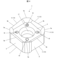
- FIG. FIG. 2 is a perspective view of an insert in the cutting tool shown in FIG. 1 .
- FIG. 5 is a top view of the insert shown in FIG. 4 .
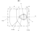
- FIG. 6 is an enlarged view of region VI shown in FIG. 5 .
- FIG. 5 is a top view of the insert shown in FIG. 4 .
- FIG. 6 is an enlarged view of region VI shown in FIG. 5 .
- FIG. 2 is a schematic diagram showing a step of a manufacturing method of a machined product according to an embodiment of the present disclosure.
- FIG. 2 is a schematic diagram showing a step of a manufacturing method of a machined product according to an embodiment of the present disclosure.
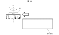
- FIG. 2 is a schematic diagram showing a step of a manufacturing method of a machined product according to an embodiment of the present disclosure.
- the cutting insert 1 (insert 1), cutting tool 101, and method for manufacturing a machined product according to the embodiments of the present disclosure will be described in detail below with reference to the drawings.
- each of the drawings referred to below shows a simplified version of only the components necessary for explaining the embodiments. Therefore, the insert 1, cutting tool 101, and method for manufacturing a machined product according to the embodiments of the present disclosure may include any components not shown in each of the drawings referred to.
- the dimensions of the components in each drawing do not faithfully represent the actual dimensions of the components and the dimensional ratios of each member, etc.
- a cutting tool 101 is a rotary tool used for turning.
- the cutting tool 101 may be a turning tool used for turning such as external diameter machining, internal diameter machining, and grooving.
- the cutting tool 101 may have a holder 103 and an insert 1.
- the insert 1 in the cutting tool 101 is a member that comes into contact with a workpiece and cuts the workpiece.
- the holder 103 is a member that holds the insert 1 and is attached to a machine tool.
- the holder 103 has a cylindrical shape extending from a first end 103a to a second end 103b along the rotation axis O1.
- the direction of rotation about the rotation axis O1 is indicated by Y1. If the cutting tool 101 is a tool used for turning as described above, the rotation axis O1 may be replaced with the central axis.
- the holder 103 may have a pocket 105 located on the side of the first end 103a. There may be only one pocket 105, or there may be multiple pockets 105 as in the example shown in FIG. 1. As in the example shown in FIG. 1, the multiple pockets 105 may each open to the outer circumferential surface of the holder 103 and the end face on the side of the first end 103a. As in the example shown in FIG. 3, when the cutting tool 101 is viewed from the front from the side of the second end 103b, the multiple pockets 105 may be arranged at equal or unequal intervals.
- the holder 103 has multiple pockets 105, so the holder 103 does not have to be cylindrical in the strict sense.
- the pockets 105 are spaces in which the insert 1 is positioned.
- the pockets 105 may also be used as spaces through which chips generated during cutting to manufacture machined products can flow.
- the holder 103 may be made of steel, cast iron, or the like.
- steel may be used among these materials.
- the insert 1 is located in the pocket 105 and is removably attached to the holder 103 using a fixing member 107.
- the fixing member 107 include a clamp member and a screw.
- a screw is used as the fixing member 107, and the insert 1 is fixed to the holder 103 by the screw.
- the insert 1 has a main body 3 that is detachably attached to a holder 103.
- the main body 3 has a polygonal plate shape and has an upper surface 5, a lower surface 7, a side surface 9, and a cutting edge 11, as in the example shown in FIG.
- the upper surface 5 may be polygonal and have multiple corners 5a and multiple sides 5b.
- the upper surface 5 may be located relatively forward in the rotational direction Y1 of the insert 1 when the insert 1 is attached to the holder 103.
- the upper surface 5 may be shaped with 180° rotational symmetry with respect to the center of the upper surface 5, as in the example shown in FIG. 5.
- the center of the upper surface 5 can be identified, for example, by the intersection of the diagonals of the upper surface 5.
- the lower surface 7 may be located on the opposite side of the upper surface 5, and may be located relatively backward in the rotational direction Y1 of the insert 1 when the insert 1 is attached to the holder 103.
- the side surface 9 of the insert 1 may be located between the upper surface 5 and the lower surface 7.
- the side surface 9 may be connected to each of the upper surface 5 and the lower surface 7.
- the side surface 9 since the upper surface 5 is polygonal, the side surface 9 has a flat surface area located along the edge 5b of the upper surface 5 and a convex surface area located along the corner 5a of the upper surface 5.
- the example insert 1 shown in FIG. 4 has a generally rectangular plate shape, with the upper surface 5 and the lower surface 7 each being generally rectangular.
- the side surface 9 has four flat surface areas and four convex surface areas.
- the shape of the insert 1 is not limited to the above configuration.
- the upper surface 5 may not be rectangular, but may be, for example, generally triangular, generally pentagonal, or generally hexagonal.
- the insert 1 has an upper cutting edge 13 as a cutting edge 11 located at the intersection of the top surface 5 and the side surface 9.
- the upper cutting edge 13 may be located over the entire intersection of the top surface 5 and the side surface 9, or may be located over only a portion of this intersection.
- the top surface 5 can function as a scooping surface.
- the side surface 9 can function as a clearance surface.
- the insert 1 may have a lower cutting edge 15 as a cutting edge 11 located at the intersection of the lower surface 7 and the side surface 9.
- the lower cutting edge 15 may be located over the entire intersection of the lower surface 7 and the side surface 9, or may be located over only a portion of this intersection.
- the lower surface 7 can function as a scooping surface.
- the side surface 9 can function as a clearance surface.
- either the upper cutting edge 13 or the lower cutting edge 15 is used.
- the upper cutting edge 13 is used for cutting. If the upper cutting edge 13 wears down to a predetermined amount or more, the insert 1 may be removed from the pocket 105, turned upside down (front and back), and then reattached to the pocket 105. In this case, the upper surface 5 of the insert 1 abuts against the pocket 105, and the lower cutting edge 15 can be used for cutting.
- the main body 3 may also have a fixing hole 17 and a plurality of through openings 19. These fixing holes 17 and the plurality of through openings 19 are through holes that open on the upper surface 5 and the lower surface 7, respectively.
- the fixing hole 17 in the insert 1 is a portion into which a fixing member 107 can be inserted to fix the insert 1 (main body 3) when attaching or detaching the insert 1 to the holder 103 (see FIG. 2).
- the fixing holes 17 open at the center of the upper surface 5 and at the center of the lower surface 7.
- a screw which is the fixing member 107, is inserted into the fixing hole 17 and fixed to the pocket 105, thereby fixing the insert 1 to the holder 103.
- the end of the fixing hole 17 on the side of the upper surface 5 may be tapered so that the inner diameter increases as it approaches the upper surface 5.
- the end of the fixing hole 17 on the side of the lower surface 7 may be tapered so that the inner diameter increases as it approaches the lower surface 7.
- the fixing member 107 can easily come into contact with the tapered portion, and the insert 1 can be stably fixed to the holder 103.
- the pocket 105 in the holder 103 has a restraining seat 109 against which the lower surface 7 of the insert 1 abuts, and a restraining side surface 111 against which the side surface 9 of the insert 1 abuts.
- the restraining seat 109 may be a square shape corresponding to the lower surface 7, and the restraining side surface 111 may be composed of two flat surface areas corresponding to the two flat surface areas on the side surface 9.
- the restraining seat 109 may also be provided with a screw hole into which a fixing member 107 (screw) is screwed.
- the screw hole includes the central axis of the fixing hole 17 in the insert 1 and extends in a direction along the central axis.
- the multiple through openings 19 in the insert 1 are portions that can be used to grip the insert 1 when attaching or detaching the insert 1 to or from the holder 103.
- the main body 3 can be gripped when attaching or detaching the main body 3 to or from the holder 103.
- a gripping member such as a pin can be inserted into at least two of the multiple through openings 19 to pinch the main body 3.
- each of the multiple through openings 19 is located away from the fixing hole 17. Therefore, a distance can be secured between the gripping member that grips the main body 3 and the robot hand that attaches and removes the fixing member. This allows the fixing member 107 to be removed while gripping the main body 3, allowing for stable automation of the replacement of the insert 1.
- each of the multiple through openings 19 will also be simply referred to as multiple through openings 19.
- the main body 3 can be gripped when attaching or detaching the main body 3 to the holder 103 regardless of whether the upper cutting edge 13 or the lower cutting edge 15 is being used. Also, the portion for gripping the main body 3 is not formed by the side surface 9 but by the multiple through openings 19 described above. Therefore, the cutting tool 101 is highly versatile for the following reasons.
- the side surface 9 of the insert 1 abuts against the pocket 105 (restraining side surface 111). If a portion for gripping the main body 3 is formed on the side surface 9, the area of the side surface 9 of the insert 1 that abuts against the pocket 105 is restricted in order to secure this portion. Also, in order to secure an area of the side surface 9 of the insert 1 that abuts against the pocket 105, the area for gripping the main body 3 is restricted.
- the inner diameter of the multiple through openings 19 may be smaller than the inner diameter of the fixing hole 17.
- the inner diameter of the fixing hole 17 By making the inner diameter of the fixing hole 17 relatively large, the outer diameter of the portion of the fixing member 107 that is inserted into the fixing hole 17 can be made large. This increases the rigidity of the fixing member 107, and allows the insert 1 to be stably fixed to the holder 103.
- the inner diameter of the multiple through openings 19 By making the inner diameter of the multiple through openings 19 relatively small, the second moment of area of the main body 3 is easily ensured. Therefore, even if multiple through openings 19 are provided, it is easy to avoid a significant decrease in the rigidity of the insert 1.
- the main body 3 When attaching or detaching the main body 3 to or from the holder 103, for example, the main body 3 can be clamped by inserting a pin into the multiple through openings 19, but in view of the purpose of gripping the main body 3, high rigidity is not required for the pin. Therefore, even if the inner diameter of the multiple through openings 19 is relatively small, the purpose of gripping the main body 3 when attaching or detaching the main body 3 to or from the holder 103 can be achieved.
- the multiple through openings 19 may extend linearly from the upper surface 5 to the lower surface 7, as in the example shown in FIG. 8.
- the gripping member can be inserted into the multiple through openings 19 at a sufficient length, and the main body 3 can be gripped stably.
- the pin does not get caught on the inner surface of the through opening 19, and the gripping member can be easily inserted.
- the entire through opening 19 may extend linearly from the upper surface 5 to the lower surface 7, or a portion of the through opening 19 may extend linearly from the upper surface 5 to the lower surface 7.
- the end of the through opening 19 on the upper surface 5 side may have a tapered shape with an inner diameter that increases as it approaches the upper surface 5.
- the end of the through opening 19 on the lower surface 7 side may have a tapered shape with an inner diameter that increases as it approaches the lower surface 7. In this case, the gripping member can be easily inserted into the through opening 19.
- the fixing hole 17 and the through opening 19 each have the tapered portion as described above, these portions are not limited to a specific size, and may have the following configuration, for example.
- the width H1 in the direction from the upper surface 5 to the lower surface 7, i.e., the height direction, of the tapered portion of the fixing hole 17 may be greater than the width H2 in the height direction of the tapered portion of the through opening 19.
- the width H1 of the fixing hole 17 is relatively large, so that the insert 1 can be stably fixed to the holder 103. Furthermore, the width H2 of the through opening 19 is relatively small, so that the length of the linearly extending portion of the through opening 19 is easily ensured to be long. Therefore, the main body 3 can be stably gripped by the gripping member.
- the multiple through openings 19 have a first opening 21 and a second opening 23, and when the top surface 5 is viewed from the front, these first openings 21 and second openings 23 may be positioned rotationally symmetrically with respect to the fixing hole 17. When the top surface 5 is viewed from the front, these first openings 21 and second openings 23 may be positioned rotationally symmetrically with respect to the center of the fixing hole 17.
- the insert 1 can be stably held when attaching and detaching the insert 1 to the holder 103. In addition, uneven loads applied to the holding member inserted into the first opening 21 and the holding member inserted into the second opening 23 are suppressed.
- the multiple through openings 19 may be located between the fixing hole 17 and the corners 5a. Compared to between the fixing hole 17 and the sides 5b on the upper surface 5, a larger space is likely to be secured between the fixing hole 17 and the corners 5a on the upper surface 5. Therefore, even when multiple through openings 19 are provided, the durability of the insert 1 is unlikely to decrease significantly.
- the multiple through openings 19 may be located closer to the fixing hole 17 than the corner 5a.
- the distance D2 between the through openings 19 and the fixing hole 17 may be smaller than the distance D1 between the through openings 19 and the corner 5a.
- the durability of the insert 1 is less likely to decrease. This is because, in cutting the workpiece, a cutting load is applied to the cutting edge 11, and even when a cutting load is applied to the corner 5a where the cutting edge 11 is located, the distance D1 between the through openings 19 and the corner 5a is relatively large.
- the shape of the multiple through openings 19 when the top surface 5 is viewed from the front is not limited to a specific configuration.
- the multiple through openings 19 may be circular, or may be elongated in a direction along an imaginary straight line L1 connecting the fixing hole 17 and the nearest corner 5a among the multiple corners 5a, as in the example shown in FIG. 5. Chips generated when cutting a workpiece using the upper cutting edge 13 tend to flow along the top surface 5.
- the multiple through openings 19 have an elongated shape as described above, the chips are less likely to get caught in the multiple through openings 19. In other words, the chips are less likely to clog, and chip discharge is improved.
- the multiple through openings 19 have a first end 19a located closest to the fixing hole 17, and a second end 19b located farthest from the fixing hole 17.
- the first end 19a and the second end 19b are indicated by dots.
- the length in the direction perpendicular to the imaginary straight line L2 connecting the first end 19a and the second end 19b is defined as the width W of the multiple through openings 19.
- the width W of the multiple through openings 19 may have a maximum value closer to the second end 19b than to the first end 19a.
- the intervals between the gripping members inserted into each through opening 19 can be narrowed. This makes it easier to increase the gripping force of the multiple gripping members, so the insert 1 can be stably gripped by the multiple gripping members.
- the virtual straight lines L1 and L2 are the same.
- the size of the insert 1 is not particularly limited.
- the maximum width of the upper surface 5 may be set to approximately 3 to 20 mm.
- the height from the upper surface 5 to the lower surface 7 may be set to approximately 5 to 20 mm.
- the material of the insert 1 may be, for example, a cemented carbide or a cermet.
- the composition of the cemented carbide may be, for example, WC-Co, WC-TiC-Co, or WC-TiC-TaC-Co.
- WC, TiC, and TaC are hard particles
- Co is the binder phase.
- Cermets are sintered composite materials in which ceramic components are combined with metals.
- a cermet is a titanium compound whose main component is titanium carbide (TiC) or titanium nitride (TiN).
- TiC titanium carbide
- TiN titanium nitride
- the material of the insert 1 is not limited to the above composition.
- the surface of the insert 1 may be coated with a coating by chemical vapor deposition (CVD) or physical vapor deposition ( PVD ) techniques, with coating compositions including titanium carbide (TiC), titanium nitride (TiN), titanium carbonitride (TiCN), and alumina ( Al2O3 ).
- CVD chemical vapor deposition
- PVD physical vapor deposition
- Figs. 9 to 11 show a method for manufacturing a machined product 201 when cutting is performed using the above-mentioned cutting tool 101.
- a rotation axis O1 of the cutting tool 101 is indicated by a two-dot chain line.
- the machined product 201 is produced by cutting a workpiece 203.
- the manufacturing method of the machined product 201 may include the following steps: (1) rotating a cutting tool 101 as typified by the above-described embodiment; (2) contacting a rotating cutting tool 101 with a workpiece 203; (3) removing the cutting tool 101 from the workpiece 203;
- the present invention may also include:
- the cutting tool 101 may be rotated in the Y1 direction around the rotation axis O1 while being brought relatively close to the workpiece 203.
- the cutting edge 11 of the cutting tool 101 may be brought into contact with the workpiece 203 to cut the workpiece 203.
- the cutting tool 101 may be moved relatively away from the workpiece 203.
- the workpiece 203 may be fixed and the cutting tool 101 may be brought closer. Also, as in the example shown in Figures 9 to 11, the workpiece 203 may be fixed and the cutting tool 101 may be rotated around the rotation axis O1. Also, as in the example shown in Figure 11, the workpiece 203 may be fixed and the cutting tool 101 may be moved away. In the example shown in Figures 9 to 11, the workpiece 203 is fixed and the cutting tool 101 is moved in each process, but of course this is not limited to this form.
- step (1) the workpiece 203 may be brought closer to the cutting tool 101. Also, in step (3), the workpiece 203 may be moved away from the cutting tool 101. To continue cutting, the cutting tool 101 may be kept rotating and the process of contacting the cutting edge 11 of the insert 1 with different locations on the workpiece 203 may be repeated.
- Typical examples of materials for the workpiece 203 include carbon steel, alloy steel, stainless steel, cast iron, and non-ferrous metals.
Landscapes
- Engineering & Computer Science (AREA)
- Mechanical Engineering (AREA)
- Cutting Tools, Boring Holders, And Turrets (AREA)
Priority Applications (1)
| Application Number | Priority Date | Filing Date | Title |
|---|---|---|---|
| JP2025516571A JPWO2024224816A1 (https=) | 2023-04-26 | 2024-03-07 |
Applications Claiming Priority (2)
| Application Number | Priority Date | Filing Date | Title |
|---|---|---|---|
| JP2023072547 | 2023-04-26 | ||
| JP2023-072547 | 2023-04-26 |
Publications (1)
| Publication Number | Publication Date |
|---|---|
| WO2024224816A1 true WO2024224816A1 (ja) | 2024-10-31 |
Family
ID=93255896
Family Applications (1)
| Application Number | Title | Priority Date | Filing Date |
|---|---|---|---|
| PCT/JP2024/008675 Ceased WO2024224816A1 (ja) | 2023-04-26 | 2024-03-07 | 切削インサート、切削工具及び切削加工物の製造方法 |
Country Status (2)
| Country | Link |
|---|---|
| JP (1) | JPWO2024224816A1 (https=) |
| WO (1) | WO2024224816A1 (https=) |
Citations (7)
| Publication number | Priority date | Publication date | Assignee | Title |
|---|---|---|---|---|
| JPS5669007A (en) * | 1979-11-10 | 1981-06-10 | Mitsubishi Metal Corp | Throw away tip |
| JPS58109204A (ja) * | 1981-12-18 | 1983-06-29 | Toshiba Corp | スロ−アウエイチツプ |
| JPS6239902U (https=) * | 1985-08-27 | 1987-03-10 | ||
| JP2009107046A (ja) * | 2007-10-29 | 2009-05-21 | Mitsubishi Materials Corp | 切削インサートおよびインサート着脱式切削工具 |
| US20160368061A1 (en) * | 2013-06-27 | 2016-12-22 | No Screw Ltd. | Cutting insert with internal cooling |
| JP2022138402A (ja) * | 2021-03-10 | 2022-09-26 | 株式会社タンガロイ | 切削インサート及び旋削工具 |
| JP2023062610A (ja) * | 2021-10-21 | 2023-05-08 | 大同特殊鋼株式会社 | チップ脱着装置およびスローアウェイチップのコーナチェンジ方法 |
-
2024
- 2024-03-07 JP JP2025516571A patent/JPWO2024224816A1/ja active Pending
- 2024-03-07 WO PCT/JP2024/008675 patent/WO2024224816A1/ja not_active Ceased
Patent Citations (7)
| Publication number | Priority date | Publication date | Assignee | Title |
|---|---|---|---|---|
| JPS5669007A (en) * | 1979-11-10 | 1981-06-10 | Mitsubishi Metal Corp | Throw away tip |
| JPS58109204A (ja) * | 1981-12-18 | 1983-06-29 | Toshiba Corp | スロ−アウエイチツプ |
| JPS6239902U (https=) * | 1985-08-27 | 1987-03-10 | ||
| JP2009107046A (ja) * | 2007-10-29 | 2009-05-21 | Mitsubishi Materials Corp | 切削インサートおよびインサート着脱式切削工具 |
| US20160368061A1 (en) * | 2013-06-27 | 2016-12-22 | No Screw Ltd. | Cutting insert with internal cooling |
| JP2022138402A (ja) * | 2021-03-10 | 2022-09-26 | 株式会社タンガロイ | 切削インサート及び旋削工具 |
| JP2023062610A (ja) * | 2021-10-21 | 2023-05-08 | 大同特殊鋼株式会社 | チップ脱着装置およびスローアウェイチップのコーナチェンジ方法 |
Also Published As
| Publication number | Publication date |
|---|---|
| JPWO2024224816A1 (https=) | 2024-10-31 |
Similar Documents
| Publication | Publication Date | Title |
|---|---|---|
| SE531855C2 (sv) | Indexerbart svarvskär och ett skärverktyg som innefattar ett sådan skär | |
| JP7488332B2 (ja) | 回転工具及び切削加工物の製造方法 | |
| WO2021193709A1 (ja) | 切削インサート、切削工具及び切削加工物の製造方法 | |
| JPWO2016190351A1 (ja) | 切削インサート、切削工具及びこれを用いた切削加工物の製造方法 | |
| JP6711842B2 (ja) | 切削インサート、切削工具及び切削加工物の製造方法 | |
| JPWO2016186217A1 (ja) | ホルダ、切削工具及びこれを用いた切削加工物の製造方法 | |
| JP6691549B2 (ja) | ドリル用ホルダ、ドリル及び切削加工物の製造方法 | |
| JP7114733B2 (ja) | 切削インサート、切削工具及び切削加工物の製造方法 | |
| JP7281532B2 (ja) | 旋削工具及び切削加工物の製造方法 | |
| WO2024224816A1 (ja) | 切削インサート、切削工具及び切削加工物の製造方法 | |
| JP7756789B2 (ja) | 切削工具及び切削加工物の製造方法 | |
| JP7592867B2 (ja) | 切削インサート、切削工具及び切削加工物の製造方法 | |
| JP7045460B2 (ja) | 切削工具及び切削加工物の製造方法 | |
| JP6920811B2 (ja) | 切削工具用ホルダ、切削工具及び切削加工物の製造方法 | |
| US20200398354A1 (en) | Cutting insert, cutting tool, and method for manufacturing machined product | |
| JP2020069598A (ja) | 切削インサート、切削工具、及び切削加工物の製造方法 | |
| JP6467048B2 (ja) | 切削工具及び切削加工物の製造方法 | |
| JP7257230B2 (ja) | 切削インサート、切削工具、及び切削加工物の製造方法 | |
| JP7223773B2 (ja) | 回転工具及び切削加工物の製造方法 | |
| JP6825854B2 (ja) | 切削工具及び切削加工物の製造方法 | |
| JP7770537B2 (ja) | 回転工具及び切削加工物の製造方法 | |
| WO2024224817A1 (ja) | 切削工具及び切削加工物の製造方法 | |
| WO2023176618A1 (ja) | 切削インサート、切削工具、及び切削加工物の製造方法 | |
| JP6892369B2 (ja) | 切削インサート、切削工具及び切削加工物の製造方法 | |
| JP7060462B2 (ja) | 回転工具及び切削加工物の製造方法 |
Legal Events
| Date | Code | Title | Description |
|---|---|---|---|
| 121 | Ep: the epo has been informed by wipo that ep was designated in this application |
Ref document number: 24796574 Country of ref document: EP Kind code of ref document: A1 |
|
| ENP | Entry into the national phase |
Ref document number: 2025516571 Country of ref document: JP Kind code of ref document: A |
|
| WWE | Wipo information: entry into national phase |
Ref document number: 2025516571 Country of ref document: JP |
|
| NENP | Non-entry into the national phase |
Ref country code: DE |
|
| 122 | Ep: pct application non-entry in european phase |
Ref document number: 24796574 Country of ref document: EP Kind code of ref document: A1 |