WO2024224769A1 - ドリルおよび切削加工物の製造方法 - Google Patents
ドリルおよび切削加工物の製造方法 Download PDFInfo
- Publication number
- WO2024224769A1 WO2024224769A1 PCT/JP2024/005717 JP2024005717W WO2024224769A1 WO 2024224769 A1 WO2024224769 A1 WO 2024224769A1 JP 2024005717 W JP2024005717 W JP 2024005717W WO 2024224769 A1 WO2024224769 A1 WO 2024224769A1
- Authority
- WO
- WIPO (PCT)
- Prior art keywords
- rotation axis
- drill
- discharge groove
- cross
- section
- Prior art date
- Legal status (The legal status is an assumption and is not a legal conclusion. Google has not performed a legal analysis and makes no representation as to the accuracy of the status listed.)
- Ceased
Links
Images


Classifications
-
- B—PERFORMING OPERATIONS; TRANSPORTING
- B23—MACHINE TOOLS; METAL-WORKING NOT OTHERWISE PROVIDED FOR
- B23B—TURNING; BORING
- B23B51/00—Tools for drilling machines
Definitions
- This disclosure relates to a drill used in cutting and a method for manufacturing a cut product.
- Patent Documents 1 to 3 are known as drills used in cutting workpieces such as metal members.
- the drills described in these patent documents each have a cutting edge and a discharge groove.
- the discharge grooves described in these patent documents have a radial width that is not constant but changes in the direction along the rotation axis in order to improve chip discharge.
- a drill as a non-limiting example in the present disclosure has a rod shape that can rotate around a rotation axis and a body that extends from the tip to the rear end along the rotation axis.
- the body has a first cutting edge located at the tip and a first discharge groove extending from the first cutting edge.
- the first discharge groove has a first portion located on the tip side and a second portion located on the rear end side of the first portion.
- the end of the first discharge groove located most forward in the rotation direction of the rotation axis is the front end
- the portion of the first discharge groove from the front end to the end on the heel side is the outer portion
- the end of the outer portion located most rearward in the rotation direction is the return end
- the angle formed by the imaginary line connecting the rotation axis and the front end and the imaginary line connecting the rotation axis and the return end is the return amount.
- the return amount at the first portion is greater than the return amount at the second portion.
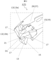
- FIG. 1 is a perspective view of a drill according to an embodiment of the present disclosure.
- FIG. 2 is an enlarged view of region II shown in FIG.
- FIG. 2 is a view of the drill shown in FIG. 1 as seen from the tip side.
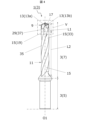
- FIG. 4 is a side view of the drill shown in FIG. 3 as viewed from a direction IV.
- FIG. 5 is an enlarged view of region V shown in FIG. 4 .
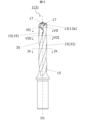
- FIG. 6 is a side view of the drill shown in FIG. 3 as viewed from a direction VI.
- 7 is a cross-sectional view taken along line VII-VII of the drill shown in FIG. 6.
- 8 is a cross-sectional view of the drill taken along line VIII-VIII in FIG. 6.
- FIG. 9 is a cross-sectional view taken along line IX-IX of the drill shown in FIG. 6. This is the same cross-sectional view as FIG. This is the same cross-sectional view as FIG.
- FIG. 2 is a schematic diagram showing a step of a manufacturing method of a machined product according to an embodiment of the present disclosure.
- FIG. 2 is a schematic diagram showing a step of a manufacturing method of a machined product according to an embodiment of the present disclosure.
- FIG. 2 is a schematic diagram showing a step of a manufacturing method of a machined product according to an embodiment of the present disclosure.
- each of the drawings referred to below shows a simplified view of only the main components of the embodiment that are necessary to explain the present invention. Therefore, the drill of the present disclosure may include any component not shown in each of the drawings referred to in this specification. Furthermore, the dimensions of the components in each drawing do not faithfully represent the actual dimensions of the components or the dimensional ratios of each component.
- chips generated at the tip of the drill are sent from the tip to the rear end through the discharge groove, and are discharged to the outside at the rear end part of the discharge groove.
- attention is only paid to simply improving the chip discharge performance.
- the chips will fly out to the outside before being sent to the rear end part of the discharge groove. This can cause damage to the inner surface of the drilled hole.
- One aspect of the present disclosure aims to provide a drill that improves chip removal while minimizing the impact on the inner surface of the drilled hole.
- FIG. 1 is a perspective view showing a drill according to an embodiment of the present disclosure.
- Figure 2 is an enlarged view of region II shown in Figure 1.
- Figure 3 is a front view of the insert shown in Figure 2 as viewed from the tip side.
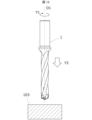
- a drill 1 has a rod-shaped body 3 that is rotatable around a rotation axis O1.
- the body 3 extends from the tip 3a to the rear end 3b along the rotation axis O1.
- the body 3 has a gripping portion 5 called a shank that is gripped by a rotating spindle of a machine tool or the like, and a cutting portion 7 called a body that is located on the tip 3a side of the gripping portion 5.
- the gripping portion 5 is a portion that is designed according to the shape of the spindle, etc., in the machine tool.
- the cutting portion 7 is a portion that comes into contact with the workpiece, and is a portion that plays a major role in cutting the workpiece.
- the arrow Y1 shown in Figure 1 indicates the rotation direction Y1 of the drill 1 (main body 3).
- the portion of the cutting portion 7 on the side of the tip 3a is detachable from the portion on the side of the rear end 3b.
- the portion of the body 3 on the side of the tip 3a is called the insert 9
- the portion of the body 3 on the side of the rear end 3b is called the holder 11.
- the body 3 is not configured as described above but is configured from a single member, that is, has a configuration generally known as a solid drill.
- the drill 1 having a body 3 with an insert 9 attached to a holder 11 will be described in detail below.
- the body 3, cutting portion 7, and insert 9 may be interchanged as long as there is no contradiction.
- the configuration (technical concept) of the body 3 having the insert 9 described below can also be applied to a body 3 (or cutting portion 7) having the configuration of a solid drill.
- the reference symbol for the body 3 is shown alongside the drill 1.
- the main body 3 (cutting portion 7 or insert 9) has a cutting edge 13 located at the tip 3a and a discharge groove 15 extending from the cutting edge 13.
- the main body 3 also has a clearance surface 17 located at the tip 3a.
- the cutting edge 13 is located at the front edge of the clearance surface 17 in the rotational direction Y1. In other words, the clearance surface 17 extends from the cutting edge 13 toward the rear in the rotational direction Y1 (the opposite side to the rotational direction Y1).
- flanks 17, cutting edges 13, and discharge grooves 15 is not limited to a specific number.
- the cutting portion 7 has three flanks 17, three cutting edges 13, and three discharge grooves 15, which is a so-called triple-blade drill configuration.
- the cutting portion 7 has two flanks 17, two cutting edges 13, and two discharge grooves 15, which is a so-called double-blade drill configuration.
- the multiple clearance faces 17, cutting edges 13, and discharge grooves 15 may each be positioned in a rotationally symmetrical relationship about the rotation axis O1.
- the three clearance faces 17 are positioned to have 120° rotational symmetry.
- the three cutting edges 13 are positioned to have 120° rotational symmetry, and the three discharge grooves 15 are positioned to have 120° rotational symmetry.
- the three flanks 17 are configured with rotational symmetry, attention will be given to one of the three flanks 17, and a detailed description of the other two flanks 17 will be omitted.
- the three cutting edges 13 and the three discharge grooves 15 are each configured with rotational symmetry, attention will be given to one of the three cutting edges 13 and one of the three discharge grooves 15.
- the cutting edge 13 and discharge groove 15 of interest will be referred to as the first cutting edge 13a and the first discharge groove 19. There is no problem with the other two cutting edges 13 and two discharge grooves 15 having the configuration described below.
- the first cutting edge 13a is located at the tip 3a of the main body 3, and when the main body 3 is viewed from the tip 3a side, in other words when viewed from the tip, it extends from the rotation axis O1 toward the outer periphery.
- the cutting edge 13 is located at the intersection of the clearance 17 and the rake face.
- the cutting edge 13 is formed by the intersection of multiple clearance faces 17 corresponding to the multiple cutting edges 13.
- Such a portion is called the chisel edge 21.
- the portion of the first cutting edge 13a that is located near the rotation axis O1 is the chisel edge 21.
- Figure 4 is a side view of the drill shown in Figure 2 as viewed from the IV direction.
- Figure 5 is an enlarged view of region V shown in Figure 4.
- Figure 6 is a side view of the drill shown in Figure 2 as viewed from the VI direction.
- Figure 7 is a cross-sectional view of the drill shown in Figure 6 taken along line VII-VII.
- Figure 8 is a cross-sectional view of the drill shown in Figure 6 taken along line VIII-VIII.
- Figure 9 is a cross-sectional view of the drill shown in Figure 6 taken along line IX-IX.
- Figure 10 is the same cross-sectional view as Figure 7.
- Figure 11 is the same cross-sectional view as Figure 8.
- the first discharge groove 19 of the cutting portion 7 extends from the first cutting edge 13a toward the rear end 3b.
- the first discharge groove 19 is a portion used to discharge chips generated by the first cutting edge 13a to the outside.
- the first discharge groove 19 does not need to extend to the rear end 3b of the main body 3.
- the first discharge groove 19 may be formed only in the cutting portion 7 and not in the gripping portion 5.
- the first discharge groove 19 may extend in a spiral shape around the rotation axis O1, as shown in the non-limiting example in Figure 1.
- the first discharge groove 19 has a first portion 23 located on the tip 3a side, and a second portion 25 located on the rear end 3b side of the first portion 23.
- the first portion 23 may include a groove extending from the rake face located along the outer peripheral portion of the first cutting edge 13a of the insert 9 toward the rear end 3b, and a groove located on the tip 3a side of the holder 11.
- the front end 27, outer portion 29, return end 31, and return amount ⁇ for the first discharge groove 19 are defined as follows:
- the front end 27 is the end of the first discharge groove 19 located most forward in the rotation direction Y1 of the rotation axis O1 in the above cross section S.
- the front end 27 is specified for each cross section. Specifically, in each cross section, the front end 27 is the point of contact when a tangent is drawn from the center point corresponding to the rotation axis O1 to the concave curve corresponding to the surface of the first discharge groove 19.
- the outer portion 29 is the portion of the first discharge groove 19 extending from the front end 27 to the heel end 32 (see Figures 7 and 8) in the above cross section S. At least a portion of the outer portion 29 is formed to be positioned rearward in the direction of rotation Y1 as it extends from the front end 27 toward the outer periphery, and is configured as what is known as a "turned portion (hooking portion)."
- the "heel side end 32" mentioned above means the end of the first discharge groove 19 that forms the opening, located forward in the rotational direction Y1, in the above cross section S.
- the part where the first discharge groove 19 and the outer circumferential surface of the body 3 intersect is the edge (rim) of the opening formed by the first discharge groove 19.
- the opening of the first discharge groove 19 has two edges, one located in front of the rotational direction Y1 and the other located in the rear of the rotational direction Y1. Of the two edges of the opening in the cross section S above, the one located in front of the rotational direction Y1 is the "heel side end 32."
- the return end 31 is the end of the outer portion 29 located furthest to the rear in the rotation direction Y1 in the cross section S.
- the return amount ⁇ is the angle between an imaginary line connecting the rotation axis O1 and the front end 27 and an imaginary line connecting the rotation axis O1 and the return end 31.
- the return amount ⁇ 1 in the first portion 23 may be greater than the return amount ⁇ 2 in the second portion 25.
- the front end 27, outer portion 29, and barb end 31 are each specified as part of the holder 11.
- the outer portion 29 can act as a barrier to prevent chips from flying out when they attempt to fly out to the outside. This makes it difficult for chips to fly out inadvertently, and reduces the impact of chips on the inner surface of the machined hole.
- the chips flow immediately after they are generated by the first cutting edge 13a, and so the flow of the chips is prone to become unstable, but the return amount ⁇ 1 in this first portion 23 is relatively large. This makes it possible to prevent the chips from accidentally flying out.
- the chips are prone to curl due to the outer portion 29. This makes it easy for the chips to gather together and be sent through the first discharge groove 19 from the tip 3a side to the rear end 3b side.
- the chips are easily discharged to the outside on the rear end 3b side. In this way, when the amount of return ⁇ 1 in the first portion 23 is greater than the amount of return ⁇ 2 in the second portion 25, the chips are more easily discharged while minimizing the impact on the inner surface of the machined hole.
- the amount of return ⁇ 2 in the second portion 25 may be 0, i.e., the outer portion 29 may not be formed in the second portion 25.
- the heel side end 32 in the second portion 25 may be located at the frontmost position in the rotational direction Y1 in the second portion 25.
- the return amount ⁇ ( ⁇ 1, ⁇ 2) can be measured in each of the cross section S1 of the first portion 23 perpendicular to the rotation axis O1 (for example, the cross section shown in FIG. 7) and the cross section S2 of the second portion 25 perpendicular to the rotation axis O1 (for example, the cross section shown in FIG. 8), and the magnitudes of these return amounts ⁇ 1 and ⁇ 2 can be compared.
- the return amounts ⁇ 1 and ⁇ 2 are not limited to specific values.
- the return amount ⁇ 1 can be set to 10° to 30°.
- the return amount ⁇ 2 can be set to 0° to 20°.
- the first portion 23 is located closer to the tip 3a than the second portion 25, but the first portion 23 may include the end of the first discharge groove 19 on the tip 3a side.
- the outer portion 29 of the first portion 23 tends to prevent the chips from accidentally flying out soon after they are generated by the first cutting edge 13a.
- the distance between the two intersections (the two edges of the opening in the cross section S described above) where the first discharge groove 19 and the outer peripheral surface of the body 3 intersect is defined as the opening width W1 of the first portion 23 (see FIG. 10).
- the distance between the two intersections where the first discharge groove 19 and the outer peripheral surface of the body 3 intersect is defined as the opening width W2 of the second portion 25 (see FIG. 11).
- the opening width W1 may be smaller than the opening width W2. If the opening width W1 in the first portion 23 is relatively small, the chips are less likely to accidentally fly out of the first portion 23. Also, if the opening width W2 in the second portion 25 is relatively large, the chips are more likely to be discharged to the outside on the side of the rear end 3b in the second portion 25.
- the outer portion 29 of the second portion 25 of the first discharge groove 19 may include a return portion 29a, which is the portion from the front end 27 to the return end 31, and an inclined surface portion 29b, which is the portion from the return end 31 to the heel side end 32.
- the return portion 29a may be a concave curved shape
- the inclined surface portion 29b may be a straight shape.
- the heel side end 32 may be located further forward in the rotational direction Y1 than the return end 31.
- the cutting portion 7 in the non-limiting example shown in Figure 1 has multiple (specifically, three) clearance surfaces 17, cutting edges 13, and discharge grooves 15.
- the cutting edge 13 located forward of the first cutting edge 13a in the rotational direction Y1 is the second cutting edge 13b
- the discharge groove 15 extending from this second cutting edge 13b toward the rear end 3b is the second discharge groove 33
- the area of the outer circumferential surface of the cutting portion 7 located between the first discharge groove 19 and the second discharge groove 33 is the first outer circumferential surface 35.
- the area of the first outer peripheral surface 35 located between the first portion 23 and the second discharge groove 33 is referred to as the first region 35a, and the area of the first outer peripheral surface 35 located between the second portion 25 and the second discharge groove 33 is referred to as the second region 35b.
- the first outer peripheral surface 35 has the first region 35a adjacent to the first portion 23 and the second region 35b adjacent to the second portion 25.
- the first region 35a may have a protrusion 37 that protrudes rearward in the rotational direction Y1.
- the first discharge groove 19 and the ridge of the first outer surface 35 may have a portion located on the side of the tip 3a that protrudes rearward in the rotational direction Y1.
- This protrusion 37 may form the outer portion 29 of the first portion 23 described above.
- the outer portion 29 is configured in this manner, for example, the area excluding the outer portion 29 in the first portion 23 and the area excluding the outer portion 29 in the second portion 25 can be easily configured similarly to each other. This makes it easier for chips to flow smoothly from the first portion 23 to the second portion 25.
- the length (of the curve) from the front end point to the rear end point (corresponding to the return end 31 or the heel end 32) of the first region 35a in the rotational direction Y1 is defined as W3 (see FIG. 10).
- the length (of the curve) from the front end point to the rear end point (corresponding to the heel end 32) of the second region 35b in the rotational direction Y1 is defined as W4 (see FIG. 11).
- the length W3 may be greater than the length W4.
- the length W3 of the first region 35a may be greater than the length W4 of the second region 35b by the amount of the protrusion 37 that protrudes rearward in the rotational direction Y1.
- the length L1 of the first portion 23 in the direction along the rotation axis O1 may be greater than the length L2 of the second portion 25 in the direction along the rotation axis O1, or may be less than the length L2 of the second portion 25, as in the non-limiting example shown in FIG. 4.
- the length L1 of the first portion 23 is less than the length L2 of the second portion 25, the degree of freedom in machining the drill 1 is increased.
- the flow of chips generated by the cutting edge 13 tends to become unstable immediately after the chips are generated by the cutting edge 13. Therefore, it is not necessary to set the length L1 of the first portion 23 excessively large.
- the outer portion 29 of the second portion 25 is smaller than that of the first portion 23, it is easier to ensure a larger space in the cross section S (S1, S2) perpendicular to the rotation axis O1 in the second portion 25 than in the first portion 23. Therefore, it is possible to reduce the risk of chip clogging while suppressing the inadvertent ejection of chips.
- a virtual circle of an arbitrary radius is assumed to be centered on the rotation axis O1.
- a partially open space formed by being partially surrounded by the first discharge groove 19, or by being partially surrounded by the first discharge groove 19 and the surface of the shaft portion of the insert 9, is referred to as a groove space.
- the groove width W is the groove width of the groove space at the depth position corresponding to the radius of the virtual circle.
- the groove space in a conventional drill may have a shape in which the groove width increases monotonically from the groove bottom (the part close to the rotation axis) to the edge of the opening (the part connected to the outer periphery) in a cross section perpendicular to the rotation axis.
- the first portion 23 in the cross section S1 of the first discharge groove 19 perpendicular to the rotation axis O1, the first portion 23 may have a narrowed portion 23a in which the groove width W decreases with increasing distance from the rotation axis O1.
- the first portion 23 may have a narrowed portion 23a in which the opening (the groove space) narrows with increasing distance from the rotation axis O1.
- the narrowed portion 23a may be located on the front side and the rear side in the rotational direction Y1 in the first portion 23.
- the narrowed portion 23a located on the front side in the rotational direction Y1 may be a part of the outer portion 29.
- the second portion 25 may not have such a narrowed portion 23a. That is, the groove width W of the second portion 25 may monotonically increase in the cross section S2 as it moves away from the rotation axis O1. In this case, good chip discharge performance is ensured in the second portion 25, so chip clogging is less likely to occur.
- the outer diameter of the cutting portion 7 is set to 6 mm to 42.5 mm.
- L is set to 1D to 12D.
- the material of the main body 3 may be, for example, cemented carbide or cermet.
- the composition of the cemented carbide may be, for example, WC-Co, WC-TiC-Co, or WC-TiC-TaC-Co.
- WC, TiC, and TaC may be hard particles
- Co may be a binder phase.
- the cermet may be a sintered composite material in which a ceramic component is combined with a metal.
- An example of a cermet is a titanium compound whose main component is titanium carbide (TiC) or titanium nitride (TiN). It goes without saying that the material of the main body 3 is not limited to the above composition.
- the surface of the body 3 may be coated with a coating using a chemical vapor deposition (CVD) method or a physical vapor deposition ( PVD ) method.
- the composition of the coating may include, for example, titanium carbide (TiC), titanium nitride (TiN), titanium carbonitride (TiCN), and alumina ( Al2O3 ).
- the material of the holder 11 may be, for example, aluminum, carbon steel, alloy steel, stainless steel, cast iron, and non-ferrous metals.
- the machined product 101 may be produced by cutting a workpiece 103.
- the manufacturing method of the machined product 101 may include the following steps (1) to (4).
- steps (1) and (2) may be performed, for example, by fixing the workpiece 103 on the table of a machine tool to which the drill 1 is attached, and bringing the drill 1 closer to the workpiece 103 while rotating. Note that in step (2), it is sufficient that the workpiece 103 and the drill 1 are relatively close to each other, and for example, the workpiece 103 may be brought closer to the drill 1.
- cutting may be performed so that at least a portion of the cutting portion 7 in the main body 3 is located inside the machining hole 105.
- the gripping portion 5 in the main body 3 may be set to be located outside the machining hole 105.
- a portion of the cutting portion 7 on the rear end 3b side may be set to be located outside the machining hole 105.
- the above-mentioned portion can function as a margin area for chip discharge, and excellent chip discharge properties can be achieved through this area.
- step (4) similarly to the above-mentioned step (2), the workpiece 103 and the drill 1 only need to be separated from each other; for example, the workpiece 103 may be separated from the drill 1.
- the process of contacting the cutting edge 13 of the drill 1 with different locations on the workpiece 103 while keeping the drill 1 rotating may be repeated.
- Examples of the material of the workpiece 103 include aluminum, carbon steel, alloy steel, stainless steel, cast iron, and non-ferrous metals.
- the drill in the first aspect of the present disclosure has a rod-shaped body that can rotate around a rotation axis and extends from a front end to a rear end along the rotation axis.
- the body has a first cutting edge located at the front end and a first discharge groove extending from the first cutting edge.
- the first discharge groove has a first portion located on the front end side and a second portion located on the rear end side of the first portion.
- an end of the first discharge groove located most forward in the rotation direction of the rotation axis is a front end
- a portion of the first discharge groove from the front end to an end on a heel side (an edge of a pair of edges located forward in the rotation direction) is an outer portion
- an end of the outer portion located most rearward in the rotation direction is a return end
- an angle formed by a virtual line connecting the rotation axis and the front end and a virtual line connecting the rotation axis and the return end is a return amount
- the return amount in the first portion is greater than the return amount in the second portion.
- the drill in aspect 2 of the present disclosure is based on aspect 1, and has the following elements: in a cross section of the first portion perpendicular to the rotation axis, the distance between two intersections where the first discharge groove and the outer peripheral surface of the main body intersect is the opening width of the first portion; in a cross section of the second portion perpendicular to the rotation axis, the distance between two intersections where the first discharge groove and the outer peripheral surface of the main body intersect is the opening width of the second portion, and the opening width of the first portion is smaller than the opening width of the second portion.
- the drill in aspect 3 of the present disclosure is based on aspect 1 or 2, and the main body further has a second cutting edge located forward of the first cutting edge in the direction of rotation, a second discharge groove extending from the second cutting edge, and an outer peripheral surface located between the first discharge groove and the second discharge groove, the outer peripheral surface having a first region adjacent to the first portion and a second region adjacent to the second portion, and the first region has a convex portion that protrudes toward the rear in the direction of rotation.
- the drill in aspect 4 of the present disclosure is based on aspect 3, and has an element in which the length from the front end point to the rear end point of the first region in the direction of rotation in a cross section of the first portion perpendicular to the rotation axis is greater than the length from the front end point to the rear end point of the second region in the direction of rotation in a cross section of the second portion perpendicular to the rotation axis.
- the drill in aspect 5 of the present disclosure is based on any one of aspects 1 to 4, and has an element in which the length of the first portion in the direction along the rotation axis is smaller than the length of the second portion in the direction along the rotation axis.
- the drill in aspect 6 of the present disclosure is based on any one of aspects 1 to 5, and has an element in which the first portion has a narrowed portion in a cross section of the first portion perpendicular to the rotation axis, in which the groove width decreases with increasing distance from the rotation axis.
- the drill in aspect 7 of the present disclosure is based on aspect 6, and the second portion has an element in which the groove width increases with increasing distance from the rotation axis.
- the drill in aspect 8 of the present disclosure is based on any one of aspects 1 to 7, and has the following element: the first portion includes an end portion of the first discharge groove on the side of the tip.
- the method for manufacturing a machined product in aspect 9 of the present disclosure includes the steps of rotating a drill in any one of aspects 1 to 8 around the rotation axis, contacting the rotating drill with a workpiece, and removing the drill from the workpiece.
Landscapes
- Engineering & Computer Science (AREA)
- Mechanical Engineering (AREA)
- Drilling Tools (AREA)
Priority Applications (1)
| Application Number | Priority Date | Filing Date | Title |
|---|---|---|---|
| JP2025516544A JPWO2024224769A1 (https=) | 2023-04-26 | 2024-02-19 |
Applications Claiming Priority (2)
| Application Number | Priority Date | Filing Date | Title |
|---|---|---|---|
| JP2023072546 | 2023-04-26 | ||
| JP2023-072546 | 2023-04-26 |
Publications (1)
| Publication Number | Publication Date |
|---|---|
| WO2024224769A1 true WO2024224769A1 (ja) | 2024-10-31 |
Family
ID=93255988
Family Applications (1)
| Application Number | Title | Priority Date | Filing Date |
|---|---|---|---|
| PCT/JP2024/005717 Ceased WO2024224769A1 (ja) | 2023-04-26 | 2024-02-19 | ドリルおよび切削加工物の製造方法 |
Country Status (2)
| Country | Link |
|---|---|
| JP (1) | JPWO2024224769A1 (https=) |
| WO (1) | WO2024224769A1 (https=) |
Citations (3)
| Publication number | Priority date | Publication date | Assignee | Title |
|---|---|---|---|---|
| JPH03142118A (ja) * | 1989-10-27 | 1991-06-17 | Mitsubishi Materials Corp | 穴明け工具 |
| JPH09501109A (ja) * | 1993-08-06 | 1997-02-04 | ケンナメタル ヘルテル アクチェンゲゼルシャフト ウェルクツォイゲ ウント ハルトシュトッフェ | ツイストドリル |
| JP2004216468A (ja) * | 2003-01-09 | 2004-08-05 | Toshiba Tungaloy Co Ltd | ツイストドリル |
-
2024
- 2024-02-19 JP JP2025516544A patent/JPWO2024224769A1/ja active Pending
- 2024-02-19 WO PCT/JP2024/005717 patent/WO2024224769A1/ja not_active Ceased
Patent Citations (3)
| Publication number | Priority date | Publication date | Assignee | Title |
|---|---|---|---|---|
| JPH03142118A (ja) * | 1989-10-27 | 1991-06-17 | Mitsubishi Materials Corp | 穴明け工具 |
| JPH09501109A (ja) * | 1993-08-06 | 1997-02-04 | ケンナメタル ヘルテル アクチェンゲゼルシャフト ウェルクツォイゲ ウント ハルトシュトッフェ | ツイストドリル |
| JP2004216468A (ja) * | 2003-01-09 | 2004-08-05 | Toshiba Tungaloy Co Ltd | ツイストドリル |
Also Published As
| Publication number | Publication date |
|---|---|
| JPWO2024224769A1 (https=) | 2024-10-31 |
Similar Documents
| Publication | Publication Date | Title |
|---|---|---|
| JP6892503B2 (ja) | 回転工具 | |
| US20220055123A1 (en) | Cutting insert, rotary tool, and method for manufacturing machined product | |
| JP7386339B2 (ja) | ドリル及び切削加工物の製造方法 | |
| JP6941047B2 (ja) | 回転工具及び切削加工物の製造方法 | |
| JP7103933B2 (ja) | 切削インサート、回転工具及び切削加工物の製造方法 | |
| CN114144274B (zh) | 钻头以及切削加工物的制造方法 | |
| JP7344321B2 (ja) | 回転工具及び切削加工物の製造方法 | |
| WO2025204502A1 (ja) | ドリルおよび切削加工物の製造方法 | |
| JP7142681B2 (ja) | ドリル及び切削加工物の製造方法 | |
| JP6882517B2 (ja) | 回転工具 | |
| WO2024224769A1 (ja) | ドリルおよび切削加工物の製造方法 | |
| JP7499342B2 (ja) | 切削インサート、回転工具および切削加工物の製造方法 | |
| WO2018139584A1 (ja) | 切削インサート、ドリル及びそれを用いた切削加工物の製造方法 | |
| JP7750804B2 (ja) | ドリル及び切削加工物の製造方法 | |
| JP7279163B2 (ja) | 回転工具及び切削加工物の製造方法 | |
| CN114786850B (zh) | 钻头以及切削加工物的制造方法 | |
| WO2024224768A1 (ja) | ドリルおよび切削加工物の製造方法 | |
| WO2023162671A1 (ja) | ドリル及び切削加工物の製造方法 | |
| JP6875518B2 (ja) | ドリル及び切削加工物の製造方法 | |
| WO2026088668A1 (ja) | ドリル、及び切削加工物の製造方法 | |
| WO2025182277A1 (ja) | 回転工具、及び切削加工物の製造方法 | |
| JPWO2023162671A5 (https=) | ||
| WO2025197320A1 (ja) | ドリル及び切削加工物の製造方法 | |
| JP2020069558A (ja) | 回転工具及び切削加工物の製造方法 |
Legal Events
| Date | Code | Title | Description |
|---|---|---|---|
| 121 | Ep: the epo has been informed by wipo that ep was designated in this application |
Ref document number: 24796528 Country of ref document: EP Kind code of ref document: A1 |
|
| ENP | Entry into the national phase |
Ref document number: 2025516544 Country of ref document: JP Kind code of ref document: A |
|
| WWE | Wipo information: entry into national phase |
Ref document number: 2025516544 Country of ref document: JP |
|
| NENP | Non-entry into the national phase |
Ref country code: DE |
|
| 122 | Ep: pct application non-entry in european phase |
Ref document number: 24796528 Country of ref document: EP Kind code of ref document: A1 |