WO2024224513A1 - 熱交換器及び空気調和装置 - Google Patents
熱交換器及び空気調和装置 Download PDFInfo
- Publication number
- WO2024224513A1 WO2024224513A1 PCT/JP2023/016467 JP2023016467W WO2024224513A1 WO 2024224513 A1 WO2024224513 A1 WO 2024224513A1 JP 2023016467 W JP2023016467 W JP 2023016467W WO 2024224513 A1 WO2024224513 A1 WO 2024224513A1
- Authority
- WO
- WIPO (PCT)
- Prior art keywords
- heat transfer
- header
- transfer tubes
- refrigerant
- heat exchanger
- Prior art date
- Legal status (The legal status is an assumption and is not a legal conclusion. Google has not performed a legal analysis and makes no representation as to the accuracy of the status listed.)
- Ceased
Links
Images







Classifications
-
- F—MECHANICAL ENGINEERING; LIGHTING; HEATING; WEAPONS; BLASTING
- F28—HEAT EXCHANGE IN GENERAL
- F28D—HEAT-EXCHANGE APPARATUS, NOT PROVIDED FOR IN ANOTHER SUBCLASS, IN WHICH THE HEAT-EXCHANGE MEDIA DO NOT COME INTO DIRECT CONTACT
- F28D1/00—Heat-exchange apparatus having stationary conduit assemblies for one heat-exchange medium only, the media being in contact with different sides of the conduit wall, in which the other heat-exchange medium is a large body of fluid, e.g. domestic or motor car radiators
- F28D1/02—Heat-exchange apparatus having stationary conduit assemblies for one heat-exchange medium only, the media being in contact with different sides of the conduit wall, in which the other heat-exchange medium is a large body of fluid, e.g. domestic or motor car radiators with heat-exchange conduits immersed in the body of fluid
- F28D1/04—Heat-exchange apparatus having stationary conduit assemblies for one heat-exchange medium only, the media being in contact with different sides of the conduit wall, in which the other heat-exchange medium is a large body of fluid, e.g. domestic or motor car radiators with heat-exchange conduits immersed in the body of fluid with tubular conduits
- F28D1/053—Heat-exchange apparatus having stationary conduit assemblies for one heat-exchange medium only, the media being in contact with different sides of the conduit wall, in which the other heat-exchange medium is a large body of fluid, e.g. domestic or motor car radiators with heat-exchange conduits immersed in the body of fluid with tubular conduits the conduits being straight
- F28D1/0535—Heat-exchange apparatus having stationary conduit assemblies for one heat-exchange medium only, the media being in contact with different sides of the conduit wall, in which the other heat-exchange medium is a large body of fluid, e.g. domestic or motor car radiators with heat-exchange conduits immersed in the body of fluid with tubular conduits the conduits being straight the conduits having a non-circular cross-section
- F28D1/05358—Assemblies of conduits connected side by side or with individual headers, e.g. section type radiators
-
- F—MECHANICAL ENGINEERING; LIGHTING; HEATING; WEAPONS; BLASTING
- F25—REFRIGERATION OR COOLING; COMBINED HEATING AND REFRIGERATION SYSTEMS; HEAT PUMP SYSTEMS; MANUFACTURE OR STORAGE OF ICE; LIQUEFACTION SOLIDIFICATION OF GASES
- F25B—REFRIGERATION MACHINES, PLANTS OR SYSTEMS; COMBINED HEATING AND REFRIGERATION SYSTEMS; HEAT PUMP SYSTEMS
- F25B39/00—Evaporators; Condensers
- F25B39/02—Evaporators
-
- F—MECHANICAL ENGINEERING; LIGHTING; HEATING; WEAPONS; BLASTING
- F25—REFRIGERATION OR COOLING; COMBINED HEATING AND REFRIGERATION SYSTEMS; HEAT PUMP SYSTEMS; MANUFACTURE OR STORAGE OF ICE; LIQUEFACTION SOLIDIFICATION OF GASES
- F25B—REFRIGERATION MACHINES, PLANTS OR SYSTEMS; COMBINED HEATING AND REFRIGERATION SYSTEMS; HEAT PUMP SYSTEMS
- F25B39/00—Evaporators; Condensers
- F25B39/04—Condensers
-
- F—MECHANICAL ENGINEERING; LIGHTING; HEATING; WEAPONS; BLASTING
- F28—HEAT EXCHANGE IN GENERAL
- F28F—DETAILS OF HEAT-EXCHANGE AND HEAT-TRANSFER APPARATUS, OF GENERAL APPLICATION
- F28F1/00—Tubular elements; Assemblies of tubular elements
- F28F1/02—Tubular elements of cross-section which is non-circular
- F28F1/022—Tubular elements of cross-section which is non-circular with multiple channels
-
- F—MECHANICAL ENGINEERING; LIGHTING; HEATING; WEAPONS; BLASTING
- F28—HEAT EXCHANGE IN GENERAL
- F28F—DETAILS OF HEAT-EXCHANGE AND HEAT-TRANSFER APPARATUS, OF GENERAL APPLICATION
- F28F9/00—Casings; Header boxes; Auxiliary supports for elements; Auxiliary members within casings
- F28F9/02—Header boxes; End plates
- F28F9/0219—Arrangements for sealing end plates into casing or header box; Header box sub-elements
- F28F9/0221—Header boxes or end plates formed by stacked elements
-
- F—MECHANICAL ENGINEERING; LIGHTING; HEATING; WEAPONS; BLASTING
- F25—REFRIGERATION OR COOLING; COMBINED HEATING AND REFRIGERATION SYSTEMS; HEAT PUMP SYSTEMS; MANUFACTURE OR STORAGE OF ICE; LIQUEFACTION SOLIDIFICATION OF GASES
- F25B—REFRIGERATION MACHINES, PLANTS OR SYSTEMS; COMBINED HEATING AND REFRIGERATION SYSTEMS; HEAT PUMP SYSTEMS
- F25B13/00—Compression machines, plants or systems, with reversible cycle
-
- F—MECHANICAL ENGINEERING; LIGHTING; HEATING; WEAPONS; BLASTING
- F28—HEAT EXCHANGE IN GENERAL
- F28D—HEAT-EXCHANGE APPARATUS, NOT PROVIDED FOR IN ANOTHER SUBCLASS, IN WHICH THE HEAT-EXCHANGE MEDIA DO NOT COME INTO DIRECT CONTACT
- F28D1/00—Heat-exchange apparatus having stationary conduit assemblies for one heat-exchange medium only, the media being in contact with different sides of the conduit wall, in which the other heat-exchange medium is a large body of fluid, e.g. domestic or motor car radiators
- F28D1/02—Heat-exchange apparatus having stationary conduit assemblies for one heat-exchange medium only, the media being in contact with different sides of the conduit wall, in which the other heat-exchange medium is a large body of fluid, e.g. domestic or motor car radiators with heat-exchange conduits immersed in the body of fluid
- F28D1/03—Heat-exchange apparatus having stationary conduit assemblies for one heat-exchange medium only, the media being in contact with different sides of the conduit wall, in which the other heat-exchange medium is a large body of fluid, e.g. domestic or motor car radiators with heat-exchange conduits immersed in the body of fluid with plate-like or laminated conduits
- F28D1/0308—Heat-exchange apparatus having stationary conduit assemblies for one heat-exchange medium only, the media being in contact with different sides of the conduit wall, in which the other heat-exchange medium is a large body of fluid, e.g. domestic or motor car radiators with heat-exchange conduits immersed in the body of fluid with plate-like or laminated conduits the conduits being formed by paired plates touching each other
- F28D1/035—Heat-exchange apparatus having stationary conduit assemblies for one heat-exchange medium only, the media being in contact with different sides of the conduit wall, in which the other heat-exchange medium is a large body of fluid, e.g. domestic or motor car radiators with heat-exchange conduits immersed in the body of fluid with plate-like or laminated conduits the conduits being formed by paired plates touching each other with U-flow or serpentine-flow inside the conduits
-
- F—MECHANICAL ENGINEERING; LIGHTING; HEATING; WEAPONS; BLASTING
- F28—HEAT EXCHANGE IN GENERAL
- F28D—HEAT-EXCHANGE APPARATUS, NOT PROVIDED FOR IN ANOTHER SUBCLASS, IN WHICH THE HEAT-EXCHANGE MEDIA DO NOT COME INTO DIRECT CONTACT
- F28D1/00—Heat-exchange apparatus having stationary conduit assemblies for one heat-exchange medium only, the media being in contact with different sides of the conduit wall, in which the other heat-exchange medium is a large body of fluid, e.g. domestic or motor car radiators
- F28D1/02—Heat-exchange apparatus having stationary conduit assemblies for one heat-exchange medium only, the media being in contact with different sides of the conduit wall, in which the other heat-exchange medium is a large body of fluid, e.g. domestic or motor car radiators with heat-exchange conduits immersed in the body of fluid
- F28D1/03—Heat-exchange apparatus having stationary conduit assemblies for one heat-exchange medium only, the media being in contact with different sides of the conduit wall, in which the other heat-exchange medium is a large body of fluid, e.g. domestic or motor car radiators with heat-exchange conduits immersed in the body of fluid with plate-like or laminated conduits
- F28D1/0366—Heat-exchange apparatus having stationary conduit assemblies for one heat-exchange medium only, the media being in contact with different sides of the conduit wall, in which the other heat-exchange medium is a large body of fluid, e.g. domestic or motor car radiators with heat-exchange conduits immersed in the body of fluid with plate-like or laminated conduits the conduits being formed by spaced plates with inserted elements
- F28D1/0383—Heat-exchange apparatus having stationary conduit assemblies for one heat-exchange medium only, the media being in contact with different sides of the conduit wall, in which the other heat-exchange medium is a large body of fluid, e.g. domestic or motor car radiators with heat-exchange conduits immersed in the body of fluid with plate-like or laminated conduits the conduits being formed by spaced plates with inserted elements with U-flow or serpentine-flow inside the conduits
-
- F—MECHANICAL ENGINEERING; LIGHTING; HEATING; WEAPONS; BLASTING
- F28—HEAT EXCHANGE IN GENERAL
- F28F—DETAILS OF HEAT-EXCHANGE AND HEAT-TRANSFER APPARATUS, OF GENERAL APPLICATION
- F28F2220/00—Closure means, e.g. end caps on header boxes or plugs on conduits
-
- F—MECHANICAL ENGINEERING; LIGHTING; HEATING; WEAPONS; BLASTING
- F28—HEAT EXCHANGE IN GENERAL
- F28F—DETAILS OF HEAT-EXCHANGE AND HEAT-TRANSFER APPARATUS, OF GENERAL APPLICATION
- F28F2230/00—Sealing means
Definitions
- This disclosure relates to a heat exchanger and an air conditioning device equipped with this heat exchanger.
- the present disclosure is intended to solve the problems described above, and aims to provide a heat exchanger and air conditioner that reduces head difference and suppresses liquid retention.
- the heat exchanger includes a plurality of heat transfer tubes arranged in a first direction, each extending in a second direction intersecting the first direction, with both ends in the second direction sealed and through which a refrigerant flows, each of the plurality of heat transfer tubes has a plurality of through holes formed inside the both ends and connecting the internal space of each of the plurality of heat transfer tubes to the outside, the plurality of heat transfer tubes have a plurality of connecting parts that directly connect the multiple through holes of adjacent heat transfer tubes among the plurality of heat transfer tubes, or have a plurality of header tubes that are inserted into the multiple through holes and connect the multiple through holes of adjacent heat transfer tubes among the plurality of heat transfer tubes, the multiple connecting parts or the multiple header tubes are a plurality of header parts formed to extend in the first direction, which communicate the refrigerant with the internal spaces of each of the plurality of heat transfer tubes, and constitute a plurality of header parts that serve as inlets and outlets for the refrigerant of the heat transfer tube group composed of the plurality of
- the air conditioning device according to the present disclosure is equipped with the above-mentioned heat exchanger.
- the heat exchanger and air conditioning apparatus have multiple header sections formed by connecting multiple through holes by a connecting section or header pipe, and the multiple header sections are provided at positions that divide the multiple heat transfer tubes into upper and lower sections in the direction of gravity.
- the heat exchanger and air conditioning apparatus can shorten the distance that the refrigerant rises inside the heat transfer tubes, compared to when the multiple header sections are not provided at positions that divide the multiple heat transfer tubes into upper and lower sections in the direction of gravity.
- the heat exchanger and air conditioning apparatus can reduce head differences and suppress liquid stagnation by shortening the distance that the refrigerant rises, compared to when the multiple header sections are not provided at positions that divide the multiple heat transfer tubes into upper and lower sections in the direction of gravity.
- FIG. 1 is a perspective view showing a schematic configuration of a heat exchanger according to a first embodiment
- 1 is a vertical cross-sectional view of a heat exchanger according to a first embodiment of the present invention
- 2 is a view of a heat transfer tube of the heat exchanger according to the first embodiment viewed in a first direction.
- FIG. 4 is a conceptual diagram of a cross section of the heat transfer tube of FIG. 3 taken along line AA in the heat exchanger according to the first embodiment, as viewed in the direction of the arrows.
- FIG. 4 is a vertical cross-sectional view of a modified example of the heat exchanger according to the first embodiment.
- 1 is a refrigerant circuit diagram during cooling operation of an air-conditioning apparatus equipped with a heat exchanger according to a first embodiment.
- FIG. 11 is a perspective view showing a heat transfer tube of a heat exchanger according to a second embodiment.
- 5 is a conceptual diagram of a cross section of the heat transfer tube of FIG. 3 taken along line AA in a heat exchanger according to a second embodiment, as viewed in the direction of the arrows.
- 11 is a perspective view showing a part of the inner surface of a heat transfer tube of a heat exchanger according to a third embodiment.
- FIG. 11 is a conceptual diagram of a heat exchanger according to a fourth embodiment, viewed in a first direction.
- FIG. 13 is a conceptual diagram of a modified example of the heat exchanger according to the fourth embodiment, viewed in a first direction.
- FIG. 4 is a conceptual diagram of a heat exchanger according to a comparative example viewed in a first direction.
- FIG. 13 is a conceptual diagram of a heat exchanger according to embodiment 5 viewed in a first direction.
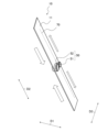
- FIG. 1 is a perspective view showing a schematic configuration of a heat exchanger 100 according to the first embodiment.
- the white arrows shown in Fig. 1 indicate an example of the direction in which the refrigerant flows.
- the configuration of the heat exchanger 100 will be described with reference to Fig. 1.
- the refrigerant direction shown by the white arrows below is an example, and the refrigerant flow direction may be opposite to that shown in the figure depending on the case in which the heat exchanger 100 functions as an evaporator or a condenser.
- a partition portion 70 provided inside the heat transfer tube 10 is indicated by a broken line.
- Heat exchanger 100 is a device that exchanges heat between the refrigerant flowing inside heat exchanger 100 and the fluid flowing outside heat exchanger 100. In the case of an air conditioning device, heat exchanger 100 exchanges heat between the refrigerant flowing inside heat exchanger 100 and the air flowing outside heat exchanger 100. Heat exchanger 100 is connected to other heat exchangers and compressors, etc. by refrigerant piping, and constitutes part of the various devices that make up the refrigerant circuit.
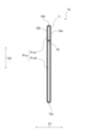
- FIG. 2 is a vertical cross-sectional view of the heat exchanger 100 according to the first embodiment.
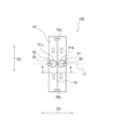
- FIG. 3 is a view of the heat transfer tube 10 of the heat exchanger 100 according to the first embodiment as viewed in the first direction D1.
- FIG. 4 is a conceptual diagram of the heat exchanger 100 according to the first embodiment as viewed in the direction of the arrows at the cross section of the heat transfer tube 10 at line A-A in FIG. 3.
- the cross-sectional view shown in FIG. 2 shows the cross section of the heat exchanger 100 in a plane along the first direction D1 and the second direction D2.
- FIG. 2 also shows a part of the heat exchanger 100.
- the partition 70 provided inside the heat transfer tube 10 is shown by a dashed line.
- the structure of the heat exchanger 100 will be described in detail below with reference to FIGS. 1 to 4.
- the heat exchanger 100 is arranged in a first direction D1, and includes a plurality of heat transfer tubes 10 each extending in a second direction D2 intersecting the first direction D1, both ends of which are sealed in the second direction D2, through which a refrigerant flows in the second direction D2.
- the heat exchanger 100 has a plurality of heat transfer tubes 10 arranged in a first direction D1 and connected to each other.
- the heat transfer tubes 10 are flat tubes that extend in a direction in which a tube axis Ax extends (hereinafter also referred to as a tube axis direction) and have a flat shape that is long in one direction in a cross section perpendicular to the tube axis Ax.
- the heat transfer tubes 10 are preferably flat tubes, but are not limited to flat tubes.
- the first direction D1 in which the multiple heat transfer tubes 10 are arranged is referred to as the arrangement direction
- the axial direction of the heat transfer tubes 10 is referred to as the second direction D2 or the longitudinal direction of the heat transfer tubes 10
- the longitudinal direction of the cross section of the heat transfer tubes 10 is referred to as the third direction D3 or the short side direction of the heat transfer tubes 10.
- the third direction D3 is a direction perpendicular to the first direction D1 and the second direction D2.
- the heat exchanger 100 is defined as being installed so that the arrangement direction (first direction D1) of the heat transfer tubes 10 is the left-right direction, as shown in Figure 1.
- Each heat transfer tube 10 is defined as being arranged so that its tube axis Ax is the up-down direction perpendicular to the arrangement direction (first direction D1) and its short side direction (third direction D3) is the front-rear direction perpendicular to the tube axis direction and the arrangement direction.
- the arrangement of the heat exchanger 100, or the angle between the arrangement direction (first direction D1) of the heat transfer tubes 10 in the heat exchanger 100 and the tube axis direction (second direction D2) of each heat transfer tube 10, is not limited to the above case.
- the heat exchanger 100 may be arranged at an angle so that the tube axis direction of each heat transfer tube 10 is inclined with respect to the vertical direction.
- the heat exchanger 100 when the heat exchanger 100 is installed so that the arrangement direction (first direction D1) of the heat transfer tubes 10 is the left-right direction, the heat exchanger 100 may be configured so that the tube axis direction of each heat transfer tube 10 is inclined with respect to the vertical direction.
- Gaps that are air flow paths P2 are formed between the tube walls 11 of adjacent heat transfer tubes 10 in the arrangement direction of the heat transfer tubes 10 (first direction D1), and air flows through each gap in the heat exchanger 100 along the short side direction of the heat transfer tube 10 (third direction D3).
- the fluid that flows through the heat transfer tube 10 is a refrigerant.
- a heat transfer flow path P1a through which the refrigerant flows is provided inside the heat transfer tube 10.
- the fluid that flows through the heat transfer tube 10 may be other fluids such as water or brine instead of a refrigerant.
- the heat exchanger 100 has tube sealing portions 20 that close each open end 10e on both sides in the longitudinal direction (second direction D2) of the heat transfer tubes 10.
- the tube sealing portions 20 are provided for each heat transfer tube 10 at two locations, on the upper and lower sides of the flat tube.
- the tube sealing portions 20 are joined to the open end 10e of the heat transfer tube 10 by a joining means such as brazing or adhesive, for example.
- each of the heat transfer tubes 10 has a tube wall 11 in which a heat transfer flow path P1a is provided, through which the refrigerant flows in the internal space.
- the heat transfer tube 10 has a tube structure that maintains an internal space through which the refrigerant flows along its longitudinal direction (second direction D2), i.e., from the upper end to the lower end of the tube wall 11.
- the tube wall 11 of the heat transfer tube 10 has substantially flat tube side wall portions 10a and 10b that face each other in the first direction D1.
- the tube wall 11 of the heat transfer tube 10 also has curved connecting wall portions 10c and 10d that connect the tube side wall portions 10a and 10b at each end on both sides of the tube side wall portions 10a and 10b in the third direction D3.
- the tube side wall portions 10a and 10b may be referred to as the tube side wall portions 10a, etc.
- the tube side wall 10a and the tube side wall 10b each have a rectangular shape with a long side extending in the longitudinal direction (second direction D2) of the heat transfer tube 10 and a short side extending in the lateral direction (third direction D3) of the heat transfer tube 10.
- the tube side wall 10a and the tube side wall 10b are each flat, but the "flat" in this application does not have to be a completely flat surface, and may have a structure that appears to spread out in a plane as a whole.
- the tube side wall 10a and the tube side wall 10b may have a depression, protrusion, or wave shape formed in a part of the area that spreads out in a plane.
- the wall on the left side of the tube wall 11 is the tube side wall 10a, and the wall on the right side of the tube wall 11 is the tube side wall 10b. If the heat transfer tube 10 is a circular tube, the tube wall 11 is formed in a cylindrical shape.
- each of the heat transfer tubes 10 has a plurality of through holes 30 formed inward from both ends in the second direction D2, which connect the internal space of each of the heat transfer tubes 10 to the outside.
- a through hole 30 is formed in the tube side wall portion 10a and the tube side wall portion 10b.
- a through hole 30a that penetrates in the first direction D1 is formed in the left tube side wall portion 10a, and a through hole 30b that penetrates in the first direction D1 is formed in the right tube side wall portion 10b.
- Through holes 30a and 30b are through holes that constitute the first header section 51 and the second header section 52 described later. Through holes 30a and 30b are formed in positions that face each other in the first direction D1. Note that through holes 30 are a general term for through holes 30a and 30b. Through holes 30 are through holes that constitute the header section 50 described later.
- adjacent heat transfer tubes 10 have connecting portions 12 for connecting their tube walls 11.
- Adjacent heat transfer tubes 10 have connecting portions 12 that connect their tube walls 11 and communicate the heat transfer flow paths P1a inside the tube walls 11.
- Each heat transfer tube 10 has a tube wall 11 and connecting protrusions 12a and 12b that constitute the connecting portion 12 and extend outward from the tube wall 11 in the first direction D1.
- the connecting portion 12 of adjacent heat transfer tubes 10 has a cylindrical shape with a hollow portion Sg that penetrates in the first direction D1.
- the connecting portion 12 is formed by combining a connecting protrusion 12a and a connecting protrusion 12b.
- the connecting portion 12 is formed by inserting the connecting protrusion 12b into the connecting protrusion 12a.
- the connecting protrusions 12a and 12b that constitute the connecting portion 12 are configured to fit together, for example.
- the connecting portion 12 is composed of a connecting protrusion 12a and a connecting protrusion 12b that are formed on at least one of the opposing tube side walls 10a of adjacent heat transfer tubes 10 and protrude from the periphery of the through hole 30 in the first direction D1.
- connecting portion 12 does not have to be configured so that the connecting protrusions 12a and 12b fit together.
- the connecting portion 12 may be configured so that the connecting protrusions 12a and 12b are joined together by a joining means such as brazing or adhesive.
- the connecting portion 12 is composed of a connecting protrusion 12a or a connecting protrusion 12b provided on at least one of the opposing tube side wall portions 10a and 10b of the adjacent heat transfer tubes 10.
- the connecting protrusion 12a extends from the periphery of the through hole 30a toward the opposing tube side wall portion 10b.
- the connecting protrusion 12b extends from the periphery of the through hole 30b toward the opposing tube side wall portion 10a.
- the connecting portion 12 is composed of cylindrical connecting protrusions 12a and 12b formed on both the opposing tube side wall portions 10a and 10b of adjacent heat transfer tubes 10.
- Such through holes 30a and 30b and connecting protrusions 12a and 12b can be formed, for example, by burring, which drills a hole in a flat plate portion of the heat transfer tube 10 and deforms the flat plate portion around the edge of the hole so as to rise into a cylindrical shape.
- the connecting portion 12 connects the through holes 30a and 30b provided in the tube side wall portions 10a and 10b with the hollow portion Sg, thereby communicating the internal spaces of adjacent tube walls 11.
- the connecting portion 12 also has the function of separating the hollow portion Sg on its inside from the air flow path P2, which is the space outside the connecting portion 12.
- the through holes 30 and the connecting portions 12 are formed inward of both open ends 10e in the longitudinal direction (second direction D2) of the heat transfer tubes 10. Specifically, in the heat exchanger 100 arranged as shown in FIG. 1, the through holes 30, the connecting protrusions 12a, and the connecting protrusions 12b of each heat transfer tube 10 are formed below the upper open end 10e of the heat transfer tube 10 and above the lower open end 10e of the heat transfer tube 10.
- the through holes 30 and the connecting portions 12 are formed at positions that divide the heat transfer tubes 10 into upper and lower portions in the direction of gravity.
- the through holes 30 and the connecting portions 12 are also provided in the central portions 17 of the heat transfer tubes 10 in the second direction D2.
- the central portions 17 include not only the complete central portion of the heat transfer tubes 10 in the second direction D2, but also the portion near the central portion.
- the two through holes 30 are also formed side by side in the third direction D3 of the heat transfer tubes 10.
- the two connecting portions 12 are also formed side by side in the third direction D3 of the heat transfer tubes 10.
- the heat transfer tube 10 can be manufactured, for example, by forming the through hole 30 and the connecting protrusions 12a and 12b in advance in the base material of the heat transfer tube 10, and then shaping the base material by roll forming.
- the connecting protrusions 12a and 12b may also be formed by raising the periphery of the hole when forming the through hole 30 in the base material of the heat transfer tube 10.
- the heat transfer tube 10 is made of a metal material with high thermal conductivity, such as aluminum, copper, or brass.
- Each of the heat transfer tubes 10 is disposed in the internal space of the tube wall 11, extends in the second direction D2, and has a partition 70 that divides the internal space into a third direction D3 perpendicular to the first direction D1 and the second direction D2. Both ends of the partition 70 in the second direction D2 are located inside the both ends of the heat transfer flow path P1a of the heat transfer tube 10 in the second direction D2.
- the upper end 70a of the partition 70 is provided below the upper opening end 10e of the heat transfer tube 10 (see FIG. 2), and the lower end 70b of the partition 70 is provided above the lower opening end 10e of the heat transfer tube 10 (see FIG. 2).
- the partition portion 70 is a plate-like or rod-like member that extends in the first direction D1 and the second direction D2 in the internal space of the heat transfer tube 10.
- the partition portion 70 is provided so as to connect with the tube side wall portion 10a and the tube side wall portion 10b.
- the partition portion 70 is provided so as to extend between the tube side wall portion 10a and the tube side wall portion 10b.
- the partition portion 70 is a member that separates the internal space of the heat transfer tube 10 in the third direction D3, except for both ends of the heat transfer tube 10 in the second direction D2.
- the partition section 70 is provided, for example, in the central portion of the internal space of the heat transfer tube 10 in the third direction D3. Note that the installation position of the partition section 70 is not limited to this portion, and the partition section 70 may be provided biased toward either side in the third direction D3.
- the refrigerant flow path in the heat exchanger 100 is provided in the tube wall 11 of each heat transfer tube 10 and has a heat transfer flow path P1a that extends in the longitudinal direction of the heat transfer tube 10 (second direction D2).
- the refrigerant flow path in the heat exchanger 10 also has a header flow path P1b that extends in the arrangement direction of the multiple heat transfer tubes 10 (first direction D1) and connects the heat transfer flow paths P1a of the multiple heat transfer tubes 10.
- the refrigerant flow path in the heat exchanger 100 also has a header flow path P1c that extends in the arrangement direction of the multiple heat transfer tubes 10 (first direction D1) and connects the heat transfer flow paths P1a of the multiple heat transfer tubes 10.
- the heat transfer flow path P1a is separated into a first flow path P1a1 and a second flow path P1a2 by a partition 70.
- the first flow path P1a1 extends in the second direction D2 of the heat transfer tube 10, and is a flow path in which the refrigerant flowing in from the first header section 51 described later branches off and flows from the center section 17 of the heat transfer tube 10 toward the upper and lower ends.
- the second flow path P1a2 extends in the second direction D2 of the heat transfer tube 10, and is a flow path in which the refrigerant flowing in from the first flow path P1a1 flows from the upper and lower ends of the heat transfer tube 10 toward the center section 17, and then merges and flows into the second header section 52.
- the first flow path P1a1 and the second flow path P1a2 are connected to each other at both the upper and lower ends of the heat transfer tube 10. Therefore, the heat transfer flow path P1a of the refrigerant is formed in a roughly O-shape.
- the refrigerant flow path of the heat exchanger 100 is composed of multiple heat transfer flow paths P1a and header flow paths P1b and P1c (see FIG. 3) arranged in parallel in the front and rear of the central portion 17 of the heat exchanger 100.
- the header flow path P1b is composed of hollow portions Sg of multiple connecting portions 12 arranged on the front side of the central portion 17 of the heat exchanger 100.
- the header flow path P1c is composed of hollow portions (not shown) of multiple connecting portions 12 arranged on the rear side of the central portion 17 of the heat exchanger 100.
- the heat transfer flow path P1a communicates with the header flow path P1b and the header flow path P1c at the center 17 of the heat transfer flow path P1a in the longitudinal direction (second direction D2) of the heat transfer tube 10.
- the header flow path P1b and the header flow path P1c each communicate with a plurality of heat transfer flow paths P1a.
- the above-mentioned through hole 30a, the through hole 30b, and the hollow portion Sg of the connecting portion 12 constitute the header flow path P1b and the header flow path P1c, and the refrigerant flows through the hollow portion Sg.
- the connecting portion 12 is formed from a part of the heat transfer tube 10, and the portion of the header flow path P1b and the header flow path P1c that is arranged between the tube walls 11 of the heat transfer tube 10 is the hollow portion Sg inside the connecting portion 12. Therefore, in the heat exchanger 100, the header flow path P1b and the header flow path P1c are formed in the heat transfer tube 10, which is the heat exchange member, so that there is no need to provide a header portion on the outside of the multiple heat transfer tubes 10.
- the heat transfer tubes 10 have a plurality of header sections 50 formed by connecting the through holes 30 of the adjacent heat transfer tubes 10.
- the header section 50 is formed to extend, for example, in the horizontal direction.
- the header section 50 is formed to be smaller than the width of the heat transfer tubes 10 in the third direction D3 perpendicular to the first direction D1 and the second direction D2.
- the header section 50 communicates the refrigerant with the internal spaces of the heat transfer tubes 10, and serves as the refrigerant inlet/outlet 51a and inlet/outlet 52a of the heat transfer tube group 15 formed by the heat transfer tubes 10.
- the opposite ends of the header section 50 to the inlet/outlet 51a and inlet/outlet 52a are blocked by the tube wall 11 or the like.
- the header section 50 functions as a distribution mechanism that distributes the refrigerant flowing into the heat transfer tube group 15 to the multiple heat transfer tubes 10.
- the header section 50 also functions as a confluence mechanism that joins the refrigerant flowing out of the multiple heat transfer tubes 10 when the refrigerant flows out of the heat transfer tube group 15.
- the multiple header sections 50 include at least a first header section 51 and a second header section 52.
- the header section 50 is a general term for the first header section 51 and the second header section 52. As shown in Figures 1 and 2, the multiple header sections 50 have a first header section 51 provided at one end side of the heat transfer tube 10 in the third direction D3, and a second header section 52 provided at the other end side of the heat transfer tube 10.
- the header section 50 is provided inside the end of the heat transfer tube 10 in the second direction D2.
- the positions of the first header section 51 and the second header section 52 in the third direction D3 may be opposite to those shown in the figure.
- the multiple header sections 50 are formed at positions that divide the multiple heat transfer tubes 10 into upper and lower sections in the gravity direction.
- the multiple header sections 50 are also provided in the central sections 17 of the multiple heat transfer tubes 10 in the second direction D2.
- the first header section 51 and the second header section 52 are also formed side by side in the third direction D3 of the heat transfer tube 10.
- the multiple header sections 50 include a first header section 51 that serves as a refrigerant inlet and a second header section 52 that serves as a refrigerant outlet.
- the first header section 51 and the second header section 52 are provided on either side of the partition section 70 in the third direction D3, with the partition section 70 sandwiched between them.
- the heat transfer tubes 10 have a plurality of connecting portions 12 that directly connect the through holes 30 of adjacent heat transfer tubes 10, and each of the header sections 50 is composed of a plurality of connecting portions 12. That is, the connecting portions 12 form a plurality of header sections 50 formed to extend in the first direction D1.
- the connecting portions 12 communicate the refrigerant with the internal spaces of the heat transfer tubes 10, and constitute a plurality of header sections 50 that serve as inlets and outlets for the refrigerant of the heat transfer tube group 15 composed of the heat transfer tubes 10.
- the through holes 30 are directly connected to each other by the connecting portions 12 provided in the through holes 30.
- FIG. 5 is a vertical cross-sectional view of a modified example of the heat exchanger 100 according to the first embodiment.
- Fig. 5 shows a part of the heat exchanger 100.
- the modified example of the heat exchanger 100 will be described with reference to Fig. 5.
- the heat exchanger 100 may have a header pipe 80 without using the connecting portion 12 to configure the header section 50. That is, the heat exchanger 100 may use a header pipe 80 instead of the connecting portion 12 to connect the through holes 30 together. The heat exchanger 100 may connect the through holes 30 together using the header pipe 80, which is a separate member from the heat transfer tube 10.
- the heat transfer tubes 10 are inserted into the through holes 30, and have a number of header tubes 80 that connect the through holes 30 of adjacent heat transfer tubes 10.
- Each of the header sections 50 is formed of a header tube 80 inserted into the through hole 30.
- the header tube 80 has a number of holes 82 formed therein that communicate with the internal space of each of the heat transfer tubes 10.
- Each of the heat transfer tubes 10 has a tube wall 11 with a heat transfer flow path P1a through which fluid flows in the internal space.
- the tube walls 11 have tube side wall portions 10a, etc. that face each other in the first direction D1, and the tube side wall portions 10a, etc. have through holes 30 formed therein through which the header tubes 80 are inserted.
- the header tubes 80 indirectly connect the through holes 30 to each other.
- the header pipe 80 penetrates the multiple heat transfer pipes 10 in the first direction D1, and the refrigerant flows inside.
- the header pipe 80 is, for example, a circular pipe having a cylindrical cross-sectional shape. Note that the header pipe 80 is not limited to a circular pipe, and may be a pipe having a cross-sectional shape other than a cylinder.
- a header flow path P1b or a header flow path P1c is formed inside the header pipe 80 or the connecting portion 12.
- the header pipe 80 or the connecting portion 12 constituting the first header portion 51 constitutes the header flow path P1b
- the header pipe 80 or the connecting portion 12 constituting the second header portion 52 constitutes the header flow path P1c.
- the multiple header sections 50 are formed to extend in the first direction D1, and communicate the refrigerant with the internal spaces of the multiple heat transfer tubes 10, forming multiple header sections 50 that serve as the inlets and outlets for the refrigerant of the heat transfer tube group 15 formed by the multiple heat transfer tubes 10.
- the refrigerant that flows into the heat transfer tube group 15 from the first header section 51 flows inside the heat transfer tube group 15 and flows out from the second header section 52. More specifically, as shown by the white arrow in Figure 1, the refrigerant flows into the heat exchanger 100 from the refrigerant inlet/outlet 51a of the first header section 51. As shown in Figure 2, in the heat exchanger 100, the refrigerant first flows into the header flow path P1b of the first header section 51 that penetrates the center portion 17 of the multiple heat transfer tubes 10 in the left-right direction, and flows through the header flow path P1b. In the process, the refrigerant is distributed and flows into the heat transfer flow paths P1a provided in each tube wall 11 of the multiple heat transfer tubes 10.
- each heat transfer tube 10 the refrigerant that flows from the first header section 51 into each heat transfer flow path P1a branches into upper and lower paths in the first flow path P1a1, merges from the first flow path P1a1 into the second flow path P1a2, and flows out of the second header section 52.
- the refrigerant exchanges heat with the air flowing through the gaps between the tube walls 11 of the heat transfer tubes 10 (i.e., the air flow path P2) through the tube walls 11.
- the refrigerant flows from the multiple heat transfer flow paths P1a into the header flow paths P1c of the second header section 52 that penetrates the center parts 17 of the multiple heat transfer tubes 10, and merges in the header flow path P1c.
- the refrigerant that merges in the header flow path P1c flows through the header flow path P1c and flows out of the heat exchanger 100 from the refrigerant inlet/outlet 52a of the second header section 52 (see FIG. 1).
- the heat exchanger 100 shown in Figures 1 to 5 is an example of the heat exchanger 100 of the present disclosure, and the number and shapes of the heat transfer tubes 10, heat transfer flow paths P1a, header flow paths P1b, and header flow paths P1c can be changed as appropriate.
- the heat transfer tubes 10 may be provided with fins that serve as heat transfer promotion members.
- the heat transfer tubes 10 may have protrusions such as dimples that protrude into the air flow path P2.
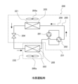
- FIG. 6 is a refrigerant circuit diagram during cooling operation of the air-conditioning apparatus 200 equipped with the heat exchanger 100 of the first embodiment.
- the heat exchanger 100 constitutes a part of a refrigerant circuit 250 through which the refrigerant circulates in the air-conditioning apparatus 200.
- the heat exchanger 100 is applied to either one or both of an outdoor heat exchanger 203 and an indoor heat exchanger 205, which will be described later.
- Air-conditioning device 200 has a compressor 201, a flow path switching device 202 that switches the flow path of the refrigerant, and an outdoor heat exchanger 203 that exchanges heat between the outdoor air and the refrigerant flowing inside. Air-conditioning device 200 also has an expansion valve 204 that reduces the pressure of the refrigerant flowing inside, and an indoor heat exchanger 205 that exchanges heat between the indoor air and the refrigerant flowing inside. Note that air-conditioning device 200 does not necessarily have to have a flow path switching device 202.
- the air conditioning device 200 includes a compressor 201, a flow path switching device 202, an outdoor heat exchanger 203, and an expansion valve 204 provided in an outdoor unit 231, and an indoor heat exchanger 205 provided in an indoor unit 232.
- the header section 50 (see FIG. 2), which serves as the refrigerant inlet and outlet of the heat exchanger 100, is connected to the flow path switching device 202 and the expansion valve 204 of the refrigerant circuit 250.
- a compressor 201 In the air conditioning device 200, a compressor 201, a flow path switching device 202, an outdoor heat exchanger 203, an expansion valve 204, and an indoor heat exchanger 205 are connected by refrigerant piping 255 to form a refrigerant circuit 250 in which the refrigerant circulates.
- the air conditioning device 200 shown in FIG. 6 can operate in both cooling and heating mode by switching the flow path switching device 202.
- the compressor 201 draws in low-temperature, low-pressure refrigerant, compresses it, and discharges high-temperature, high-pressure refrigerant.
- the flow path switching device 202 is, for example, a four-way valve, and switches between cooling and heating operations by switching the direction in which the refrigerant flows.
- the flow path switching device 202 connects the discharge side of the compressor 201 to the indoor heat exchanger 205 during heating operation, and connects the discharge side of the compressor 201 to the outdoor heat exchanger 203 during cooling operation.
- the outdoor heat exchanger 203 exchanges heat between the outdoor air and the refrigerant flowing inside the outdoor heat exchanger 203. As shown in FIG. 6, during cooling operation, the outdoor heat exchanger 203 functions as a condenser 221 that releases heat from the refrigerant to the outdoor air and condenses the refrigerant. During heating operation, the outdoor heat exchanger 203 also functions as an evaporator that evaporates the refrigerant and cools the outdoor air with the heat of vaporization.
- the expansion valve 204 is, for example, an electronic expansion valve that can adjust the throttle opening, and by adjusting the opening, the pressure of the refrigerant flowing into the outdoor heat exchanger 203 or the indoor heat exchanger 205 is controlled. Note that, in the embodiment, the expansion valve 204 is provided in the outdoor unit 231, but it may also be provided in the indoor unit 232, and the installation location is not limited.
- the indoor heat exchanger 205 exchanges heat between the indoor air and the refrigerant flowing inside the indoor heat exchanger 205. As shown in FIG. 6, during cooling operation, the indoor heat exchanger 205 functions as an evaporator 222 that evaporates the refrigerant and cools the outdoor air with the heat of vaporization. During heating operation, the indoor heat exchanger 205 functions as a condenser that releases heat from the refrigerant to the outdoor air to condense the refrigerant.
- the air conditioning device 200 may also have an outdoor fan 203a and an indoor fan 205a for blowing air to the outdoor heat exchanger 203 and the indoor heat exchanger 205.
- the outdoor fan 203a and the indoor fan 205a form a flow of air that flows through a flow path P2 (see FIG. 2) between adjacent heat transfer tubes 10.
- the air conditioning device 200 When the compressor 201 operates, the air conditioning device 200 performs a refrigeration cycle in which the refrigerant circulates through the compressor 201, the outdoor heat exchanger 203, the expansion valve 204, and the indoor heat exchanger 205 while undergoing a phase change.
- the refrigerant compressed by the compressor 201 is sent to the outdoor heat exchanger 203.
- the refrigerant releases heat to the outdoor air and is condensed.
- the refrigerant is then sent to the expansion valve 204, where it is decompressed, and then sent to the indoor heat exchanger 205.
- the refrigerant then absorbs heat from the indoor air in the indoor heat exchanger 205, evaporates, and then returns to the compressor 201. Therefore, when the air conditioner 200 is in cooling operation, the outdoor heat exchanger 203 functions as a condenser 221, and the indoor heat exchanger 205 functions as an evaporator 222.
- the refrigerant compressed by the compressor 201 is sent to the indoor heat exchanger 205.
- the refrigerant releases heat to the indoor air and is condensed.
- the refrigerant is then sent to the expansion valve 204, where it is decompressed, and then sent to the outdoor heat exchanger 203.
- the refrigerant then absorbs heat from the outdoor air in the outdoor heat exchanger 203 and evaporates, before returning to the compressor 201. Therefore, when the air conditioning device 200 is in heating operation, the outdoor heat exchanger 203 functions as an evaporator, and the indoor heat exchanger 205 functions as a condenser.
- the heat exchanger 100 includes a plurality of heat transfer tubes 10 arranged in a first direction D1, each extending in a second direction D2 intersecting the first direction D1, with both ends in the second direction D2 sealed and a refrigerant flowing through the inside.
- Each of the plurality of heat transfer tubes 10 has a plurality of through holes 30 formed inside the both ends and communicating the internal space of each of the plurality of heat transfer tubes 10 with the outside.
- the plurality of heat transfer tubes 10 have a plurality of connecting portions 12 that directly connect the plurality of through holes 30 of adjacent heat transfer tubes 10 among the plurality of heat transfer tubes 10.
- the multiple header sections 50 are provided in the central portions 17 of the multiple heat transfer tubes 10 in the second direction D2.
- the heat exchanger 100 can shorten the distance that the refrigerant flows out of the header sections 50 or flows into the header sections 50 rises inside the heat transfer tubes 10.
- the heat exchanger 100 can reduce the head difference and suppress liquid stagnation, compared to a case where the multiple header sections 50 are not provided at positions that divide the multiple heat transfer tubes 10 into upper and lower portions in the gravity direction.
- the heat exchanger 100 can gather the inlet and outlet of the refrigerant in the central portion, making it easier to handle the piping.
- each of the heat transfer tubes 10 has a partition portion 70 that is disposed in the internal space of the tube wall 11, extends in the second direction D2, and divides the internal space into a third direction D3 perpendicular to the first direction D1 and the second direction D2. Both ends of the partition portion 70 in the second direction D2 are located inside the ends of both sides of the heat transfer flow path P1a of the heat transfer tube 10 in the second direction D2.
- the multiple header portions 50 include a first header portion 51 that serves as a refrigerant inlet and a second header portion 52 that serves as a refrigerant outlet.
- the first header portion 51 and the second header portion 52 are provided on both sides of the partition portion 70 in the third direction D3, sandwiching the partition portion 70 therebetween.
- the heat exchanger 100 can easily branch the refrigerant flowing in from the first header portion 51 into upper and lower portions, and can increase the flow rate of the rising refrigerant by narrowing the flow path inside the heat transfer tube 10. Therefore, the heat exchanger 100 can easily raise the refrigerant compared to a case where the partition 70 is not included, thereby reducing the head difference and suppressing liquid stagnation.
- the air conditioning device 200 also includes a heat exchanger 100. Because the air conditioning device 200 includes the heat exchanger 100, it can achieve the effects of the heat exchanger 100 described above.
- the partition section 70 of the heat exchanger 100 according to the second embodiment is biased toward one side in the third direction D3.
- the partition section 70 is located closer to the first header section 51 than the central portion in the third direction D3.
- the heat exchanger 100 is formed so that the flow path cross-sectional area of the internal space on the first header section 51 side is smaller than the flow path cross-sectional area of the internal space on the second header section 52 side. That is, the heat exchanger 100 is formed so that the flow path cross-sectional area of the first flow path P1a1 is smaller than the flow path cross-sectional area of the second flow path P1a2.
- the heat exchanger 100 is a header section 50 in which a refrigerant with a higher liquid component than gas component flows in the first header section 51 than in the second header section 52.
- a refrigerant with a higher liquid component than gas component flows in the internal space on the second header section 52 side.
- a refrigerant with a higher liquid component than gas component flows in the second flow path P1a2.
- a refrigerant with a higher ratio of liquid component to gas component flows in the internal space on the first header section 51 side than in the internal space on the second header section 52 side.
- the first header section 51 is, for example, the header section 50 on the side where the refrigerant flows in when the heat exchanger 100 is an evaporator, and is the header section 50 on the side where the refrigerant flows out when the heat exchanger 100 is an evaporator.
- the heat exchanger 100 according to the second embodiment is applied to the indoor heat exchanger 205.
- the partition portion 70 in the heat exchanger 100 of the second embodiment is provided at a position closer to the first header portion 51 than to the central portion in the third direction D3. Therefore, the heat transfer tubes 10 of the heat exchanger 100 are formed so that the flow path cross-sectional area of the internal space on the first header portion 51 side is smaller than the flow path cross-sectional area of the internal space on the second header portion 52 side.
- a refrigerant with a larger liquid component than a gas component flows in the internal space on the first header portion 51 side than in the internal space on the second header portion 52 side.
- the heat exchanger 100 has the above configuration, which increases the flow rate of the refrigerant on the side with a larger liquid component compared to the side with a larger gas component, making it easier to raise the refrigerant compared to a case where the above configuration is not present, and further reduces the head difference and suppresses liquid stagnation.
- the heat exchanger 100 has the above configuration, which increases the flow rate of the refrigerant on the side with a larger liquid component, where heat transfer is more easily performed, compared to the refrigerant on the side with a larger gas component, improving the heat transfer coefficient and improving heat exchanger performance.
- the air conditioning device 200 also includes a heat exchanger 100. Because the air conditioning device 200 includes the heat exchanger 100, it can achieve the effects of the heat exchanger 100 described above.
- Embodiment 3. 9 is a perspective view showing a part of the inner surface of the heat transfer tube 10 of the heat exchanger 100 according to the embodiment 3.
- the heat exchanger 100 of the embodiment 3 is obtained by modifying the configuration of the heat transfer tube 10 in the heat exchanger 100 of the embodiment 1. Note that components having the same functions and actions as those of the embodiments 1 and 2 are denoted by the same reference numerals and the description thereof will be omitted.
- Each of the multiple heat transfer tubes 10 has at least one or more protrusions 60 that protrude into the internal space of the heat transfer tube 10.
- the protrusions 60 are formed in a protruding shape. There may be one or more protrusions 60.
- the heat exchanger 100 can narrow the heat transfer flow path P1a inside the heat transfer tube 10 by the protrusions 60. The refrigerant flows faster through a narrowed space than through an unnarrowed space.
- the convex portion 60 is preferably provided at a position closer to the through hole 30 than both ends of the heat transfer tube 10 in the second direction D2.
- the convex portion 60 is preferably provided at a position closer to the header portion 50 than both ends of the heat transfer tube 10 in the second direction D2.
- the protrusions 60 are preferably provided above the through-holes 30 or the header section 50. By providing the protrusions 60 above the through-holes 30 or the header section 50, the protrusions 60 can impart momentum to the refrigerant flowing upward.
- Each of the heat transfer tubes 10 in the heat exchanger 100 has at least one or more convex portions 60 protruding into the internal space of the heat transfer tube 10.
- the heat exchanger 100 can increase the flow rate of the refrigerant in the heat transfer tube 10 compared to a case where the convex portions 60 are not provided, so that the refrigerant can be easily raised, the head difference can be alleviated, and liquid stagnation can be suppressed.
- the heat exchanger 100 can also control the drift of the liquid refrigerant depending on the position of the convex portions 60, and can also adjust the refrigerant distribution in the heat transfer tube 10 while suppressing liquid stagnation, thereby improving the heat exchanger performance.
- the air conditioning device 200 also includes a heat exchanger 100. Because the air conditioning device 200 includes the heat exchanger 100, it can achieve the effects of the heat exchanger 100 described above.
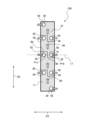
- Fig. 10 is a conceptual diagram of the heat exchanger 100 according to the fourth embodiment, viewed in the first direction D1.
- Fig. 11 is a conceptual diagram of a modified example of the heat exchanger 100 according to the fourth embodiment, viewed in the first direction D1.
- the heat exchanger 100 according to the fourth embodiment is obtained by modifying the configuration of the heat transfer tube 10 in the heat exchanger 100 according to the first embodiment. Note that in Fig. 10, the upper and lower partitions 90 provided inside the heat transfer tube 10 are indicated by dashed lines.
- the components having the same functions and actions as those in the first to third embodiments are denoted by the same reference numerals, and the description thereof will be omitted.
- each of the multiple heat transfer tubes 10 is disposed in the internal space of the tube wall 11 and has at least one upper and lower partitions 90 that extend through the internal space in a third direction D3 that is perpendicular to the first direction D1 and the second direction D2, respectively.
- the upper and lower partitions 90 separate two of the multiple header sections 50 arranged in parallel in the second direction D2, dividing the internal space of the heat transfer tube 10 into upper and lower sections.
- the upper and lower partitions 90 separate two of the multiple end header sections 55 arranged in parallel in the second direction D2, dividing the internal space of the heat transfer tube 10 into upper and lower sections.
- the heat exchanger 100 has two or more refrigerant paths formed by upper and lower partitions 90, multiple header sections 50, and end header sections 55.
- Figure 10 shows a heat exchanger 100 with two refrigerant paths as an example.
- Figure 11 shows a heat exchanger 100 with four refrigerant paths as an example.
- each of the multiple heat transfer tubes 10 is disposed in the internal space of the tube wall 11 and has an upper and lower partition 90 that separates the first header portion 51 and the second header portion 52.
- the upper and lower partitions 90 extend through the internal space of the heat transfer tube 10 in a third direction D3 that is perpendicular to the first direction D1 and the second direction D2, respectively, and divide the internal space of the heat transfer tube 10 into an upper space and a lower space.
- the internal space of the heat transfer tube 10 is separated by the upper and lower partitions 90 into an upper space 10f and a lower space 10g.
- the upper and lower partitions 90 are plate- or rod-shaped members that extend in the third direction D3 in the internal space of the heat transfer tube 10.
- the upper and lower partitions 90 shown in FIG. 10 are formed in a roughly Z-shape when viewed in the first direction D1, but are not limited to this shape.
- the upper and lower partitions 90 may be formed in an inclined straight line when viewed in the first direction D1 so that the height positions of both ends in the third direction D3 are different.
- the upper and lower partitions 90 are provided to connect with the tube side wall portions 10a and 10b (see FIG. 4).
- the upper and lower partitions 90 are provided to extend between the tube side wall portions 10a and 10b.
- the multiple header sections 50 include a first header section 51 that serves as the refrigerant inlet and a second header section 52 that serves as the refrigerant outlet.
- the multiple connection sections 12 or the multiple header tubes 80 form multiple end side header sections 55 formed to extend in the first direction D1.
- the end side header sections 55 communicate the refrigerant with the internal spaces of each of the multiple heat transfer tubes 10, and serve as the inlets and outlets for the refrigerant of the heat transfer tube group 15 formed by the multiple heat transfer tubes 10.
- the multiple end side header sections 55 are formed closer to the ends of the multiple heat transfer tubes 10 than the multiple header sections 50 in the second direction D2.
- the end side header section 55 is configured with the same structure as the header section 50. That is, the end side header section 55 is configured by directly or indirectly connecting the through holes 30 of the heat transfer tubes 10. The end side header section 55 is configured with the connecting section 12 or the header tube 80. The end side header section 55 is provided closer to the end of the heat transfer tube 10 than the header section 50 provided in the center section 17.
- the multiple end side header sections 55 include a third header section 56 which serves as the refrigerant inlet and a fourth header section 57 which serves as the refrigerant outlet.
- the third header section 56 is formed below the first header section 51 and the second header section 52, and forms a refrigerant inlet through which the refrigerant flowing out from the second header section 52 flows.
- the fourth header section 57 is formed above the first header section 51 and the second header section 52, and forms a refrigerant outlet through which the refrigerant flowing in from the first header section 51 flows out.
- a header flow path P1e or a header flow path P1f is formed inside the header pipe 80 or the connecting portion 12.
- the header pipe 80 or the connecting portion 12 that constitutes the third header portion 56 constitutes the header flow path P1e
- the header pipe 80 or the connecting portion 12 that constitutes the fourth header portion 57 constitutes the header flow path P1f.
- the refrigerant flow path of the heat exchanger 100 of the fourth embodiment is composed of a plurality of heat transfer flow paths P1a and header flow paths P1b and P1c (see FIG. 3) that are arranged in parallel in the front and rear of the central portion 17 of the heat exchanger 100.
- the refrigerant flow path of the heat exchanger 100 is composed of header flow paths P1e and P1f that are arranged closer to the end side in the second direction D2 than the central portion 17 of the heat exchanger 100.
- the heat transfer flow path P1a communicates with the header flow path P1e and the header flow path P1f at the end side of the heat transfer flow path P1a in the longitudinal direction (second direction D2) of the heat transfer tube 10.
- the header flow path P1e and the header flow path P1f each communicate with a plurality of heat transfer flow paths P1a.
- the connecting portion 12 see FIG. 2
- the above-mentioned through hole 30a, the through hole 30b, and the hollow portion Sg of the connecting portion 12 constitute the header flow path P1e and the header flow path P1f, and the refrigerant flows through the hollow portion Sg.
- the heat exchanger 100 has a header flow path P1b, a header flow path P1c, a header flow path P1e, and a header flow path P1f formed in the heat transfer tubes 10, which are heat exchange members, so there is no need to provide a header section on the outside of the multiple heat transfer tubes 10.
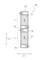
- FIG. 12 is a conceptual diagram of a heat exchanger 100L according to a comparative example viewed in the first direction D1.
- the heat exchanger 100L according to the comparative example is a conventional heat exchanger having header portions 50L at both ends of the heat transfer tube 10L in the second direction D2. Since the heat exchanger 100 according to the comparative example has the header portions 50L at both ends of the heat transfer tube 10L in the second direction D2, the effective area E for heat exchange by the heat transfer tube 10L is reduced compared to when the heat exchanger 100 does not have the header portions 50.
- the multiple connection parts 12 or multiple header tubes 80 in the heat exchanger 100 according to the fourth embodiment constitute multiple end-side header sections 55 formed to extend in the first direction D1.
- the end-side header section 55 communicates the refrigerant with the internal space of each of the multiple heat transfer tubes 10, and serves as an inlet and outlet for the refrigerant of the heat transfer tube group 15 formed by the multiple heat transfer tubes 10.
- the multiple end-side header sections 55 are configured closer to the end of the multiple heat transfer tubes 10 than the multiple header sections 50 in the second direction D2.
- Each of the multiple heat transfer tubes 10 is disposed in the internal space of the tube wall 11, extends through the internal space in a third direction D3 perpendicular to the first direction D1 and the second direction D2, and has at least one or more upper and lower partition sections 90 that divide the internal space of the heat transfer tube 10 into upper and lower sections.
- the upper and lower partition sections 90 separate two of the multiple header sections 50 that are arranged in parallel in the second direction D2.
- the upper and lower partitions 90 separate two end header sections 55 that are arranged in parallel in the second direction D2 among the multiple end header sections 55.
- the upper and lower partitions 90, the multiple header sections 50, and the end header sections 55 form two or more refrigerant paths.
- the heat exchanger 100 according to the fourth embodiment has a header section provided directly on the heat transfer tube 10 by a plurality of header sections 50 and a plurality of end side header sections 55. Therefore, in the heat exchanger 100 according to the fourth embodiment, the effective area E for heat exchange is not reduced by the header section as in the comparative heat exchanger 100L shown in FIG. 12.
- the effective area E for heat exchange in the heat exchanger 100 is larger than the effective area E for heat exchange in the heat exchanger 100L of the comparative example shown in FIG. 12. That is, in the conventional heat exchanger 100L such as the comparative example, the effective area for heat exchange, which was reduced when the header section 50L was disposed above and below the heat transfer tube 10L, is increased in the heat exchanger 100 according to the fourth embodiment. Therefore, the heat exchanger 100 according to the fourth embodiment has a larger effective area for heat exchange and can improve the heat exchange efficiency compared to the heat exchanger 100L not having the above configuration.
- the heat exchanger 100 has at least one or more upper and lower partitions 90 that divide the internal space of the heat transfer tube 10 into upper and lower spaces.
- the heat exchanger 100 shortens the distance that the refrigerant rises compared to a case in which the heat exchanger 100 does not have the upper and lower partitions 90. Therefore, the heat exchanger 100 can reduce the head difference and suppress liquid stagnation compared to a case in which the heat exchanger 100 does not have the upper and lower partitions 90, thereby improving the heat exchange efficiency.
- the upper and lower partitions 90 are disposed in the internal space of the pipe wall 11 and separate the first header section 51 and the second header section 52.
- the third header section 56 is formed below the first header section 51 and the second header section 52, and forms a refrigerant inlet through which the refrigerant flowing out from the second header section 52 flows.
- the fourth header section 57 is formed above the first header section 51 and the second header section 52, and forms a refrigerant outlet through which the refrigerant flowing in from the first header section 51 flows out.
- the heat exchanger 100 does not have a reduced effective area E for heat exchange due to the header section as in the comparative heat exchanger 100L shown in FIG. 12. Therefore, the heat exchanger 100 according to the fourth embodiment has a wider effective area for heat exchange and can improve heat exchange efficiency compared to the heat exchanger 100L not having this configuration.
- the air conditioning device 200 also includes a heat exchanger 100. Because the air conditioning device 200 includes the heat exchanger 100, it can achieve the effects of the heat exchanger 100 described above.
- Embodiment 5 is a conceptual diagram of the heat exchanger 100 according to the fifth embodiment, viewed in a first direction D1. Note that components having the same functions and actions as those in the first to fourth embodiments are given the same reference numerals and will not be described.
- the total flow path cross-sectional area A of the heat transfer tubes 10 can be calculated by the following formula (1).
- A a ⁇ N [m 2 ]...(1) a: flow passage cross-sectional area per one of the heat transfer tubes 10 [m 2 ] N: Number of heat transfer tubes 10 [pieces]
- ⁇ P HEX differential pressure in the refrigerant flow path
- ⁇ P HEAD liquid head
- ⁇ P HEX / ⁇ P HEAD can be calculated by the following formula (2).
- the flow path differential pressure ⁇ P HEX is the differential pressure in the flow path through which the refrigerant flows as an ascending flow, and is the differential pressure between the upper and lower ends of the heat transfer tubes 10 in the heat transfer tube group 15.
- ⁇ P HEX / ⁇ P HEAD (5.94635 ⁇ 10-4 ⁇ A-1.75030)/(8.4303HSin ⁇ +0.8779)>1...(2)
- H Length of the heat transfer tube 10 in the second direction D2 [m]
- ⁇ the inclination angle [°] of the plurality of heat transfer tubes 10 with respect to the horizontal plane F when the first direction D1 is parallel to the horizontal plane F
- the length H [m] of the heat transfer tube 10 in the second direction D2 is particularly effective when it is longer than 0.420 [m] (length H > 0.420).
- Many heat exchangers using corrugated fins used in outdoor unit units such as car air conditioners have heat transfer tubes that are approximately 0.300 [m] long, whereas many heat exchangers used in outdoor unit units for buildings, etc. have heat transfer tubes that are 0.420 [m] long or longer.
- the inventors According to the research of the inventors, it was found that, for example, when the length H of the heat transfer tube 10 is increased to about 0.420 [m], ⁇ P HEX / ⁇ P HEAD is lower than that of a tube with a length of 0.300 [m].
- the inventors also found that when the length H of the heat transfer tube in the heat exchanger is 0.420 [m] or more, a head difference occurs, and liquid retention occurs in which the liquid refrigerant does not easily flow in a part of the heat exchanger.
- the heat exchanger 100 according to the fifth embodiment can suppress liquid retention by satisfying the above formula (2) even when the length H [m] of the heat transfer tube in the second direction D2 is longer than 0.420 [m], and can improve the heat exchanger performance.
- the above formula (2) is an empirical formula obtained by the inventors' numerical analysis and experimental results.
- Formula (2) is formulated using the total flow path cross-sectional area A [m 2 ] of the heat transfer tubes 10, which is a shape parameter of the heat exchanger 100 in which the flow path differential pressure ⁇ P HEX is dominant, and the length H [m] of the heat transfer tube 10, which is a shape parameter of the heat exchanger 100 in which the liquid head ⁇ P HEAD is dominant.
- Formula (2) is formulated within a range of conditions in which the heat exchanger 100 is used in an outdoor unit 231 (see FIG. 6 ) for buildings, stores, homes, etc.
- ⁇ P HEX / ⁇ P HEAD (5.94635 ⁇ 10-4 ⁇ A - 1.75030) / (8.4303HSin ⁇ + 0.8779) > 1.
- the air conditioning device 200 also includes a heat exchanger 100. Because the air conditioning device 200 includes the heat exchanger 100, it can achieve the effects of the heat exchanger 100 described above.
- the present disclosure is not limited to the above-described embodiments.
- the present disclosure may be configured by combining the various embodiments.
Landscapes
- Engineering & Computer Science (AREA)
- Physics & Mathematics (AREA)
- Mechanical Engineering (AREA)
- Thermal Sciences (AREA)
- General Engineering & Computer Science (AREA)
- Geometry (AREA)
- Heat-Exchange Devices With Radiators And Conduit Assemblies (AREA)
- Air Filters, Heat-Exchange Apparatuses, And Housings Of Air-Conditioning Units (AREA)
- Other Air-Conditioning Systems (AREA)
Priority Applications (4)
| Application Number | Priority Date | Filing Date | Title |
|---|---|---|---|
| EP23935293.3A EP4703668A1 (en) | 2023-04-26 | 2023-04-26 | Heat exchanger and air conditioning device |
| CN202380097160.XA CN121039455A (zh) | 2023-04-26 | 2023-04-26 | 热交换器以及空气调节装置 |
| PCT/JP2023/016467 WO2024224513A1 (ja) | 2023-04-26 | 2023-04-26 | 熱交換器及び空気調和装置 |
| JP2023573129A JP7459402B1 (ja) | 2023-04-26 | 2023-04-26 | 熱交換器及び空気調和装置 |
Applications Claiming Priority (1)
| Application Number | Priority Date | Filing Date | Title |
|---|---|---|---|
| PCT/JP2023/016467 WO2024224513A1 (ja) | 2023-04-26 | 2023-04-26 | 熱交換器及び空気調和装置 |
Publications (1)
| Publication Number | Publication Date |
|---|---|
| WO2024224513A1 true WO2024224513A1 (ja) | 2024-10-31 |
Family
ID=90474225
Family Applications (1)
| Application Number | Title | Priority Date | Filing Date |
|---|---|---|---|
| PCT/JP2023/016467 Ceased WO2024224513A1 (ja) | 2023-04-26 | 2023-04-26 | 熱交換器及び空気調和装置 |
Country Status (4)
| Country | Link |
|---|---|
| EP (1) | EP4703668A1 (https=) |
| JP (1) | JP7459402B1 (https=) |
| CN (1) | CN121039455A (https=) |
| WO (1) | WO2024224513A1 (https=) |
Citations (6)
| Publication number | Priority date | Publication date | Assignee | Title |
|---|---|---|---|---|
| JPS6321495A (ja) * | 1986-07-14 | 1988-01-29 | Nippon Denso Co Ltd | 積層型熱交換器 |
| JPH0460392A (ja) * | 1990-06-29 | 1992-02-26 | Hitachi Ltd | 積層形熱交換器 |
| US5099913A (en) * | 1990-02-05 | 1992-03-31 | General Motors Corporation | Tubular plate pass for heat exchanger with high volume gas expansion side |
| JPH0718172U (ja) * | 1993-08-19 | 1995-03-31 | 株式会社ゼクセル | 積層型熱交換器 |
| JP2017072331A (ja) * | 2015-10-09 | 2017-04-13 | 有限会社和氣製作所 | 熱交換器およびその製造方法 |
| JP2022070491A (ja) * | 2020-10-27 | 2022-05-13 | 有限会社和氣製作所 | 熱交換器 |
Family Cites Families (2)
| Publication number | Priority date | Publication date | Assignee | Title |
|---|---|---|---|---|
| ITMC20070143A1 (it) * | 2007-07-11 | 2009-01-12 | Brandoni Srl | Radiatore per riscaldamento. |
| KR102817989B1 (ko) * | 2020-04-03 | 2025-06-09 | 한온시스템 주식회사 | 플레이트 적층형 열교환기 |
-
2023
- 2023-04-26 CN CN202380097160.XA patent/CN121039455A/zh active Pending
- 2023-04-26 WO PCT/JP2023/016467 patent/WO2024224513A1/ja not_active Ceased
- 2023-04-26 JP JP2023573129A patent/JP7459402B1/ja active Active
- 2023-04-26 EP EP23935293.3A patent/EP4703668A1/en active Pending
Patent Citations (6)
| Publication number | Priority date | Publication date | Assignee | Title |
|---|---|---|---|---|
| JPS6321495A (ja) * | 1986-07-14 | 1988-01-29 | Nippon Denso Co Ltd | 積層型熱交換器 |
| US5099913A (en) * | 1990-02-05 | 1992-03-31 | General Motors Corporation | Tubular plate pass for heat exchanger with high volume gas expansion side |
| JPH0460392A (ja) * | 1990-06-29 | 1992-02-26 | Hitachi Ltd | 積層形熱交換器 |
| JPH0718172U (ja) * | 1993-08-19 | 1995-03-31 | 株式会社ゼクセル | 積層型熱交換器 |
| JP2017072331A (ja) * | 2015-10-09 | 2017-04-13 | 有限会社和氣製作所 | 熱交換器およびその製造方法 |
| JP2022070491A (ja) * | 2020-10-27 | 2022-05-13 | 有限会社和氣製作所 | 熱交換器 |
Also Published As
| Publication number | Publication date |
|---|---|
| EP4703668A1 (en) | 2026-03-04 |
| JP7459402B1 (ja) | 2024-04-01 |
| CN121039455A (zh) | 2025-11-28 |
| JPWO2024224513A1 (https=) | 2024-10-31 |
Similar Documents
| Publication | Publication Date | Title |
|---|---|---|
| US9651317B2 (en) | Heat exchanger and air conditioner | |
| US10041710B2 (en) | Heat exchanger and air conditioner | |
| EP3290851B1 (en) | Layered header, heat exchanger, and air conditioner | |
| US20160169586A1 (en) | Heat exchanger, air-conditioning apparatus, refrigeration cycle apparatus and method for manufacturing heat exchanger | |
| US11555655B2 (en) | Heat exchanger and heat pump device | |
| KR102174510B1 (ko) | 냉장고의 냉각 사이클 | |
| AU2012208118A1 (en) | Heat exchanger and air conditioner | |
| US11280551B2 (en) | Micro channel type heat exchanger | |
| EP3473963A1 (en) | Heat exchanger and air conditioner | |
| JP6890509B2 (ja) | 空気調和機 | |
| EP3789697B1 (en) | Heat exchanger and refrigeration cycle device | |
| JP6104378B2 (ja) | 空気調和装置 | |
| JPH09318195A (ja) | 積層型蒸発器 | |
| WO2024224513A1 (ja) | 熱交換器及び空気調和装置 | |
| JP2020148346A (ja) | 熱交換器及び空気調和機 | |
| JP7146139B1 (ja) | 熱交換器及び空気調和装置 | |
| JPWO2016121124A1 (ja) | 熱交換器、及び冷凍サイクル装置 | |
| WO2024189823A1 (ja) | 熱交換器およびそれを備えた空気調和装置 | |
| US20080066487A1 (en) | Condenser and radiator of air conditioning refrigeration system | |
| EP3971507A1 (en) | Heat exchanger and refrigeration cycle device | |
| JP7455290B1 (ja) | 熱交換器及び空気調和装置 | |
| JP7642170B1 (ja) | 熱交換器、熱交換器を備えた室外機、および、室外機を備えた空気調和装置 | |
| JP7724953B2 (ja) | 熱交換器及びこれを有する空気調和装置 | |
| CN216347190U (zh) | 过冷器、电控盒以及空调系统 | |
| WO2020230268A1 (ja) | 熱交換器及び冷凍サイクル装置 |
Legal Events
| Date | Code | Title | Description |
|---|---|---|---|
| WWE | Wipo information: entry into national phase |
Ref document number: 2023573129 Country of ref document: JP |
|
| 121 | Ep: the epo has been informed by wipo that ep was designated in this application |
Ref document number: 23935293 Country of ref document: EP Kind code of ref document: A1 |
|
| WWE | Wipo information: entry into national phase |
Ref document number: CN202380097160X Country of ref document: CN |
|
| WWE | Wipo information: entry into national phase |
Ref document number: 2023935293 Country of ref document: EP |
|
| NENP | Non-entry into the national phase |
Ref country code: DE |
|
| ENP | Entry into the national phase |
Ref document number: 2023935293 Country of ref document: EP Effective date: 20251126 |
|
| ENP | Entry into the national phase |
Ref document number: 2023935293 Country of ref document: EP Effective date: 20251126 |
|
| ENP | Entry into the national phase |
Ref document number: 2023935293 Country of ref document: EP Effective date: 20251126 |
|
| ENP | Entry into the national phase |
Ref document number: 2023935293 Country of ref document: EP Effective date: 20251126 |
|
| ENP | Entry into the national phase |
Ref document number: 2023935293 Country of ref document: EP Effective date: 20251126 |
|
| ENP | Entry into the national phase |
Ref document number: 2023935293 Country of ref document: EP Effective date: 20251126 |
|
| ENP | Entry into the national phase |
Ref document number: 2023935293 Country of ref document: EP Effective date: 20251126 |
|
| ENP | Entry into the national phase |
Ref document number: 2023935293 Country of ref document: EP Effective date: 20251126 |
|
| ENP | Entry into the national phase |
Ref document number: 2023935293 Country of ref document: EP Effective date: 20251126 |
|
| WWP | Wipo information: published in national office |
Ref document number: 2023935293 Country of ref document: EP |