WO2024224507A1 - 制御装置及びリソース割当方法 - Google Patents
制御装置及びリソース割当方法 Download PDFInfo
- Publication number
- WO2024224507A1 WO2024224507A1 PCT/JP2023/016443 JP2023016443W WO2024224507A1 WO 2024224507 A1 WO2024224507 A1 WO 2024224507A1 JP 2023016443 W JP2023016443 W JP 2023016443W WO 2024224507 A1 WO2024224507 A1 WO 2024224507A1
- Authority
- WO
- WIPO (PCT)
- Prior art keywords
- switch
- server
- processing load
- unit
- information
- Prior art date
- Legal status (The legal status is an assumption and is not a legal conclusion. Google has not performed a legal analysis and makes no representation as to the accuracy of the status listed.)
- Ceased
Links
Images




Classifications
-
- H—ELECTRICITY
- H04—ELECTRIC COMMUNICATION TECHNIQUE
- H04L—TRANSMISSION OF DIGITAL INFORMATION, e.g. TELEGRAPHIC COMMUNICATION
- H04L41/00—Arrangements for maintenance, administration or management of data switching networks, e.g. of packet switching networks
- H04L41/40—Arrangements for maintenance, administration or management of data switching networks, e.g. of packet switching networks using virtualisation of network functions or resources, e.g. SDN or NFV entities
-
- H—ELECTRICITY
- H04—ELECTRIC COMMUNICATION TECHNIQUE
- H04L—TRANSMISSION OF DIGITAL INFORMATION, e.g. TELEGRAPHIC COMMUNICATION
- H04L47/00—Traffic control in data switching networks
- H04L47/70—Admission control; Resource allocation
- H04L47/76—Admission control; Resource allocation using dynamic resource allocation, e.g. in-call renegotiation requested by the user or requested by the network in response to changing network conditions
Definitions
- the present invention relates to a control device and a resource allocation method.
- Non-Patent Document 1 claims that, since the control plane (C-Plane) and data plane (D-Plane) require different amounts of processing, by separating the control plane and data plane (CUPS: Control and User Plane Separation), the number of servers for the C-plane and the servers for the D-plane can be increased almost independently.
- C-Plane control plane
- D-Plane data plane
- CUPS Control and User Plane Separation
- Non-patent document 2 describes multi-access edge computing (MEC), which processes data at the facilities of a telecommunications carrier.
- MEC multi-access edge computing
- edge computing ensures low latency by performing processing that requires low latency, which would not be met if data were transferred from the terminal device to a data center far away before processing, on a computer located at the telecommunications carrier's base.
- the present invention aims to provide technology that can efficiently utilize computing resources.
- One aspect of the present invention is a control device that allocates computing resources to virtualized network functions and applications, the control device including an acquisition unit that acquires information that affects the processing load of the computing resources, an allocation determination unit that determines the amount of computing resources to be allocated to each of the network functions and the applications based on the information that affects the processing load of the computing resources acquired by the acquisition unit, and a communication unit that transmits information on the amount of computing resources determined by the allocation determination unit to one or more computers to which the resources are to be allocated.
- One aspect of the present invention is a resource allocation method performed by a control device that allocates computing resources to virtualized network functions and applications, which acquires information that affects the processing load of the computing resources, determines the amount of computing resources to be allocated to each of the network functions and the applications based on the acquired information that affects the processing load of the computing resources, and transmits information on the determined amount of computing resources to one or more computers to which the resources are to be allocated.
- the present invention makes it possible to use computing resources efficiently.
- FIG. 1 is a diagram illustrating an example of the configuration of a communication system according to an embodiment.
- FIG. 4 is a diagram illustrating an example of a profile table in the embodiment. 4 is a flowchart showing a process flow of a controller in the embodiment.
- FIG. 1 is a diagram illustrating an example of the configuration of a communication system according to an embodiment. 4 is a flowchart showing a process flow of a controller in the embodiment.
- FIG. 1 is a diagram showing a configuration in which a communication system in an embodiment is applied to a mobile system.
- FIG. 1 is a diagram showing a configuration (part 1) in which some devices of a communication system according to an embodiment are accommodated in a rack.
- FIG. 13 is a diagram showing a configuration (part 2) in which some devices of a communication system in an embodiment are accommodated in a rack.
- FIG. 1 is a diagram showing a configuration in which a communication system in an embodiment is applied to a PON system.
- FIG. 13 is a diagram illustrating an example of another profile table.
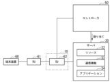
- Fig. 1 is a diagram showing an example of the configuration of a communication system 100 according to an embodiment.
- the communication system 100 includes a base station 10, one or more servers 30, and a controller 50.
- one server 30 is shown as one or more servers 30. Note that the number of base stations 10 and servers 30 is not particularly limited.
- the base station 10 and the server 30, the base station 10 and the controller 50, and the server 30 and the controller 50 are connected by wires.
- One or more terminal devices are connected wirelessly to the base station 10.
- the upper NW 40 is located above the server 30.
- the base station 10 performs wireless communication with one or more terminal devices.
- the base station 10 is, for example, a gNB in 5G or a DU (Distributed Unit) or CU (Central Unit) when functional division is performed.
- the base station 10 includes a wireless scheduler 11 and a main signal processing unit 12.
- the wireless scheduler 11 acquires information that affects the processing load of the computational resources in communication with the terminal devices.
- Information that affects the processing load of the computational resources is information about the data transmitted by the terminal devices, such as information about the amount of traffic and the number of terminal devices 60 connected to the server 30 (hereinafter referred to as the "number of connected terminal devices").
- the number of terminal devices the number of terminal devices 60 connected to the server 30.
- the wireless scheduler 11 notifies the controller 50 of the acquired amount of traffic.
- the main signal processing unit 12 processes the main signal transmitted from the terminal device. Specifically, the main signal processing unit 12 transfers the main signal transmitted from the terminal device to the destination server 30.
- the server 30 processes the main signal sent from the terminal device according to the resources allocated by the controller 50.
- the server 30 includes a processing load profile measurement unit 31, resources 32, a communication function 33, and an application 34.
- the processing load profile measurement unit 31 measures the processing load according to the input traffic volume for each function used by the server 30.
- the functions used by the server 30 are, for example, the communication function 33 and the application 34.
- the processing load profile measurement unit 31 measures the processing load for each input traffic volume for each of the communication function 33 and the application 34.
- the processing load profile measurement unit 31 creates a profile table that summarizes the measurement results.
- the processing load profile measurement unit 31 transmits the generated profile table to the controller 50. The values registered in the profile table differ for each server 30.
- the processing load profile measuring unit 31 may measure the processing load during operation, may measure the processing load when the server 30 is installed so as not to affect services during operation, or may measure the processing load in advance before installation and store only the results in the controller 50. Note that if the processing load is measured in advance before the server 30 is installed, the processing load profile measuring unit 31 does not need to be provided in the server 30 during actual operation.
- FIG. 2 is a diagram showing an example of a profile table in an embodiment.
- FIG. 2A shows the measurement results of the processing load for each traffic amount in the communication function 33
- FIG. 2B shows the measurement results of the processing load for each traffic amount in the application 34.
- FIG. 2 shows the measurement results when the server 30 can use 3 cores as resources.
- the measurement results registered in the profile table will be explained.
- the traffic amount input to the communication function 33 is 10 kB (kilo Byte) per ms, it is shown that when 1 core is used as a resource, the processing load is 10%, when 2 cores are used, the processing load is 10%, and when 3 cores are used, the processing load is 10%.
- the traffic amount input to the application 34 is 10 kB per ms, it is shown that when 1 core is used as a resource, the processing load is 20%, when 2 cores are used, the processing load is 20%, and when 3 cores are used, the processing load is 17%.
- the resource 32 is hardware (including circuitry) such as one or more processors such as a CPU or an FPGA (Field Programmable Gate Array).
- the resource 32 processes the main signal using a calculation resource according to an instruction from the controller 50.
- the communication function 33 is a communication device realized on a virtual machine by the virtualization technology of the resource 32.
- the communication function 33 performs a transfer process for transferring a main signal to a destination.
- the communication function 33 is, for example, a UPF (User Plane Function).
- Application 34 is software executed by resource 32.
- Application 34 is, for example, an image processing application.
- the processing load of both communication function 33 and application 34 varies depending on the amount of input traffic.
- the controller 50 controls each device included in the communication system 100.
- the controller 50 includes a communication unit 51, a storage unit 52, and a control unit 53.
- the controller 50 is one aspect of a control device.
- the communication unit 51 communicates with other devices.
- the communication unit 51 receives, for example, information on traffic volume from the base station 10.
- the communication unit 51 receives, for example, a profile table transmitted from each server 30.
- the communication unit 51 transmits, for example, resource allocation information to each server 30.
- the resource allocation information is information that indicates the amount of computational resources used in the server 30.
- the resource allocation information is information that indicates how many cores are used for which function.
- the storage unit 52 stores the profile tables 521 transmitted from each server 30. Therefore, if the communication system 100 includes multiple servers 30, multiple profile tables 521 are stored in the storage unit 52.
- the storage unit 52 is configured using a storage device such as a magnetic storage device or a semiconductor storage device.
- the control unit 53 is configured using one or more processors such as a CPU and a memory.
- the control unit 53 executes a program to realize the functions of the acquisition unit 531 and the allocation determination unit 532.
- a part or all of the acquisition unit 531 and the allocation determination unit 532 may be realized by hardware (including circuitry) such as an ASIC (Application Specific Integrated Circuit), PLD (Programmable Logic Device), or FPGA, or may be realized by a combination of software and hardware.
- the program may be recorded on a computer-readable recording medium.
- a computer-readable recording medium is, for example, a non-transitory storage medium such as a portable medium such as a flexible disk, optical magnetic disk, ROM, or CD-ROM, or a storage device such as a hard disk built into a computer system.
- the program may be transmitted via a telecommunications line.
- Some of the functions of the acquisition unit 531 and the allocation determination unit 532 do not need to be pre-installed in the controller 50, and may be realized by installing additional application programs in the controller 50.
- the acquisition unit 531 acquires various information received by the communication unit 51.
- the acquisition unit 531 associates the received profile table with the identification information of the server 30 and stores it in the storage unit 52.
- the acquisition unit 531 acquires information on the traffic volume received by the communication unit 51.
- the acquisition unit 531 outputs the acquired traffic volume information to the allocation determination unit 532.
- the allocation determination unit 532 acquires information on the processing load of each of the communication functions 33 and applications 34 of the server 30 based on the traffic volume information output from the acquisition unit 531 and the profile table 521. The allocation determination unit 532 determines the amount of computational resources to be allocated to the communication functions 33 and applications 34 based on the acquired information on the processing load of each function.
- FIG. 3 is a flowchart showing the flow of processing by the controller 50 in this embodiment. Note that the description will be given assuming that the profile table 521 shown in FIG. 2 is stored in the storage unit 52 of the controller 50 at the time of the processing in FIG. 3.
- the communication unit 51 receives traffic volume information transmitted from the base station 10.
- the communication unit 51 outputs the received traffic volume information to the control unit 53.
- the acquisition unit 531 of the control unit 53 acquires the traffic volume information output from the communication unit 51 (step S101).
- the acquisition unit 531 outputs the acquired traffic volume information to the allocation determination unit 532.
- the allocation determination unit 532 acquires information on the processing load of each of the communication functions 33 and applications 34 of the server 30 based on the traffic volume information output from the acquisition unit 531 and the profile table 521 (step S102). Specifically, the allocation determination unit 532 first reads the profile table 521 stored in the control unit 53. Next, the allocation determination unit 532 refers to the read profile table 521 to acquire information on the processing load of each of the communication functions 33 and applications 34 of the server 30. For example, if the traffic volume is 40 KB per ms and 3 cores are available in the server 30, the allocation determination unit 532 acquires 12% as information on the processing load of the communication functions 33 and 19% as information on the processing load of the applications 34.
- the allocation determination unit 532 determines whether or not resources can be allocated to each function based on the acquired information on the processing load of each of the communication functions 33 and the application 34 (step S103). The allocation determination unit 532 determines that resources can be allocated to each function when the total sum of the processing load of the communication functions 33 and the processing load of the application 34 is below 100%. On the other hand, the allocation determination unit 532 determines that resources cannot be allocated to each function when the total sum of the processing load of the communication functions 33 and the processing load of the application 34 exceeds 100%.
- step S103-NO determines that resources cannot be allocated to each function
- step S103-YES determines that resources can be allocated to each function
- step S104 allocates computational resources to each function of the server 30.
- the processing load of the communication function 33 is 12% and the processing load of the application 34 is 19%, so the total processing load is less than 100%. Therefore, in the server 30, the application 34 can be processed at approximately the same time as the communication function 33 is processed. Therefore, the allocation determination unit 532 determines that processing is possible even if computational resources are allocated within the same server 30.
- the allocation determination unit 532 generates resource allocation information indicating that 3 cores are to be allocated as computational resources to each of the communication function 33 and the application 34.
- the allocation determination unit 532 transmits the generated resource allocation information to the server 30 via the communication unit 51.
- the server 30 allocates 3 cores as computational resources to the communication function 33 and the application 34 based on the resource allocation information transmitted from the controller 50.
- the communication system 100 is configured to include one server 30, so if the processing load exceeds the capacity of the server 30, it may not be possible to process the main signal transmitted from the terminal device. Therefore, the communication system 100 may be configured to include multiple servers 30 as shown in FIG. 4.
- FIG. 4 is a diagram showing an example of the configuration of a communication system 100a in an embodiment.
- the communication system 100a includes a base station 10, a switching device 20, a plurality of servers 30, and a controller 50.
- two servers 30-1 and 30-2 are shown as the plurality of servers 30. Note that the number of base stations 10 and servers 30 is not particularly limited.
- server 30 when there is no need to distinguish between the servers 30-1 and 30-2, they will be referred to as server 30.
- the base station 10 and the switching device 20, the switching device 20 and each server 30, the base station 10 and the controller 50, the switching device 20 and the controller 50, and the servers 30 and the controller 50 are connected by wires.
- One or more terminal devices (not shown) are connected wirelessly to the base station 10.
- the upper NW 40 is located above the server 30. In the following description, it is assumed that the base station 10 is connected to the server 30-1 via the switching device 20.
- Communication system 100a differs from communication system 100 in that a switching device 20 is provided between base station 10 and multiple servers 30, and that a controller 50 issues instructions to switch paths.
- a switching device 20 is provided between base station 10 and multiple servers 30, and that a controller 50 issues instructions to switch paths.
- the following explanation will focus on the differences.
- the switching device 20 switches the transfer path of the main signal transmitted from the base station 10 in response to an instruction from the controller 50.
- the switching device 20 may be, for example, an L2 switch or an optical switch.
- Servers 30-1 and 30-2 have the same configuration.
- the sub-numbers "-1" and “-2" are added to distinguish between the functional units of servers 30-1 and 30-2.
- the functional units of server 30-1 they will be described as processing load profile measurement unit 31-1, resource 32-1, communication function 33-1, and application 34-1.
- the resource 32 of server 30-2 has a larger capacity than the resource 32 of server 30-1.
- the controller 50 controls each device included in the communication system 100a.
- the controller 50 includes a communication unit 51, a memory unit 52, and a control unit 53.
- the communication unit 51 performs the same processing as the communication unit 51 shown in FIG. 1. Furthermore, the communication unit 51 transmits a switching instruction to the switching device 20.
- the switching instruction is an instruction for switching the connection destination of the base station 10.
- the information that can uniquely identify the server 30 is, for example, the MAC address of the server 30. Note that the information that can uniquely identify the server 30 is not limited to the MAC address of the server 30, and may be other information that can uniquely identify the server 30.
- the storage unit 52 stores the profile tables 521 sent from each server 30.
- the storage unit 52 shown in FIG. 4 stores at least a profile table in which the measurement results of the processing load of each function of server 30-1 are registered, and a profile table in which the measurement results of the processing load of each function of server 30-2 are registered.
- the storage unit 52 is configured using a storage device such as a magnetic storage device or a semiconductor storage device.
- the control unit 53 is configured using one or more processors such as a CPU and a memory.
- the control unit 53 executes a program to realize the functions of the acquisition unit 531, the allocation determination unit 532, and the switching instruction unit 533.
- acquisition unit 531, allocation determination unit 532, and switching instruction unit 533 may be realized by hardware (including circuitry) such as an ASIC, PLD, or FPGA, or by a combination of software and hardware.
- the program may be recorded on a computer-readable recording medium.
- a computer-readable recording medium is, for example, a non-transitory storage medium such as a portable medium such as a flexible disk, optical magnetic disk, ROM, or CD-ROM, or a storage device such as a hard disk built into a computer system.
- the program may be transmitted via a telecommunications line.
- Some of the functions of the acquisition unit 531, the allocation determination unit 532, and the switching instruction unit 533 do not need to be pre-installed in the controller 50, and may be realized by installing additional application programs in the controller 50.
- the allocation determination unit 532 acquires information on the processing load of each of the communication functions 33 and applications 34 of the server 30 based on the traffic volume information output from the acquisition unit 531 and the profile table 521. The allocation determination unit 532 determines the amount of computational resources to be allocated to the communication functions 33 and applications 34 based on the acquired information on the processing load of each function.
- the switching instruction unit 533 transmits a switching instruction to the switching device 20 via the communication unit 51 so that the main signal transmitted from the terminal device is transmitted to the switching destination server 30.
- the switching instruction unit 533 generates a switching instruction including information that can uniquely identify the switching destination server 30.
- the switching instruction unit 533 transmits the switching instruction to the switching device 20 via the communication unit 51.
- FIG. 5 is a flowchart showing the flow of processing by the controller 50 in this embodiment. Note that, at the time of the processing in FIG. 5, the description will be given assuming that the profile table 521 of each server 30 is stored in the storage unit 52 of the controller 50. In FIG. 5, the same processes as in FIG. 3 are denoted by the same reference numerals as in FIG. 3, and the description will be omitted.
- the allocation determination unit 532 determines whether or not switching is necessary based on the acquired information on the processing load of each of the communication function 33 and the application 34 (step S201). For example, the allocation determination unit 532 determines that switching is not necessary when the sum of the processing load of the communication function 33 and the processing load of the application 34 is less than 100%. On the other hand, the allocation determination unit 532 determines that switching is necessary when the sum of the processing load of the communication function 33 and the processing load of the application 34 exceeds 100%.
- the allocation determination unit 532 allocates computational resources to each function of the server 30-1 (step S202). For example, the allocation determination unit 532 generates resource allocation information indicating that 3 cores are to be allocated as computational resources to each of the communication function 33 and the application 34. The allocation determination unit 532 transmits the generated resource allocation information to the server 30-1 via the communication unit 51. As a result, the server 30-1 allocates 3 cores as computational resources to the communication function 33 and the application 34 based on the resource allocation information transmitted from the controller 50.
- the switching instruction unit 533 identifies a server 30 that can process the traffic indicated by the traffic volume information acquired in the processing of step S101. For example, it is assumed that server 30-2 can process the traffic indicated by the traffic volume information. In this case, the switching instruction unit 533 generates a switching instruction that includes information for identifying server 30-2. The switching instruction unit 533 transmits the generated switching instruction to the switching device 20 via the communication unit 51. As a result, the switching instruction unit 533 instructs switching of the route (step S203).
- the allocation determination unit 532 allocates computational resources to each function of the server 30-2 (step S204). For example, the allocation determination unit 532 generates resource allocation information indicating that 3 cores are to be allocated as computational resources to each of the communication function 33 and the application 34. The allocation determination unit 532 transmits the generated resource allocation information to the server 30-2 via the communication unit 51. As a result, the server 30-2 allocates 3 cores as computational resources to the communication function 33 and the application 34 based on the resource allocation information transmitted from the controller 50. Note that the processing of step S203 and the processing of step S204 may be performed in the reverse order.
- the controller 50 instructs switching of the path so that the traffic is transferred to another server 30.
- the communication function 33 and the application 34 functions can be provided without significantly increasing delays.
- the controller 50 includes an acquisition unit 531 that acquires information that affects the processing load of the computational resources, an allocation determination unit 532 that determines the amount of computational resources to be allocated to each of the communication functions 33 and applications 34 of the server 30 based on the information that affects the processing load of the computational resources acquired by the acquisition unit 531, and a communication unit 51 that transmits information on the amount of computational resources determined by the allocation determination unit 532 to the server 30 to which the computational resources are to be allocated.
- This allows appropriate allocation of computational resources according to the processing load situation. This enables efficient use of computational resources.
- the allocation determination unit 532 determines the amount of computational resources to be allocated to each of the communication functions 33 and the applications 34 based on the profile table 521. In this way, the processing load can be easily obtained by using the profile table 521, which shows the results of pre-measurement of the processing load of the communication functions 33 and the applications 34 according to the input traffic volume. As a result, the time required for allocating computational resources can be reduced.
- the controller 50 based on the processing load of each of the communication functions 33 and applications 34, will allocate them to one server 30 if the total load is less than the load of a single server 30. This makes it possible to handle bursty traffic with fewer computing resources. This allows for a reduction in the computing resources (number of CPU cores, number of machines, amount of FPGA circuitry, network bandwidth) to be deployed.
- the allocation determination unit 532 shown in FIG. 1 and FIG. 4 may perform the following processing.
- the processing of the communication function 33 is output at a fixed amount such as block coding, or when the application 34 performs image processing, the processing may start after all image data for one image has arrived at the application 34.
- the processing since the processing is performed by the application 34 after the processing is completed by the communication function 33, it is possible that resources are not used at the same time. Therefore, when a load is applied in advance via a fixed amount of traffic via the communication function 33 and the application 34 by the processing load profile measurement unit 31, the difference in the time at which the load increases in each of the communication function 33 and the application 34 is measured as the arrival time difference and stored for each server 30.
- the arrival time difference is the time difference between when traffic is input to the communication function 33 and when traffic is input to the application 34.
- Each server 30 notifies the controller 50 of this arrival time difference information together with the profile table.
- the controller 50 stores the arrival time difference information in the storage unit 52.
- the allocation determination unit 532 adds up the processing load of the communication function 33 and the processing load of the application 34 obtained from the profile table 521.
- the allocation determination unit 532 judges whether or not resource allocation is possible based on the result of adding up the processing loads. If the allocation determination unit 532 judges that resource allocation is possible, it allocates computational resources to each function of the server 30. That is, the allocation determination unit 532 determines the amount of computational resources to be allocated to each of the communication function 33 and the application 34. In this way, if the arrival time difference is within a predetermined time, there is a possibility that the communication function 33 and the application 34 will be used almost simultaneously. Therefore, it is considered that the processing load may increase. Therefore, by allocating traffic processing to different servers 30 (where computational resources are not shared), it is possible to avoid increased delays due to the exhaustion of computational resources.
- the allocation determination unit 532 adds the processing load of the communication function 33 and the processing load of the application 34 obtained from the profile table 521, shifting them in the time direction by the arrival time difference.
- the allocation determination unit 532 determines whether or not resource allocation is possible based on the result of adding the processing loads. If the allocation determination unit 532 determines that resource allocation is possible, it allocates computational resources to each function of the server 30. In other words, the allocation determination unit 532 determines the amount of computational resources to be allocated to each of the communication function 33 and the application 34. In this way, when the arrival time difference is greater than a predetermined time, there is little possibility that the communication function 33 and the application 34 will be used at approximately the same time. Therefore, by consolidating traffic processing within the same server 30, efficient computational resource allocation becomes possible.
- (Application Example 1) 6 is a diagram showing a configuration in which the communication system 100 according to the embodiment is applied to a mobile system.
- the mobile system includes an RU 61, a DU 62, one or more servers 30, and a controller 50.
- the DU 62 is a functional unit obtained by dividing the functions of the base station 10 shown in FIG.
- the RU 61 performs wireless communication with the terminal device 60.
- the DU 62 performs signal processing on the main signal received by the RU 61. Furthermore, the DU 62 acquires information on the amount of traffic and notifies the controller 50 of the acquired information on the amount of traffic.
- the communication function 33 of the server 30 may include not only a UPF but also a virtual CU as long as the processing load does not exceed 100%.
- the specific processing of the mobile system shown in FIG. 6 is similar to the processing shown in FIG. 1, so a description thereof will be omitted.
- Fig. 7 is a diagram showing a configuration (part 1) in which some devices of the communication system 100 in the embodiment are housed in a rack.
- the communication system shown in Fig. 7 includes a plurality of servers 30, a controller 50, a plurality of DUs 62, a plurality of switches 63, a main signal switch 67, and a control switch 68.
- four servers 30-1, 30-2, 30-3, and 30-4 are shown as the plurality of servers 30, two DUs 62-1 and 62-2 are shown as the plurality of DUs 62, and four switches 63-1, 63-2, 63-3, and 63-4 are shown as the plurality of switches 63.
- the number of servers 30, DUs 62, and switches 63 is not particularly limited.
- the multiple servers 30, the controller 50, the multiple DUs 62, and the multiple switches 63 are housed in multiple racks R.
- the rack R1 houses the switch 63-1 and the DUs 62-1 and 62-2.
- the rack R2 houses the switch 63-2 and the servers 30-1 and 30-2.
- the rack R3 houses the switch 63-3 and the servers 30-3 and 30-4.
- the rack R10 houses the switch 63-4 and the controller 50.
- the racks R1, R2, and R3 are housed in a single housing.
- the racks R1, R2, R3, and R10 are connected via a main signal switch 67 or a control switch 68.
- the switch 63 is a ToR (Top of Rack) switch.
- the switch 63 outputs the input signal to another path.
- the switch 63-1 is connected to the DUs 62-1 and 62-2. Furthermore, the switch 63-1 is connected to the main signal switch 67 and the control switch 68.
- the switch 63-2 is connected to the servers 30-1 and 30-2. Furthermore, the switch 63-2 is connected to the main signal switch 67 and the control switch 68.
- the switch 63-3 is connected to the servers 30-3 and 30-4. Furthermore, the switch 63-3 is connected to the main signal switch 67 and the control switch 68.
- the switch 63-4 is connected to the controller 50. Furthermore, the switch 63-4 is connected to the main signal switch 67 and the control switch 68.
- the main signal switch 67 transfers the main signal to the switch 63.
- the control switch 68 transfers control signals such as switching instructions to the switch 63.
- the profile table 521 shown in FIG. 2 has been measured in advance by the processing load profile measurement unit 31, and the server 30-1 is operating with 2 cores because only traffic volumes up to 40 KB are input for the time being.
- the communication function 33-1 of the server 30-1 has a processing load of 15% and the application 34-1 has a processing load of 26%, so the server 30-1 can process the inputs without exceeding 100% in total.
- the communication function 33-1 of the server 30-1 is expected to have a processing load of 65% and the application 34-1 is expected to have a processing load of 80%.
- the total value of the processing load of the communication function 33-1 and the application 34-1 of the server 30-1 exceeds 100%. Therefore, if the same server 30-1 is used, delays are expected to increase.
- the switching instruction unit 533 of the controller 50 issues a switching instruction so that the traffic in question is distributed to another server 30.
- the server 30-1 accommodates the communication function 33-1 and the application 34-1, but when a notification is received that 480 KB of traffic is input, the server 30-1 processes up to the communication function 33-1, and the server 30-3 processes the application 34.
- a switching instruction is issued to the main signal switch 67 so that the server 30-2 processes the UPF for the 480 KB burst input.
- the switching instruction unit 533 instructs switching of the route so that the main signal is transferred via the following route.
- DU 62-2 ⁇ switch 63-1 ⁇ main signal switch 67 ⁇ switch 63-2 ⁇ server 30-1 (communication function 33-1) ⁇ switch 63-2 ⁇ main signal switch 67 ⁇ switch 63-3 ⁇ server 30-3 (application 34-3) ⁇ switch 63-3 ⁇ main signal switch 67 ⁇ to upper NW 40
- the switching instruction unit 533 instructs switching of the route so that the main signal is transferred via the following route.
- DU 62-2 ⁇ switch 63-1 ⁇ main signal switch 67 ⁇ switch 63-2 ⁇ server 30-2 (communication function 33-2) ⁇ switch 63-2 ⁇ main signal switch 67 ⁇ switch 63-3 ⁇ server 30-4 (application 34-4) ⁇ switch 63-3 ⁇ main signal switch 67 ⁇ to upper NW 40
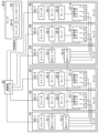
- (Application Example 3) 8 is a diagram showing a configuration (part 2) in which some devices of the communication system 100 according to the embodiment are housed in a rack.
- the communication system shown in FIG. 8 includes a plurality of servers 30, a controller 50, a plurality of switches 63, a plurality of main signal switches 67, a control switch 68, and a plurality of optical switches 70.
- FIG. 8 eight servers 30-1, 30-2, 30-3, 30-4, 30-5, 30-6, 30-7, and 30-8 are shown as the multiple servers 30; seven switches 63-1, 63-2, 63-3, 63-4, 63-5, 63-6, and 63-7 are shown as the multiple switches 63; four main signal switches 67-1, 67-2, 67-3, and 67-4 are shown as the multiple main signal switches 67; and four optical switches 70-1, 70-2, 70-3, and 70-4 are shown as the multiple optical switches 70. Note that there is no particular limit to the number of servers 30, switches 63, and optical switches 70.
- the multiple servers 30, the controller 50, the multiple switches 63, the multiple main signal switches 67, and the multiple optical switches 70 are housed in multiple racks R.
- Rack R1 houses the switch 63-1 and the optical switches 70-1 and 70-2.
- Rack R2 houses the switch 63-2, the servers 30-1 and 30-2, and the main signal switch 67-1.
- Rack R3 houses the switch 63-3, the servers 30-3 and 30-4, and the main signal switch 67-2.
- Rack R4 houses the switch 63-5 and the optical switches 70-3 and 70-4.
- Rack R5 houses the switch 63-6, the servers 30-5 and 30-6, and the main signal switch 67-3.
- Rack R6 houses the switch 63-7, the servers 30-7 and 30-8, and the main signal switch 67-4.
- Rack R10 houses the switch 63-4 and the controller 50.
- Racks R1, R2, and R3 are housed in a single housing.
- Racks R4, R5, and R6 are housed in a single housing.
- the racks R1, R2, R3, R4, R5, R6, and R10 are connected via the control switch 68.
- the switch 63 is a ToR switch.
- the switch 63 outputs an input signal to another path.
- the switch 63-1 is connected to the optical switches 70-1 and 70-2.
- the switch 63-1 is connected to the control switch 68.
- the switch 63-2 is connected to the servers 30-1 and 30-2.
- the switch 63-2 is connected to the control switch 68.
- the switch 63-3 is connected to the servers 30-3 and 30-4.
- the switch 63-3 is connected to the control switch 68.
- the switch 63-4 is connected to the controller 50.
- the switch 63-4 is connected to the control switch 68.
- Switch 63-5 is connected to optical switches 70-3 and 70-4. Furthermore, switch 63-5 is connected to control switch 68. Switch 63-6 is connected to servers 30-5 and 30-6. Furthermore, switch 63-6 is connected to control switch 68. Switch 63-7 is connected to servers 30-7 and 30-8. Furthermore, switch 63-7 is connected to control switch 68.
- the optical switch 70 outputs the input optical signal to another path.
- the optical switch 70 is connected to the main signal switch 67 and outputs the input main signal light to the main signal switch 67.
- the example shown in FIG. 8 shows a state in which the optical switch 70-2 is connected to the main signal switches 67-1, 67-2 and the optical switch 70-4, and the optical switch 70-4 is connected to the main signal switches 67-3, 67-4 and the optical switch 70-2.
- the optical switch 70-2 When the main signal is processed in any of the servers 30-1, 30-2, 30-3, and 30-4 housed in racks R2 and R3, the optical switch 70-2 outputs the input main signal light to the main signal switch 67-1 or the main signal switch 67-2.
- the optical switch 70-2 When the main signal is processed in any of the servers 30-5, 30-6, 30-7, and 30-8 housed in racks R5 and R6, the optical switch 70-2 outputs the input main signal light to the optical switch 70-4. This allows the optical switch 70-4 to transfer the main signal light to any of the servers 30-5, 30-6, 30-7, and 30-8 that process the main signal.
- the switching instruction for the path of the optical switch 70 is sent from the switching instruction unit 533 of the controller 50.
- the switching instruction unit 533 of the controller 50 generates a switching instruction for switching the path of the optical switch 70-2.
- the switching instruction unit 533 outputs the generated switching instruction to the switch 63-4 via the communication unit 51.
- the switch 63-4 transfers the input switching instruction to the control switch 68.
- the control switch 68 transfers the switching instruction transferred from the switch 63-4 to the switch 63 in the rack R in which the destination device is housed.
- the control switch 68 transfers the switching instruction transferred from the switch 63-4 to the switch 63-1 in the rack R1 in which the destination optical switch 70-2 is housed.
- the switch 63-1 transfers the switching instruction transferred from the control switch 68 to the destination optical switch 70-2. This allows the switching command to be transferred to optical switch 70-2.
- the main signal switch 67 is equipped with multiple transceivers T.
- the main signal switch 67 converts the optical main signal transferred from the optical switch 70 into an electrical signal using the transceivers T and transfers it to the server 30.
- the main signal switch 67 converts the electrical signal output from the server 30 into an optical signal using the transceivers T and transfers it to the optical switch 70.
- the switch 63 may also have the function of the main signal switch 67.
- the communication function 33 and the application 34 do not necessarily have to be housed on the same server 30.
- the switching instruction unit 533 instructs switching of the route so that the main signal is transferred via the following route.
- Optical switch 70-2 ⁇ optical switch 70-4 ⁇ main signal switch 67-3 ⁇ server 30-5 (communication function 33-5) ⁇ main signal switch 67-3 ⁇ optical switch 70-4 ⁇ main signal switch 67-4 ⁇ server 30-7 ⁇ main signal switch 67-4 ⁇ optical switch 70-4 ⁇ to upper NW 40
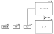
- (Application Example 4) 9 is a diagram showing a configuration in which a communication system 100 according to an embodiment is applied to a PON (Passive Optical Network) system.
- the PON system includes an ONU 80, an OLT 90, one or more servers 30, and a controller 50.
- the ONU 80 and the OLT 90 are connected by an optical transmission path such as an optical fiber.
- the ONU 80 is an optical subscriber line terminal that is installed in a user's premises and terminates optical signals.
- One or more terminal devices 60 are connected to the ONU 80.
- the ONU 80 converts the main signal transmitted from the terminal device 60 into an optical signal and outputs it to the optical transmission path.
- the OLT 90 is an optical subscriber line termination device provided on the electric utility side that terminates optical signals.
- the OLT 90 may accommodate multiple ONUs 80 via optical fibers and optical splitters.
- the OLT 90 receives optical signals transmitted from the ONUs 80.
- the OLT 90 converts the received optical signals into electrical signals and outputs them to the server 30.
- the OLT 90 notifies the controller 50 of traffic volume information. In this case, the traffic volume notified to the controller by the OLT 90 may be calculated based on the grant assigned to the ONUs 80.
- the specific processing of the PON system shown in FIG. 9 is the same as that shown in FIG. 1, and therefore will not be described.
- FIG. 10 is a diagram showing an example of another profile table 521.
- FIG. 10 shows an example of a profile table 521 in which the processing load of the communication function 33 depends on the number of connected terminal devices, and the processing load of the application 34 depends on the traffic volume. Therefore, FIG. 10 (A) registers the measurement results of the processing load for each number of connected terminal devices in the communication function 33, and FIG. 10 (B) registers the measurement results of the processing load for each traffic volume in the application 34.
- a part of the functions of the server 30 or the controller 50 in the above-mentioned embodiment may be realized by a computer.
- a program for realizing the function may be recorded on a computer-readable recording medium, and the program recorded on the recording medium may be read into the computer system and executed to realize the function.
- computer system here includes hardware such as an OS (Operating System) and peripheral devices.
- computer-readable recording medium refers to portable media such as flexible disks, optical magnetic disks, ROMs (Read Only Memory), and CD-ROMs, and storage devices such as hard disks built into the computer system.
- the term "computer-readable recording medium” may include a medium that dynamically holds a program for a short period of time, such as a communication line when transmitting a program via a network such as the Internet or a communication line such as a telephone line, and a medium that holds a program for a certain period of time, such as a volatile memory inside a computer system that is the server or client in such a case.
- the above-mentioned program may be a program for realizing a part of the above-mentioned functions, or may be a program that can realize the above-mentioned functions in combination with a program already recorded in the computer system, or may be a program that is realized using a programmable logic device such as an FPGA.
- the present invention can be applied to systems that provide computing resources for network functions and applications.
Landscapes
- Engineering & Computer Science (AREA)
- Computer Networks & Wireless Communication (AREA)
- Signal Processing (AREA)
- Data Exchanges In Wide-Area Networks (AREA)
Priority Applications (2)
| Application Number | Priority Date | Filing Date | Title |
|---|---|---|---|
| PCT/JP2023/016443 WO2024224507A1 (ja) | 2023-04-26 | 2023-04-26 | 制御装置及びリソース割当方法 |
| JP2025516373A JPWO2024224507A1 (https=) | 2023-04-26 | 2023-04-26 |
Applications Claiming Priority (1)
| Application Number | Priority Date | Filing Date | Title |
|---|---|---|---|
| PCT/JP2023/016443 WO2024224507A1 (ja) | 2023-04-26 | 2023-04-26 | 制御装置及びリソース割当方法 |
Publications (1)
| Publication Number | Publication Date |
|---|---|
| WO2024224507A1 true WO2024224507A1 (ja) | 2024-10-31 |
Family
ID=93256155
Family Applications (1)
| Application Number | Title | Priority Date | Filing Date |
|---|---|---|---|
| PCT/JP2023/016443 Ceased WO2024224507A1 (ja) | 2023-04-26 | 2023-04-26 | 制御装置及びリソース割当方法 |
Country Status (2)
| Country | Link |
|---|---|
| JP (1) | JPWO2024224507A1 (https=) |
| WO (1) | WO2024224507A1 (https=) |
Citations (3)
| Publication number | Priority date | Publication date | Assignee | Title |
|---|---|---|---|---|
| WO2015041750A1 (en) * | 2013-09-23 | 2015-03-26 | Oracle International Corporation | Methods, systems, and computer readable media for diameter load and overload information and virtualization |
| WO2015116449A1 (en) * | 2014-01-28 | 2015-08-06 | Oracle International Corporation | Methods, systems, and computer readable media for a cloud-based virtualization orchestrator |
| JP2018129775A (ja) * | 2017-02-10 | 2018-08-16 | 日本電信電話株式会社 | 通信装置、通信方法及び通信プログラム |
-
2023
- 2023-04-26 JP JP2025516373A patent/JPWO2024224507A1/ja active Pending
- 2023-04-26 WO PCT/JP2023/016443 patent/WO2024224507A1/ja not_active Ceased
Patent Citations (3)
| Publication number | Priority date | Publication date | Assignee | Title |
|---|---|---|---|---|
| WO2015041750A1 (en) * | 2013-09-23 | 2015-03-26 | Oracle International Corporation | Methods, systems, and computer readable media for diameter load and overload information and virtualization |
| WO2015116449A1 (en) * | 2014-01-28 | 2015-08-06 | Oracle International Corporation | Methods, systems, and computer readable media for a cloud-based virtualization orchestrator |
| JP2018129775A (ja) * | 2017-02-10 | 2018-08-16 | 日本電信電話株式会社 | 通信装置、通信方法及び通信プログラム |
Also Published As
| Publication number | Publication date |
|---|---|
| JPWO2024224507A1 (https=) | 2024-10-31 |
Similar Documents
| Publication | Publication Date | Title |
|---|---|---|
| RU2643626C1 (ru) | Способ распределения принимаемых пакетов, селектор очереди, устройство обработки пакетов и носитель информации | |
| US8270295B2 (en) | Reassigning virtual lane buffer allocation during initialization to maximize IO performance | |
| JP4416053B1 (ja) | Ponシステム、ponシステムにおける局側装置およびその制御方法 | |
| CN114040467A (zh) | 一种传输路径的确定方法、装置、服务器及存储介质 | |
| US20160147548A1 (en) | Virtual machine arrangement design apparatus and method , system, and program | |
| JP6394695B2 (ja) | 局側装置、通信制御方法および通信制御プログラム | |
| US10374875B2 (en) | Resource management device, resource management system, and computer-readable recording medium | |
| CN108141403B (zh) | 中继传输系统、中继传输方法以及中继传输装置 | |
| CN112737806B (zh) | 网络流量的迁移方法及装置 | |
| US20160019086A1 (en) | Apparauts and method for generating software defined network(sdn)-based virtual network according to user demand | |
| JP2003087282A (ja) | 動的帯域割当回路、動的帯域割当方法、動的帯域割当プログラムおよび記録媒体 | |
| WO2024224507A1 (ja) | 制御装置及びリソース割当方法 | |
| CN106331904B (zh) | 无源光纤网络中波长通道的分配方法、光线路终端及系统 | |
| CN114024796B (zh) | 一种数据发送方法、通信装置和电子设备 | |
| CN108141345B (zh) | 传输系统、传输方法以及传输装置 | |
| WO2018057165A1 (en) | Technologies for dynamically transitioning network traffic host buffer queues | |
| CN114064288B (zh) | 用于分布式存储系统的数据链路分配方法、装置和设备 | |
| WO2023095298A1 (ja) | 管理装置、管理方法、及び、管理プログラム | |
| JP2000349813A (ja) | パケット交換網システム | |
| EP2939382B1 (en) | Distributed data processing system | |
| JP7541252B2 (ja) | 光通信装置、制御方法および光通信システム | |
| JP4741410B2 (ja) | 移動体通信システム、交換機、基地局装置、及び下り通信データ送信方法 | |
| JP6667428B2 (ja) | 光伝送装置、光集線ネットワークシステム及びデータ送信指示方法 | |
| CN102546075B (zh) | 多时分配置方法及装置 | |
| CN121770998A (zh) | 连接跟踪方法、装置和网络设备 |
Legal Events
| Date | Code | Title | Description |
|---|---|---|---|
| 121 | Ep: the epo has been informed by wipo that ep was designated in this application |
Ref document number: 23935287 Country of ref document: EP Kind code of ref document: A1 |
|
| ENP | Entry into the national phase |
Ref document number: 2025516373 Country of ref document: JP Kind code of ref document: A |
|
| WWE | Wipo information: entry into national phase |
Ref document number: 2025516373 Country of ref document: JP |
|
| NENP | Non-entry into the national phase |
Ref country code: DE |
|
| 122 | Ep: pct application non-entry in european phase |
Ref document number: 23935287 Country of ref document: EP Kind code of ref document: A1 |