WO2024219394A1 - 回転体取り付け構造、及び投写型映像表示装置 - Google Patents
回転体取り付け構造、及び投写型映像表示装置 Download PDFInfo
- Publication number
- WO2024219394A1 WO2024219394A1 PCT/JP2024/015127 JP2024015127W WO2024219394A1 WO 2024219394 A1 WO2024219394 A1 WO 2024219394A1 JP 2024015127 W JP2024015127 W JP 2024015127W WO 2024219394 A1 WO2024219394 A1 WO 2024219394A1
- Authority
- WO
- WIPO (PCT)
- Prior art keywords
- rotating body
- hole
- light
- sleeve
- screw
- Prior art date
- Legal status (The legal status is an assumption and is not a legal conclusion. Google has not performed a legal analysis and makes no representation as to the accuracy of the status listed.)
- Ceased
Links
Images



Classifications
-
- G—PHYSICS
- G03—PHOTOGRAPHY; CINEMATOGRAPHY; ANALOGOUS TECHNIQUES USING WAVES OTHER THAN OPTICAL WAVES; ELECTROGRAPHY; HOLOGRAPHY
- G03B—APPARATUS OR ARRANGEMENTS FOR TAKING PHOTOGRAPHS OR FOR PROJECTING OR VIEWING THEM; APPARATUS OR ARRANGEMENTS EMPLOYING ANALOGOUS TECHNIQUES USING WAVES OTHER THAN OPTICAL WAVES; ACCESSORIES THEREFOR
- G03B21/00—Projectors or projection-type viewers; Accessories therefor
- G03B21/14—Details
- G03B21/20—Lamp housings
- G03B21/2006—Lamp housings characterised by the light source
- G03B21/2033—LED or laser light sources
- G03B21/204—LED or laser light sources using secondary light emission, e.g. luminescence or fluorescence
-
- F—MECHANICAL ENGINEERING; LIGHTING; HEATING; WEAPONS; BLASTING
- F21—LIGHTING
- F21S—NON-PORTABLE LIGHTING DEVICES; SYSTEMS THEREOF; VEHICLE LIGHTING DEVICES SPECIALLY ADAPTED FOR VEHICLE EXTERIORS
- F21S2/00—Systems of lighting devices, not provided for in main groups F21S4/00 - F21S10/00 or F21S19/00, e.g. of modular construction
-
- F—MECHANICAL ENGINEERING; LIGHTING; HEATING; WEAPONS; BLASTING
- F21—LIGHTING
- F21V—FUNCTIONAL FEATURES OR DETAILS OF LIGHTING DEVICES OR SYSTEMS THEREOF; STRUCTURAL COMBINATIONS OF LIGHTING DEVICES WITH OTHER ARTICLES, NOT OTHERWISE PROVIDED FOR
- F21V9/00—Elements for modifying spectral properties, polarisation or intensity of the light emitted, e.g. filters
- F21V9/30—Elements containing photoluminescent material distinct from or spaced from the light source
- F21V9/32—Elements containing photoluminescent material distinct from or spaced from the light source characterised by the arrangement of the photoluminescent material
- F21V9/35—Elements containing photoluminescent material distinct from or spaced from the light source characterised by the arrangement of the photoluminescent material at focal points, e.g. of refractors, lenses, reflectors or arrays of light sources
-
- F—MECHANICAL ENGINEERING; LIGHTING; HEATING; WEAPONS; BLASTING
- F21—LIGHTING
- F21V—FUNCTIONAL FEATURES OR DETAILS OF LIGHTING DEVICES OR SYSTEMS THEREOF; STRUCTURAL COMBINATIONS OF LIGHTING DEVICES WITH OTHER ARTICLES, NOT OTHERWISE PROVIDED FOR
- F21V9/00—Elements for modifying spectral properties, polarisation or intensity of the light emitted, e.g. filters
- F21V9/30—Elements containing photoluminescent material distinct from or spaced from the light source
- F21V9/38—Combination of two or more photoluminescent elements of different materials
-
- F—MECHANICAL ENGINEERING; LIGHTING; HEATING; WEAPONS; BLASTING
- F21—LIGHTING
- F21V—FUNCTIONAL FEATURES OR DETAILS OF LIGHTING DEVICES OR SYSTEMS THEREOF; STRUCTURAL COMBINATIONS OF LIGHTING DEVICES WITH OTHER ARTICLES, NOT OTHERWISE PROVIDED FOR
- F21V9/00—Elements for modifying spectral properties, polarisation or intensity of the light emitted, e.g. filters
- F21V9/40—Elements for modifying spectral properties, polarisation or intensity of the light emitted, e.g. filters with provision for controlling spectral properties, e.g. colour, or intensity
-
- G—PHYSICS
- G03—PHOTOGRAPHY; CINEMATOGRAPHY; ANALOGOUS TECHNIQUES USING WAVES OTHER THAN OPTICAL WAVES; ELECTROGRAPHY; HOLOGRAPHY
- G03B—APPARATUS OR ARRANGEMENTS FOR TAKING PHOTOGRAPHS OR FOR PROJECTING OR VIEWING THEM; APPARATUS OR ARRANGEMENTS EMPLOYING ANALOGOUS TECHNIQUES USING WAVES OTHER THAN OPTICAL WAVES; ACCESSORIES THEREFOR
- G03B21/00—Projectors or projection-type viewers; Accessories therefor
-
- G—PHYSICS
- G03—PHOTOGRAPHY; CINEMATOGRAPHY; ANALOGOUS TECHNIQUES USING WAVES OTHER THAN OPTICAL WAVES; ELECTROGRAPHY; HOLOGRAPHY
- G03B—APPARATUS OR ARRANGEMENTS FOR TAKING PHOTOGRAPHS OR FOR PROJECTING OR VIEWING THEM; APPARATUS OR ARRANGEMENTS EMPLOYING ANALOGOUS TECHNIQUES USING WAVES OTHER THAN OPTICAL WAVES; ACCESSORIES THEREFOR
- G03B21/00—Projectors or projection-type viewers; Accessories therefor
- G03B21/14—Details
-
- H—ELECTRICITY
- H04—ELECTRIC COMMUNICATION TECHNIQUE
- H04N—PICTORIAL COMMUNICATION, e.g. TELEVISION
- H04N5/00—Details of television systems
- H04N5/74—Projection arrangements for image reproduction, e.g. using eidophor
-
- F—MECHANICAL ENGINEERING; LIGHTING; HEATING; WEAPONS; BLASTING
- F21—LIGHTING
- F21Y—INDEXING SCHEME ASSOCIATED WITH SUBCLASSES F21K, F21L, F21S and F21V, RELATING TO THE FORM OR THE KIND OF THE LIGHT SOURCES OR OF THE COLOUR OF THE LIGHT EMITTED
- F21Y2115/00—Light-generating elements of semiconductor light sources
- F21Y2115/30—Semiconductor lasers
Definitions
- This disclosure relates to a rotating body mounting structure for mounting a rotating body.
- This disclosure also relates to a rotating body mounting structure for mounting an optical rotating body such as a phosphor wheel or a color wheel, and a projection-type image display device including the rotating body mounting structure.
- Rotating bodies that rotate by driving the rotation shaft are used in rotating equipment such as mixers and fans.
- Optical rotating bodies such as phosphor wheels or color wheels are used in optical devices such as projection-type image display devices. Fixing devices for mounting these rotating bodies are disclosed in, for example, Patent Document 1.
- Patent Document 1 the rotating body is attached to the rotating body mounting part so that it can rotate around the rotation axis and is positioned in the axial direction, and is fixed by tightening a nut.
- Patent Document 1 makes it possible to ensure sufficient fixing force for the rotating body by preventing the fixing nut from loosening even when the rotating body rotates in the reverse direction.
- a rotor fixing structure such as that of Patent Document 1
- the rotor is fixed to the rotor mounting part by directly contacting a screw part such as a nut.
- vibrations of the motor are transmitted directly to the rotor mounting part via the screw part while the rotor is rotating.
- These vibrations can be further amplified by resonating with surrounding mechanical parts, resulting in loud noise.
- optical rotors such as phosphor wheels or color wheels used in projection-type image display devices have the challenge of maintaining installation precision while suppressing noise caused by motor vibration.
- the present disclosure aims to solve the above-mentioned problems in the past and provide a rotating body mounting structure that can suppress noise caused by vibrations during rotation of the rotating body.
- a rotating body mounting structure for mounting a rotating body having a threaded hole formed in the mounting surface to a support having a mounting hole penetrating in the axial direction of the rotating shaft of the rotating body, the rotating body mounting structure comprising an elastic member having an axial through hole and fitted into the mounting hole, and a fixing member inserted into the through hole, the fixing member including a central portion disposed in the axial direction within the through hole of the elastic member, a tip portion exposed from the through hole on the mounting surface side, and a rear end portion exposed from the through hole on the opposite side of the mounting surface, the tip portion having a thread formed therein for engaging with the threaded hole, and the rear end portion having a first wall surface intersecting the axial direction, and when the tip portion is screwed into the threaded hole, the elastic member is compressed between the mounting surface and the first wall surface.
- the rotating body mounting structure according to one aspect of the present disclosure can suppress noise caused by vibrations during rotation of the rotating body.
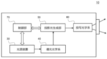
- FIG. 1 is a diagram showing an overall configuration of a projection-type image display device according to a first embodiment
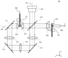
- FIG. 2 is a schematic diagram of a light source device in the projection type image display device of FIG. 1
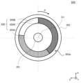
- FIG. 3 is a diagram showing an example of the configuration of a light receiving surface of a phosphor wheel in the light source device of FIG. 2
- FIG. 3 is a diagram showing an example of the configuration of a light receiving surface of a color wheel in the light source device of FIG. 2
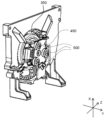
- FIG. 1 is an exploded perspective view showing the attachment of a phosphor wheel using a rotating body attachment structure according to a first embodiment of the present invention
- FIG. 1 is a cross-sectional view showing a configuration of a rotating body mounting structure according to a first embodiment.
- FIG. 11 is a cross-sectional view showing a configuration of a rotating body mounting structure according to a modified example of the first embodiment.
- FIG. 11 is a cross-sectional view showing the configuration of a rotating body mounting structure according to a second embodiment.
- Schematic diagram showing the noise measurement arrangement for a projection type image display device Graph showing noise measurement results due to vibration during phosphor wheel rotation
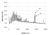
- Graph showing the results of measuring noise caused by vibrations while rotating a color wheel
- a rotating body mounting structure for mounting a rotating body having a threaded hole formed in the mounting surface to a support having a mounting hole penetrating in the axial direction of the rotating shaft of the rotating body
- the rotating body mounting structure comprising an elastic member having an axial through hole and fitted into the mounting hole, and a fixing member inserted into the through hole, the fixing member including a central portion disposed in the axial direction within the through hole of the elastic member, a tip portion exposed from the through hole on the mounting surface side, and a rear end portion exposed from the through hole on the opposite side of the mounting surface, the tip portion having a thread formed therein for engaging with the threaded hole, and the rear end portion having a first wall surface intersecting the axial direction, the elastic member being compressed between the mounting surface and the first wall surface when the tip portion is screwed into the threaded hole.
- This aspect provides a rotor mounting structure that can suppress noise caused by vibrations during rotation of the rotor.
- the fixing member further has a second wall surface that intersects with the axial direction at the boundary between the tip portion and the central portion, and when the tip portion is screwed into the screw hole, the second wall surface abuts against the mounting surface, providing the rotating body mounting structure described in the first aspect.
- the fixing member includes a sleeve and a screw member, a portion of which is inserted into the sleeve, the sleeve includes a first portion disposed within the through hole and a second portion exposed from the through hole on the side opposite the mounting surface, the screw member has a tip portion exposed from the sleeve on the mounting surface side and a head portion exposed from the sleeve on the side opposite the mounting surface, and when the tip portion of the screw member is screwed into the threaded hole, the second portion of the sleeve constitutes the first wall surface.
- a rotating body mounting structure as described in the first or second aspect, in which the fixing member includes a sleeve and a screw member, a portion of which is inserted into the sleeve, the sleeve is disposed within the through hole, the screw member has a tip portion exposed from the sleeve on the mounting surface side and a head portion exposed from the sleeve on the opposite side of the mounting surface, and when the tip portion of the screw member is screwed into the threaded hole, the head portion forms the first wall surface.
- a rotating body mounting structure as described in the third or fourth aspect, in which, when the tip of the screw member is screwed into the screw hole, the end of the sleeve on the mounting surface side abuts against the mounting surface, and the end on the opposite side of the mounting surface abuts against the head.
- the fixing member is integrally formed and includes a threaded portion having a thread formed thereon, an expanded diameter portion having an outer diameter larger than the outer diameter of the thread, and a wall surface end portion having a diameter larger than the outer diameter of the expanded diameter portion, the expanded diameter portion being between the threaded portion and the wall surface end portion, and being inserted into the through hole, the wall surface end portion forms a first wall surface at the boundary with the expanded diameter portion when the threaded portion is screwed into the screw hole.
- a rotating body mounting structure as described in the sixth aspect, in which, when the threaded portion is screwed into the threaded hole, the end of the enlarged diameter portion at the boundary between the enlarged diameter portion and the threaded portion abuts against the mounting surface.
- a rotating body mounting structure according to any one of the first to seventh aspects, in which the elastic member has a recess formed along the circumferential direction on the outer circumferential surface, and the support member around the mounting hole is fitted into the recess.
- a rotating body mounting structure according to any one of the first to eighth aspects, in which the fixing member is made of a material containing metal.
- a rotating body mounting structure according to any one of the first to ninth aspects, in which the elastic member is made of a material containing, for example, ACM rubber.
- a rotating body mounting structure according to any one of the first to tenth aspects is provided, in which the rotating body constitutes a phosphor wheel that converts incident light into light of different wavelengths and emits the light, or a color wheel that transmits incident light in multiple color bands and emits the light.
- a light source device including a light source that emits incident light, and a phosphor wheel that converts the incident light into light of different wavelengths and emits the light, or a color wheel that transmits the incident light in multiple color bands and emits the light, attached using a rotating body attachment structure described in any one of the first to eleventh aspects.
- a projection type image display device comprising the light source device according to claim 12, a projection light generating unit that generates projection light in accordance with a video signal, a light guide optical system that guides the illumination light emitted from the light source device to the projection light generating unit, and a projection optical system that enlarges and projects the projection light from the projection light generating unit to display an image.
- Fig. 1 is a diagram showing the overall configuration of a projection-type image display device 10 according to the first embodiment.
- the projection type image display device 10 includes a light source device 30, a light guide optical system 40, a projection light generating unit 50, a projection optical system 60, and a control unit 70.
- the projection type image display device 10 generates projection light in the projection light generating unit 50 according to an input video signal based on the light emitted by the light source device 30, and projects the projection light generated by the projection optical system 60 onto a projection target such as an external screen to display an image.
- the light source device 30 has a solid-state light source such as a semiconductor laser and a phosphor, and emits light under the control of the control unit 70.
- the light source device 30 can be equipped with an illumination optical system that includes a light source and one or both of a phosphor wheel and a color wheel (described in detail below). The configuration of the light source device 30 will be described in detail below.
- the light-guiding optical system 40 guides the light emitted from the light source device 30 to the projection light generating unit 50.
- the light-guiding optical system 40 is configured by appropriately arranging various optical components such as lenses, mirrors, and rods.
- the projection light generating unit 50 includes a spatial light modulation element (not shown) such as a digital micromirror device or a liquid crystal panel.
- the projection light generating unit 50 uses the spatial light modulation element to modulate the incident light according to the video signal.
- the projection optical system 60 guides the light emitted from the projection light generating unit 50 to the projection lens 10, and projects an enlarged image based on the light spatially modulated by the projection light generating unit 50 via the projection lens 10.
- the projection optical system 60 is composed of various optical components such as various lenses and mirrors.
- the control unit 70 controls the overall operation of the projection type image display device 10.
- the control unit 70 can include, for example, a video input terminal (not shown) for inputting a video signal from the outside, and various drivers (not shown).
- the various drivers can include, for example, a light source driver, a wheel driver, and a display device driver.
- the light source driver drives the light emission operation of the light source in the light source device 30, the wheel driver drives the rotation of the phosphor wheel and color wheel provided in the light source device 30, and the display device driver can supply a video signal to the spatial light modulation element in the projection light generation unit 50 and drive the spatial light modulation element.
- the various functions of the control unit 70 may be incorporated into each component of the projection type image display device 10.
- Fig. 2 is a schematic diagram of the light source device 30 in the projection-type image display device 10 of Fig. 1.
- light source device 30 including a phosphor wheel 350 and a color wheel 370 will be described as an example of a light source device that generates white light from blue light from a light source.
- Fig. 2 shows the configuration of light source device 30 on the XY plane.
- the light source device 30 includes a laser light source 301, a dichroic mirror 310, focusing lenses 321, 322, and 323, mirrors 311, 312, and 313, lenses 331, 332, and 333, a phosphor wheel 350, a color wheel 370, and a rod integrator 380.
- the laser light source 301 emits blue laser light.
- the laser light source 301 may be configured to include multiple semiconductor laser elements.
- the blue laser light from the laser light source 301 travels along the optical axis Oa and enters the dichroic mirror 310 that is arranged at an inclination angle of approximately 45 degrees with respect to the optical axis Oa.
- Dichroic mirror 310 has the property of reflecting the blue laser light from laser light source 301 and transmitting light in other wavelength ranges.
- the blue laser light incident in the -X direction in the figure is reflected by dichroic mirror 310, emitted in the +Y direction in the figure, travels along optical axis Ob, is focused by focusing lens 321, and enters phosphor wheel 350.
- FIG. 3 is a diagram showing an example of the configuration of the light receiving surface of the phosphor wheel 350 in the light source device 30 of FIG. 2.
- the phosphor wheel 350 is configured to emit, in a time-division manner by rotation, blue light that has passed through the blue laser light of the laser light source 301, and fluorescent light that has been converted from the blue laser light of the laser light source 301 into light of different wavelengths.
- phosphor wheel 350 includes disk-shaped substrate 352 that is rotated by a motor (not shown in FIG. 3) via a central shaft 351.
- Substrate 352 can be rotated around shaft 351 along the illustrated rotation direction A by the drive of the motor, about rotation axis O1. By rotating substrate 352, it is possible to suppress a temperature rise of the phosphor layer on substrate 352 due to excitation light, and to maintain a stable wavelength conversion efficiency.
- an annular region 355 is formed on the light receiving surface 352a of the substrate 352, and the annular region 355 is composed of an opening region 355B and phosphor layer regions 355R and 355G.
- the opening region 355B transmits the incident blue laser light.
- the phosphor layer regions 355R and 355G have phosphor layers formed therein that are excited by the incident blue laser light to emit fluorescent light.
- the phosphor layer region includes a red phosphor layer region 355R and a green phosphor layer region 355G formed along the circumferential direction, and are excited by the incident blue laser light to emit red fluorescent light and green fluorescent light, respectively.
- annular region 355 is shown to have two types of phosphor layer regions, but the present disclosure is not limited to this.
- annular region 355 of phosphor wheel 350 can also be configured to have one type, or three or more types of phosphor layer regions.
- the blue laser light passes through the focusing lens 320 due to the rotation of the phosphor wheel 350, the blue light passes through and exits when it enters the opening region 355B, and when it enters the phosphor layer regions 355R and 355G, it excites the phosphor to emit red and green fluorescent light.
- the red fluorescent light and green fluorescent light generated in phosphor layer regions 355R and 355G of phosphor wheel 350 are reflected from phosphor wheel 350 in the -Y direction, pass through condenser lens 320, transmit through dichroic mirror 310, and proceed along optical axis Ob.
- the blue light that passes through opening region 355B of phosphor wheel 350 passes through lens 322, proceeds along a path of mirror 311, lens 331, mirror 312, lens 332, mirror 313, and lens 333, is reflected by dichroic mirror 310, and is emitted along optical axis Ob.
- the blue light, red fluorescent light, and green fluorescent light emitted from dichroic mirror 310 in the -Y direction along optical axis Ob pass through condenser lens 323 and enter color wheel 370.
- the color wheel 370 is configured to receive the yellow fluorescent light and blue light transmitted through the condenser lens 330 from the phosphor wheel 350, transmit the light in multiple color bands as it rotates, and emit the light in a time-division manner.
- the configuration of the color wheel 370 will be described with reference to FIG. 4.
- FIG. 4 is a diagram showing an example of the configuration of the light receiving surface of the color wheel 370 in the light source device 30 of FIG. 2.
- the color wheel 370 is driven by a motor (not shown) and includes a disk-shaped transparent substrate 372 that rotates around a central shaft 371.
- Dichroic layers 375G, 375R, and an anti-reflection layer 375B are formed on the light receiving surface 372a of the transparent substrate 372 shown in FIG. 4.
- Transparent substrate 372 has three color light segments SR, SG, and SB in the circumferential direction.
- color light segment SB of color wheel 370 has an angle corresponding to opening region 355B (see FIG. 3) of phosphor wheel 350
- color light segments SR and SG have angles corresponding to phosphor layer regions 355R and 355G (see FIG. 3) of phosphor wheel 350, respectively.
- a dichroic layer 375R that transmits red light is formed in the color light segment SR
- a dichroic layer 375G that transmits green light is formed in the color light segment SG
- the color wheel 370 is controlled by the control unit 70 (see FIG. 1) to rotate synchronously with the phosphor wheel 350 around the rotation axis O2 along the rotation direction B.
- the dichroic layer 375R is on the optical axis Ob during the period when the blue laser light, which is the excitation light incident on the phosphor wheel 350, is incident on the phosphor layer region 355R that emits red fluorescent light
- the dichroic layer 375G is on the optical axis Ob during the period when the blue laser light, which is the excitation light, is incident on the phosphor layer region 355G that emits green fluorescent light
- the anti-reflection layer 375B is on the optical axis Ob during the period when the blue laser light is incident on the opening region 355B.
- the light in the red, green, and blue wavelength bands that enters the rod integrator 380 is reflected multiple times inside the rod integrator 380, and the light intensity distribution is homogenized and the light is emitted from the light source device 30 as white illumination light Li.
- the light source device 30 shown in FIG. 2 is an example configuration including both the phosphor wheel 350 and the color wheel 370, the present disclosure is not limited to this.
- the light source device 30 may be configured not to include the color wheel 370.
- the light source device in the projection type image display device according to this embodiment may be configured by adopting various light source device arrangements known in the art. A detailed description thereof will be omitted here.
- Fig. 5 is a perspective view showing the attachment of phosphor wheel 350.
- Fig. 6 is a perspective view showing the attachment of color wheel 370.
- Fig. 7 is a side view showing the attachment of phosphor wheel 350.
- the phosphor wheel 350 and the color wheel 370 are attached to the support surface 450 of the phosphor wheel holder and the support surface 470 of the color wheel holder, respectively, by a rotor mounting structure 500.
- the phosphor wheel 350 or the color wheel 370 is attached using three rotor mounting structures 500, but the present disclosure is not limited to the number of rotor mounting structures used for attachment.
- the phosphor wheel 350 comprises a substrate 352 and a motor 360.
- the phosphor wheel 350 is an example of a rotating body in this embodiment.
- the color wheel 370 has substantially the same rotational configuration as the phosphor wheel 350, but differs from the substrate 352 of the phosphor wheel 350 (see FIG. 3) in the configuration of the transparent substrate 372 (see FIG. 4). A detailed description of the rotational configuration of the color wheel 370 will be omitted.
- the substrate 352 of the phosphor wheel 350 is a disk-shaped metal substrate made of a thermally conductive material such as aluminum.
- An annular region including a phosphor layer region is formed on the light receiving surface 352a of the substrate 352 ( Figure 3).
- a motor 360 is attached to the surface 352b opposite the light receiving surface 352a of the substrate 352.
- the substrate 352 constitutes the rotation surface of the phosphor wheel 350.
- the motor 360 is composed of a rotor 361 and a stator 362.
- the rotor 361 is attached to a surface 352b of the substrate 352 of the phosphor wheel 350, and is integral with the rotating surface of the phosphor wheel 350.
- the stator 362 supports the rotor 361 via the shaft 351. When the motor 360 is driven, the substrate 352 and the rotor 361 of the phosphor wheel 350 can rotate integrally around the shaft 351, centering on the rotation axis O1.
- the motor 360 is attached to the support surface 450 of the phosphor wheel holder 400, which is the rotor support body, at the mounting surface 360a of the stator 362 using a rotor mounting structure 500.
- the rotor mounting structure 500 not only allows the phosphor wheel 350 to engage with the phosphor wheel holder 400 and rotate stably, but also allows accurate positioning in the direction of the rotation axis O1 and suppresses noise caused by vibration during operation of the rotor.
- the configuration of the rotor mounting structure 500 of the present disclosure is described below.
- Fig. 8 is an exploded perspective view showing the mounting of the phosphor wheel 350 using the rotor mounting structure 500A according to the first embodiment.
- Fig. 9A is a cross-sectional view showing the configuration of the rotor mounting structure 500A according to the first embodiment.
- Fig. 9B is a cross-sectional view showing the configuration of the rotor mounting structure 500A1 according to a modified example of the first embodiment.
- Fig. 10 is a cross-sectional view showing the configuration of the rotor mounting structure 500B according to the second embodiment.
- the motor 360 of the phosphor wheel 350 has a screw hole 365 formed in the mounting surface 360a
- the support surface 450 of the phosphor wheel holder 400 has a mounting hole 455 formed therethrough in the direction of the mounting axis O1a that is parallel to the rotation axis of the phosphor wheel 350.
- the rotating body mounting structure 500A attaches the phosphor wheel 350 to the phosphor wheel holder 400 by threading the mounting hole 455 through the screw hole 365 along the mounting axis O1a.
- the rotating body mounting structure 500A includes an elastic member 510 and a fixing member 520A, and the fixing member 520A is configured by a sleeve 505 and a screw member 506. As shown in Fig. 9A, the elastic member 510 has a through hole 515 in the direction of the mounting axis O1a, and the fixing member 520A is inserted into the through hole 515.
- the elastic member 510 is fitted into the mounting hole 455 in the support surface 450 of the phosphor wheel holder 400 and is interposed between the mounting surface 360a of the phosphor wheel 350 and the support surface 450 of the phosphor wheel holder 400. This dampens vibrations during rotation of the phosphor wheel 350, suppresses transmission of the vibrations to the phosphor wheel holder 400, and reduces noise caused by vibrations.
- the elastic member 510 can be composed of, for example, a bush made of an elastic material.
- the elastic material that composes the elastic member 510 can be selected so that it has a sufficiently low transmissibility with respect to noise frequencies that may be generated by the rotation of the rotating body.
- factors such as the operating environment of the rotating body can be taken into consideration, and an elastic material that is suitable for the operating environment can be used.
- an elastic material constituting the elastic member 510 can be selected so that the transmissibility for noise frequencies around 3000 Hz is less than 1.
- a material can be used that has sufficient mechanical strength and heat resistance in the operating environment of the phosphor wheel or color wheel, and is relatively unlikely to change or deteriorate due to exposure to light.
- the elastic member 510 can be formed using a bush made of ACM rubber (acrylic rubber).
- a through hole 515 is formed in the elastic member 510 in the direction of the mounting axis O1a, and the fixing member 520A is inserted into the through hole 515.
- the fixing member 520A is a rigid member made of a material containing metal, for example, and can include a central portion 522A arranged in the through hole 515 in the direction of the mounting axis O1a, and a tip portion 521A on the mounting surface 360a side and a rear end portion 523A on the opposite side of the mounting surface 360a, which are exposed from the through hole 515.
- the tip portion 521A of the fixing member 520A is threaded and can be screwed into a screw hole 365 in the mounting surface 360a of the motor 360.
- the central portion 522A and rear end portion 523A of the fixing member 520A include two wall surfaces 500a, 500b that intersect with the direction of the mounting axis O1a, allowing the fixing member 520A to be precisely positioned when screwed together, and also forming an interposition surface 500c between the mounting surface of the rotating body and the support surface of the support body, providing a space for interposing the elastic member 510.
- the fixing member 520A of the rotating body mounting structure 500A of this embodiment is composed of a sleeve 505 and a screw member 506.
- the sleeve 505 has two ends 505a, 505b, and a through channel 525 is formed in the center in the direction of the mounting axis O1a.
- the end 505a of the sleeve 505 can be inserted into the through hole 515 of the elastic member 510, and the end 505b has a large area in a direction intersecting the direction of the mounting axis O1a, cannot be inserted into the through hole 515, and is exposed from the through hole 515.
- both ends 505a, 505b of the sleeve 505 form the two wall surfaces 500a, 500b of the fixing member 520A, and the portion inserted into the through hole 515 between the ends 505a, 505b forms the intermediate surface 500c.
- the wall surfaces 500a, 500b are configured to be approximately perpendicular to the direction of the mounting axis O1a.
- the screw member 506 has a tip 506a with a thread formed thereon and a head 506b.
- the tip 506a is inserted into the through channel 525 from the end 505b of the sleeve 505 and is exposed from the sleeve 505 on the mounting surface 360a side.
- the head 506b is configured so as not to be insertable into the sleeve 505 and is exposed from the sleeve 505 on the opposite side of the mounting surface 360a.
- the screw member 506 can be inserted into the through channel 525 until the head 506b abuts against the end 505b of the sleeve 505, at which time the tip 506a of the screw member 506 protrudes from the end 505a of the sleeve 505 and can be screwed into the threaded hole 365 in the mounting surface 360a of the motor 360.
- the tip 506a of the screw member 506 constitutes the tip portion 521A of the fixing member 520A.
- the end 505a of the sleeve 505 abuts against the mounting surface 360a at the wall surface 500a, and the end 500b abuts against the head 506b of the screw member 506.
- the length L between the two ends 505a, 505b of the sleeve 505 allows the fixing member 520A to be precisely positioned in the direction of the mounting axis O1a of the fixing member 520A.
- the rotating body When mounting an optical rotating body such as a phosphor wheel or a color wheel on a support, it is desirable to mount the rotating body on the support surface so that the rotation plane of the rotating body is perpendicular to the rotation axis in order to ensure rotational stability and an accurate light propagation path.
- the phosphor wheel 350 and the color wheel 370 are mounted on the supports 450, 470 using a plurality of rotating body mounting structures 500. By aligning the positioning of the screwing direction by each rotating body mounting structure, the phosphor wheel or color wheel can be mounted so that the rotation plane is perpendicular to the rotation axis.
- a sleeve 505 which is a rigid member
- the elastic member 510 by inserting a sleeve 505, which is a rigid member, into the elastic member 510 and positioning it in the direction of the mounting axis O1a, it is possible to suppress dimensional variations due to individual differences in parts during processing and variations due to differences in the tightening force during mounting, and ensure the accuracy of positioning in the direction of the mounting axis O1a.
- the length L between both ends 505a, 505b of the sleeve 505 allows the phosphor wheel to be attached with high precision so that the positioning tolerance is within ⁇ 0.1 mm in the direction of the mounting axis O1a.
- a space is formed between the mounting surface 360a of the motor 360 and the wall surface 500b of the end 505b of the sleeve 505, in which the elastic member 510 is interposed.
- the inner circumferential surface 510c of the through hole 515 of the elastic member 510 is disposed in contact with the interposed surface 500c formed by the part of the sleeve 505 inserted into the through hole 515.
- a recess 511 is formed along the circumferential direction on the outer circumferential surface 510d of the elastic member 510, and the support member 456 around the mounting hole 455 of the support surface 450 is disposed so as to fit into the recess 511 of the outer circumferential surface 510d of the elastic member 510.
- the recess 511 can be configured in any shape, and the present disclosure is not limited thereto.
- the inner surface of the recess 511 may be configured as a flat surface or a curved surface.
- the elastic member 510 can be configured to have a length greater than the length L between the two ends 505a, 505b of the sleeve 505 when the end faces 510a, 510b in the direction of the mounting axis O1a are in their natural state.
- the elastic member 510 is compressed between the mounting surface 360a of the motor 360 and the wall surface 500b of the end 505b of the sleeve in the direction of the mounting axis O1a.
- the mounting surface 360a of the phosphor wheel 350 and the support surface 450 of the phosphor wheel holder 400 can engage through the elastic member 510 without being in direct contact. This dampens vibrations during rotation of the rotating body, suppresses the transmission of vibrations to the support, and reduces noise caused by vibrations.
- the sleeve 505 can be configured so that the end 505b has a diameter D1 that is larger than the diameter of the mounting hole 455. This allows the mounting surface 360a and the support member 456 to be stably engaged by the elastic member 510 that is compressed between the mounting surface 360a and the wall surface 500b of the end 505b of the sleeve.
- the support member 456 can be fitted into the recess 511 in the outer circumferential surface 510d of the elastic member 510 to a depth T1.
- the depth T1 can be configured to be approximately 1 mm. This allows the support member 456 and the mounting surface 360a to stably engage via the elastic member 510.
- the outer circumferential surface 510d of the elastic member 510 may or may not be in contact with the support member 456 at the bottom surface 511a of the recess 511. The present disclosure is not limited to this.
- the elastic member 510 can be configured so that the inner circumferential surface 510c of the through hole 515 abuts against the intermediate surface 500c formed by the portion of the sleeve 505 inserted into the through hole 515. This makes it possible to damp vibrations transmitted through the sleeve during rotation of the rotating body.
- the portion inserted into the through channel 525 of the sleeve 505 between the tip 506a and the head 506b of the screw member 506 may not have a thread.
- the outer diameter of the screw member 506 and the inner diameter of the through channel 525 of 505 can be designed so that the portion of the screw member 506 inside the sleeve 505 partially contacts the inner wall of the through channel 525 or is close to each other. This makes it possible to suppress vibrations that may occur due to play in the sleeve during rotation of the rotating body.
- a sleeve 505 made of a rigid material it is possible to suppress dimensional variations due to individual differences in processed parts and to ensure the accuracy of the dimensional design of the outer diameter of the screw member 506 and the inner diameter of the through channel 525 of 505. It is also possible to provide an elastic material layer (not shown) inside the through channel 525 of the sleeve 505 so that the portion of the screw member 506 inside the sleeve 505 contacts the inner wall of the through channel 525 via the elastic material layer. This further suppresses vibrations transmitted by the screw member.
- Example 1 shown in FIG. 9A the end 505b of the sleeve 505 forms a wall surface 500b in a direction perpendicular to the mounting axis O1a, abuts against the elastic member 510 with a sufficient area, and together with the mounting surface 360a and the interposition surface 500c, can provide a space for interposing the elastic member 510.
- the wall surface 500b is not limited to being formed by the end 505b of the sleeve 505.
- the wall surface 500b can also be formed by the head of a screw member. This will be described with reference to a modified example shown in FIG. 9B.
- a rotating body mounting structure 500A1 relating to a modified example of Example 1 shown in Figure 9B comprises an elastic member 510 and a fixing member 520A1, and the elastic member 510 has a configuration similar to that of the elastic member of the rotating body mounting structure 500A shown in Figure 9A, but differs from that of the rotating body mounting structure 500A in the configuration of the fixing member 520A1.
- the fixing member 520A1 of the rotating body mounting structure 500A1 is composed of a sleeve 507 and a screw member 508.
- the sleeve 507 has two ends 507a, 507b, and a through channel 527 is formed in the center in the direction of the mounting axis O1a.
- the sleeve 507 has two ends 507a, 507b that are roughly similar in shape, and is configured substantially cylindrical.
- the entire sleeve 507 is inserted into the through hole 515 of the elastic member 510 to form the central portion 522A1 of the fixing member 520A1 and form the intermediate surface 500c.
- the screw member 508 of the rotating body mounting structure 500A1 has a tip 508a with a thread formed thereon and a head 508b, and the tip 508a is inserted into the through channel 527 from the end 507b of the sleeve 507 and is exposed from the sleeve 507 on the mounting surface 360a side.
- the head 508b has a large area in a direction intersecting the mounting axis O1a direction, is configured not to be insertable into the sleeve 507, and is exposed from the sleeve 507 on the opposite side of the mounting surface 360a.
- the screw member 508 can be inserted into the through channel 527 until the head 508b abuts the end 507b of the sleeve 507, at which time the tip 508a of the screw member 508 protrudes from the end 507a of the sleeve 507 and can be screwed into the threaded hole 365 in the mounting surface 360a of the motor 360.
- the head 508b of the screw member 508 forms a wall surface 500b in a direction perpendicular to the mounting axis O1a, and abuts against the elastic member 510 with a sufficient area, and together with the mounting surface 360a and the interposition surface 500c, can provide a space in which the elastic member 510 is interposed.
- the elastic member 510 can be configured to have a length greater than the length L between the two ends 507a, 507b of the sleeve 507 when the end faces 510a, 510b in the direction of the mounting axis O1a are in their natural state.
- the elastic member 510 is compressed between the mounting surface 360a of the motor 360 and the head 508b of the screw member 508 in the direction of the mounting axis O1a.
- the mounting surface 360a of the phosphor wheel 350 and the support surface 450 of the phosphor wheel holder 400 can engage through the elastic member 510 without being in direct contact. This dampens vibrations during rotation of the rotating body, suppresses the transmission of vibrations to the support, and reduces noise caused by vibrations.
- the screw member 508 can be configured so that the head 508b has a diameter D2 that is larger than the diameter of the mounting hole 455. This allows the mounting surface 360a and the support member 456 to be stably engaged by the elastic member 510 that is compressed between the mounting surface 360a and the wall surface 500b of the head 508b.
- the other configuration of the rotating body mounting structure 500A1 is similar to that of the rotating body mounting structure 500A shown in FIG. 9A, so detailed description will be omitted.
- the rotating body mounting structure 500B includes an elastic member 510 and a fixing member 520B.
- the elastic member 510 has a similar configuration to the elastic member of the rotating body mounting structure 500A shown in Fig. 9A, but differs from the rotating body mounting structure 500A in the configuration of the fixing member 520B.
- the central portion 522B and rear end portion 523B of the fixing member 520B include two wall surfaces 500a1, 500b1 that intersect with the direction of the mounting axis O1a, allowing the fixing member 520B to be precisely positioned in the direction of the mounting axis O1a, and also forming an interposition surface 500c1 between the mounting surface of the rotating body and the support surface of the support body, providing a space for interposing the elastic member 510.
- the fixing member 520B of the rotating body mounting structure 500B is composed of a threaded portion 520a having a thread, an enlarged diameter portion 520b, and a wall end portion 520c.
- the enlarged diameter portion 520b is located between the threaded portion 520a and the wall end portion 520c, and is composed of a cylindrical portion having an outer diameter d2 larger than the outer diameter d1 of the thread of the threaded portion 520a.
- the wall end portion 520c is configured to have a diameter d3 larger than the outer diameter d2 of the enlarged diameter portion 520b.
- the enlarged diameter portion 520b has a first end 520b1 at the boundary with the threaded portion 520a and a second end 520b2 at the boundary with the wall end portion 520c, and has a length L between the first end 520b1 and the second end 520b2.
- the integrally formed fixing member 520B is inserted into the through hole 515 of the elastic member 510, the threaded portion 520a is screwed into the mounting surface 360a through the through hole 515 of the elastic member 510, and the enlarged diameter portion 520b is inserted into the through hole 515 to form the interposition surface 500c1.
- the first end 520b1 forms the wall surface 500a1
- the wall surface end 520c forms the wall surface 500b1 at the boundary with the enlarged diameter portion 520b.
- the wall surface 500b1 has a sufficient area, and can provide a space for interposing the elastic member 510 together with the mounting surface 360a and the interposition surface 500c1.
- the wall surfaces 500a1 and 500b1 are configured to be approximately perpendicular to the direction of the mounting axis O1a.
- a space is formed between the mounting surface 360a of the motor 360 and the wall surface 500b1 of the wall surface end 520c, in which the elastic member 510 is interposed.
- the inner circumferential surface 510c of the through hole 515 of the elastic member 510 can be arranged in contact with the interposed surface 500c1 formed by the enlarged diameter portion 520b inserted into the through hole 515.
- a recess 511 is formed along the circumferential direction on the outer circumferential surface 510d of the elastic member 510, and the support member 456 around the mounting hole 455 of the support surface 450 is arranged to fit into the recess 511 of the outer circumferential surface 510d of the elastic member 510.
- the recess 511 can be configured in any shape, and the present disclosure is not limited thereto.
- the inner surface of the recess 511 may be configured as a flat surface or a curved surface.
- the elastic member 510 can be configured, for example, so that the length between the end faces 510a, 510b in the mounting axis O1a direction is greater than the length L of the enlarged diameter portion 520b in the natural state.
- the elastic member 510 is compressed in the mounting axis O1a direction between the mounting surface 360a of the motor 360 and the wall surface 500b1 of the wall surface end 520c.
- the mounting surface 360a of the phosphor wheel 350 and the support surface 450 of the phosphor wheel holder 400 can engage via the elastic member 510 without being in direct contact. This dampens vibrations during rotation of the rotating body, suppresses the transmission of vibrations to the support, and reduces noise caused by vibrations.
- the elastic member 510 can be configured to abut on the inner circumferential surface 510c of the through hole 515 against the intermediate surface 500c1 formed by the enlarged diameter portion 520b inserted into the through hole 515. This makes it possible to damp vibrations transmitted via the fixed member 520B during rotation of the rotating body.
- Noise measurement of projection type image display devices 11 is a schematic diagram showing the noise measurement arrangement of the projection display device 100. The measurement was carried out in accordance with ISO 7779, the measurement standard for airborne noise radiated from audio-information technology equipment.
- the projection-type image display device 100 to be measured is equipped with a light source device 30 including a phosphor wheel 350 and a color wheel 370 as shown in FIG. 2.
- the phosphor wheel of the light source device 30 has the basic configuration as shown in FIG. 3 and is approximately 73 mm in diameter, while the color wheel has the basic configuration as shown in FIG. 4 and is approximately 80 mm in diameter.
- the noise of the projection-type image display device 100 during operation was measured when the phosphor wheel and the color wheel were attached to the rotor support by directly contacting a conventional screw part, and when they were attached to the rotor support using the rotor mounting structure 500A according to Example 1 of the present disclosure.
- the elastic member of the rotor mounting structure 500A was constructed using an ACM rubber bush.
- the measurements were taken in four directions, front, back, left and right, of the projection-type image display device 100.
- the value calculated according to the following formula (1) was used as the noise sound pressure value.
- Figure 12A is a graph showing the results of noise measurement due to vibration during rotation of the phosphor wheel
- Figure 12B is a graph showing the results of noise measurement due to vibration during rotation of the color wheel.
- the dashed line shows the sound pressure of the noise when the phosphor wheel or color wheel is attached to the support in direct contact with a conventional screw part
- the solid line shows the sound pressure of the noise when the phosphor wheel or color wheel is attached to the support using the rotating body mounting structure 500A according to Example 1 of the present disclosure.
- the sound pressure of the noise at a frequency of about 3000 Hz had a peak value V1 of about 27.5 dB.
- the sound pressure of the noise at a frequency of about 3000 Hz had a peak value V2 of about 15.5 dB.
- the noise at a frequency of about 3000 Hz caused by the vibration of the phosphor wheel could be reduced to about 56.4% of the conventional level.
- the sound pressure of the noise at a frequency of about 3000 Hz had a peak value V3 of about 19.0 dB.
- the sound pressure of the noise at a frequency of about 3000 Hz had a peak value V4 of about 12.5 dB.
- the noise at a frequency of about 3000 Hz caused by the vibration of the color wheel could be reduced to about 65.8% of the conventional level.
- the rotating body mounting structure of the present disclosure has been described above using phosphor wheels and color wheels as examples of rotating bodies, and verification has been conducted mainly on noise suppression at frequencies around 3000 Hz, but the present disclosure is not limited to this.
- the rotating body mounting structure of the present disclosure is not limited to phosphor wheels and color wheels, nor is it limited to optical rotating bodies, but can generally be used to mount various rotating bodies in rotating equipment such as electric fans, stirrers, and fans.
- by configuring the rotating body mounting structure of the present disclosure with elastic members suitable for the operating environments of various rotating bodies it is possible to suppress noise of different frequencies caused by vibrations during rotation of various rotating bodies.
- This disclosure is applicable to structures for mounting various rotating bodies, for example, to devices that use optical rotating bodies such as phosphor wheels and color wheels.
Landscapes
- Physics & Mathematics (AREA)
- Engineering & Computer Science (AREA)
- Spectroscopy & Molecular Physics (AREA)
- General Physics & Mathematics (AREA)
- General Engineering & Computer Science (AREA)
- Multimedia (AREA)
- Optics & Photonics (AREA)
- Signal Processing (AREA)
- Projection Apparatus (AREA)
Priority Applications (2)
| Application Number | Priority Date | Filing Date | Title |
|---|---|---|---|
| JP2025515240A JP7854572B2 (ja) | 2023-04-17 | 2024-04-16 | 回転体取り付け構造、及び投写型映像表示装置 |
| US19/360,398 US20260044061A1 (en) | 2023-04-17 | 2025-10-16 | Rotating body attachment structure and projection-type image display device |
Applications Claiming Priority (2)
| Application Number | Priority Date | Filing Date | Title |
|---|---|---|---|
| JP2023-067089 | 2023-04-17 | ||
| JP2023067089 | 2023-04-17 |
Related Child Applications (1)
| Application Number | Title | Priority Date | Filing Date |
|---|---|---|---|
| US19/360,398 Continuation US20260044061A1 (en) | 2023-04-17 | 2025-10-16 | Rotating body attachment structure and projection-type image display device |
Publications (1)
| Publication Number | Publication Date |
|---|---|
| WO2024219394A1 true WO2024219394A1 (ja) | 2024-10-24 |
Family
ID=93152504
Family Applications (1)
| Application Number | Title | Priority Date | Filing Date |
|---|---|---|---|
| PCT/JP2024/015127 Ceased WO2024219394A1 (ja) | 2023-04-17 | 2024-04-16 | 回転体取り付け構造、及び投写型映像表示装置 |
Country Status (3)
| Country | Link |
|---|---|
| US (1) | US20260044061A1 (https=) |
| JP (1) | JP7854572B2 (https=) |
| WO (1) | WO2024219394A1 (https=) |
Citations (8)
| Publication number | Priority date | Publication date | Assignee | Title |
|---|---|---|---|---|
| JPS6426342A (en) * | 1975-12-01 | 1989-01-27 | Gen Electric | Twist vibration cutting off motor fitting apparatus |
| JPH04106542U (ja) * | 1991-02-28 | 1992-09-14 | 株式会社リコー | モータ支持装置 |
| US20080230676A1 (en) * | 2004-03-24 | 2008-09-25 | Volker Hansemann | Rubber Mounting, in Particular for a Motor-Driven Pump Unit of a Power Steering System |
| JP2008267522A (ja) * | 2007-04-23 | 2008-11-06 | Mitsubishi Electric Corp | 防振マウントユニット、防振マウント及び取付フレーム |
| JP2010098815A (ja) * | 2008-10-15 | 2010-04-30 | Shinano Kenshi Co Ltd | ブラシレスモータ |
| JP2018204573A (ja) * | 2017-06-07 | 2018-12-27 | 株式会社デンソー | 緩衝部材および緩衝部材を備えた送風装置 |
| EP3636510A1 (en) * | 2018-10-08 | 2020-04-15 | Zhuzhou Times New Material Technology Co., Ltd. | Method and device for improving comprehensive performance of elastic component of axleless bogie system |
| WO2020175640A1 (ja) * | 2019-02-28 | 2020-09-03 | 住友理工株式会社 | モータマウント用筒型防振装置 |
Family Cites Families (4)
| Publication number | Priority date | Publication date | Assignee | Title |
|---|---|---|---|---|
| JPS51137093U (https=) * | 1975-04-25 | 1976-11-05 | ||
| JPS5589835U (https=) * | 1978-12-15 | 1980-06-21 | ||
| JPH0310045U (https=) * | 1989-06-16 | 1991-01-30 | ||
| JP2017089838A (ja) * | 2015-11-16 | 2017-05-25 | 株式会社Fts | 防振保持部材 |
-
2024
- 2024-04-16 WO PCT/JP2024/015127 patent/WO2024219394A1/ja not_active Ceased
- 2024-04-16 JP JP2025515240A patent/JP7854572B2/ja active Active
-
2025
- 2025-10-16 US US19/360,398 patent/US20260044061A1/en active Pending
Patent Citations (8)
| Publication number | Priority date | Publication date | Assignee | Title |
|---|---|---|---|---|
| JPS6426342A (en) * | 1975-12-01 | 1989-01-27 | Gen Electric | Twist vibration cutting off motor fitting apparatus |
| JPH04106542U (ja) * | 1991-02-28 | 1992-09-14 | 株式会社リコー | モータ支持装置 |
| US20080230676A1 (en) * | 2004-03-24 | 2008-09-25 | Volker Hansemann | Rubber Mounting, in Particular for a Motor-Driven Pump Unit of a Power Steering System |
| JP2008267522A (ja) * | 2007-04-23 | 2008-11-06 | Mitsubishi Electric Corp | 防振マウントユニット、防振マウント及び取付フレーム |
| JP2010098815A (ja) * | 2008-10-15 | 2010-04-30 | Shinano Kenshi Co Ltd | ブラシレスモータ |
| JP2018204573A (ja) * | 2017-06-07 | 2018-12-27 | 株式会社デンソー | 緩衝部材および緩衝部材を備えた送風装置 |
| EP3636510A1 (en) * | 2018-10-08 | 2020-04-15 | Zhuzhou Times New Material Technology Co., Ltd. | Method and device for improving comprehensive performance of elastic component of axleless bogie system |
| WO2020175640A1 (ja) * | 2019-02-28 | 2020-09-03 | 住友理工株式会社 | モータマウント用筒型防振装置 |
Also Published As
| Publication number | Publication date |
|---|---|
| JPWO2024219394A1 (https=) | 2024-10-24 |
| US20260044061A1 (en) | 2026-02-12 |
| JP7854572B2 (ja) | 2026-05-01 |
Similar Documents
| Publication | Publication Date | Title |
|---|---|---|
| CN102736385B (zh) | 光源装置、投影仪以及组装光源装置的方法 | |
| JP6236891B2 (ja) | 光源装置、及び画像表示装置 | |
| US9448416B2 (en) | Light source device and projection-type display device | |
| JP5241400B2 (ja) | 投写型表示装置 | |
| JP5838850B2 (ja) | 調光装置およびプロジェクター | |
| JP5842651B2 (ja) | 調光装置およびプロジェクター | |
| JP5287293B2 (ja) | プロジェクター | |
| JP4766119B2 (ja) | プロジェクター | |
| WO2014196124A1 (ja) | 画像表示装置、光源装置、及び光学ユニット | |
| WO2014171150A1 (ja) | 投写型映像表示装置 | |
| JP2015148665A (ja) | ヘッドアップディスプレイ装置 | |
| JP2007155761A (ja) | レンズ鏡筒、レンズの固定方法及びレンズの固定装置 | |
| JP4902184B2 (ja) | 微小ミラー型表示素子を備える投射型表示装置 | |
| WO2024219394A1 (ja) | 回転体取り付け構造、及び投写型映像表示装置 | |
| US20150263486A1 (en) | Light source apparatus, light source unit, and image display apparatus | |
| JP2019040007A (ja) | プロジェクター | |
| CN213423680U (zh) | 减振板、光源装置、投影仪以及电子设备 | |
| JP6119183B2 (ja) | プロジェクター | |
| WO2018042564A1 (ja) | 蛍光体ホルダー、光源装置および該光源装置を備えた投写型表示装置 | |
| CN107450262B (zh) | 一种光源装置以及投影显示装置 | |
| JP2000244847A (ja) | 投射型表示装置 | |
| JP5644142B2 (ja) | プロジェクター | |
| JP6579230B2 (ja) | ヘッドアップディスプレイ装置 | |
| JP6264017B2 (ja) | 冷却装置、およびプロジェクター | |
| JP2017181771A (ja) | プロジェクター |
Legal Events
| Date | Code | Title | Description |
|---|---|---|---|
| 121 | Ep: the epo has been informed by wipo that ep was designated in this application |
Ref document number: 24792668 Country of ref document: EP Kind code of ref document: A1 |
|
| ENP | Entry into the national phase |
Ref document number: 2025515240 Country of ref document: JP Kind code of ref document: A |
|
| WWE | Wipo information: entry into national phase |
Ref document number: 2025515240 Country of ref document: JP |
|
| NENP | Non-entry into the national phase |
Ref country code: DE |
|
| 122 | Ep: pct application non-entry in european phase |
Ref document number: 24792668 Country of ref document: EP Kind code of ref document: A1 |