WO2024214778A1 - めっき鋼材 - Google Patents
めっき鋼材 Download PDFInfo
- Publication number
- WO2024214778A1 WO2024214778A1 PCT/JP2024/014675 JP2024014675W WO2024214778A1 WO 2024214778 A1 WO2024214778 A1 WO 2024214778A1 JP 2024014675 W JP2024014675 W JP 2024014675W WO 2024214778 A1 WO2024214778 A1 WO 2024214778A1
- Authority
- WO
- WIPO (PCT)
- Prior art keywords
- plating layer
- phase
- steel material
- steel
- intermetallic compound
- Prior art date
- Legal status (The legal status is an assumption and is not a legal conclusion. Google has not performed a legal analysis and makes no representation as to the accuracy of the status listed.)
- Ceased
Links
Images
Classifications
-
- C—CHEMISTRY; METALLURGY
- C23—COATING METALLIC MATERIAL; COATING MATERIAL WITH METALLIC MATERIAL; CHEMICAL SURFACE TREATMENT; DIFFUSION TREATMENT OF METALLIC MATERIAL; COATING BY VACUUM EVAPORATION, BY SPUTTERING, BY ION IMPLANTATION OR BY CHEMICAL VAPOUR DEPOSITION, IN GENERAL; INHIBITING CORROSION OF METALLIC MATERIAL OR INCRUSTATION IN GENERAL
- C23C—COATING METALLIC MATERIAL; COATING MATERIAL WITH METALLIC MATERIAL; SURFACE TREATMENT OF METALLIC MATERIAL BY DIFFUSION INTO THE SURFACE, BY CHEMICAL CONVERSION OR SUBSTITUTION; COATING BY VACUUM EVAPORATION, BY SPUTTERING, BY ION IMPLANTATION OR BY CHEMICAL VAPOUR DEPOSITION, IN GENERAL
- C23C2/00—Hot-dipping or immersion processes for applying the coating material in the molten state without affecting the shape; Apparatus therefor
- C23C2/04—Hot-dipping or immersion processes for applying the coating material in the molten state without affecting the shape; Apparatus therefor characterised by the coating material
- C23C2/06—Zinc or cadmium or alloys based thereon
-
- B—PERFORMING OPERATIONS; TRANSPORTING
- B32—LAYERED PRODUCTS
- B32B—LAYERED PRODUCTS, i.e. PRODUCTS BUILT-UP OF STRATA OF FLAT OR NON-FLAT, e.g. CELLULAR OR HONEYCOMB, FORM
- B32B15/00—Layered products comprising a layer of metal
- B32B15/01—Layered products comprising a layer of metal all layers being exclusively metallic
- B32B15/013—Layered products comprising a layer of metal all layers being exclusively metallic one layer being formed of an iron alloy or steel, another layer being formed of a metal other than iron or aluminium
-
- C—CHEMISTRY; METALLURGY
- C22—METALLURGY; FERROUS OR NON-FERROUS ALLOYS; TREATMENT OF ALLOYS OR NON-FERROUS METALS
- C22C—ALLOYS
- C22C18/00—Alloys based on zinc
- C22C18/04—Alloys based on zinc with aluminium as the next major constituent
-
- C—CHEMISTRY; METALLURGY
- C23—COATING METALLIC MATERIAL; COATING MATERIAL WITH METALLIC MATERIAL; CHEMICAL SURFACE TREATMENT; DIFFUSION TREATMENT OF METALLIC MATERIAL; COATING BY VACUUM EVAPORATION, BY SPUTTERING, BY ION IMPLANTATION OR BY CHEMICAL VAPOUR DEPOSITION, IN GENERAL; INHIBITING CORROSION OF METALLIC MATERIAL OR INCRUSTATION IN GENERAL
- C23C—COATING METALLIC MATERIAL; COATING MATERIAL WITH METALLIC MATERIAL; SURFACE TREATMENT OF METALLIC MATERIAL BY DIFFUSION INTO THE SURFACE, BY CHEMICAL CONVERSION OR SUBSTITUTION; COATING BY VACUUM EVAPORATION, BY SPUTTERING, BY ION IMPLANTATION OR BY CHEMICAL VAPOUR DEPOSITION, IN GENERAL
- C23C2/00—Hot-dipping or immersion processes for applying the coating material in the molten state without affecting the shape; Apparatus therefor
- C23C2/26—After-treatment
-
- C—CHEMISTRY; METALLURGY
- C23—COATING METALLIC MATERIAL; COATING MATERIAL WITH METALLIC MATERIAL; CHEMICAL SURFACE TREATMENT; DIFFUSION TREATMENT OF METALLIC MATERIAL; COATING BY VACUUM EVAPORATION, BY SPUTTERING, BY ION IMPLANTATION OR BY CHEMICAL VAPOUR DEPOSITION, IN GENERAL; INHIBITING CORROSION OF METALLIC MATERIAL OR INCRUSTATION IN GENERAL
- C23C—COATING METALLIC MATERIAL; COATING MATERIAL WITH METALLIC MATERIAL; SURFACE TREATMENT OF METALLIC MATERIAL BY DIFFUSION INTO THE SURFACE, BY CHEMICAL CONVERSION OR SUBSTITUTION; COATING BY VACUUM EVAPORATION, BY SPUTTERING, BY ION IMPLANTATION OR BY CHEMICAL VAPOUR DEPOSITION, IN GENERAL
- C23C2/00—Hot-dipping or immersion processes for applying the coating material in the molten state without affecting the shape; Apparatus therefor
- C23C2/26—After-treatment
- C23C2/28—Thermal after-treatment, e.g. treatment in oil bath
- C23C2/29—Cooling or quenching
-
- C—CHEMISTRY; METALLURGY
- C23—COATING METALLIC MATERIAL; COATING MATERIAL WITH METALLIC MATERIAL; CHEMICAL SURFACE TREATMENT; DIFFUSION TREATMENT OF METALLIC MATERIAL; COATING BY VACUUM EVAPORATION, BY SPUTTERING, BY ION IMPLANTATION OR BY CHEMICAL VAPOUR DEPOSITION, IN GENERAL; INHIBITING CORROSION OF METALLIC MATERIAL OR INCRUSTATION IN GENERAL
- C23C—COATING METALLIC MATERIAL; COATING MATERIAL WITH METALLIC MATERIAL; SURFACE TREATMENT OF METALLIC MATERIAL BY DIFFUSION INTO THE SURFACE, BY CHEMICAL CONVERSION OR SUBSTITUTION; COATING BY VACUUM EVAPORATION, BY SPUTTERING, BY ION IMPLANTATION OR BY CHEMICAL VAPOUR DEPOSITION, IN GENERAL
- C23C30/00—Coating with metallic material characterised only by the composition of the metallic material, i.e. not characterised by the coating process
-
- C—CHEMISTRY; METALLURGY
- C23—COATING METALLIC MATERIAL; COATING MATERIAL WITH METALLIC MATERIAL; CHEMICAL SURFACE TREATMENT; DIFFUSION TREATMENT OF METALLIC MATERIAL; COATING BY VACUUM EVAPORATION, BY SPUTTERING, BY ION IMPLANTATION OR BY CHEMICAL VAPOUR DEPOSITION, IN GENERAL; INHIBITING CORROSION OF METALLIC MATERIAL OR INCRUSTATION IN GENERAL
- C23C—COATING METALLIC MATERIAL; COATING MATERIAL WITH METALLIC MATERIAL; SURFACE TREATMENT OF METALLIC MATERIAL BY DIFFUSION INTO THE SURFACE, BY CHEMICAL CONVERSION OR SUBSTITUTION; COATING BY VACUUM EVAPORATION, BY SPUTTERING, BY ION IMPLANTATION OR BY CHEMICAL VAPOUR DEPOSITION, IN GENERAL
- C23C2/00—Hot-dipping or immersion processes for applying the coating material in the molten state without affecting the shape; Apparatus therefor
- C23C2/02—Pretreatment of the material to be coated, e.g. for coating on selected surface areas
Definitions
- the present invention relates to plated steel materials.
- This application claims priority to Japanese Patent Application No. 2023-064063, filed on April 11, 2023, the contents of which are incorporated herein by reference.
- Zn-Al-Mg plated steel material Steel material with a Zn plating layer containing Al and Mg formed on the surface (Zn-Al-Mg plated steel material) has excellent corrosion resistance. For this reason, Zn-Al-Mg plated steel material is widely used as a material for structural components that require corrosion resistance, such as building materials.
- Patent Document 1 describes a plated steel sheet comprising a steel sheet and a plating layer formed on the surface of the steel sheet, the plating layer containing, in average composition, 0-90% by mass Al, 0-10% by mass Mg, with the remainder containing Zn and impurities, the plating layer having a patterned portion and a non-patterned portion arranged to have a predetermined shape, the patterned portion and the non-patterned portion each including one or two of a first region and a second region, the absolute value of the difference between the area ratio of the first region in the patterned portion and the area ratio of the first region in the non-patterned portion being 30% or more, the first region being a region having an orientation ratio of 3.5 or more, and the second region being a region having an orientation ratio of less than 3.5.
- Patent Document 2 describes a Zn-Al-Mg-based plated steel sheet that includes a steel sheet and a plating layer that contains 4% to 22% by mass of Al, 1% to 5% by mass of Mg, and the remainder being Zn and unavoidable impurities, and in which the diffraction intensity ratio I(200)/I(111), which is the ratio of the X-ray diffraction intensity I(200) of the (200) plane of the Al phase to the X-ray diffraction intensity I(111) of the (111) plane of the Al phase, in a cross section of the plating layer parallel to the surface of the plating layer, is 0.8 or more.
- Patent Document 1 describes a first region where the intensity ratio between the diffraction peak intensity I0002 of the (0002) plane of the Zn phase and the diffraction peak intensity I10-11 of the (10-11) plane is 3.5 or more, and a second region where the intensity ratio is less than 3.5, and describes that by making the difference between the area ratio of the first region in the pattern portion and the area ratio of the first region in the non-pattern portion 30% or more, it is possible to intentionally make characters, designs, and the like appear on the surface of the plating layer, but does not consider red rust resistance and base steel corrosion resistance.
- Patent Document 2 the orientation of the Al phase in the plating layer is controlled to give the plating layer a fine, smooth, pear-skin appearance with many shiny areas, but red rust resistance and corrosion protection of the base steel are not examined.
- the present invention was made in consideration of the above circumstances, and aims to provide a plated steel material that has excellent red rust resistance and base steel corrosion resistance.
- a plated steel material wherein a diffraction intensity obtained from an X-ray diffraction measurement of the plating layer satisfies the following formula (1): 0.15 ⁇ I(100) Zn / ⁇ I(002) Zn +I(101) Zn +I(100) Zn ⁇ 3.00 ...(1)
- I(100) Zn is the diffraction intensity of (100) in the ⁇ -Zn phase
- I(002) Zn is the diffraction intensity of (002) in the ⁇ -Zn phase
- I(101) Zn is the diffraction intensity of (101) in the ⁇ -Zn phase
- I(100) Zn is the diffraction intensity of (100) in the ⁇ -Zn phase.
- the total content of one or both of La and Ce in the plating layer is 0.010 to 0.500%,
- the plated steel material according to [1] or [2], wherein the number of at least one of a LaCe-containing intermetallic compound phase, a La-containing intermetallic compound phase, and a Ce-containing intermetallic compound phase is at least one within a 200 ⁇ m ⁇ 200 ⁇ m visual field of a surface structure when the plating layer is viewed in a plane.
- the total content of one or both of La and Ce in the plating layer is 0.050 to 0.500%
- an area ratio of an [ ⁇ /MgZn bieutectic structure] contained in a surface structure in a plan view of the plating layer is 5 to 70%.
- the present invention provides plated steel with excellent red rust resistance and base steel corrosion protection.
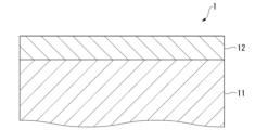
- FIG. 1 is a cross-sectional schematic diagram of a plated steel material according to an embodiment of the present invention.
- the sacrificial corrosion protection of the plating layer is achieved by forming a plating layer on the surface of the steel material that contains elements (e.g., Zn, Mg, etc.) that have a higher ionization tendency than the base steel, and allowing the plating layer to corrode preferentially over the base steel.
- elements e.g., Zn, Mg, etc.
- the inventors therefore conducted extensive research to improve the sacrificial corrosion resistance of the Zn plating layer containing Al and Mg.
- the ⁇ -Zn phase contained in the plating layer has a hexagonal crystal structure, which includes various crystal orientation planes.
- the corrosion resistance of these crystal orientation planes is not uniform across all orientation planes.
- the (002) plane of the ⁇ -Zn phase is a dense crystal orientation plane with a relatively high Zn atomic density, so Zn itself is relatively difficult to dissolve, and the corrosion resistance of Zn itself is considered to be relatively high.
- the (100) plane of the ⁇ -Zn phase is a crystal orientation plane with a lower Zn atomic density than the (002) plane, so Zn itself is relatively easy to dissolve, and although the corrosion resistance of Zn itself is low, the base steel is protected from corrosion by the corrosion products generated by the corrosion of Zn, so the sacrificial corrosion protection of the base steel is considered to be high. Therefore, it was thought that by orienting the (100) plane of the ⁇ -Zn phase parallel to the surface of the plating layer, it would be possible to improve the sacrificial corrosion protection properties of the Zn plating layer containing Al and Mg, specifically the red rust resistance and base steel corrosion protection properties.
- the present inventors have attempted to orient the (100) plane of the ⁇ -Zn phase contained in the coating layer parallel to the surface of the coating layer.
- the ⁇ phase first crystallizes, followed by the MgZn 2 phase and the ⁇ -Zn phase, and further a ternary eutectic structure containing the ⁇ phase, the MgZn 2 phase and the ⁇ -Zn phase is generated.
- the ternary eutectic structure containing the ⁇ -Zn phase is oriented in a random direction.
- the plated steel material of this embodiment comprises a steel material and a plating layer disposed on the surface of the steel material, and the chemical composition of the plating layer contains, in mass%, Al: 6.0-30.0%, Mg: 3.0-15.0%, Fe: 0.01-15.00%, Si: 0-2.0%, Ca: 0-2.00%, and a total of 0.005-0.500% of one or two of La and Ce, Sb: 0-0.50%, Pb: 0-0.50%, Cu: 0-1.00%, Sn: 0-1.00%, Ti: 0-1.00%, Cr: 0-1.00%, Nb: 0-1.00%, Zr: 0-1.00%, Ni: 0-1.00%.
- the surface of the steel material referred to here is the interface between the plated layer and the steel material.
- I(100) Zn is the diffraction intensity of the (100) plane of the ⁇ -Zn phase
- I(002) Zn is the diffraction intensity of the (002) plane of the ⁇ -Zn phase
- I(101) Zn is the diffraction intensity of the (101) plane of the ⁇ -Zn phase
- I(100) Zn is the diffraction intensity of the (100) plane of the ⁇ -Zn phase.
- the "%" of the content of each element in the chemical composition means “mass %".
- the content of an element in the chemical composition may be expressed as element concentration (e.g., Zn concentration, Mg concentration, etc.).
- Red rust resistance refers to the property of suppressing the occurrence of red rust on exposed steel (e.g., cut end surfaces of plated steel, cracked plating during processing, and exposed steel due to peeling of the plating).
- Base steel corrosion resistance refers to the property of suppressing the increase in corrosion depth when corrosion occurs on exposed steel.
- Plane corrosion resistance refers to the corrosion-resistant property of the plating layer (specifically, the Zn-Al-Mg alloy layer) itself.
- Platinum layer refers to the plating film produced by the so-called hot-dip galvanizing process.
- the plated steel material 1 has a steel material 11.
- the steel material 11 may also be a formed base steel material such as a steel pipe, civil engineering and construction material (fences, corrugated pipes, drainage ditch covers, sand prevention boards, bolts, wire mesh, guardrails, water cut-off walls, etc.), home appliance parts (casings for air conditioner outdoor units, etc.), and automobile parts (suspension parts, etc.).
- Forming is, for example, various plastic processing techniques such as pressing, roll forming, and bending.
- the steel material 11 can be various steel materials such as general steel, Al-killed steel, extra-low carbon steel, high carbon steel, various high tensile steels, some high alloy steels (steels containing strengthening elements such as Ni and Cr, etc.).
- the steel material 11 may also be a hot-rolled steel plate, hot-rolled steel strip, cold-rolled steel plate, cold-rolled steel strip, etc. described in JIS G 3302:2010.
- the manufacturing method of the steel plate hot rolling method, pickling method, cold rolling method, etc.
- the steel material 11 serving as the plating base sheet may be a pre-plated steel material in which the surface of the steel material 11 is pre-plated.
- An example of the pre-plated steel material is Ni pre-plated steel material having Ni plating on the steel material 11.
- the pre-plated steel material is obtained, for example, by electrolytic treatment or displacement plating.
- the electrolytic treatment is performed by immersing the base steel material in a sulfate bath or chloride bath containing metal ions of various pre-plating components and performing electrolytic treatment.
- the displacement plating is performed by immersing the base steel material in an aqueous solution containing metal ions of various pre-plating components and having the pH adjusted with sulfuric acid, thereby causing displacement precipitation of the metal.
- the plated steel material 1 according to this embodiment has a plated layer 12 on a steel material 11.
- the plated layer 12 of the plated steel material 1 according to this embodiment is mainly composed of a Zn-Al-Mg alloy layer due to the chemical composition described below.
- the plated layer 12 of the plated steel material 1 according to this embodiment may include an Fe-Al-based interface alloy layer between the steel material 11 and the Zn-Al-Mg alloy layer.
- the plated layer 12 may be a single-layer structure of a Zn-Al-Mg alloy layer, or may be a laminated structure including a Zn-Al-Mg alloy layer and an Fe-Al-based interface alloy layer.
- the Fe-Al-based interface alloy layer may contain Ni.
- the chemical composition of the plating layer according to this embodiment is composed of Zn and other alloying elements.
- the chemical composition of the plating layer is described in detail below. Note that elements with a lower limit of 0% concentration are not essential for solving the problems of the plated steel according to this embodiment, but are optional elements that are permitted to be included in the plating layer for the purpose of improving characteristics, etc.
- Al forms an ⁇ -phase solid solution with Zn, and contributes to improving the corrosion resistance of flat surfaces, sacrificial corrosion resistance, and workability. Therefore, the Al concentration is set to 6.0% or more. % or more, 12.0% or more, or 15.0% or more. On the other hand, if Al is excessive, the Mg concentration and Zn concentration are relatively decreased, and the red rust resistance and the base steel corrosion resistance are deteriorated. Therefore, the Al concentration is set to 30.0% or less. The Al concentration may be set to 28.0% or less, 25.0% or less, or 20.0% or less.
- Mg is an essential element for ensuring the corrosion resistance of flat parts, the resistance to red rust, and the corrosion resistance of the base steel. Therefore, the Mg concentration is set to 3.0% or more. On the other hand, if the Mg concentration is excessive, the workability, especially the powdering property, may deteriorate, and furthermore the corrosion resistance of the flat surface may deteriorate. Therefore, the Mg concentration is set to 15.0% or less. The Mg concentration may be 12.0% or less, 10.0% or less, or 8.0% or less.
- the plating layer may contain 0.01% or more of Fe. It has been confirmed that the performance of the plating layer is not adversely affected if the Fe concentration is 15.00% or less. %, 0.10% or more, 0.50% or more, or 1.00% or more.
- the Fe concentration may be 10.00% or less, 5.00% or less, 2.00% or less, or 1.00% or more. % or less. Since Fe may be mixed in from the steel material, the Fe concentration may be 0.05% or more.
- the Si concentration may be 0%.
- Si contributes to improving the corrosion resistance of the flat portion. Therefore, the Si concentration is set to 0.05% or more, 0.1% or more, 0.2% or more, or 0.
- the Si concentration may be 1.5% or more.
- the Si concentration is set to 2.0% or less. It may be 0.5% or less, 1.0% or less, or 0.5% or less.
- the Ca concentration may be 0%.
- Ca is an element that can adjust the amount of Mg elution that is optimal for imparting corrosion resistance to the flat surface. Therefore, the Ca concentration is 0.05% or more.
- the Ca concentration may be 0.10% or more, or 0.50% or more.
- the Ca concentration is set to 2.00% or less.
- the Ca concentration may be 1.00% or less, 0.50% or less, or 0.10% or less.
- ⁇ Total of one or two of La and Ce 0.005 to 0.500%>
- the inclusion of either or both of La and Ce in the plating layer contributes to the improvement of red rust resistance and base steel corrosion resistance. If the total of La and Ce is less than 0.005%, the red rust resistance and base steel corrosion resistance cannot be improved. Furthermore, if the total of La and Ce exceeds 0.500%, the flat surface corrosion resistance deteriorates. Therefore, the total of one or both of La and Ce is set to 0.005 to 0.500%.
- the total of La and Ce may be 0.008% or more, 0.010% or more, or 0.050% or more. Furthermore, the total of La and Ce may be 0.200% or less, or 0.100% or less.
- the plating layer according to this embodiment contains Sb: 0-0.50%, Pb: 0-0.50%, Cu: 0-1.00%, Sn: 0-1.00%, Ti: 0-1.00%, Cr: 0-1.00%, Nb: 0-1.00%, Zr: 0-1.00%, Ni: 0-1.000%, Mn: 0-1.00%, Mo: 0-1.00%, Ag: One or more elements selected from the group consisting of 0-1.00%, Li: 0-1.00%, B: 0-0.500%, Y: 0-0.50%, P: 0-0.50%, Sr: 0-0.50%, Co: 0-0.500%, Bi: 0-0.500%, In: 0-0.50%, V: 0-0.500%, and W: 0-0.50% may be contained. The total of these elements is 0-5.0%. If the total exceeds 5.0%, the flat corrosion resistance, red rust resistance, and base steel corrosion resistance may decrease. In addition, since these elements are optional, the total amount may be 0%.
- the concentrations of Sb and Pb may be 0%.
- Sb and Pb contribute to improving red rust resistance and base steel corrosion resistance. Therefore, the concentrations of Sb and Pb may be 0.05% or more, 0.10% or more, or 0.15% or more.
- concentrations of Sb and Pb are 0.50% or less.
- concentrations of Sb and Pb may be 0.40% or less, 0.30% or less, or 0.25% or less.
- ⁇ Cu, Ti, Cr, Nb, Zr, Mn, Mo, Ag and Li 0 to 1.00% each>
- the concentrations of Cu, Ti, Cr, Nb, Zr, Mn, Mo, Ag and Li may each be 0%.
- these contribute to improving red rust resistance and base steel corrosion resistance. Therefore, the concentrations of Cu, Ti, Cr, Nb, Zr, Mn, Mo, Ag and Li may each be 0.05% or more, 0.08% or more, or 0.10% or more.
- the concentrations of Cu, Ti, Cr, Nb, Zr, Mn, Mo, Ag and Li are excessive, the corrosion resistance of the flat surface portion deteriorates.
- the concentrations of Cu, Ti, Cr, Nb, Zr, Mn, Mo, Ag and Li are each 1.00% or less.
- the concentrations of Cu, Ti, Cr, Nb, Zr, Mn, Mo, Ag and Li may each be 0.80% or less, 0.70% or less, or 0.60% or less.
- Ni concentration may be 0%.
- these elements contribute to improving red rust resistance and base steel corrosion resistance. Therefore, the Ni concentration is set to 0.050% or more, 0.080% or more, or 0.100% or more. % or more.
- the Ni concentration is set to 1.000% or less. It may be 700% or less, or 0.600% or less.
- the Sn concentration may be 0%.
- Sn is an element that forms an intermetallic compound with Mg and improves the red rust resistance of the plating layer and the corrosion resistance of the base steel.
- the Sn concentration is set to 1.00% or less.
- the concentration may be 0.50% or less, 0.30% or less, or 0.20% or less.
- the concentration of B may be 0%.
- B contributes to improving red rust resistance and base steel corrosion resistance. Therefore, the concentration of B is set to 0.100% or more, 0.150% or more, or 0.
- the concentration of B is set to 0.500% or less.
- the concentration of B is set to 0.400% or less. It may be set to 0.300% or less.
- ⁇ Y, P and Sr 0 to 0.50% each>
- the concentrations of Y, P and Sr may each be 0%.
- Y, P and Sr contribute to improving red rust resistance and base steel corrosion resistance. Therefore, the concentrations of Y, P and Sr may each be 0.10% or more, 0.15% or more, or 0.20% or more.
- the concentrations of B, Y, P and Sr are each set to 0.50% or less.
- the concentrations of Y, P and Sr may each be set to 0.40% or less, 0.30% or less.
- the concentrations of Co, Bi, and V may be 0%.
- Co, Bi, and V contribute to improving red rust resistance and base steel corrosion resistance. Therefore, the concentrations of Co, Bi, and V may be 0.100% or more, 0.150% or more, or 0.200% or more.
- the concentrations of Co, Bi, and V are 0.500% or less.
- the concentrations of Co, Bi, and V may be 0.400% or less, or 0.300% or less.
- the respective concentrations of In and W may be 0%. Meanwhile, In and W contribute to improving red rust resistance and base steel corrosion resistance. Therefore, the respective concentrations of In and W may be 0.10% or more, 0.15% or more, or 0.20% or more. Meanwhile, if the concentrations of In and W are excessive, the corrosion resistance of the flat portion deteriorates. Therefore, the respective concentrations of In and W are set to 0.50% or less. The respective concentrations of In and W may be set to 0.40% or less, or 0.30% or less.
- Zn and impurities The remainder of the components of the plating layer according to this embodiment are Zn and impurities.
- Zn is an element that provides the plating layer with flat portion corrosion resistance, red rust resistance, and base steel corrosion resistance.
- impurities refer to those that are mixed in from the manufacturing environment, etc., and those that are acceptable within a range that does not adversely affect the properties of the plated steel according to this embodiment.
- trace amounts of components other than Fe may be mixed in as impurities into the plating layer due to mutual atomic diffusion between the base steel and the plating bath.
- the chemical composition of the plating layer is measured by the following method.
- the plated steel is cut to a size of 30 mm x 30 mm to obtain a measurement sample.
- an acid solution is obtained by peeling and dissolving the plating layer of the measurement sample using a 10% hydrochloric acid solution containing 0.06 mass% of an inhibitor (Ibit 710K, manufactured by Asahi Chemical Industry Co., Ltd.) that suppresses corrosion of steel.
- the obtained acid solution is then subjected to ICP analysis. This allows the chemical composition of the plating layer to be obtained. Note that when cutting the plated steel, it is preferable to avoid the ends and welds of the plated steel.
- the type of acid there are no particular restrictions on the type of acid as long as it is an acid that can dissolve the plating layer. For example, 10% by volume of HCl is used. Note that the chemical composition is measured three times using the above-mentioned method, and the average of the measurements is taken as the chemical composition of the plating layer.
- the plating layer contains an ⁇ phase and an MgZn 2 phase.
- the ⁇ phase is a phase containing a fine Al phase and a fine Zn phase.
- the ⁇ phase and the MgZn 2 phase may partially form a lamellar binary eutectic structure ( ⁇ phase/MgZn 2 eutectic structure).
- ⁇ phase/MgZn 2 eutectic structure When the ⁇ phase/MgZn 2 eutectic structure is included, the corrosion resistance of the flat surface of the plating layer is further improved.
- the ⁇ phase/MgZn 2 eutectic structure may be in the range of 70% or less, 5 to 70%, or 10 to 70% in terms of area ratio.
- the eutectic structure of [ ⁇ phase/MgZn2 ] may be 0% or more than 0%.
- the plating layer of the present embodiment contains an ⁇ -Zn phase in addition to the ⁇ -phase and the MgZn 2 -phase. At least a part of the ⁇ -Zn phase forms a ternary eutectic structure together with the ⁇ -phase and the MgZn 2 -phase.
- the ⁇ -Zn phase may be contained in the plating layer as a massive ⁇ -Zn phase.
- the plating layer when the plating layer contains 0.05 to 0.5% Sn, the plating layer definitely contains the Mg 2 Sn phase.
- the Mg 2 Sn phase may be contained even when the Sn content is 0.05% or less. Since the amount of the Mg 2 Sn phase is small, its presence can be confirmed by X-ray diffraction measurement. The presence of the Mg 2 Sn phase in the plating layer further improves the red rust resistance of the plated steel material.
- X-ray diffraction measurements are performed using K ⁇ radiation from a Cu tube, and if a peak is detected at 23.4 ⁇ 0.3°, it is determined that the Mg2Sn phase is present.
- X-ray diffraction measurements are performed using an X-ray diffraction device (Rigaku Corporation, model number RINT-TTR III) with an X-ray output of 50 kV, 300 mA, copper target, goniometer TTR (horizontal goniometer), K ⁇ filter slit width of 0.05 mm, longitudinal limiting slit width of 2 mm, receiving slit width of 8 mm, receiving slit 2 open, and measurement conditions of scan speed 5 deg./min, step width 0.01 deg, and scan axis 2 ⁇ (5 to 90°).
- the plating layer may contain one or more of a LaCe-containing intermetallic compound phase, a La-containing intermetallic compound phase, and a Ce-containing intermetallic compound phase, as described below.
- the plating layer may contain other phases as the remainder, other than those mentioned above.
- it may contain an Al-Ca-Si phase.
- the crystal orientation of the ⁇ -Zn phase will be described.
- the X-ray diffraction intensity obtained from the X-ray diffraction measurement of the plating layer needs to satisfy the relationship of the following formula (1).
- the (100) plane of the ⁇ -Zn phase is oriented so as to be parallel to the surface of the plating layer, and both the red rust resistance and the base steel corrosion resistance are improved. It is more preferable to satisfy the following formula (2).
- I(100) Zn is the diffraction intensity of the (100) plane of the ⁇ -Zn phase
- I(002) Zn is the diffraction intensity of the (002) plane of the ⁇ -Zn phase
- I(101) Zn is the diffraction intensity of the (101) plane of the ⁇ -Zn phase
- I(100) Zn is the diffraction intensity of the (100) plane of the ⁇ -Zn phase.
- the surface structure of the plating layer contains a total of one or more of the following intermetallic compound phases: LaCe-containing intermetallic compound phase, La-containing intermetallic compound phase, and Ce-containing intermetallic compound phase in a 200 ⁇ m x 200 ⁇ m field of view when viewed in plan. More preferably, three or more of these intermetallic compound phases are contained in a 200 ⁇ m x 200 ⁇ m field of view. It is preferable that 10 or less of one or more of the intermetallic compound phases are contained in a 200 ⁇ m x 200 ⁇ m field of view.
- the LaCe-containing intermetallic compound phase is an intermetallic compound phase containing La and Ce
- the La-containing intermetallic compound phase is an intermetallic compound phase containing La
- the Ce-containing intermetallic compound phase is an intermetallic compound phase containing Ce.
- Elements other than La and Ce contained in these intermetallic compound phases include Al, Ca, Si, Mg, and Zn.
- these intermetallic compound phases may contain Al-Ca-Si-Mg-Zn-(La,Ce) phase, Ca-Zn-(La,Ce) phase, etc.
- the notation (La,Ce) means either or both of La and Ce.
- the method for measuring the area ratio of the [ ⁇ -phase/ MgZn2 eutectic structure] is as follows. First, the surface of the plating layer is adjusted to be flat by mechanical polishing. Next, the surface of the plating layer is chemically polished by colloidal polishing until the surface becomes a mirror surface. The surface of the plated layer after polishing is observed with an SEM. Specifically, an element distribution image is taken using an SEM-EDS at a magnification of 5000 times (area of 200 ⁇ m long and 200 ⁇ m wide). In this element distribution image, the phase in which Mg and Zn coexist is identified as the MgZn 2 phase. Also, the phase containing Al and Zn is identified as the ⁇ phase.
- the area ratio of the [ ⁇ phase/MgZn 2 eutectic structure] contained in the field of view is calculated by binarization using image analysis software.
- the method for measuring I(100) Zn / ⁇ I(002) Zn +I(101) Zn +I(100) Zn ⁇ in formulas (1) and (2) is as follows. First, the surface of the plating layer is mechanically polished, and if necessary, chemically polished to make the surface of the plating layer mirror-finished.
- an X-ray diffraction apparatus manufactured by Rigaku Corporation (model number RINT-TTR) III
- copper target copper target
- goniometer TTR horizontal goniometer
- longitudinal limiting slit width 2 mm longitudinal limiting slit width 2 mm
- receiving slit width 8 mm receiving slit 2 open
- measurement conditions of scan speed 5 deg. /min, step width 0.01 deg, scan axis 2 ⁇ (5 to 90°) are used to perform X-ray diffraction measurement.
- the diffraction intensity of the (100) plane of the ⁇ -Zn phase (maximum intensity in the range of 38.993 ⁇ 0.2°)
- the diffraction intensity of the (002) plane (maximum intensity in the range of 36.297 ⁇ 0.2°)
- the diffraction intensity of the (101) plane (maximum intensity in the range of 43.232 ⁇ 0.2°) are measured.
- the diffraction intensity is the intensity excluding the background intensity. From the obtained diffraction intensity, I(100) Zn / ⁇ I(002) Zn +I(101) Zn +I(100) Zn ⁇ is calculated.
- Whether or not the plating layer contains an Mg 2 Sn phase is determined by whether or not a diffraction peak specific to Mg 2 Sn appears when the above-mentioned X-ray diffraction measurement is performed.
- the method for measuring the number of LaCe-containing intermetallic compound phases, La-containing intermetallic compound phases, and Ce-containing intermetallic compound phases in the surface structure of the plating layer is as follows. First, the surface of the plating layer is mechanically polished, and if necessary, chemically polished to make the surface of the plating layer in a mirror state. Next, a rectangular observation field of 200 ⁇ m in length and 200 ⁇ m in width is set on the surface of the plating layer. An element distribution image is taken of this observation field using SEM-EDS. In this element distribution image, phases containing either La or Ce or both are identified as one of the LaCe-containing intermetallic compound phases, La-containing intermetallic compound phases, and Ce-containing intermetallic compound phases. Then, the number of these intermetallic compounds is counted.
- the coating weight per side of the plating layer may be, for example, within the range of 20 to 300 g/ m2 .
- the coating weight per side 20 g/m2 or more the flat corrosion resistance, red rust resistance, and base steel corrosion resistance of the plated steel can be further improved.
- the coating weight per side 300 g/m2 or less the workability of the plated steel can be further improved.
- the method for producing the plated steel material of this embodiment is not particularly limited.
- the plated steel material of this embodiment can be obtained according to the production conditions described below.
- a steel material having an uneven surface is used as an original sheet for plating.
- This steel material is annealed in a reducing atmosphere, and the steel material immediately after annealing is immersed in a hot-dip plating bath and then pulled out to form a plating layer on the surface of the steel material.
- the plating layer is cooled at an average cooling rate of 15°C/sec or more until the temperature of the plating layer reaches 340°C from the bath temperature, and then cooled at an average cooling rate of 7°C/sec or less in the range of 340 to 320°C while spraying a cooling gas at a flux of 15,000 (L/min/m 2 ) or more.
- the roughness of the surface of the steel material to be plated is such that the ratio ( Lp/L0) of the curve length Lp of the roughness curve per the reference length L0 is 1.08 or more.
- the upper limit of ( Lp / L0 ) is preferably 3.00 or less, and may be 2.50 or less.
- the reference length L0 is the length of the plating layer in the longitudinal direction when the plating layer is viewed in cross section
- the curve length Lp is the curve length of the roughness curve relative to the reference length L0 when the plating layer is viewed in cross section, i.e., the total length of the contour line of the surface of the plating layer.
- the roughness of the steel surface can be adjusted, for example, by rolling the plated base sheet with a rolling roll or a roll for temper rolling whose roll surface has been adjusted to the desired roughness, thereby transferring the surface shape of the roll. It can also be adjusted by pickling.
- the measurement of (L p /L 0 ) is performed, for example, using a shape measuring laser microscope (model number: VK-8700) manufactured by Keyence Corporation.
- the measurement conditions are, for example, scan area: 200 ⁇ m ⁇ 200 ⁇ m, measurement mode: laser confocal, measurement quality: high precision, pitch: 0.75 ⁇ m, double scan: ON, optical zoom: 1x, objective lens name: Plan, ⁇ coefficient: 0.45, offset: 0%.
- the measurement device used to measure (L p /L 0 ) is not limited to the above example.
- Annealing of the steel material to be plated is carried out in a reducing atmosphere. There are no particular restrictions on the reducing atmosphere and annealing conditions. This annealing removes as much oxide as possible from the steel surface.
- the chemical composition of the hot-dip galvanizing bath may be adjusted appropriately so as to obtain the chemical composition of the plating layer described above.
- the temperature of the hot-dip galvanizing bath is not particularly limited, and any temperature at which hot-dip galvanizing can be performed may be appropriately selected.
- the temperature of the galvanizing bath may be set to a value approximately 20°C higher than the melting point of the galvanizing bath.
- the amount of the plating layer attached can be controlled by controlling the pulling speed of the steel material. If necessary, the steel material to which the plating layer is attached may be wiped to control the amount of the plating layer attached.
- the amount of the plating layer attached is not particularly limited, and can be within the above-mentioned range, for example.
- the plating layer is cooled.
- the plating layer is cooled at an average cooling rate of 15°C/sec or more until the temperature of the plating layer is reduced from the bath temperature to 340°C.
- the average cooling rate from the bath temperature to 340°C may be 30°C/sec or less.
- the cooling can be performed, for example, by spraying cooling gas.
- spraying cooling gas multiple spray nozzles for cooling gas are arranged along the steel material transport path, and the cooling gas is sprayed from the nozzles.
- the ⁇ -phase dendrites can become nucleation sites during the crystallization of the ternary eutectic structure, and by suppressing the generation of the ⁇ -phase, the ternary eutectic structure is formed from the nucleation sites near the interface between the steel material and the plating layer.
- cooling is performed in the range of 340 to 320°C at an average cooling rate of 7°C/sec or less while blowing cooling gas at a flux of 15000 (L/min/m 2 ) or more.
- cooling may be performed at an average cooling rate of 2°C or more.
- the flux of the cooling gas during cooling may be 25000 (L/min/m 2 ) or less.
- multiple blowing nozzles for cooling gas are arranged along the transport path of the steel material. Then, by setting the flux to 15000 (L/min/m 2 ) or more, vibration is applied to the plating layer by blowing the cooling gas without excessive supercooling. As a result, crystallization of the ternary eutectic structure starts from the vicinity of the interface between the plating layer and the steel material, and the ternary eutectic structure grows toward the surface of the plating layer.
- cooling gas to be sprayed there are no particular limitations on the cooling gas to be sprayed, and it may be a non-oxidizing gas such as nitrogen, an inert gas such as argon, or air, or a mixture of these.
- a non-oxidizing gas such as nitrogen, an inert gas such as argon, or air, or a mixture of these.
- the shape of the gas nozzle from which the cooling gas is ejected is, for example, in the range of 1 to 50 mm in diameter.
- the angle between the tip of the gas nozzle and the steel plate is, for example, in the range of 70 to 110°, and more preferably 90° (right angle).
- the distance between the tip of the gas nozzle and the steel plate is in the range of 30 to 1000 mm. Note that the shape, angle, and distance of the gas nozzle are merely examples and are not limited to the above ranges.
- a nucleation site of the ternary eutectic structure is formed near the interface between the steel material and the plating layer. Then, by cooling the steel material immersed in the plating bath under the above conditions when it is pulled up, the nucleation site from which the crystallization of the ternary eutectic structure starts is directed to be near the interface between the steel material and the plating layer, rather than the ⁇ -phase dendrites.
- the ternary eutectic structure crystallized from near the interface between the steel material and the plating layer has a crystal orientation oriented in a fixed direction, unlike when the crystallization starts from the ⁇ -phase dendrites. As a result, it is believed that the (100) plane of the ⁇ -Zn phase contained in the ternary eutectic structure is oriented parallel to the surface of the plating layer, satisfying the above formula (1).
- the conditions in the embodiment are merely one example of conditions adopted to confirm the feasibility and effects of the present invention.
- the present invention is not limited to this one example of conditions.
- Various conditions may be adopted in the present invention as long as they do not deviate from the gist of the present invention and the object of the present invention is achieved.
- a hot-rolled steel sheet having a thickness of 1.6 mm was used as the base sheet for plating.
- the surface roughness of the hot-rolled steel sheet was controlled in advance using a skin pass mill or the like. The surface roughness was adjusted so that the ratio of the curve length Lp of the roughness curve per reference length L0 ( Lp / L0 ) was 1.05 to 1.57.
- the (L p /L 0 ) was measured using a shape measuring laser microscope (model number: VK-8700) manufactured by Keyence Corporation. The measurement was performed under the following measurement conditions: measurement mode: laser confocal, measurement quality: high precision, pitch: 0.75 ⁇ m, double scan: ON, optical zoom: 1x, objective lens name: Plan, ⁇ coefficient: 0.45, offset: 0%.
- the plated original sheet with the adjusted surface roughness was annealed.
- the annealing conditions were N 2 -4% H 2 atmosphere, soaking temperature 800 ° C, soaking time 2 minutes.
- the plated original sheet after annealing was air-cooled with N 2 gas to adjust the temperature at the time of immersion in the plating bath to about (plating bath temperature + 20) ° C, and then immersed in various hot-dip plating baths and pulled up at a pulling speed of 20 to 200 mm / sec. During pulling, the plating adhesion amount was controlled by N 2 wiping gas. After the steel material was pulled out of the plating bath, cooling was performed under the conditions shown in Table 2.
- N2 gas was used as the cooling gas, and the gas flux was controlled as shown in Table 2.
- the shape of the gas nozzle from which the cooling gas was ejected was 6 mm in diameter, the angle between the tip of the gas nozzle and the steel plate was a right angle, and the distance between the tip of the gas nozzle and the steel plate was 35 mm. In this manner, plated steel products No. 1 to No. 47 were produced.
- the chemical composition of the plating layer is as shown in Table 1.
- the metal structure of the plating layer was also evaluated, and the results are shown in Table 3.
- the red rust resistance and base steel corrosion resistance of the plated steel were evaluated, and the results are shown in Table 4.
- the chemical composition of the plating layer was measured by immersing samples cut to a size of 30 mm x 30 mm in a 10% HCl aqueous solution containing an inhibitor to remove the plating layer by pickling, and then performing ICP analysis of the elements dissolved in the aqueous solution.
- the area ratio of the [ ⁇ -phase/MgZn 2 eutectic structure] was evaluated as follows. First, the surface of the plating layer was polished to a mirror state by mechanical polishing and colloidal polishing. Next, the plating layer surface was observed at a magnification of 5000 times (200 ⁇ m long, 200 ⁇ m long area) using a field emission scanning electron microscope (FE-SEM) equipped with an energy dispersive elemental analyzer (EDS), and an element distribution image was taken using the EDS.
- FE-SEM field emission scanning electron microscope
- EDS energy dispersive elemental analyzer
- the phase in which Mg and Zn coexist was identified as the MgZn 2 phase, and the phase containing Al and Zn was identified as the ⁇ phase, and the [ ⁇ -phase/MgZn 2 eutectic structure] in which these are in a lamellar shape was identified. Then, the area ratio of the [ ⁇ -phase/MgZn 2 eutectic structure] contained in the field of view was calculated by binarization using image analysis software.
- the measurement method of I(100) Zn / ⁇ I(002) Zn +I(101) Zn +I(100) Zn ⁇ in formula (1) was as follows. First, the surface of the plating layer was mirror-finished in the same manner as above. Next, an X-ray diffraction measurement was performed using an X-ray diffractometer (Rigaku Corporation, model number RINT-TTR III) with an X-ray output of 50 kV, 300 mA, copper target, goniometer TTR (horizontal goniometer), K ⁇ filter slit width of 0.05 mm, longitudinal limiting slit width of 2 mm, receiving slit width of 8 mm, and receiving slit 2 open, with a scan speed of 5 deg./min, a step width of 0.01 deg, and a scan axis 2 ⁇ (5 to 90°).
- X-ray diffractometer Raku Corporation, model number RINT-TTR III
- K ⁇ filter slit width of 0.05 mm longitudinal
- the diffraction intensity of the (100) plane of the ⁇ -Zn phase (maximum intensity in the range of 38.993 ⁇ 0.2°)
- the diffraction intensity of the (002) plane maximum intensity in the range of 36.297 ⁇ 0.2°
- the diffraction intensity of the (101) plane maximum intensity in the range of 43.232 ⁇ 0.2°
- the diffraction intensity was the intensity excluding the background intensity. From the obtained diffraction intensities, I(100) Zn / ⁇ I(002) Zn +I(101) Zn +I(100) Zn ⁇ was calculated.
- the plating layer contained an Mg 2 Sn phase was judged based on whether or not a diffraction peak specific to Mg 2 Sn appeared when the above-mentioned X-ray diffraction measurement was performed.
- the number of LaCe-containing intermetallic compound phases, La-containing intermetallic compound phases, and Ce-containing intermetallic compound phases in the surface structure of the plating layer was measured.
- the surface of the plating layer was made into a mirror state in the same manner as above.
- a rectangular observation field of 200 ⁇ m in length and 200 ⁇ m in width was set on the surface of the plating layer.
- An element distribution image was taken of this observation field using SEM-EDS.
- phases containing either La or Ce or both were identified as any one of the LaCe-containing intermetallic compound phases, La-containing intermetallic compound phases, and Ce-containing intermetallic compound phases.
- the number of these intermetallic compounds was counted.
- the results are shown in Table 3.
- the column "LaCe-containing intermetallic compound phase" in Table 3 shows the total number of LaCe-containing intermetallic compound phases, La-containing intermetallic compound phases, and Ce-containing intermetallic compound phases.
- Red rust resistance was evaluated as follows. Plated steel was cut into 100 mm x 100 mm test pieces. The plating layer in a 30 mm diameter area centred on the intersection of the diagonals of the test piece was removed by milling to expose the steel sheet (base steel). A combined cycle test as stipulated in the JASO-M609-91 method was carried out on the exposed 30 mm diameter area of the base steel, and evaluation was based on the occurrence of red rust in the exposed area of the base steel. The evaluation criteria for red rust resistance are as follows. "AAAA”, “AAA”, “AA” and "A” were deemed to be acceptable.
- AAAA Red rust area ratio of 2% or less at 120 cycles
- AAA Red rust area ratio of 2% to 5% at 120 cycles
- AA Red rust area ratio of 5% to 10% at 120 cycles
- the corrosion resistance of the steel substrate was evaluated as follows.
- the plated steel was cut into 100 mm x 100 mm test pieces.
- the plating layer in a 25 mm diameter area centred on the intersection of the diagonals of the test piece was removed by milling to expose the steel sheet (steel substrate).
- a combined cycle test as stipulated in the JASO-M609-91 method was carried out on the 25 mm diameter exposed steel substrate area, and evaluation was based on the maximum steel substrate corrosion depth in the exposed steel substrate area.
- the evaluation criteria for steel substrate corrosion resistance are as follows. "AAA”, "AA" and "A" were deemed to be acceptable.
- AAA 0.5 mm or less at 360 cycles AA: 0.5 mm or less at 240 cycles A: 0.5 mm or less at 180 cycles B: Over 0.5 mm at 180 cycles
- Nos. 1 to 32 and 42 to 47 (Examples) according to the present invention had appropriately controlled chemical compositions and metal structures of the plating layer, and were excellent in both red rust resistance and base steel corrosion resistance.
- Comparative example No. 33 had an insufficient amount of Al in the plating layer. As a result, No. 31 had insufficient corrosion protection for the base steel.
- Comparative example No. 34 had an excessive amount of Al in the plating layer.
- No. 32 excessive ⁇ -phase dendrites were formed, and these dendrites functioned as nucleation sites for the ⁇ -Zn phase, making it impossible to ensure the orientation of the ⁇ -Zn phase, resulting in a lack of both red rust resistance and base steel corrosion resistance.
- Comparative example No. 35 had an insufficient amount of Mg in the plating layer. As a result, No. 33 lacked both red rust resistance and base steel corrosion resistance.
- Comparative example No. 36 had an insufficient total amount of La and Ce in the plating layer. As a result, the orientation of the ⁇ -Zn phase could not be ensured in No. 36, and the base steel corrosion resistance was insufficient.
- the plated steel material disclosed herein has excellent red rust resistance and base steel corrosion resistance, making it highly applicable in industry.
Landscapes
- Chemical & Material Sciences (AREA)
- Organic Chemistry (AREA)
- Engineering & Computer Science (AREA)
- Materials Engineering (AREA)
- Mechanical Engineering (AREA)
- Metallurgy (AREA)
- Chemical Kinetics & Catalysis (AREA)
- Physics & Mathematics (AREA)
- Oil, Petroleum & Natural Gas (AREA)
- Thermal Sciences (AREA)
- Coating With Molten Metal (AREA)
- Analysing Materials By The Use Of Radiation (AREA)
- Other Surface Treatments For Metallic Materials (AREA)
- Electroplating And Plating Baths Therefor (AREA)
Priority Applications (4)
| Application Number | Priority Date | Filing Date | Title |
|---|---|---|---|
| CN202480024726.0A CN120917176A (zh) | 2023-04-11 | 2024-04-11 | 镀覆钢材 |
| EP24788800.1A EP4696805A4 (en) | 2023-04-11 | 2024-04-11 | PLATED STEEL MATERIAL |
| JP2024545086A JP7606152B1 (ja) | 2023-04-11 | 2024-04-11 | めっき鋼材 |
| AU2024250020A AU2024250020A1 (en) | 2023-04-11 | 2024-04-11 | Plated steel material |
Applications Claiming Priority (2)
| Application Number | Priority Date | Filing Date | Title |
|---|---|---|---|
| JP2023-064063 | 2023-04-11 | ||
| JP2023064063 | 2023-04-11 |
Publications (1)
| Publication Number | Publication Date |
|---|---|
| WO2024214778A1 true WO2024214778A1 (ja) | 2024-10-17 |
Family
ID=93059376
Family Applications (1)
| Application Number | Title | Priority Date | Filing Date |
|---|---|---|---|
| PCT/JP2024/014675 Ceased WO2024214778A1 (ja) | 2023-04-11 | 2024-04-11 | めっき鋼材 |
Country Status (6)
| Country | Link |
|---|---|
| EP (1) | EP4696805A4 (https=) |
| JP (1) | JP7606152B1 (https=) |
| CN (1) | CN120917176A (https=) |
| AU (1) | AU2024250020A1 (https=) |
| TW (1) | TWI902216B (https=) |
| WO (1) | WO2024214778A1 (https=) |
Citations (6)
| Publication number | Priority date | Publication date | Assignee | Title |
|---|---|---|---|---|
| JPS5521564A (en) * | 1978-08-04 | 1980-02-15 | Kawasaki Steel Corp | Preparation of melted zinc plated steel plate for sheath plate |
| JP2001355053A (ja) * | 2000-04-11 | 2001-12-25 | Nippon Steel Corp | 表面性状に優れた溶融Zn−Al−Mg−Siめっき鋼材とその製造方法 |
| WO2005056863A1 (ja) * | 2003-12-12 | 2005-06-23 | Sumitomo Metal Industries, Ltd. | 溶融亜鉛めっき鋼板及びその製造方法 |
| WO2011001662A1 (ja) | 2009-06-30 | 2011-01-06 | 新日本製鐵株式会社 | Zn-Al-Mg系溶融めっき鋼板とその製造方法 |
| JP2021085086A (ja) | 2019-11-29 | 2021-06-03 | 日本製鉄株式会社 | 溶融めっき鋼板 |
| JP2023064063A (ja) | 2021-10-25 | 2023-05-10 | 株式会社Opt Fit | 情報処理方法、プログラム及び情報処理装置 |
Family Cites Families (7)
| Publication number | Priority date | Publication date | Assignee | Title |
|---|---|---|---|---|
| US6607844B1 (en) * | 1999-03-15 | 2003-08-19 | Kobe Steel, Ltd. | Zn-Mg electroplated metal sheet and fabrication process therefor |
| CN101336308B (zh) * | 2006-01-30 | 2012-08-29 | 新日本制铁株式会社 | 成形性及镀覆性优良的高强度热浸镀锌钢板和高强度合金化热浸镀锌钢板及其制造方法和制造装置 |
| US20110256420A1 (en) * | 2008-07-30 | 2011-10-20 | Pangang Group Steel Vanadium & Titanium Co., Ltd. | Hot-dip galvanized steel plate and production method thereof |
| JP6687175B1 (ja) * | 2018-05-16 | 2020-04-22 | 日本製鉄株式会社 | めっき鋼材 |
| KR102413245B1 (ko) * | 2020-09-15 | 2022-06-27 | 주식회사 포스코 | 염화물 환경에서 내부식성이 우수한 용융아연 도금강판 및 이의 제조방법 |
| KR102738107B1 (ko) * | 2020-10-20 | 2024-12-05 | 닛폰세이테츠 가부시키가이샤 | 도금 강판 |
| HUE069505T2 (hu) * | 2021-09-07 | 2025-03-28 | Nippon Steel Corp | Forrón merített galvanizált acél anyag |
-
2024
- 2024-04-11 CN CN202480024726.0A patent/CN120917176A/zh active Pending
- 2024-04-11 TW TW113113593A patent/TWI902216B/zh active
- 2024-04-11 AU AU2024250020A patent/AU2024250020A1/en active Pending
- 2024-04-11 JP JP2024545086A patent/JP7606152B1/ja active Active
- 2024-04-11 WO PCT/JP2024/014675 patent/WO2024214778A1/ja not_active Ceased
- 2024-04-11 EP EP24788800.1A patent/EP4696805A4/en active Pending
Patent Citations (6)
| Publication number | Priority date | Publication date | Assignee | Title |
|---|---|---|---|---|
| JPS5521564A (en) * | 1978-08-04 | 1980-02-15 | Kawasaki Steel Corp | Preparation of melted zinc plated steel plate for sheath plate |
| JP2001355053A (ja) * | 2000-04-11 | 2001-12-25 | Nippon Steel Corp | 表面性状に優れた溶融Zn−Al−Mg−Siめっき鋼材とその製造方法 |
| WO2005056863A1 (ja) * | 2003-12-12 | 2005-06-23 | Sumitomo Metal Industries, Ltd. | 溶融亜鉛めっき鋼板及びその製造方法 |
| WO2011001662A1 (ja) | 2009-06-30 | 2011-01-06 | 新日本製鐵株式会社 | Zn-Al-Mg系溶融めっき鋼板とその製造方法 |
| JP2021085086A (ja) | 2019-11-29 | 2021-06-03 | 日本製鉄株式会社 | 溶融めっき鋼板 |
| JP2023064063A (ja) | 2021-10-25 | 2023-05-10 | 株式会社Opt Fit | 情報処理方法、プログラム及び情報処理装置 |
Non-Patent Citations (1)
| Title |
|---|
| See also references of EP4696805A1 |
Also Published As
| Publication number | Publication date |
|---|---|
| CN120917176A (zh) | 2025-11-07 |
| TW202444938A (zh) | 2024-11-16 |
| JP7606152B1 (ja) | 2024-12-25 |
| EP4696805A1 (en) | 2026-02-18 |
| JPWO2024214778A1 (https=) | 2024-10-17 |
| TWI902216B (zh) | 2025-10-21 |
| EP4696805A4 (en) | 2026-04-08 |
| AU2024250020A1 (en) | 2025-10-02 |
Similar Documents
| Publication | Publication Date | Title |
|---|---|---|
| JP7698235B2 (ja) | めっき鋼板 | |
| TWI847757B (zh) | 鍍敷鋼板 | |
| US20260071301A1 (en) | Hot-dip plated steel material | |
| TWI794874B (zh) | 鍍敷鋼材 | |
| JP7606152B1 (ja) | めっき鋼材 | |
| JP7436945B1 (ja) | 溶融めっき鋼材 | |
| JP7606153B1 (ja) | めっき鋼材 | |
| JP7460943B1 (ja) | めっき鋼板 | |
| JP7436948B1 (ja) | めっき鋼板 | |
| TWI909413B (zh) | 鍍敷鋼材 | |
| JP7633587B1 (ja) | めっき鋼材および太陽光発電用架台 | |
| WO2025224818A1 (ja) | めっき鋼材 |
Legal Events
| Date | Code | Title | Description |
|---|---|---|---|
| WWE | Wipo information: entry into national phase |
Ref document number: 2024545086 Country of ref document: JP |
|
| 121 | Ep: the epo has been informed by wipo that ep was designated in this application |
Ref document number: 24788800 Country of ref document: EP Kind code of ref document: A1 |
|
| WWE | Wipo information: entry into national phase |
Ref document number: AU2024250020 Country of ref document: AU |
|
| WWE | Wipo information: entry into national phase |
Ref document number: 202517091357 Country of ref document: IN |
|
| ENP | Entry into the national phase |
Ref document number: 2024250020 Country of ref document: AU Date of ref document: 20240411 Kind code of ref document: A |
|
| WWE | Wipo information: entry into national phase |
Ref document number: 2501006906 Country of ref document: TH |
|
| WWE | Wipo information: entry into national phase |
Ref document number: 202480024726.0 Country of ref document: CN |
|
| REG | Reference to national code |
Ref country code: BR Ref legal event code: B01A Ref document number: 112025021121 Country of ref document: BR |
|
| WWP | Wipo information: published in national office |
Ref document number: 202517091357 Country of ref document: IN |
|
| WWP | Wipo information: published in national office |
Ref document number: 202480024726.0 Country of ref document: CN |
|
| WWE | Wipo information: entry into national phase |
Ref document number: 2024788800 Country of ref document: EP |
|
| NENP | Non-entry into the national phase |
Ref country code: DE |
|
| ENP | Entry into the national phase |
Ref document number: 2024788800 Country of ref document: EP Effective date: 20251111 |
|
| ENP | Entry into the national phase |
Ref document number: 2024788800 Country of ref document: EP Effective date: 20251111 |
|
| WWE | Wipo information: entry into national phase |
Ref document number: 11202506456R Country of ref document: SG |
|
| WWP | Wipo information: published in national office |
Ref document number: 11202506456R Country of ref document: SG |
|
| ENP | Entry into the national phase |
Ref document number: 2024788800 Country of ref document: EP Effective date: 20251111 |
|
| ENP | Entry into the national phase |
Ref document number: 2024788800 Country of ref document: EP Effective date: 20251111 |
|
| ENP | Entry into the national phase |
Ref document number: 2024788800 Country of ref document: EP Effective date: 20251111 |
|
| ENP | Entry into the national phase |
Ref document number: 2024788800 Country of ref document: EP Effective date: 20251111 |
|
| ENP | Entry into the national phase |
Ref document number: 2024788800 Country of ref document: EP Effective date: 20251111 |
|
| ENP | Entry into the national phase |
Ref document number: 2024788800 Country of ref document: EP Effective date: 20251111 |
|
| ENP | Entry into the national phase |
Ref document number: 2024788800 Country of ref document: EP Effective date: 20251111 |
|
| WWP | Wipo information: published in national office |
Ref document number: 2024788800 Country of ref document: EP |