WO2024214765A1 - 金型、及び熱間プレス成形品の製造方法 - Google Patents
金型、及び熱間プレス成形品の製造方法 Download PDFInfo
- Publication number
- WO2024214765A1 WO2024214765A1 PCT/JP2024/014643 JP2024014643W WO2024214765A1 WO 2024214765 A1 WO2024214765 A1 WO 2024214765A1 JP 2024014643 W JP2024014643 W JP 2024014643W WO 2024214765 A1 WO2024214765 A1 WO 2024214765A1
- Authority
- WO
- WIPO (PCT)
- Prior art keywords
- hot press
- region
- blank
- mold
- slow cooling
- Prior art date
- Legal status (The legal status is an assumption and is not a legal conclusion. Google has not performed a legal analysis and makes no representation as to the accuracy of the status listed.)
- Ceased
Links
Images






Classifications
-
- B—PERFORMING OPERATIONS; TRANSPORTING
- B21—MECHANICAL METAL-WORKING WITHOUT ESSENTIALLY REMOVING MATERIAL; PUNCHING METAL
- B21D—WORKING OR PROCESSING OF SHEET METAL OR METAL TUBES, RODS OR PROFILES WITHOUT ESSENTIALLY REMOVING MATERIAL; PUNCHING METAL
- B21D22/00—Shaping without cutting, by stamping, spinning, or deep-drawing
- B21D22/20—Deep-drawing
-
- B—PERFORMING OPERATIONS; TRANSPORTING
- B21—MECHANICAL METAL-WORKING WITHOUT ESSENTIALLY REMOVING MATERIAL; PUNCHING METAL
- B21D—WORKING OR PROCESSING OF SHEET METAL OR METAL TUBES, RODS OR PROFILES WITHOUT ESSENTIALLY REMOVING MATERIAL; PUNCHING METAL
- B21D24/00—Special deep-drawing arrangements in, or in connection with, presses
-
- B—PERFORMING OPERATIONS; TRANSPORTING
- B21—MECHANICAL METAL-WORKING WITHOUT ESSENTIALLY REMOVING MATERIAL; PUNCHING METAL
- B21D—WORKING OR PROCESSING OF SHEET METAL OR METAL TUBES, RODS OR PROFILES WITHOUT ESSENTIALLY REMOVING MATERIAL; PUNCHING METAL
- B21D37/00—Tools as parts of machines covered by this subclass
- B21D37/16—Heating or cooling
-
- C—CHEMISTRY; METALLURGY
- C21—METALLURGY OF IRON
- C21D—MODIFYING THE PHYSICAL STRUCTURE OF FERROUS METALS; GENERAL DEVICES FOR HEAT TREATMENT OF FERROUS OR NON-FERROUS METALS OR ALLOYS; MAKING METAL MALLEABLE, e.g. BY DECARBURISATION OR TEMPERING
- C21D1/00—General methods or devices for heat treatment, e.g. annealing, hardening, quenching or tempering
- C21D1/62—Quenching devices
- C21D1/673—Quenching devices for die quenching
Definitions
- This disclosure relates to dies, and more specifically, to dies for hot press molding.
- hot press forming a blank (steel sheet) is heated to a temperature range where the microstructure becomes austenite single phase.
- the heated blank is then hot press-formed using a hot press device equipped with a die.
- the blank is softened by heating. This makes it easier to press-form the blank into a desired shape.
- the blank during hot press forming comes into contact with substantially the entire forming surface of the die. At this time, the blank is heat-removed and quenched by the die in contact with the blank.
- the blank is formed and quenched at the same time, so that a hot press formed product having high strength can be easily manufactured by the hot press forming.
- Hot press-formed products used as structural components of automobiles are required to have high strength, but sometimes low strength is required in some areas.
- the strength of the lower part of the B-pillar is required to be low to increase impact absorption capacity.
- the remaining parts other than the lower part are required to have high strength (high rigidity).
- Patent Document 1 JP Patent Publication 2014-79790.
- a heated material is hot press molded using a die.
- a refrigerant is flowed into a part of the gap between the die and the material to partially quench the material.
- the die of Patent Document 1 has a supply port on the die surface that supplies the refrigerant in the refrigerant path inside the die to the outside of the die.
- the die of Patent Document 1 further has a convex portion that contacts the boundary region between the high strength portion and the low strength portion of the material.
- the refrigerant is supplied from the supply port to the gap between the high strength portion and the die.
- the refrigerant is not supplied to the gap between the low strength portion and the die.
- the convex portion that contacts the boundary between the high strength portion and the low strength portion blocks the refrigerant. Therefore, the refrigerant filled in the gap between the high strength part and the die does not flow into the gap between the low strength part and the die. As a result, a hot press molded product having a high strength part and a low strength part is produced.
- Patent Document 1 can produce hot press molded products having areas with high strength and areas with low strength.
- hot press molded products having high strength and low strength areas may also be produced by other techniques different from the technique described in Patent Document 1.
- the objective of this disclosure is to provide a mold capable of producing a hot press molded product having areas with high strength and areas with low strength by hot press molding.
- the second quenching region is disposed opposite the first quenching region across the blank during hot press forming, and contacts the blank to cool the blank.
- the second slow cooling region is disposed opposite the first slow cooling region across the blank during hot press forming, and contacts the blank to cool the blank slower than the second quenching region.
- the contact area ratio of the first quenching region is 95% or more.
- the contact area ratio of the second quenching region is 95% or more.
- the contact area ratio of the first gentle cooling region When the ratio per unit area of the first gentle cooling region that comes into contact with the blank during hot press forming is defined as the contact area ratio of the first gentle cooling region, the contact area ratio of the first gentle cooling region is 9 to 33%.
- the contact area ratio of the second gentle cooling region When the ratio per unit area of the second gentle cooling region that comes into contact with the blank during hot press forming is defined as the contact area ratio of the second gentle cooling region, the contact area ratio of the second gentle cooling region is 9 to 33%.
- the mold disclosed herein can produce hot press molded products having areas of high strength and areas of low strength through hot press molding.
- FIG. 1 is a front view showing an example of a hot press apparatus 1 for hot press forming.
- FIG. 2 is a perspective view of the mold in FIG.
- FIG. 3 is a perspective view of a hot press-formed product formed by hot press forming using the die of FIG.
- FIG. 4 is an example of a plan view of the first or second quenching region.
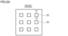
- FIG. 5A is an example of a plan view of the first or second slow cooling region.
- FIG. 5B is another example of a plan view of the first or second slow cooling region, different from FIG. 5A.
- FIG. 5C is another example of a plan view of the first or second slow cooling region, different from FIG. 5A and FIG. 5B.
- FIG. 5A is an example of a plan view of the first or second slow cooling region.
- FIG. 5D is another example of a plan view of the first or second slow cooling region, different from FIGS. 5A to 5C.
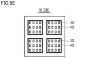
- FIG. 5E is another example of a plan view of the first or second slow cooling region, different from FIGS. 5A to 5D.
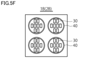
- FIG. 5F is another example of a plan view of the first or second slow cooling region, different from FIGS. 5A to 5E.
- FIG. 5G is another example of a plan view of the first or second slow cooling region, different from FIGS. 5A to 5F.
- FIG. 6 is a schematic diagram for explaining the positional relationship between the top surfaces of the convex portions in the first gentle cooling region and the top surfaces of the convex portions in the second gentle cooling region during hot press forming.
- FIG. 7 is a perspective view of a mold according to the second embodiment.
- FIG. 8 is a perspective view of a hot press-formed product formed by hot press forming using the die shown in FIG.
- FIG. 9 is a perspective view of a mold according to the third embodiment.
- FIG. 10 is a perspective view of a hot press-formed product formed by hot press forming using the die shown in FIG.
- FIG. 11 is a perspective view of a mold according to the fourth embodiment.
- FIG. 12 is a perspective view of a hot press-formed product formed by hot press forming using the die shown in FIG.
- FIG. 13 is an example of an enlarged plan view of the first or second slow cooling region in the mold of the fifth embodiment.
- the die of the present embodiment according to the first configuration is a die for performing hot press forming on a blank to form a hot press-formed product.
- This die includes an upper die having a first forming surface and a lower die having a second forming surface.
- the lower die is disposed opposite the first forming surface with the blank sandwiched therebetween, and hot press forms the blank together with the first forming surface.
- the first molding surface includes a first quenching region and a first slow cooling region.
- the first quenching region contacts the blank and cools the blank during hot press forming.
- the first slow cooling region contacts the blank and cools the blank slower than the first quenching region during hot press forming.
- the second molding surface includes a second quenching region and a second slow cooling region.
- the second quenching region is disposed opposite the first quenching region across the blank during hot press forming, and contacts the blank to cool the blank.
- the second slow cooling region is disposed opposite the first slow cooling region across the blank during hot press forming, and contacts the blank to cool the blank slower than the second quenching region.
- the contact area ratio of the first quenching region is 95% or more.
- the contact area ratio of the second quenching region is 95% or more.
- the contact area ratio of the first gentle cooling region When the ratio per unit area of the first gentle cooling region that comes into contact with the blank during hot press forming is defined as the contact area ratio of the first gentle cooling region, the contact area ratio of the first gentle cooling region is 9 to 33%.
- the contact area ratio of the second gentle cooling region When the ratio per unit area of the second gentle cooling region that comes into contact with the blank during hot press forming is defined as the contact area ratio of the second gentle cooling region, the contact area ratio of the second gentle cooling region is 9 to 33%.
- “during hot press forming” refers to the state in which the first forming surface of the upper die and the second forming surface of the lower die are in contact with the blank and applying an external force to the blank, the die is closed, and the blank is being cooled by the die while the upper die is held at the bottom dead center.
- the mold of the first configuration has two types of regions (first and second quenching regions and first and second slow cooling regions) that have different contact area ratios with the blank during hot press forming.
- the first and second slow cooling regions have a smaller contact area ratio with the blank during hot press forming compared to the first and second quenching regions. Therefore, the contact heat transfer coefficient of the first and second slow cooling regions can be made lower compared to the first and second quenching regions. Therefore, during hot press forming, the cooling rate of the blank region that is sandwiched between and in contact with the first and second slow cooling regions can be made slower than the cooling rate of the blank region that is sandwiched between and in contact with the first and second quenching regions.
- the blank region sandwiched between the first and second slow cooling regions can have a different structure from the blank region sandwiched between the first and second quenching regions.
- the blank region between the first and second slow cooling regions can be a low-strength region that is easy to plastically deform by reducing the strength of the blank region by making it a structure containing hard structure (martensite and/or bainite) and residual austenite, while the blank region between the first and second rapid cooling regions can be a high-strength region made of martensite and stronger than the low-strength region.
- each of the first and second rapid cooling regions is smooth.
- each of the first and second slow cooling regions includes a plurality of protrusions.
- the plurality of protrusions are arranged in a plurality of directions.
- the protrusions have a top surface that comes into surface contact with the blank during hot press forming.
- the top surfaces of the plurality of protrusions are arranged with gaps between each other (second configuration).
- the top surfaces of adjacent convex portions are arranged with a gap between them in each of the first and second slow cooling regions. Therefore, during hot press forming, the contact area ratio of the first and second slow cooling regions in contact with the blank is low. Furthermore, air is present in the gaps formed between the convex portions. During hot press forming, the air present in these gaps absorbs heat from the blank and retains the absorbed heat. Therefore, the contact heat transfer coefficient of the first and second slow cooling regions is reduced.
- the first and second quenching regions are smooth. Therefore, during hot press forming, the contact area ratio of the first and second quenching regions in contact with the blank is significantly higher than the contact area ratio of the first and second slow cooling regions. Furthermore, because the first and second quenching regions are smooth, air is less likely to be present. As a result, the contact heat transfer coefficient of the first and second quenching regions is significantly higher than the contact heat transfer coefficient of the first and second slow cooling regions.
- the top surface of the convex portion of the first slow cooling region at least partially overlaps with the top surface of the corresponding convex portion of the second slow cooling region (third configuration).
- the first or second slow cooling region further includes a rib portion.
- the rib portion is formed surrounding a plurality of protrusions.
- the top surface of the rib portion is disposed with a gap provided between the top surfaces of the protrusions (fourth configuration). This configuration can be applied to the mold of the third configuration (fifth configuration).
- the rib portion is formed to surround the multiple protrusions.
- the air present in the gaps between the top surfaces of the multiple protrusions is less likely to flow outside the rib portion. Therefore, the air that absorbs heat during hot press forming tends to remain inside the rib portion. This makes it possible to further reduce the contact heat transfer coefficient between the first or second slow cooling region and the blank.
- the rib portion includes a plurality of protrusions arranged in a plurality of directions, and the gap between adjacent protrusions is smaller than the gap between adjacent convex portions (sixth configuration).
- Such a configuration can be applied to the mold of the fifth configuration (seventh configuration).
- adjacent protrusions in the rib portion are arranged with a gap smaller than the gap between adjacent convex portions inside the rib portion.
- the air in the gaps between the protrusions is less likely to flow than the air in the gaps between the convex portions. Therefore, during hot press forming, the air in the gaps between the protrusions absorbs heat from the blank and tends to accumulate inside the rib portion, and the air in the gaps between the convex portions absorbs heat from the blank and tends to accumulate inside the rib portion. This makes it possible to further reduce the contact heat transfer coefficient between the first or second slow cooling region and the blank.
- the hot press molded product extends in the longitudinal direction.
- the first quenching area and the first slow cooling area are arranged in a direction corresponding to the longitudinal direction of the hot press molded product sandwiched between the upper and lower dies during hot press molding.
- the second quenching area and the second slow cooling area are arranged in a direction corresponding to the longitudinal direction of the hot press molded product sandwiched between the upper and lower dies during hot press molding (eighth configuration).
- the end (lower part) of a hot press molded product having a longitudinal direction, such as a B-pillar can be made into a low-strength area, and the remaining part can be made into a high-strength area. This makes it possible to absorb impacts at the end of the hot press molded product, while ensuring strength in the remaining part.
- the mold is one of the first to seventh configurations
- the first molding surface includes a plurality of first quenching regions and a plurality of first slow cooling regions.
- the second molding surface includes a plurality of second quenching regions and a plurality of second slow cooling regions.
- the hot press molded product extends in the longitudinal direction. In a direction corresponding to the longitudinal direction of the hot press molded product sandwiched between the upper and lower dies during hot press molding, each of the multiple first quenching regions is arranged alternately with each of the multiple first slow cooling regions. In a direction corresponding to the longitudinal direction of the hot press molded product sandwiched between the upper and lower dies during hot press molding, each of the multiple second quenching regions is arranged alternately with each of the multiple second slow cooling regions (ninth configuration).
- the die is any one of the first to seventh configurations
- the hot press molded product includes a top plate, a vertical wall, and a ridge portion connecting the top plate and the vertical wall.
- the first and second slow cooling regions are arranged at positions corresponding to the ridge portion of the hot press molded product that is sandwiched between the upper and lower dies during hot press molding.
- the first and second rapid cooling regions are arranged at positions corresponding to the top plate or vertical wall of the hot press molded product that is sandwiched between the upper and lower dies during hot press molding (tenth configuration).
- the portion corresponding to the ridge of the hot press molded product can be made into a low-strength region during hot press molding. This makes it possible to prevent wrinkles and cracks from occurring at the ridge of the hot press molded product during hot press molding.
- the hot press molded product in a mold of any one of the first to seventh configurations, includes a top plate, a pair of vertical walls, each connected to either side of the top plate and arranged opposite each other, and a pair of flanges, each connected to the vertical walls on the side opposite the top plate and protruding outward from the vertical walls.
- the first and second slow cooling regions are arranged at positions corresponding to the flanges of the hot press molded product that is sandwiched between the upper and lower dies during hot press molding.
- the first and second rapid cooling regions are arranged at positions corresponding to the top plate and vertical walls of the hot press molded product that is sandwiched between the upper and lower dies during hot press molding (eleventh configuration).
- the flange of the hot press molded product can be made into a low-strength region.
- welding such as spot welding is often performed.
- a weld heat-affected zone HAZ
- the HAZ becomes soft due to the effects of the welding heat. Therefore, if the flange is high strength, the difference in hardness between the HAZ and the part of the flange that has not been affected by the welding heat increases, making it more likely for cracks to occur.
- the flange into a low-strength region the difference in hardness between the HAZ and the part that has not been affected by the welding heat is reduced. This reduces the occurrence of cracks.
- the contact area ratio per 500 mm2 in the above mold, is 95% or more. In the second quenching region, the contact area ratio per 500 mm2 is 95% or more. In the first slow cooling region, the contact area ratio per 500 mm2 is 9 to 33%. In the second slow cooling region, the contact area ratio per 500 mm2 is 9 to 33% (twelfth configuration).
- a method for producing a hot press-formed product according to a thirteenth aspect includes the steps of preparing a blank, heating the prepared blank to a temperature of A c3 point or higher, hot press-forming the heated blank using a die having any one of the first to twelfth aspects, and releasing the hot press-formed blank from the die to produce a hot press-formed product.
- the method for producing a hot press-formed product according to the thirteenth aspect it is possible to produce a hot press-formed product having a region having high strength and a region having low strength.
- Fig. 1 is a front view showing an example of a hot press apparatus 1 for hot press molding.
- the hot press apparatus 1 has substantially the same configuration as a known hot press apparatus, except for a die 10 according to this embodiment.
- the hot press apparatus 1 includes a frame 2, a slide 3, a bolster 4, and a die 10 (upper die 11 and lower die 12).
- the vertical (up-down) direction of the hot press apparatus 1 is also referred to as the V direction
- the width direction of the hot press apparatus 1 is also referred to as the W direction
- the direction perpendicular to the V direction and the W direction is also referred to as the L direction.
- the frame 2 is disposed on the top of the hot press device 1.
- the frame 2 supports the slide 3 disposed below the frame 2 so that it can be raised and lowered.
- the frame 2 is provided with a drive device (not shown) for raising and lowering the slide 3.
- the drive device may be a mechanical mechanism or a hydraulic mechanism.
- the slide 3 is attached to the frame 2, and can be raised and lowered in the vertical direction by the drive device provided in the frame 2.
- An upper die 11 is attached to the lower surface of the slide 3.
- the bolster 4 is disposed below the slide 3.
- the upper surface of the bolster 4 faces the lower surface of the slide 3.
- a lower die 12 is attached to the upper surface of the bolster 4. At this time, the lower die 12 is disposed below the upper die 11.
- the mold 10 includes the above-mentioned upper mold 11 and the above-mentioned lower mold 12.
- the upper mold 11 and the lower mold 12 extend in the L direction, as an example.
- the shapes of the upper mold 11 and the lower mold 12 are not particularly limited.
- the upper die 11 is fixed to the lower surface of the slide 3, and the lower die 12 is fixed to the upper surface of the bolster 4.
- the lower die 12 is disposed below the upper die 11.
- hot press forming a heated blank is first placed on the lower die 12. After the blank is placed, the upper die 11 slides in the V direction relative to the lower die 12, and applies an external force to the blank while sandwiching and contacting the blank. In other words, the upper die 11 and the lower die 12 hot press form the blank. This forms the blank into a desired shape. Furthermore, during hot press forming, the forming surfaces of the upper die 11 and the lower die 12 come into contact with the blank, and the upper die 11 and the lower die 12 remove heat from the blank and quench it. As a result, a hot press formed product having a desired shape and increased strength is manufactured.
- the hot press device 1 may include other configurations not shown in FIG. 1.
- the hot press device 1 may include, for example, a cooling device for cooling the die 10. In this case, for example, a flow path through which a cooling medium passes is provided inside the die 10. Furthermore, a pump is disposed inside the die 10 for supplying the cooling medium.
- the hot press device 1 may further include a transport mechanism for transporting material to the hot press device 1.
- the hot press device 1 may include a configuration not shown in FIG. 1 that is included in a known hot press device.
- Fig. 2 is a perspective view of the mold 10 in Fig. 1.
- the upper mold 11 has a first molding surface 110.
- the first molding surface 110 is disposed on the lower surface of the upper mold 11.
- the first molding surface 110 includes a valley-shaped surface 110a extending in the longitudinal direction (L direction) of the upper mold 11 at the center in the width direction of the upper mold 11.
- the lower die 12 has a second molding surface 120.
- the second molding surface 120 is disposed on the upper surface of the lower die 12.
- the second molding surface 120 includes a mountain-shaped surface 120a extending in the longitudinal direction (L direction) of the lower die 12 at the center of the width direction of the lower die 12.
- L direction longitudinal direction
- the second molding surface 120 is disposed opposite the first molding surface 110, sandwiching the blank 60 therebetween.
- the second molding surface 120 together with the first molding surface 110, sandwiches the blank 60 while in contact with it, and performs hot press forming.
- the first molding surface 110 includes a first quenching region 1A and a first slow cooling region 1B indicated by a shaded area.
- the first slow cooling region 1B is formed in a part of the first molding surface 110, and the remaining part of the first molding surface 110 is the first quenching region 1A.
- the first quenching region 1A and the first slow cooling region 1B are arranged in the longitudinal direction (L direction) of the mold 10 (upper mold 11).
- the second molding surface 120 includes a second rapid cooling region 2A and a second slow cooling region 2B indicated by the shaded area.
- the second slow cooling region 2B is formed in a portion of the second molding surface 120, and the remaining portion of the second molding surface 120 is the second rapid cooling region 2A.
- the second rapid cooling region 2A and the second slow cooling region 2B are arranged in the longitudinal direction (L direction) of the mold 10 (lower mold 12).
- the second quenching area 2A is positioned opposite the first quenching area 1A with the blank in between.
- the second slow cooling area 2B is positioned opposite the second quenching area 2A with the blank in between.
- the first and second forming surfaces 110 and 120 do not have any injection holes for injecting a cooling medium such as water. During hot press forming, the first and second forming surfaces 110 and 120 come into contact with the blank 60 to remove heat from the blank 60 without directly supplying the cooling medium to the blank 60.
- the upper die 11 and lower die 12 of the die 10 come into contact with the blank 60 during hot press forming, thereby removing heat from the blank 60.
- the blank 60 is sandwiched between the upper die 11 and lower die 12 and formed, and is also cooled by the upper die 11 and lower die 12.
- the blank region sandwiched between the first and second quenching regions 1A, 2A is cooled faster than the blank region sandwiched between the first and second slow cooling regions 1B, 2B. Therefore, in the hot press molded product 61, the region 61A molded between the first and second quenching regions 1A, 2A becomes a high-strength region having high strength.
- the blank 60 the blank region sandwiched between the first and second slow cooling regions 1B, 2B is cooled slower than the blank region sandwiched between the first and second quenching regions 1A, 2A. Therefore, in the hot press molded product 61, the region 61B molded between the first and second slow cooling regions 1B, 2B forms a low strength region 61B that has lower strength than the high strength region 61A and is prone to plastic deformation.
- the first and second quenching regions 1A, 2A and the first and second slow cooling regions 1B, 2B of the mold 10 will be described.
- the proportion of the portion of the first quenching region that contacts the blank 60 during hot press forming per unit area is defined as the contact area ratio (%) of the first quenching region.
- the proportion of the portion of the second quenching region that contacts the blank 60 during hot press forming per unit area is defined as the contact area ratio (%) of the second quenching region.
- the contact area ratio of the first quenching region 1A is 95% or more. Also, the contact area ratio of the second quenching region 2A is 95% or more. In other words, during hot press forming, almost the entire surface of the first quenching region 1A and almost the entire surface of the second quenching region 2A are in contact with the blank 60. Therefore, the first and second quenching regions 1A and 2A cool the blank 60 during hot press forming by removing heat.
- the contact area ratio of the first and second quenching regions 1A and 2A is less than 95% during hot press forming, a sufficient contact heat transfer coefficient cannot be obtained with the blank 60.
- the cooling rate of the blank region sandwiched between the first and second quenching regions 1A and 2A during hot press forming is not fast enough. Therefore, a high-strength martensite structure cannot be obtained sufficiently in the region 61A of the hot press formed product 61 sandwiched between the first and second quenching regions 1A and 2A during hot press forming.
- the contact area ratio of the first and second quenching regions 1A and 2A is set to 95% or more.
- the region 61A of the hot press-formed product 61 sandwiched between the first and second quenching regions 1A and 2A during hot press forming becomes a high-strength region in which a high-strength martensite structure is sufficiently obtained.
- the proportion per unit area of the first slow cooling region 1B that comes into contact with the blank 60 during hot press forming is defined as the contact area ratio (%) of the first slow cooling region 1B.
- the proportion per unit area of the second slow cooling region 2B that comes into contact with the blank 60 during hot press forming is defined as the contact area ratio (%) of the second slow cooling region 2B.
- the contact area ratio of the first slow cooling region 1B is 9-33%.
- the contact area ratio of the second slow cooling region 2B is 9-33%.
- the amount of heat dissipated from the first and second slow cooling regions 1B and 2B during hot press forming is significantly less than the amount of heat dissipated from the first and second rapid cooling regions 1A and 2A.
- the cooling rate of the blank region sandwiched between the first and second slow cooling regions 1B and 2B is slower than the cooling rate of the blank region sandwiched between the first and second rapid cooling regions 1A and 2A.
- the contact heat transfer coefficient with the blank 60 will be excessively low.
- the cooling rate of the blank region sandwiched between the first and second slow cooling regions 1B, 2B during hot press forming will be excessively slow.
- the strength will be excessively low or pro-eutectoid ferrite, which will be the starting point of fracture, will be generated in region 61B of the hot press formed product 61 sandwiched between the first and second slow cooling regions 1B, 2B during hot press forming.
- region 61B of the hot press formed product 61 sandwiched between the first and second slow cooling regions 1B, 2B during hot press forming will have a structure in which hard structure (bainite or martensite) and retained austenite are mixed in appropriate amounts, and will be a low-strength region that has lower strength and is more susceptible to plastic deformation than region 61A.
- the contact area ratio of each of the first and second quenching regions 1A and 2A is 95% or more, and the contact area ratio of each of the first and second slow cooling regions is 9 to 33%.
- the cooling rate of the blank region sandwiched between the first and second quenching regions 1A and 2A becomes faster, and the cooling rate of the blank region sandwiched between the first and second slow cooling regions 1B and 2B becomes slower.
- the region 61A of the hot press molded product 61 molded between the first and second quenching regions 1A and 2A becomes a high-strength region
- the region 61B molded between the first and second slow cooling regions 1B and 2B becomes a low-strength region that has a lower strength than the high-strength region and is prone to plastic deformation. Therefore, a hot press molded product 61 having both a high-strength region and a low-strength region can be manufactured.
- FIG. 4 is an example of a plan view of the first or second quenching region 1A or 2A. In this specification, a plan view shows the appearance when a target surface or region is developed into a plane. Referring to Figure 4, the first or second quenching region 1A or 2A is smooth.
- first and second slow cooling regions 1B and 2B As long as the contact area ratio of the first and second slow cooling regions 1B and 2B is 9 to 33%, the shape of the first and second slow cooling regions 1B and 2B is not particularly limited.
- Fig. 5A is an example of a plan view of the first or second slow cooling region 1B or 2B.
- the first slow cooling region 1B includes a plurality of convex portions 30.
- the convex portions 30 protrude in the normal direction of the first forming surface 110.
- the second slow cooling region 2B includes a plurality of convex portions 30.
- the convex portions 30 protrude in the normal direction of the second forming surface 120.
- Each convex portion 30 has a top surface 31.
- the top surface 31 is flat.
- the multiple top surfaces 31 are in surface contact with the blank 20 during hot press forming.
- the top surfaces 31 of the multiple convex portions 30 are arranged with gaps between them.
- gaps are formed between adjacent top surfaces 31, and air is present in the gaps.
- air is present in the gaps between adjacent protrusions 30.
- the top surface 31 of the convex portion 30 is rectangular, and the convex portion 30 is substantially rectangular.
- the shape of the convex portion 30 is not limited to this.
- the top surface 31 of the convex portion 30 may be circular, and the convex portion 30 may be cylindrical.
- the top surface 31 of the convex portion 30 may be a rectangle that is longer than the top surface 31 in FIG. 5A.
- the multiple protrusions 30 are not arranged in one direction, but are arranged in multiple directions. By arranging the multiple protrusions 30 in multiple directions, but not in only one direction, temperature variation during cooling is suppressed in the blank region in contact with the first and second slow cooling regions 1B, 2B.
- the size of the protrusion 30 is not particularly limited.
- the height of the protrusion 30 is 0.1 to 5.0 mm.
- the maximum length of the top surface 31 of the protrusion 30 is 1 to 8 mm.
- the aspect ratio of the top surface 31 is, for example, 5.0 or less.
- the area of the top surface 31 of the protrusion 30 is, for example, 100 mm2 or less.
- the first slow cooling region 1B includes a plurality of convex portions 30 and a rib portion 40.
- the second slow cooling region 2B includes a plurality of convex portions 30 and a rib portion 40.
- the rib portion 40 is arranged around the plurality of convex portions 30, surrounding the plurality of convex portions 30.
- the rib portion 40 has a top surface 41.
- the top surface 41 is flat.
- the top surface 41, together with the plurality of top surfaces 31, comes into surface contact with the blank 20 during hot press forming.
- the top surface 41 of the rib portion 40 is arranged with a gap provided between it and the top surfaces 31 of the plurality of convex portions 30.
- the rib portion 40 is formed so as to surround the multiple protrusions 30 in a plan view. Therefore, the air present in the gaps between the multiple top surfaces 31 is unlikely to flow out of the rib portion 40. Therefore, the air that absorbs heat during hot press forming tends to remain inside the rib portion 40. This allows the heat absorbed by the air to be retained for a longer period of time. As a result, the contact heat transfer coefficient with the blank 60 can be further reduced.
- the first or second slow cooling region 1B or 2B may include a plurality of rib portions 40.
- the rib portion 40 is rectangular in a plan view.
- the shape of the rib portion 40 is not limited to this.
- the rib portion 40 may be circular.
- the rib portion 40 does not have to completely surround the plurality of protrusions 30.
- the rib portion 40 may include a plurality of divided rib portions 42 and 43, and a gap may be formed between the adjacent divided rib portions 42 and 43.
- the rib portion 40 may be composed of a plurality of divided rib portions, and the shape of the rib portion 40 is not particularly limited.
- the shape of the first and second slow cooling regions 1B, 2B is not particularly limited as long as the contact area ratio of each of the first and second slow cooling regions 1B, 2B is 9 to 33%.
- the first and second slow cooling regions 1B, 2B include multiple protrusions 30, or multiple protrusions 30 and one or more rib portions 40, as shown in Figures 5A to 5G.
- the top surface 31 of the convex portion 30 of the first slow cooling region 1B at least partially overlaps with the top surface 31 of the convex portion 30 of the second slow cooling region 2B.
- FIG. 6 shows the state when the first and second slow cooling regions 1B and 2B are developed on a plane, with the top surface 31 of the convex portion 30 of the first slow cooling region 1B shown by a solid line and the top surface 31 of the convex portion 30 of the second slow cooling region 2B shown by a dashed line.
- the convex portion 30 of the second slow cooling region 2B enters between the adjacent convex portions 30 of the first slow cooling region 1B, thereby suppressing the occurrence of wavy deformation of the blank 60 due to the convex portions 30.
- the contact area ratio per 500 mm2 is 9 to 33%.
- the contact area ratio per 500 mm2 is 9 to 33%.
- a plurality of minute protrusions 30 are formed to such an extent that the contact area ratio per 500 mm2 falls within the above-mentioned range. Therefore, in the first and second slow cooling regions 1B, 2B, the contact heat transfer coefficient is reduced, and temperature variation in the blank regions in contact with the first and second slow cooling regions 1B, 2B can be suppressed.
- the first quenching region 1A in contact with the blank during hot press forming has a contact area ratio of 95% or more per 500 mm2 .
- the second quenching region 2A in contact with the blank during hot press forming has a contact area ratio of 95% or more per 500 mm2 .
- the contact area ratio of each region can be grasped, for example, by the following method. Pressure-sensitive paper is placed between the upper and lower dies, and the upper die is lowered to the bottom dead center. The upper die is then raised to remove the pressure-sensitive paper, and the removed pressure-sensitive paper is cut into a plurality of rectangular pieces.
- the area of each rectangular piece is, for example, 500 mm2 .
- the size of each rectangular piece is preferably, for example, ⁇ 500 mm (22.36 mm) in length and ⁇ 500 mm (22.36 mm) in width. Then, the area of the part where the color tone has changed is measured for each rectangular piece.
- the contact area ratio of each region can be grasped from the area of the part where the color tone has changed and the area of the rectangular piece.
- the hot press-molded product 61 shown in FIG. 3 is molded by using the mold 10 shown in FIG. 2.
- the hot press-molded product 61 extends in the longitudinal direction.
- the first rapid cooling region 1A and the first slow cooling region 1B are arranged in the L direction, which corresponds to the longitudinal direction of the hot press-molded product 61 that is sandwiched between the upper die 11 and the lower die 12 during hot press molding.
- the second rapid cooling region 2A and the second slow cooling region 2B are also arranged in the L direction.
- the hot press-formed product 61 is, for example, an automobile part such as a B-pillar.
- the end of the hot press-formed product 61 having such a longitudinal direction (for example, the lower part of the B-pillar) can be made into a low-strength area that has low strength and is easy to plastically process, and the remaining part can be made into a high-strength area. This makes it possible to make the end of the hot press-formed product 61 capable of absorbing impacts, while ensuring strength in the remaining part.
- the multiple first quenching regions 1A of the first molding surface 710 are arranged alternately with the multiple first slow cooling regions 1B of the first molding surface 710.
- the multiple second quenching regions 2A of the second molding surface 720 are also arranged alternately with the multiple second slow cooling regions 2B of the second molding surface 720. Note that, during hot press molding, each of the first quenching regions 1A is disposed opposite the corresponding second quenching region 2A across the blank 60. Also, during hot press molding, each of the first slow cooling regions 1B is disposed opposite the corresponding second slow cooling region 2B across the blank 60.
- the hot press-formed product 62 shown in FIG. 8 is, for example, a front side member.
- hot press forming is performed using the die 70 of the second embodiment, for example, multiple high strength regions are arranged alternately with multiple low strength regions in the longitudinal direction of the hot press-formed product 62. Therefore, excellent shock absorbing properties are obtained in the entire hot press-formed product 62.
- FIG. 10 is a perspective view of a hot press-formed product 63 formed by hot press forming using the die 80 of FIG. 9.
- the hot press-formed product 63 includes a top plate 631, a pair of vertical walls 632, and a pair of ridge portions 633.
- the pair of vertical walls 632 are disposed on both sides of the top plate 631 and face each other.
- Each of the pair of ridge portions 633 connects the top plate 631 and the corresponding vertical wall 632.
- the ridgeline 633 connecting the top plate 631 and the vertical wall 632 is the region that is most strained during hot press forming. As a result, wrinkles and cracks are likely to occur at the ridgeline 633. Therefore, in the hot press formed product 63, the ridgeline 633 is made into a low strength region 63B. In this case, the ridgeline 633 has a soft structure, and therefore has increased plastic deformability. As a result, the occurrence of wrinkles and cracks due to hot press forming can be suppressed.
- the first slow cooling region 1B and the second slow cooling region 2B are positioned on the corresponding first forming surface 810 and second forming surface 820 at positions that correspond to the ridgeline portion 633 of the hot press formed hot press formed product 63 so that the ridgeline portion 633 of the hot press formed hot press formed product 63 becomes a low strength region.
- the ridgeline portion 633 of the hot press-formed product 63 can be made into a low-strength region that has low strength and is prone to plastic deformation during hot press forming. Therefore, the occurrence of wrinkles and cracks in the ridgeline portion 633 of the hot press-formed product 63 during hot press forming can be suppressed.
- FIG. 11 is a perspective view of a mold 90 of the fourth embodiment.
- the mold 90 includes an upper mold 91 and a lower mold 92.
- the upper mold 91 has a first molding surface 910.
- the lower mold 92 has a second molding surface 920.
- the first molding surface 910 includes a first rapid cooling region 1A and a first slow cooling region 1B.
- the second molding surface 920 includes a second rapid cooling region 2A and a second slow cooling region 2B.
- FIG. 12 is a perspective view of a hot press-formed product 64 formed by hot press forming using the die 90 of FIG. 11.
- the hot press-formed product 64 includes a top plate 631, a pair of vertical walls 632, and a pair of flanges 634.
- Each of the pair of flanges 634 is connected to the vertical wall 632 on the side opposite the top plate 631, and protrudes outward from the vertical wall 632.
- the flange 634 is made to be the low strength region 64B.
- the flange 634 becomes a soft structure with low strength. Therefore, it is possible to suppress the difference in strength between the HAZ formed after welding and the region not affected by the heat of welding. As a result, it is possible to suppress the occurrence of cracks due to the difference in strength.
- the first slow cooling region 1B and the second slow cooling region 2B are positioned on the corresponding first forming surface 910 and second forming surface 920 at positions corresponding to the flange 634 of the hot press formed hot press formed product 64 so that the flange 634 of the hot press formed product 64 becomes the low strength region 64B.
- the flange 634 of the hot press-formed product 64 can be made into a low-strength region during hot press forming. Therefore, when the hot press-formed product 64 is welded, the occurrence of cracks in the flange 634 can be suppressed.
- the configuration of the rib portion 40 formed to surround the multiple protrusions 30 is different from that of the first to fourth embodiments.
- the mold of the fifth embodiment will be described below.
- FIG. 13 is an example of an enlarged plan view of the first or second slow cooling region 1B, 2B in the mold of the fifth embodiment.
- FIG. 13 shows some of the multiple convex portions 30 and some of the rib portion 40.
- the rib portion 40 includes multiple protrusions 44.
- the protrusions 44 protrude in the normal direction of the first molding surface 110.
- the protrusions 44 protrude in the normal direction of the second molding surface 120.
- the multiple protrusions 44 are arranged with tiny gaps c44 between them. In other words, tiny gaps c44 are formed between adjacent protrusions 44.
- the gaps c44 between the protrusions 44 are smaller than the gaps c30 between adjacent convex portions 30.
- the gaps c44 are the smallest gaps between the protrusions 44.
- the gaps c30 are the smallest gaps between the convex portions 30.
- the multiple protrusions 44 are not arranged in one direction, but in multiple directions.
- Each protrusion 44 has a top surface 441.
- the top surfaces 441 are flat. The multiple top surfaces 441 come into surface contact with the blank 20 during hot press forming.
- adjacent protrusions 44 in the rib portion 40 are arranged with a gap c44 that is smaller than the gap c30 between adjacent convex portions 30 inside the rib portion 44.
- the air present in the gap c44 between the protrusions 44 is less likely to flow than the air present in the gap c30 between the convex portions 30. Therefore, during hot press forming, the air present in the gap c44 between the protrusions 44 tends to absorb heat from the blank 60 and accumulate inside the rib portion 40, and the air present in the gap c30 between the convex portions 30 tends to absorb heat from the blank 60 and accumulate inside the rib portion 40.
- the surface area of the rib portion 40 is increased by the multiple protrusions 44 compared to when the top surface 441 of the rib portion 40 is flat over the entire area of the rib portion 40. Therefore, during hot press forming, heat conducted to the rib portion 40 (multiple protrusions 44) through contact with the blank 60 is easily transferred to the air present in the gaps c44 between the protrusions 44, and this air tends to become hot. This makes it possible to further reduce the contact heat transfer coefficient between the first or second slow cooling region 1B, 2B and the blank 60.
- the top surface 441 of the protrusion 44 is rectangular, and the protrusion 44 is substantially rectangular.
- the shape of the protrusion 44 is not limited to this.
- the top surface 441 of the protrusion 44 may be circular, and the protrusion 44 may be cylindrical.
- the top surface 441 of the protrusion 44 may be a rectangle that is longer than the top surface 441 in FIG. 13.
- the area of the top surface 441 of the protrusion 44 is smaller than the area of the top surface 30 of the convex portion 30.
- the area of the top surface 441 of the protrusion 44 may be the same as the area of the top surface 30 of the convex portion 30, or may be larger than the area of the top surface 30 of the convex portion 30, as long as the gap c44 between the protrusions 44 is smaller than the gap c30 between the convex portions 30.
- Step 1 Preparation step (Step 2) Heating step (Step 3) Hot press molding step (Step 4) Demolding step
- a blank 60 having a desired chemical composition is prepared.
- the blank 60 is not particularly limited.
- the blank 60 is, for example, a steel plate.
- the type of the steel plate is not particularly limited.
- the blank 60 may be, for example, a steel plate that has been subjected to a surface treatment such as plating, or may be a steel plate that has not been subjected to a surface treatment such as plating (so-called bare material).
- the plating may be a hot-dip galvanizing treatment, a hot-dip galvannealing treatment, or an aluminum plating treatment.
- the thickness of the blank 60 is not particularly limited, but is selected according to the characteristics of the hot press-formed product to be obtained.
- the thickness of the blank 60 is, for example, 0.6 to 3.2 mm.
- the mechanical properties of the blank 60 are also not particularly limited. The mechanical properties of the blank 60 are appropriately selected according to the characteristics of the hot press-formed product to be obtained.
- the method of preparing the blank 60 is not particularly limited.
- the blank 60 may be manufactured from molten steel having the desired chemical composition by a known manufacturing method.
- the blank 60 may also be prepared by purchasing a blank 60 manufactured by a third party.
- the prepared blank 60 is heated to a temperature of A c3 point or higher.
- the method of heating the blank 60 is not particularly limited.
- the blank 60 may be heated using a heating furnace such as an electric furnace, a gas furnace, a far-infrared furnace, or a near-infrared furnace.
- the blank 60 may also be heated using an electric heating device, a high-frequency induction heating device, or the like.
- the method of heating the blank 60 is not limited, and a known heating method may be appropriately selected.
- the blank 60 heated to point A c3 or higher is hot press formed using the above-mentioned mold (10, 70, 80 or 90).
- the hot press forming process the blank 60 heated in the heating process is placed on the second forming surface of the lower mold 12. Then, the upper mold 11 is brought relatively close to the lower mold 12, and the mold 10 is closed. At this time, the blank 60 comes into contact with the first forming surface of the upper mold 11 and the second forming surface of the lower mold 12. In other words, the blank 60 is sandwiched between the first forming surface of the upper mold 11 and the second forming surface of the lower mold 12.
- the blank 60 is hot press formed by the upper mold 11 and the lower mold 12.
- a cooling medium is not directly supplied to the blank 60 during hot press forming.
- the blank 60 is heat-dissipated by the die 10 that contacts the blank 60 during hot press forming.
- the first and second quenching regions 1A and 2A are arranged opposite each other across the blank 60, and the first and second quenching regions 1A and 2A contact the blank 60.
- the first and second slow cooling regions 1B and 2B are arranged opposite each other across the blank 60, and the first and second slow cooling regions 1B and 2B contact the blank 60.
- the temperatures of the upper die 11 and the lower die 12 are sufficiently lower than the temperature of the blank 60.
- the blank 60 is heat-dissipated by the first and second quenching regions 1A, 2A and the first and second slow cooling regions 1B, 2B. At this time, the blank area sandwiched between the first and second rapid cooling areas 1A, 2A cools faster than the blank area sandwiched between the first and second slow cooling areas 1B, 2B.
- the hot press-formed blank 60 is demolded from the die 10 to produce a hot press-formed product.
- the temperature of the blank when it is demolded from the die 10 is defined as the cooling stop temperature.
- the cooling stop temperature of the blank region sandwiched between the first and second slow cooling regions 1B and 2B is between the Mf point and the Ms point, or between the Ms point and 500°C, the region sandwiched between the first and second slow cooling regions 1B and 2B of the hot press-formed product becomes a soft structure in which a hard structure (martensite and bainite, or bainite) and residual austenite are mixed.
- the region sandwiched between the first and second slow cooling regions 1B and 2B of the hot press-formed product has low strength and becomes a low-strength region that is easily plastically deformed.
- the region sandwiched between the first and second quenching regions 1A and 2A of the hot press-formed product has a faster cooling rate than the region sandwiched between the first and second slow cooling regions 1B and 2B. Therefore, the region of the hot press-formed product sandwiched between the first and second quenching regions 1A, 2A becomes a high-strength region having strength higher than that of the low-strength region.
- the Ms and Mf points of the blank 60 differ depending on the chemical composition of the blank 60. Therefore, when forming a high-strength region and a low-strength region in a hot press molded product using the blank 60 as a material, the preferred cooling stop temperature differs depending on the chemical composition of the blank 60. However, by heat transfer simulation or experiment, the cooling rate, temperature change over time, and temperature distribution in the blank region sandwiched between the first and second slow cooling regions 1B and 2B of the blank 60 can be obtained. Therefore, by these heat transfer simulations or experiments, the preferred cooling stop temperature or the time from the start of hot press molding to demolding can be obtained. Therefore, according to the mold of this embodiment, a hot press molded product including a high-strength region and a low-strength region can be manufactured by hot press molding according to the chemical composition of the blank 60.
Landscapes
- Engineering & Computer Science (AREA)
- Mechanical Engineering (AREA)
- Chemical & Material Sciences (AREA)
- Physics & Mathematics (AREA)
- Thermal Sciences (AREA)
- Crystallography & Structural Chemistry (AREA)
- Materials Engineering (AREA)
- Metallurgy (AREA)
- Organic Chemistry (AREA)
- Shaping Metal By Deep-Drawing, Or The Like (AREA)
- Molds, Cores, And Manufacturing Methods Thereof (AREA)
- Mounting, Exchange, And Manufacturing Of Dies (AREA)
Priority Applications (1)
| Application Number | Priority Date | Filing Date | Title |
|---|---|---|---|
| JP2025514001A JP7730075B2 (ja) | 2023-04-11 | 2024-04-11 | 金型、及び熱間プレス成形品の製造方法 |
Applications Claiming Priority (2)
| Application Number | Priority Date | Filing Date | Title |
|---|---|---|---|
| JP2023063809 | 2023-04-11 | ||
| JP2023-063809 | 2023-04-11 |
Publications (1)
| Publication Number | Publication Date |
|---|---|
| WO2024214765A1 true WO2024214765A1 (ja) | 2024-10-17 |
Family
ID=93059478
Family Applications (1)
| Application Number | Title | Priority Date | Filing Date |
|---|---|---|---|
| PCT/JP2024/014643 Ceased WO2024214765A1 (ja) | 2023-04-11 | 2024-04-11 | 金型、及び熱間プレス成形品の製造方法 |
Country Status (2)
| Country | Link |
|---|---|
| JP (1) | JP7730075B2 (https=) |
| WO (1) | WO2024214765A1 (https=) |
Cited By (1)
| Publication number | Priority date | Publication date | Assignee | Title |
|---|---|---|---|---|
| CN117177825A (zh) * | 2021-03-30 | 2023-12-05 | 日本制铁株式会社 | 模具和热压成形品的制造方法 |
Citations (6)
| Publication number | Priority date | Publication date | Assignee | Title |
|---|---|---|---|---|
| JP2006104527A (ja) * | 2004-10-06 | 2006-04-20 | Nippon Steel Corp | 高強度部品の製造方法と高強度部品 |
| JP4542439B2 (ja) * | 2005-01-21 | 2010-09-15 | 新日本製鐵株式会社 | 金属板材の熱間プレス成形方法およびその装置 |
| JP2015226936A (ja) * | 2009-09-01 | 2015-12-17 | ティッセンクルップ スチール ヨーロッパ アクチェンゲゼルシャフトThyssenKrupp Steel Europe AG | 金属構造コンポーネントの製造方法および製造装置 |
| JP6424195B2 (ja) * | 2016-11-14 | 2018-11-14 | 株式会社豊田中央研究所 | 熱間プレス成形方法 |
| WO2022065465A1 (ja) * | 2020-09-28 | 2022-03-31 | 日本製鉄株式会社 | 金型及びプレス成形品の製造方法 |
| WO2022210874A1 (ja) * | 2021-03-30 | 2022-10-06 | 日本製鉄株式会社 | 金型及び熱間プレス成形品の製造方法 |
Family Cites Families (5)
| Publication number | Priority date | Publication date | Assignee | Title |
|---|---|---|---|---|
| CA3057804C (en) | 2017-03-24 | 2020-04-07 | Nippon Steel Corporation | Hat member |
| JP2019122984A (ja) | 2018-01-16 | 2019-07-25 | 高周波熱錬株式会社 | ホットプレス用鋼板の加熱方法及びホットプレス品の製造方法 |
| JP7214973B2 (ja) | 2018-03-30 | 2023-01-31 | マツダ株式会社 | 熱間プレス加工方法及び加工装置 |
| MX2022012385A (es) | 2020-04-03 | 2022-10-18 | Nippon Steel Corp | Aparato de prensado en caliente y metodo para fabricar un producto formado por prensado en caliente. |
| EP4129520A4 (en) | 2020-04-03 | 2023-09-20 | Nippon Steel Corporation | HOT PRESSING LINE AND METHOD FOR MANUFACTURING A HOT PRESSING MOLDED ARTICLE |
-
2024
- 2024-04-11 JP JP2025514001A patent/JP7730075B2/ja active Active
- 2024-04-11 WO PCT/JP2024/014643 patent/WO2024214765A1/ja not_active Ceased
Patent Citations (6)
| Publication number | Priority date | Publication date | Assignee | Title |
|---|---|---|---|---|
| JP2006104527A (ja) * | 2004-10-06 | 2006-04-20 | Nippon Steel Corp | 高強度部品の製造方法と高強度部品 |
| JP4542439B2 (ja) * | 2005-01-21 | 2010-09-15 | 新日本製鐵株式会社 | 金属板材の熱間プレス成形方法およびその装置 |
| JP2015226936A (ja) * | 2009-09-01 | 2015-12-17 | ティッセンクルップ スチール ヨーロッパ アクチェンゲゼルシャフトThyssenKrupp Steel Europe AG | 金属構造コンポーネントの製造方法および製造装置 |
| JP6424195B2 (ja) * | 2016-11-14 | 2018-11-14 | 株式会社豊田中央研究所 | 熱間プレス成形方法 |
| WO2022065465A1 (ja) * | 2020-09-28 | 2022-03-31 | 日本製鉄株式会社 | 金型及びプレス成形品の製造方法 |
| WO2022210874A1 (ja) * | 2021-03-30 | 2022-10-06 | 日本製鉄株式会社 | 金型及び熱間プレス成形品の製造方法 |
Cited By (1)
| Publication number | Priority date | Publication date | Assignee | Title |
|---|---|---|---|---|
| CN117177825A (zh) * | 2021-03-30 | 2023-12-05 | 日本制铁株式会社 | 模具和热压成形品的制造方法 |
Also Published As
| Publication number | Publication date |
|---|---|
| JPWO2024214765A1 (https=) | 2024-10-17 |
| JP7730075B2 (ja) | 2025-08-27 |
Similar Documents
| Publication | Publication Date | Title |
|---|---|---|
| JP4833323B2 (ja) | 車両用メンバー製作方法及びこれを利用したサイドメンバー | |
| CN109072322B (zh) | 具有至少两个强度不同的区域的汽车组件的制备方法 | |
| JP6376318B1 (ja) | ハット部材およびその製造方法 | |
| CN101688264B (zh) | 制造局部硬化的成型件的方法、局部硬化的成型件以及局部硬化的成型件的应用 | |
| CN102084011B (zh) | 通过差温致冷从坯料成形硬化材料的方法 | |
| US8349100B2 (en) | Method for press-molding embossed steel plate | |
| JP6288378B2 (ja) | パネル状成形品、車両用ドア、及び、パネル状成形品の製造方法 | |
| JP7477809B2 (ja) | 金型及び熱間プレス成形品の製造方法 | |
| JP7730075B2 (ja) | 金型、及び熱間プレス成形品の製造方法 | |
| US12042840B2 (en) | Hot press processing method and processing device | |
| JP7622052B2 (ja) | 車両フレームのための成形板金部品および対応する製造方法 | |
| JP5137323B2 (ja) | バンパー補強部材の製造方法 | |
| JP2019500215A (ja) | 乗り物用鋼構成部品の製造方法 | |
| JP7155986B2 (ja) | 鋼板部材及びその製造方法 | |
| KR101328409B1 (ko) | 자동차용 필러 부재 | |
| KR20140122019A (ko) | 국부 연화가 가능한 핫 스탬핑 성형장치 및 성형방법 | |
| JP2019217542A (ja) | 部分的に強度が異なる車体部材の製造方法及びこれに用いる金型 | |
| CN115362038A (zh) | 热压装置和热压成形品的制造方法 | |
| KR101461742B1 (ko) | 다른 두께를 갖는 접합강판을 위한 핫 프레스 포밍 방법 | |
| KR20220096878A (ko) | 패치워크 블랭크의 핫스탬핑 방법 | |
| KR101159895B1 (ko) | 프레스 경화용 금형의 냉각장치 및 이에 의한 자동차 부품의 제조방법 | |
| WO2012043836A1 (ja) | プレス成形品およびその製造方法 | |
| KR20250105550A (ko) | 핫스탬핑용 고주파 유도 가열장치 |
Legal Events
| Date | Code | Title | Description |
|---|---|---|---|
| 121 | Ep: the epo has been informed by wipo that ep was designated in this application |
Ref document number: 24788788 Country of ref document: EP Kind code of ref document: A1 |
|
| WWE | Wipo information: entry into national phase |
Ref document number: 2025514001 Country of ref document: JP |
|
| NENP | Non-entry into the national phase |
Ref country code: DE |
|
| 122 | Ep: pct application non-entry in european phase |
Ref document number: 24788788 Country of ref document: EP Kind code of ref document: A1 |