WO2024214359A1 - 突起部材、配管部材、配管システム - Google Patents
突起部材、配管部材、配管システム Download PDFInfo
- Publication number
- WO2024214359A1 WO2024214359A1 PCT/JP2024/001851 JP2024001851W WO2024214359A1 WO 2024214359 A1 WO2024214359 A1 WO 2024214359A1 JP 2024001851 W JP2024001851 W JP 2024001851W WO 2024214359 A1 WO2024214359 A1 WO 2024214359A1
- Authority
- WO
- WIPO (PCT)
- Prior art keywords
- pipe
- protruding
- straight pipe
- protrusion
- central axis
- Prior art date
- Legal status (The legal status is an assumption and is not a legal conclusion. Google has not performed a legal analysis and makes no representation as to the accuracy of the status listed.)
- Ceased
Links
Images


Classifications
-
- E—FIXED CONSTRUCTIONS
- E04—BUILDING
- E04D—ROOF COVERINGS; SKY-LIGHTS; GUTTERS; ROOF-WORKING TOOLS
- E04D13/00—Special arrangements or devices in connection with roof coverings; Protection against birds; Roof drainage ; Sky-lights
- E04D13/04—Roof drainage; Drainage fittings in flat roofs, balconies or the like
- E04D13/08—Down pipes; Special clamping means therefor
- E04D2013/0833—Elbow pieces
-
- F—MECHANICAL ENGINEERING; LIGHTING; HEATING; WEAPONS; BLASTING
- F16—ENGINEERING ELEMENTS AND UNITS; GENERAL MEASURES FOR PRODUCING AND MAINTAINING EFFECTIVE FUNCTIONING OF MACHINES OR INSTALLATIONS; THERMAL INSULATION IN GENERAL
- F16L—PIPES; JOINTS OR FITTINGS FOR PIPES; SUPPORTS FOR PIPES, CABLES OR PROTECTIVE TUBING; MEANS FOR THERMAL INSULATION IN GENERAL
- F16L55/00—Devices or appurtenances for use in, or in connection with, pipes or pipe systems
- F16L55/02—Energy absorbers; Noise absorbers
- F16L55/027—Throttle passages
-
- Y—GENERAL TAGGING OF NEW TECHNOLOGICAL DEVELOPMENTS; GENERAL TAGGING OF CROSS-SECTIONAL TECHNOLOGIES SPANNING OVER SEVERAL SECTIONS OF THE IPC; TECHNICAL SUBJECTS COVERED BY FORMER USPC CROSS-REFERENCE ART COLLECTIONS [XRACs] AND DIGESTS
- Y02—TECHNOLOGIES OR APPLICATIONS FOR MITIGATION OR ADAPTATION AGAINST CLIMATE CHANGE
- Y02A—TECHNOLOGIES FOR ADAPTATION TO CLIMATE CHANGE
- Y02A20/00—Water conservation; Efficient water supply; Efficient water use
- Y02A20/108—Rainwater harvesting
Definitions
- This disclosure relates to protrusion members, piping members, and piping systems.
- Patent Document 1 discloses a siphon gutter system.
- the siphon gutter system disclosed in Patent Document 1 includes an eaves gutter, a tubular portion that penetrates a water collection port formed on the bottom surface of the eaves gutter and includes a siphon generating portion for generating a siphon phenomenon, and an elbow.
- the elbow is installed downstream of the siphon gutter system.
- the elbow includes a curved pipe portion and receiving ports provided on both ends of the curved pipe portion. When viewed in a cross section on a plane including the pipe axis of the curved pipe portion, the radius of curvature of the inner peripheral surface on the inner side is greater than 64 mm and smaller than 100 mm.
- Patent Document 1 The technology disclosed in Patent Document 1 is expected to improve the flow rate, but the elbow becomes relatively large.
- the present disclosure provides a protrusion member, a piping member, and a piping system that can improve flow rate while enabling miniaturization.
- the protrusion member according to one embodiment of the present disclosure is a protrusion member that is disposed within a straight pipe that is disposed downstream of a bent pipe that changes the direction of the flow path, and that partially reduces the cross-sectional area of the flow path of the straight pipe, and is provided with an apex that is located between a first end facing the upstream side and a second end facing the downstream side, and that minimizes the cross-sectional area of the flow path of the straight pipe, and a protrusion that extends from a portion between the apex and the second end toward the center of the straight pipe when viewed from the direction of the central axis of the straight pipe, but does not protrude beyond the apex.
- the piping member according to one aspect of the present disclosure includes the above-mentioned protrusion member and a straight pipe.
- the piping system comprises a vertical pipe fixed to the wall of a building, a horizontal pipe between the vertical pipe and a rainwater collection outlet from the building, a first bent pipe between the horizontal pipe and the vertical pipe, a second bent pipe between the collection outlet and the horizontal pipe, and the one or more protruding members.
- the one or more protruding members are arranged such that at least a portion of the horizontal pipe or vertical pipe is a straight pipe.
- the disclosed aspects can improve flow rate while enabling miniaturization.
- FIG. 1 is a perspective view of a piping member of a piping system according to a first embodiment
- FIG. 1 is an exploded perspective view of a piping member according to a first embodiment
- 1 is a cross-sectional view of a piping member according to a first embodiment
- Enlarged view of P1 in FIG. 4A-4B are cross-sectional views taken along line A-A of FIG.
- FIG. 1 is a cross-sectional view of a piping member according to a first embodiment, in which a part of the piping member is cut away.
- FIG. 1 is a perspective view of a piping member of a piping system according to a first embodiment
- FIG. 1 is an exploded perspective view of a piping member according to a first embodiment
- 1 is a cross-sectional view of a piping member according to a first embodiment
- Enlarged view of P1 in FIG. 4A-4B are cross-sectional views taken along line A-A of FIG.
- FIG. 1 is
- FIG. 1 is a plan view of a piping member according to a first embodiment; 1 is a bottom view of a piping member according to a first embodiment; IX-IX line cross-sectional view of FIG. XX line cross-sectional view of FIG. XI-XI line cross-sectional view of FIG. 6 is a cross-sectional view taken along line XII-XII of FIG. 6 is a cross-sectional view taken along line XIII-XIII of FIG. 1 is a diagram showing a simulation of pressure distribution in a piping member of a comparative example; Schematic diagram of a piping system according to a second embodiment. FIG. 13 is a perspective view of a piping member according to a second embodiment; FIG.
- FIG. 13 is an exploded perspective view of a piping member according to a second embodiment; 11 is a cross-sectional view of a piping member according to a second embodiment. Enlarged view of P2 in FIG. 19 is a cross-sectional view taken along line B-B of FIG.
- FIG. 11 is a cross-sectional view of a piping member according to a second embodiment.
- FIG. 11 is a plan view of a piping member according to a second embodiment; 13 is a bottom view of the piping member according to the second embodiment.
- FIG. 1 is a comparison diagram of a protruding member according to a second embodiment and a protruding member according to a first embodiment. Graph showing change in pressure loss due to the protrusion member according to the second embodiment compared to the protrusion member according to the first embodiment
- positional relationships such as up, down, left, and right are based on the positional relationships shown in the drawings.
- Each figure described in the following embodiments is a schematic diagram, and the ratios of size and thickness of each component in each figure do not necessarily reflect the actual dimensional ratios. Furthermore, the dimensional ratios of each element are not limited to the ratios shown in the drawings.
- prefixes such as “first” and “second” are added to the names of the components.
- the prefixes such as “first” and “second” may be omitted in consideration of readability of the text.
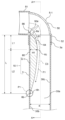
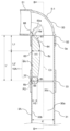
- FIG. 1 is a schematic diagram of a piping system 1 according to a first embodiment.
- the piping system 1 is used as a drainage system.
- the piping system 1 is a gutter system that receives rainwater from a roof 11a of a building 11 and drains it into a manhole 21 on the ground 20.
- the piping system 1 forms a flow path for rainwater.
- the rainwater collected in the manhole 21 flows out from the manhole 21 to a storm water pipe through a buried pipe 22.
- the building 11 is, for example, a non-residential facility such as a store, an office, a factory, a building, a school, a welfare facility, or a hospital, and a residential facility such as a detached house, an apartment building, or each dwelling unit of a detached house or an apartment building.
- the non-residential facility also includes a theater, a movie theater, a public hall, an amusement park, a complex, a department store, a hotel, an inn, a kindergarten, a library, a museum, an art museum, an underground shopping mall, a station, and an airport.
- the piping system 1 comprises an eaves gutter 2, a vertical pipe 3, a horizontal pipe 4, bent pipes 5-1 and 5-2, protruding members 6-1 and 6-2, a vertical pipe 7, and a drain 8.
- the eaves gutter 2 receives rainwater from the roof 11a of the building 11.
- the eaves gutter 2 is installed under the roof 11a of the building 11.
- the eaves gutter 2 is arranged at the eaves of the roof 11a.
- the eaves gutter 2 is arranged so as to extend along the eaves of the roof 11a.
- the eaves gutter 2 is in the shape of a long barrel.
- the eaves gutter 2 has a bottom wall 2a.
- a water collection port 2b is formed in the bottom wall 2a according to the overall design of the piping system 1.
- the water collection port 2b is, for example, a circular opening.
- the water collection port 2b is also called a drain or a drop port.
- the eaves gutter 2 may be formed by extrusion molding of a resin material.
- the eaves gutter 2 may include a core material for reinforcing the strength of the entire eaves gutter 2.
- the core material may be made of, for example, metal.
- the eaves gutter 2 may be formed of a metal plate, for example, a steel plate (also called a coil).
- the drain 8 is disposed at the water collection port 2b of the eaves gutter 2.
- the drain 8 reduces the generation of vortexes and the entrainment of air at the water collection port 2b.
- the drain 8 may contribute to the generation of the siphoning phenomenon.
- the drain 8 may be of a known configuration.
- the standpipe 3 defines a vertical flow path.
- the standpipe 3 is also called a downspout.
- the standpipe 3 is installed to drain rainwater from the water collection port 2b.
- the standpipe 3 allows rainwater from the water collection port 2b to flow vertically.
- the standpipe 3 is straight.
- the cross section perpendicular to the central axis C3 of the standpipe 3 is circular.
- the standpipe 3 is arranged so that the direction of the central axis C3 of the standpipe 3 coincides with the up-down direction (vertical direction).
- the standpipe 3 is fixed to the wall surface 11b of the building 11 by support brackets 35a, 35b, and 35c.
- the standpipe 3 has an upstream end 3a and a downstream end 3b.
- the upstream end 3a is the end of the standpipe 3 that is connected to the water collection port 2b (the upper end in FIG. 1).
- the downstream end 3b is the end of the standpipe 3 that is inserted into the manhole 21 (the lower end in FIG. 1).
- a drain pipe cover 34 is arranged to prevent rainwater from flowing into the manhole 21 through a gap between the standpipe 3 and the manhole 21.
- the material of the standpipe 3 is rigid polyvinyl chloride.
- the dimensions of the standpipe 3, for example, the outer shape and thickness, may be set in accordance with the standard for rigid polyvinyl chloride pipes (general) in JIS K 6741 "Rigid polyvinyl chloride pipes.”
- the building 11 has a relatively long eaves.
- the standpipe 3 were directly connected to the water collection port 2b, the distance between the standpipe 3 and the wall surface 11b of the building 11 would become too large, and the construction standards for the standpipe 3 may not be met.
- the standpipe 3 is not directly connected to the water collection port 2b, but is connected to the water collection port 2b via the horizontal pipe 4 and the bent pipes 5-1 and 5-2.
- the piping system 1 has a structure that is more suitable for a building 11 with long eaves.
- the horizontal pipe 4 defines a flow path that intersects the vertical direction.
- the horizontal pipe 4 is also called a call gutter.
- the horizontal pipe 4 is a part for flowing rainwater from the building 11 from the water collection port 2b to the vertical pipe 3.
- the horizontal pipe 4 is located between the rainwater collection port 2b from the building 11 and the vertical pipe 3.
- the horizontal pipe 4 is straight.
- the cross section perpendicular to the central axis C4 of the horizontal pipe 4 is circular.
- the horizontal pipe 4 is fixed so that the direction of the central axis C4 of the horizontal pipe 4 is inclined relative to the up-down direction (vertical direction).
- the horizontal pipe 4 has an upstream end 4a and a downstream end 4b.
- the upstream end 4a is the end of the horizontal pipe 4 that is connected to the water collection port 2b (the left end in FIG. 1).
- the downstream end 4b is the end of the horizontal pipe 4 that is connected to the vertical pipe 3 (the right end in FIG. 1).
- the material of the horizontal pipe 4 is rigid polyvinyl chloride.
- the dimensions of the horizontal pipe 4, for example, the outer diameter and thickness, may be set in accordance with the standard for rigid polyvinyl chloride pipes (general) in JIS K 6741 "Rigid polyvinyl chloride pipes.”
- the bent pipes 5-1 and 5-2 change the direction of the flow path.
- the bent pipes 5-1 and 5-2 are connection joints that connect flow paths with different directions, such as a vertical pipe and a horizontal pipe.
- Each of the bent pipes 5-1 and 5-2 has sockets 51 and 52 to which the upstream and downstream piping members are respectively connected, and a bent portion 50 that connects the sockets 51 and 52.
- the angle between the central axes of the sockets 51 and 52 is, for example, 91.17° as specified in JIS K 6739 "Rigid polyvinyl chloride pipe joints for drainage".
- the material of the bent pipes 5-1 and 5-2 is, for example, rigid polyvinyl chloride.
- bent pipes 5-1 and 5-2 may be set in accordance with the standard of JIS K 6739 "Rigid polyvinyl chloride pipe joints for drainage".
- the bent pipes 5-1 and 5-2 may be 90° bent elbows (so-called DLs) as specified in JIS K 6739.
- the bent pipe 5-1 is the first bent pipe that connects the vertical pipe 3 and the horizontal pipe 4.
- the bent pipe 5-1 connects the upstream end 3a of the vertical pipe 3 to the downstream end 4b of the horizontal pipe 4.
- the downstream end 4b of the horizontal pipe 4 is connected to the receiving port 51
- the upstream end 3a of the vertical pipe 3 is connected to the receiving port 52.
- the bent pipe 5-1 does not necessarily have to be a member that directly connects the upstream end 3a of the vertical pipe 3 to the downstream end 4b of the horizontal pipe 4, but may be a member that indirectly connects the upstream end 3a of the vertical pipe 3 to the downstream end 4b of the horizontal pipe 4 via another member.
- the bent pipe 5-2 is a second bent pipe that connects the water collection port 2b and the horizontal pipe 4.
- the bent pipe 5-2 connects the upstream end 4a of the horizontal pipe 4 to the water collection port 2b.
- the water collection port 2b is connected to the receiving port 51
- the upstream end 4a of the horizontal pipe 4 is connected to the receiving port 52.
- the bent pipe 5-2 does not necessarily have to be a member that directly connects the upstream end 4a of the horizontal pipe 4 to the water collection port 2b, but may be a member that indirectly connects the upstream end 4a of the horizontal pipe 4 to the water collection port 2b via another member.
- the standpipe 7 defines a vertical flow path.
- the standpipe 7 allows rainwater to flow vertically from the water collection port 2b.
- the standpipe 7 is connected to the drain 2c and is positioned downstream of the water collection port 2b.
- the standpipe 7 is between the water collection port 2b and the bent pipe 5-2.
- the standpipe 7 is straight.
- the cross section perpendicular to the central axis of the standpipe 7 is circular.
- the standpipe 7 is positioned so that the direction of the central axis of the standpipe 7 coincides with the up-down direction (vertical direction).
- the standpipe 7 has an upstream end 71 and a downstream end 72.
- the upstream end 71 is the end of the standpipe 7 that is connected to the water collection port 2b (the upper end in FIG. 1).
- the downstream end 72 is the end of the standpipe 7 that is connected to the receiving port 51 of the bent pipe 5-2 (the lower end in FIG. 1).
- the material of the standpipe 7 is rigid polyvinyl chloride.
- the dimensions of the standpipe 7, such as the outer diameter and thickness, may be set in accordance with the standard for rigid polyvinyl chloride pipes (general) in JIS K 6741 "Rigid polyvinyl chloride pipes.”
- the protrusion members 6-1 and 6-2 are disposed in a straight pipe disposed downstream of a bent pipe that changes the direction of the flow path, and are used to partially reduce the flow path cross-sectional area of the straight pipe.
- the vertical pipe 3 is a straight pipe disposed downstream of the bent pipe 5-1 that changes the direction of the flow path
- the horizontal pipe 4 is a straight pipe disposed downstream of the bent pipe 5-2 that changes the direction of the flow path.
- the protrusion member 6-1 is a first protrusion member that is disposed so that at least a portion of the vertical pipe 3 is a straight pipe.
- at least a portion of the vertical pipe 3 is the entire vertical pipe 3.
- the protrusion member 6-2 is a second protrusion member that is disposed so that at least a portion of the horizontal pipe 4 is a straight pipe.
- at least a portion of the horizontal pipe 4 is the entire horizontal pipe 4.
- the piping member 10-1 including the protrusion member 6-1 and the vertical pipe 3 is the first piping member
- the piping member 10-2 including the protrusion member 6-2 and the horizontal pipe 4 is the second piping member.
- the protrusion members 6-1 and 6-2 have the same configuration. Therefore, the piping members 10-1 and 10-2 have substantially the same configuration, although there is a difference between the vertical pipe 3 and the horizontal pipe 4. Below, the piping member 10-1 will be mainly described in detail. Those skilled in the art can easily understand that the explanation of the piping member 10-1 is also an explanation of the piping member 10-2 by replacing the description related to the vertical pipe 3 with the description related to the horizontal pipe 4.
- FIG. 2 is a perspective view of an example of the configuration of the piping member 10-1
- FIG. 3 is an exploded perspective view of the piping member 10-1.
- the piping member 10-1 includes a vertical pipe 3 and a protruding member 6-1.
- the protruding member 6-1 has a size, i.e., length, width, and height (thickness), that allows it to be placed inside the vertical pipe 3.
- the material of the protruding member 6-1 is, for example, rigid polyvinyl chloride.
- the protrusion member 6-1 has a first end 6a and a second end 6b.
- the first end 6a and the second end 6b are both ends in the longitudinal direction of the protrusion member 6-1.
- the longitudinal direction of the protrusion member 6-1 coincides with the direction of the central axis C3 of the vertical pipe 3.
- the first end 6a faces the upstream side, and the second end 6b faces the downstream side.
- a flow of fluid is generated from the first end 6a toward the second end 6b.
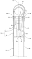
- FIG. 4 is a cross-sectional view of the piping member 10-1.
- FIG. 5 is an enlarged view of P1 in FIG. 4.
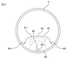
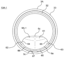
- FIG. 6 is a cross-sectional view taken along line A-A in FIG. 4.
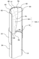
- FIG. 7 is a cross-sectional view of a portion of the piping member 10-1 cut away.
- FIG. 8 is a plan view of the piping member 10-1.
- FIG. 9 is a bottom view of the piping member 10-1.
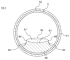
- FIG. 10 is a cross-sectional view taken along line IX-IX in FIG. 6.
- FIG. 11 is a cross-sectional view taken along line X-X in FIG. 6.
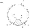
- FIG. 12 is a cross-sectional view taken along line XI-XI in FIG. 6.
- FIG. 13 is a cross-sectional view taken along line XII-XII in FIG. 6.
- FIG. 14 is a cross-sectional view taken along line XIII-XIII in FIG. 6.
- the protrusion member 6-1 has a contact surface 60 that contacts the inner circumferential surface 30a of the standpipe 3.
- the contact surface 60 has a convex shape when viewed from the direction of the central axis C3 of the standpipe 3.
- the radius of curvature of the contact surface 60 is set based on the radius of curvature of the inner circumferential surface 30a so that substantially no gap occurs between the contact surface 60 and the inner circumferential surface 30a of the standpipe 3.
- the protruding member 6-1 has a main surface 61 and first and second side surfaces 62, 63.
- the main surface 61 and the first and second side surfaces 62, 63 are on the opposite side of the protruding member 6-1 to the contact surface 60, and can come into contact with the fluid flowing in the vertical pipe 3.
- the main surface 61 extends from the first end 6a to the second end 6b.
- the main surface 61 faces the center of the vertical pipe 3 when viewed from the direction of the central axis C3 of the vertical pipe 3.
- the first side surface 62 and the second side surface 63 are on both sides of the main surface 61 when viewed from the direction of the central axis C3 of the vertical pipe 3.
- the first side surface 62 is on the left side of the main surface 61
- the second side surface 63 is on the right side of the main surface 61.
- the protrusion member 6-1 the main surface 61 and the first and second side surfaces 62, 63 can come into contact with the fluid flowing inside the vertical pipe 3. As shown in FIG. 6, the protrusion member 6-1 induces a flow F1 along the main surface 61, a flow F2 along the first side surface 62, and a flow F3 along the second side surface 63. Because the main surface 61 and the first and second side surfaces 62, 63 can come into contact with the fluid, it is preferable that the surface roughness of the main surface 61 and the first and second side surfaces 62, 63 be small, as this is expected to improve the flow rate.
- the protrusion member 6-1 has a first separation wall 64 for promoting separation of the flow F1 and the flow F2.
- the presence of the first separation wall 64 can make it easier for the flow F2 to separate from the flow F1.
- the first separation wall 64 is between the main surface 61 and the first side surface 62.
- the first separation wall 64 is the boundary portion between the main surface 61 and the first side surface 62.
- the boundary portion between the main surface 61 and the first side surface 62 constitutes a wall between a flow path having the main surface 61 as its bottom surface and a flow path having the first side surface 62 as its bottom surface.
- the first separation wall 64 can be formed by having both the main surface 61 and the first side surface 62 have a concave shape.
- the protrusion member 6-1 has a second separation wall 65 to promote separation of the flow F1 and the flow F3.
- the presence of the second separation wall 65 can make it easier for the flow F3 to separate from the flow F1.
- the second separation wall 65 is between the main surface 61 and the second side surface 63.
- the second separation wall 65 is the boundary portion between the main surface 61 and the second side surface 63.
- the boundary portion between the main surface 61 and the second side surface 63 constitutes a wall between a flow path having the main surface 61 as its bottom surface and a flow path having the second side surface 63 as its bottom surface.
- the second separation wall 65 can be formed by having both the main surface 61 and the second side surface 63 have a concave shape.
- the shape (cross-sectional shape) of the protrusion member 6-1 when viewed from the direction of the central axis C3 of the vertical pipe 3 changes along the direction of the central axis C3 of the vertical pipe 3.
- the height of the protruding member 6-1 changes along the direction of the central axis C3 of the vertical pipe 3.
- the protruding member 6-1 has a top portion 6c and a protruding portion 6h.
- the top 6c is between the first end 6a and the second end 6b.
- the top 6c is the highest part of the protruding member 6-1.
- the top 6c makes the flow path cross-sectional area of the vertical pipe 3 the smallest.
- the protrusion 6h extends from the area between the top 6c and the second end 6b toward the center of the vertical pipe 3 when viewed from the direction of the central axis C3 of the vertical pipe 3. In this embodiment, the protrusion 6h is at the second end 6b. The protrusion 6h does not protrude beyond the top 6c when viewed from the direction of the central axis C3 of the vertical pipe 3.
- the height of the protruding member 6-1 increases monotonically from the first end 6a toward the apex 6c.
- the height of the protruding member 6-1 decreases monotonically from the apex 6c toward the second end 6b.
- the height of the protruding member 6-1 decreases from the apex 6c to the protruding portion 6h, and then increases or decreases in accordance with the shape of the protruding portion 6h.
- the second end 6b has a tapered shape when viewed in the width direction of the protruding member 6-1.
- the height of the protruding member 6-1 becomes 0 at the second end 6b.
- the main surface 61 includes a curved shape that protrudes toward the second wall surface 30c at the apex 6c. This improves the flow rate. From another perspective, the main surface 61 only needs to have a shape that protrudes toward the second wall surface 30c so as to produce the Coanda effect on the downstream side of the bent pipe 5-1. In other words, the main surface 61 only needs to have a shape that produces the Coanda effect on the downstream side of the bent pipe 5-1. This improves the flow rate while allowing for miniaturization.
- the shape of the protruding member 6-1 when the height of the protruding member 6-1 decreases monotonically from the apex 6c toward the second end 6b (hereinafter referred to as the basic shape) is shown by a two-dot chain line.
- the dimensions a and b of the protruding portion 6h can be set based on this basic shape.
- the second end 6b is tapered when viewed in the width direction of the protruding member 6-1.
- the height of the protruding member 6-1 becomes 0.
- Dimension a may be the maximum amount of protrusion from the basic shape.
- Dimension b may be the distance between the upstream and downstream boundaries of the basic shape and the protruding portion 6h.
- the protruding portion 6h includes a curved shape that protrudes toward the second wall surface 30c. This can improve the flow rate.
- the protruding portion 6h may have a shape that protrudes toward the second wall surface 30c so as to generate the Coanda effect.
- the protruding portion 6h may have a shape that generates the Coanda effect downstream of the apex 6c. This can improve the flow rate.
- the radius of curvature of the upstream corner 6h1 and the downstream corner 6h2 of the protruding portion 6h viewed from the width direction of the protruding member 6-1 is r, then r ⁇ a or r ⁇ b. Preferably, r ⁇ a and r ⁇ b.
- the upstream corner 6h1 and the downstream corner 6h2 may have different radii of curvature.
- the protrusion 6h is located at the second end 6b.
- the protrusion 6h is formed across the entire width of the second end 6b.
- the protrusion 6h when viewed from the direction of the central axis C3 of the vertical pipe 3, at least a portion of the protrusion 6h has a convex shape. This can contribute to reducing pressure loss in the protrusion member 6-1.
- the protruding member 6-1 induces a flow F1 along the protruding member 6-1, mainly along the main surface 61.
- the protruding member 6-1 has a protruding portion 6h at a portion between the apex 6c and the second end 6b.
- a flow F4 can be generated along the protruding portion 6h downstream of the flow F1.
- the path of the flow F1 can be extended compared to when the protruding portion 6h does not exist. This promotes the Coanda effect by the protruding member 6-1, and the flow rate can be improved.
- the protruding portion 6h itself induces the Coanda effect, making it easier to induce flow F4.
- the main surface 61 when viewed from the direction of the central axis C3 of the vertical pipe 3, at least a portion of the main surface 61 is concave. At least a portion of the main surface 61 is the portion of the main surface 61 on the first end 6a side. In other words, the main surface 61 is concave at the first end 6a.
- the radius of curvature of at least a portion of the main surface 61 (first end 6a) is equal to or less than the radius of curvature of the inner surface 30a of the vertical pipe 3. This reduces pressure loss in the protruding member 6-1.
- the main surface 61 is concave at the first end 6a, but convex at the second end 6b, as shown in Figs. 8 to 12. That is, the shape of the main surface 61 as viewed from the direction of the central axis C3 of the vertical pipe 3 changes from concave to convex from the first end 6a to the second end 6b. This makes it easier for a flow to occur along the main surface 61 of the protruding member 6-1. In this embodiment, as shown in Fig. 12, the shape of the main surface 61 as viewed from the direction of the central axis C3 of the vertical pipe 3 is convex at the top 6c.
- the shape of the main surface 61 as viewed from the direction of the central axis C3 of the vertical pipe 3 is convex in the range from the top 6c to the second end 6b.
- the protruding member 6-1 has a flat portion 6d between the first end 6a and the top 6c. As shown in Fig. 11, at the flat portion 6d, the main surface 61 is flat when viewed from the direction of the central axis C3 of the vertical pipe 3.
- the center of the concave shape of the principal surface 61 In the range where the principal surface 61 has a concave shape, the center of the concave shape of the principal surface 61, i.e., the lowest part of the concave shape, is located closer to the center in the width direction of the protrusion member 6-1 than the ends. In the range where the principal surface 61 has a convex shape, the center of the convex shape of the principal surface 61, i.e., the highest part of the convex shape, is located closer to the center in the width direction of the protrusion member 6-1 than the ends. In this embodiment, the center of the convex shape of the principal surface 61 coincides with the center in the width direction of the protrusion member 6-1.
- the shapes of the first side surface 62 and the second side surface 63 when viewed from the direction of the central axis C3 of the vertical pipe 3 change along the direction of the central axis C3 of the vertical pipe 3.
- the first side surface 62 when viewed from the direction of the central axis C3 of the vertical pipe 3, at least a portion of the first side surface 62 is concave. At least a portion of the first side surface 62 is the portion of the first side surface 62 on the first end 6a side. In other words, the first side surface 62 is concave at the first end 6a. This reduces pressure loss at the protruding member 6-1.
- the second side surface 63 when viewed from the direction of the central axis C3 of the vertical pipe 3, at least a portion of the second side surface 63 is concave. At least a portion of the second side surface 63 is the portion of the second side surface 63 on the first end 6a side. In other words, the second side surface 63 is concave at the first end 6a. This reduces pressure loss at the protruding member 6-1.
- the shape of the first side surface 62 When viewed from the direction of the central axis C3 of the vertical pipe 3, the shape of the first side surface 62 remains concave from the first end 6a to the second end 6b. As can be seen from Figures 12 to 14, the depth of the concave shape of the first side surface 62 becomes shallower as it moves from the top 6c to the second end 6b. This allows the flow F2 along the first side surface 62 to smoothly merge with the flow F1 along the main surface 61 downstream of the protruding member 6-1.
- the shape of the second side surface 63 When viewed from the direction of the central axis C3 of the vertical pipe 3, the shape of the second side surface 63 remains concave from the first end 6a to the second end 6b. As can be seen from Figures 12 to 14, the depth of the concave shape of the second side surface 63 becomes shallower from the top 6c to the second end 6b. This allows the flow F3 along the second side surface 63 to smoothly merge with the flow F1 along the main surface 61 downstream of the protruding member 6-1.
- the first side surface 62 and the second side surface 63 are symmetrical with respect to the center line of the protrusion member 6-1 that is aligned with the central axis C3 of the vertical pipe 3. This improves the flow rate.
- the width of the protruding member 6-1 changes along the direction of the central axis C3 of the upright pipe 3.
- the width of the protruding member 6-1 refers to the width at the portion of the protruding member 6-1 closest to the inner peripheral surface 30a of the upright pipe 3.
- the width of the protruding member 6-1 corresponds to the width of the contact surface 60 of the protruding member 6-1.
- the protruding member 6-1 has a first portion 6e, a second portion 6f, and a third portion 6g between the first end 6a and the second end 6b, where the direction of the change in width changes.
- the first portion 6e is between the first end 6a and the apex 6c, more specifically, the flat portion 6d.
- the second portion 6f is between the apex 6c and the second end 6b.
- the third portion 6g is between the second portion 6f and the second end 6b.
- the width of the protruding member 6-1 increases monotonically from the first end 6a to the first portion 6e.
- the width of the protruding member 6-1 monotonically decreases from the first portion 6e to the second portion 6f.
- the width of the protruding member 6-1 monotonically increases from the second portion 6f to the third portion 6g.
- the width of the protruding member 6-1 monotonically decreases from the third portion 6g to the second end 6b.
- the width of the protruding member 6-1 is largest at the first portion 6e.
- the maximum value of the width of the protruding member 6-1 as viewed from the direction of the central axis C3 of the vertical pipe 3 (the width at the first portion 6e) is W1. If the inner diameter of the vertical pipe 3 is d, then 0.5d ⁇ W1 ⁇ 0.9d.
- W2 the maximum value of the distance between the first partition wall 64 and the second partition wall 65 as viewed from the direction of the central axis C3 of the vertical pipe 3 is W2, then 0.3d ⁇ W2 ⁇ 0.7d. W2 ⁇ W1.
- the width of the main surface 61 narrows from the first end 6a to the second end 6b, at least from the first end 6a to the apex 6c. This configuration allows the flows F2, F3 along the first side surface 62 and the second side surface 63 to smoothly merge with the flow F1 along the main surface 61 downstream of the protruding member 6-1. In this embodiment, the width of the main surface 61 decreases monotonically from the first end 6a to the second end 6b.
- the first side 62 includes a portion that becomes wider from the first end 6a toward the second end 6b. More specifically, the portion of the first side 62 on the first end 6a side becomes wider from the first end 6a toward the second end 6b. This configuration can reduce pressure loss. In this embodiment, the portion of the first side 62 on the first end 6a side includes the portion of the first side 62 from the first end 6a to the flat portion 6d.
- the second side 63 includes a portion that becomes wider from the first end 6a toward the second end 6b. More specifically, the portion of the second side 63 on the first end 6a side becomes wider from the first end 6a toward the second end 6b. This configuration can reduce pressure loss. In this embodiment, the portion of the second side 63 on the first end 6a side includes the portion of the second side 63 from the first end 6a to the flat portion 6d.
- the first separation wall 64 and the second separation wall 65 are formed on a part of the protrusion member 6-1, not on the entirety, in the direction of the central axis C3 of the vertical pipe 3. More specifically, the first separation wall 64 and the second separation wall 65 exist in a predetermined range from the first end 6a along the direction of the central axis C3 of the vertical pipe 3.
- the predetermined range is the range from the first end 6a to the flat portion 6d.
- the distance between the first separation wall 64 and the second separation wall 65 becomes shorter from the first end 6a toward the second end 6b.
- This configuration separates the flows F2, F3 along the first side surface 62 and the second side surface 63 from the flow F1 along the main surface 61 on the upstream side of the protruding member 6-1, and allows the flows F2, F3 along the first side surface 62 and the second side surface 63 to smoothly merge with the flow F1 along the main surface 61 on the downstream side of the protruding member 6-1.
- the heights of the first separation wall 64 and the second separation wall 65 decrease from the first end 6a toward the second end 6b. This configuration separates the flows F2 and F3 along the first and second sides 62 and 63 from the flow F1 along the main surface 61 on the upstream side of the protruding member 6-1, and allows the flows F2 and F3 along the first and second sides 62 and 63 to smoothly merge with the flow F1 along the main surface 61 on the downstream side of the protruding member 6-1.
- d be the diameter of the vertical tube 3
- L be the distance between the first end 6a and the second end 6b in the direction of the central axis C3 of the vertical tube 3 (i.e., the length of the protrusion member 6-1).
- 0.5d ⁇ L ⁇ 5.0d it is preferable that 0.5d ⁇ L ⁇ 5.0d. This can further reduce the occurrence of pressure loss due to separation downstream from the bent tube 5-1. Therefore, the flow rate can be improved while enabling miniaturization.
- the top 6c of the protrusion member 6-1 is the portion of the piping member 10-1 where the flow path cross-sectional area is the smallest.
- the distance between the first end 6a and the top 6c in the direction of the central axis C3 of the vertical pipe 3 is L1. It is preferable that 0.1L ⁇ L1 ⁇ 0.5L be satisfied for the protrusion member 6-1. This can further reduce the occurrence of pressure loss caused by separation downstream from the bent pipe 5-1. This can improve the flow rate while enabling miniaturization.
- the distance between the top 6c and the second end 6b in the direction of the central axis C3 of the vertical pipe 3 is L2.
- L2 L - L1. It is preferable that L2 > L1 in the protruding member 6-1. This can further reduce the occurrence of pressure loss caused by separation downstream from the bent pipe 5-1. Therefore, the flow rate can be improved while enabling miniaturization.
- the distance between the top 6c of the protruding member 6-1 and the second wall surface 30c is defined as D1. It is preferable that 0.60d ⁇ D1 ⁇ 0.95d be satisfied for the protruding member 6-1. This can further reduce the occurrence of pressure loss caused by separation downstream from the bent pipe 5-1. Therefore, the flow rate can be improved while enabling miniaturization.
- the height of the top 6c of the protruding member 6-1 is defined as H1.
- H1 is equal to d-D1. It is preferable that 0.05d ⁇ H1 ⁇ 0.40d is satisfied for the protruding member 6-1. This can further reduce the occurrence of pressure loss caused by separation downstream from the bent pipe 5-1. Therefore, the flow rate can be improved while enabling miniaturization.
- the maximum flow path cross-sectional area of the vertical pipe 3 is A.
- the cross-sectional area of the protruding member at the top 6c is A1.
- A1/A ⁇ 0.4 In the protruding member 6-1, it is preferable that A1/A ⁇ 0.4. This can further reduce the occurrence of pressure loss caused by separation downstream from the bent pipe 5-1. Therefore, the flow rate can be improved while enabling miniaturization.
- the minimum value of the flow path cross-sectional area of the piping member 10-1 is A2.
- the protrusion member 6-1 has a contact end surface 66 at the first end 6a.
- the inner diameter of the vertical pipe 3 is larger than the inner diameter of the bent portion 50 of the bent pipe 5-1.
- the contact end surface 66 is provided to fill the difference in inner diameter between the vertical pipe 3 and the bent portion 50 of the bent pipe 5-1.
- the presence of the contact end surface 66 can reduce the step between the inner wall surface 50a of the bent portion 50 of the bent pipe 5-1 and the main surface 61 of the protrusion member 6-1. This makes it less likely that the flow of fluid from the bent pipe 5-1 to the piping member 10-1 will be obstructed.
- the protrusion member 6-1 has a protrusion 67.
- the protrusion 67 is used to join or position the upright pipe 3 and the protrusion member 6-1.
- the protrusion 67 is disposed on the contact surface 60.
- the protrusion 67 is shaped to fit into the recess 3c of the upright pipe 3.
- the upright pipe 3 has a pair of recesses 3c on the edge of the upstream end 3a.
- the recesses 3c are formed as notches.
- the protrusion member 6-1 has a pair of protrusions 67 that fit into the pair of recesses 3c, respectively.
- the protrusion member 6-1 is positioned relative to the upright pipe 3 by fitting the pair of protrusions 67 into the pair of recesses 3c, respectively.
- the protruding member 6-1 is disposed on the inner peripheral surface 30a of the standpipe 3.
- the flow path cross-sectional area of the piping member 10-1 is not constant, and there is a reduced portion where the flow path cross-sectional area of the piping member 10-1 is smaller than the cross-sectional area of the standpipe 3.
- the protruding member 6-1 is located closer to the upstream end 3a of the standpipe 3 than the downstream end 3b of the standpipe 3.
- the protruding member 6-1 is located at the upstream end 3a of the standpipe 3. In other words, the protruding member 6-1 reduces the flow path at the upstream end 3a of the standpipe 3 that connects to the bent pipe 5-1.
- the protruding member 6-1 is arranged to protrude from a first wall surface 30b on the inner periphery of the vertical pipe 3 toward a second wall surface 30c on the outer periphery of the vertical pipe 3.
- the first wall surface 30b is a portion of the inner periphery of the bent pipe 5-1 on the inner periphery of the vertical pipe 3 (for example, half of the inner periphery).
- the second wall surface 30c is a portion of the inner periphery of the bent pipe 5-1 on the inner periphery of the vertical pipe 3 (for example, half of the outer periphery).
- the inner periphery of the vertical pipe 3 is composed of the first wall surface 30b and the second wall surface 30c.
- the protruding member 6-1 is placed inside the vertical pipe 3, which is located downstream of the bent pipe 5-1.
- the bent pipe 5-1 directs water that has flowed in from the horizontal pipe 4 into the vertical pipe 3. If the direction of the water flow changes significantly in the bent pipe 5-1, pressure loss due to separation can be one of the factors that reduces the flow rate.
- FIG. 15 is a diagram of a simulation of pressure distribution in the piping member 100 of the comparative example.
- the piping member 100 of the comparative example differs from the piping member 10-1 in that it does not have the protrusion member 6-1.
- the darker the color the lower the pressure.
- the pressure loss is large at the portion indicated by R in FIG. 15, and the presence of such a portion with large pressure loss can be a major factor in the decrease in flow rate.
- the pressure loss at the portion indicated by R in FIG. 15 is thought to be caused by peeling. This peeling is caused by water separating from the first wall surface 30b of the piping member 100 downstream of the inner wall surface 50a of the bent pipe 5-1. In other words, as shown by the arrow F in FIG.
- the water flowing in from the upstream side initially flows along the pipe wall 200, but after the inner wall surface 50a of the bent pipe 5-1, it may separate from the first wall surface 30b of the piping member 100. Such peeling is particularly likely to be noticeable when the water flow speed is high. The faster the flow velocity, the greater the area where pressure loss occurs.
- the piping member 10-1 has a protruding member 6-1.
- the presence of the protruding member 6-1 is expected to (1) make it easier for water to flow along the pipe wall than when the protruding member 6-1 is not present, and (2) reduce the number of areas where pressure loss may occur. Therefore, the protruding member 6-1 can reduce the occurrence of pressure loss due to separation downstream from the bent pipe 5-1, and improve the flow rate.
- the piping member 10-1 can be made smaller by simply providing the protruding member 6-1, since it is not necessary to increase the radius of curvature of the inner surface on the inner side of the bent pipe 5-1.
- the protruding member 6-1 can improve the flow rate while making it possible to make the system smaller.
- the protruding member 6-1 is inside the vertical pipe 3, and the protruding member 6-1 is not noticeable when viewed as the piping system 1 as a whole. This is expected to improve the aesthetic appearance of the piping system 1 as a whole.
- the protruding member 6-1 has a protruding portion 6h in the area between the top 6c and the second end 6b.
- the path of the flow (mainly flow F1) along the protruding member 6-1 can be extended. This promotes the Coanda effect of the protruding member 6-1, and the flow rate can be improved.
- the presence of the protruding portion 6h makes it possible to improve the strength of the area between the top 6c and the second end 6b of the protruding member 6-1.
- the above-mentioned protruding members 6-1 and 6-2 are arranged in the straight pipes (vertical pipe 3, horizontal pipe 4) arranged downstream of the bent pipes 5-1 and 5-2 that change the direction of the flow path, and partially reduce the flow path cross-sectional area of the straight pipes.
- the protruding members 6-1 and 6-2 are provided with a top portion 6c that is located between a first end 6a facing the upstream side and a second end 6b facing the downstream side and that minimizes the flow path cross-sectional area of the straight pipes (vertical pipe 3, horizontal pipe 4), and a protruding portion 6h that extends from a portion between the top portion 6c and the second end 6b toward the center of the straight pipes (vertical pipe 3, horizontal pipe 4) when viewed from the direction of the central axes C3 and C4 of the straight pipes (vertical pipe 3, horizontal pipe 4), but does not protrude beyond the top portion 6c.
- This configuration can improve the flow rate while enabling miniaturization.
- the protruding portion 6h is located at the second end 6b. This configuration reduces pressure loss in the protruding members 6-1 and 6-2. This configuration can reduce the possibility of damage to the second ends 6b of the protruding members 6-1 and 6-2.
- the protruding members 6-1 and 6-2 if the dimension of the protruding portion 6h as viewed from the direction of the central axes C3 and C4 of the straight pipes (vertical pipe 3 and horizontal pipe 4) is a and the inner diameter of the straight pipes (vertical pipe 3 and horizontal pipe 4) is d, then 0.01d ⁇ a ⁇ 0.05d is satisfied. This configuration can improve the flow rate.
- the protruding members 6-1 and 6-2 if the dimension of the protruding portion 6h in the direction of the central axes C3 and C4 of the straight pipes (vertical pipe 3 and horizontal pipe 4) is b and the inner diameter of the straight pipes (vertical pipe 3 and horizontal pipe 4) is d, then 0.01d ⁇ b ⁇ 0.05d is satisfied. This configuration can improve the flow rate.
- the protruding members 6-1 and 6-2 if the maximum flow area of the straight pipes (vertical pipe 3 and horizontal pipe 4) is A and the cross-sectional area of the protruding members 6-1 and 6-2 at the top 6c is A1, then A1/A ⁇ 0.4. This configuration can improve the flow rate.
- the second ends 6b are tapered when viewed in the width direction of the protruding members 6-1 and 6-2. This configuration can reduce pressure loss between the second ends 6b and the inner circumferential surfaces 30a of the straight pipes (the vertical pipes 3 and the horizontal pipes 4). The flow rate can be improved.
- the piping members 10-1 and 10-2 described above include protruding members 6-1 and 6-2 and straight pipes (vertical pipe 3 and horizontal pipe 4). This configuration can improve the flow rate while enabling miniaturization.
- the piping system 1 described above comprises a vertical pipe 3 fixed to the wall surface 11b of the building 11, a horizontal pipe 4 located between the vertical pipe 3 and the rainwater collection port 2b from the building 11, a first bent pipe 5-1 located between the horizontal pipe 4 and the vertical pipe 3, a second bent pipe 5-2 located between the water collection port 2b and the horizontal pipe 4, and protruding members 6-1 and 6-2.
- the protruding member 6-1 is arranged such that at least a portion of the vertical pipe 3 is a straight pipe
- the protruding member 6-2 is arranged such that at least a portion of the horizontal pipe 4 is a straight pipe. This configuration can improve the flow rate while enabling miniaturization.
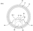
- Second embodiment 1.2.1 Configuration 16 is a schematic diagram of a piping system 1A according to embodiment 2.
- the piping system 1A includes an eaves gutter 2, a vertical pipe 3A, a horizontal pipe 4A, bent pipes 5-1 and 5-2, protruding members 6A-1 and 6A-2, a vertical pipe 7, and a drain 8.
- the vertical pipe 3A is composed of multiple piping components.
- the vertical pipe 3A includes straight pipes 31, 32 and a connection joint 33 that connects the straight pipes 31, 32 to each other.
- the vertical pipe 3A is composed of multiple piping components.
- the vertical pipe 3A includes straight pipes 31, 32 and a connection joint 33 that connects the straight pipes 31, 32 to each other.
- the straight pipe 31 is the downstream portion of the vertical pipe A, and the straight pipe 32 is the upstream portion of the vertical pipe 3A. In this embodiment, the straight pipe 31 is longer than the straight pipe 32.
- the first end (upper end in FIG. 16) of the straight pipe 32 defines the upstream end 3a of the vertical pipe 3A, the second end (lower end in FIG. 15) of the straight pipe 32 is connected to the first end (upper end in FIG.
- the material of the straight pipes 31, 32 and the connecting joint 33 is rigid polyvinyl chloride.
- the dimensions of the straight pipes 31, 32, for example, the outer shape and thickness, may be set in accordance with the standard for rigid polyvinyl chloride pipes (general) of JIS K 6741 "Rigid polyvinyl chloride pipes”.
- the dimensions of the connecting joint 33, for example, the outer shape and thickness, may be set in accordance with the standard for sockets of JIS K 6739 "Rigid polyvinyl chloride pipe joints for drainage".
- the horizontal pipe 4A is composed of multiple piping components.
- the horizontal pipe 4A includes straight pipes 41 and 42 and a connecting joint 43 that connects the straight pipes 41 and 42 together.
- the straight pipe 41 is the downstream portion of the horizontal pipe 4A, and the straight pipe 42 is the upstream portion of the horizontal pipe A. In this embodiment, the straight pipe 41 is longer than the straight pipe 42.
- the first end (left end in FIG. 16) of the straight pipe 42 defines the upstream end 4a of the horizontal pipe 4A
- the second end (right end in FIG. 16) of the straight pipe 42 is connected to the first end (left end in FIG. 16) of the straight pipe 41 via the connecting joint 43
- the second end (right end in FIG. 16) of the straight pipe 41 defines the downstream end 4b of the horizontal pipe 4A.
- the material of the straight pipes 41 and 42 and the connecting joint 43 is rigid polyvinyl chloride.
- the dimensions of the straight pipes 41, 42, for example, the outer shape and thickness, may be set in accordance with the standard for rigid polyvinyl chloride pipes (general) in JIS K 6741 "Rigid polyvinyl chloride pipes.”
- the dimensions of the connection fitting 43, for example, the outer shape and thickness, may be set in accordance with the standard for sockets in JIS K 6739 "Rigid polyvinyl chloride pipe fittings for drainage.”
- the protrusion members 6A-1 and 6A-2 are disposed in a straight pipe that is disposed downstream of a bent pipe that changes the direction of the flow path, and are used to partially reduce the flow path cross-sectional area of the straight pipe.
- the straight pipe 32 of the vertical pipe 3A is disposed downstream of the bent pipe 5-1 that changes the direction of the flow path
- the straight pipe 42 of the horizontal pipe 4A is disposed downstream of the bent pipe 5-2 that changes the direction of the flow path.
- the protrusion member 6A-1 is a first protrusion member that is disposed so that at least a portion of the vertical pipe 3A is a straight pipe.
- at least a portion of the vertical pipe 3A is a straight pipe 32.
- the protrusion member 6A-2 is a second protrusion member that is disposed so that at least a portion of the horizontal pipe 4A is a straight pipe.
- at least a portion of the horizontal pipe 4A is a straight pipe 42.
- the piping member 10A-1 including the protrusion member 6A-1 and the straight pipe 32 is the first piping member.
- the piping member 10A-2 including the protrusion member 6A-2 and the straight pipe 42 is the second piping member.
- the piping member 10A-1 is made up of only a part of the vertical pipe 3A (straight pipe 32), and is therefore easier to transport than the piping member 10-1.
- the protrusion members 6A-1 and 6A-2 have the same configuration. Therefore, the piping members 10A-1 and 10A-2 have substantially the same configuration, although there is a difference between the straight pipe 32 of the vertical pipe 3A and the straight pipe 42 of the horizontal pipe 4A.
- the piping member 10A-1 will be mainly described in detail. Those skilled in the art can easily understand that the explanation of the piping member 10A-1 is also an explanation of the piping member 10A-2 by replacing the description related to the vertical pipe 3A with the description related to the horizontal pipe 4A.
- FIG. 17 is a perspective view of an example configuration of the piping member 10A-1
- FIG. 18 is an exploded perspective view of the piping member 10A-1.
- the piping member 10A-1 comprises a straight pipe 32 of the vertical pipe 3A and a protruding member 6A-1.
- the protruding member 6A-1 has a size, i.e., length, width, and height (thickness), that allows it to be placed inside the straight pipe 32 of the vertical pipe 3A.
- the material of the protruding member 6A-1 is, for example, rigid polyvinyl chloride.
- the protrusion member 6A-1 has a first end 6a and a second end 6b.
- the first end 6a and the second end 6b are both ends in the longitudinal direction of the protrusion member 6A-1.
- the longitudinal direction of the protrusion member 6A-1 coincides with the direction of the central axis C3 of the vertical pipe 3A.
- the first end 6a faces the upstream side, and the second end 6b faces the downstream side.
- a flow of fluid is generated from the first end 6a toward the second end 6b.
- Figure 19 is a cross-sectional view of the piping member 10A-1.
- Figure 20 is an enlarged view of P2 in Figure 19.
- Figure 21 is a cross-sectional view taken along line B-B in Figure 19.
- Figure 22 is a cross-sectional view of a portion of the piping member 10A-1 cut away.
- Figure 23 is a plan view of the piping member 10A-1.
- Figure 24 is a bottom view of the piping member 10A-1.
- the protrusion member 6A-1 has the same shape as the protrusion member 6-1 on the first end 6a side. However, unlike the protrusion member 6-1, the protrusion member 6A-1 has an end face 68 on the second end 6b. The end face 68 intersects with the central axis C3 of the vertical pipe 3A. In this embodiment, the end face 68 is perpendicular to the central axis C3 of the vertical pipe 3A.
- the protruding member 6A-1 has a top 6c and a protruding portion 6h.
- the protruding portion 6h extends from the portion between the top 6c and the second end 6b toward the center of the upright pipe 3 when viewed from the direction of the central axis C3 of the upright pipe 3. In this embodiment, the protruding portion 6h is located at the second end 6b.
- the shape of the protrusion member 6-1A when the height of the protrusion member 6-1A decreases monotonically from the top 6c toward the second end 6b (hereinafter referred to as the basic shape) is shown by a two-dot chain line.
- the dimensions a and b of the protrusion 6h can be set based on this basic shape.
- Dimension a may be the maximum amount of protrusion from the basic shape.
- Dimension b may be the distance between the upstream and downstream boundaries of the basic shape and the protrusion 6h.
- the protruding member 6A-1 fits within the straight pipe 32 in the direction of the central axis C3 of the vertical pipe 3A.
- the length of the protruding member 6A-1 (the distance between the first end 6a and the second end 6b) is equal to the length of the straight pipe 32. That is, in the piping member 10A-1, the entire protruding member 6A-1 is within the straight pipe 32. This allows the protruding member 6A-1 to be protected by the straight pipe 32 compared to a case in which the protruding member 6A-1 is partially protruding from the straight pipe 32. This reduces the possibility of damage to the protruding member 6A-1.
- FIG. 25 is a comparison diagram between the protrusion member 6A-1 according to the second embodiment and the protrusion member 6-1 according to the first embodiment. From FIG. 25, it can be said that the protrusion member 6A-1 has a shape in which the portion on the second end 6b side of the protrusion member 6-1 is cut in a direction perpendicular to the central axis C3 of the vertical pipe 3A. However, in the protrusion member 6A-1, the protrusion 6h is also between the top 6c and the second end 6b. The height of the protrusion member 6A-1 monotonically decreases from the top 6c to the protrusion 6h.
- the protrusion member 6A-1 virtually has a portion where the height of the protrusion member 6A-1 becomes 0.
- the portion where the height of the protrusion member 6A-1 becomes 0 may correspond to the second end 6b of the protrusion member 6-1.
- the protruding member 6A-1 can be made smaller in dimension in the direction of the central axis C3 of the vertical pipe 3A than the protruding member 6-1.
- the protruding member 6A-1 has a shape in which the portion of the protruding member 6-1 on the second end 6b side that protrudes from the straight pipe 32 to the outside has been cut.
- the portion of the protruding member 6-1 on the second end 6b side protrudes outward from the second end of the straight pipe 32.
- the second end 6b of the protruding member 6-1 is thin and therefore easily damaged.
- the protruding member 6-1 when the protruding member 6-1 is placed in the straight pipe 32, there is a possibility that the protruding member 6-1 will be damaged during transportation, etc. In contrast, the entire protruding member 6A-1 is inside the straight pipe 32, so the possibility of damage to the protruding member 6A-1 can be reduced.
- the protrusion member 6A-1 has the advantage that the dimension in the direction of the central axis C3 of the vertical pipe 3A can be made smaller than that of the protrusion member 6-1, and damage can be prevented. Such a change in shape between the protrusion member 6A-1 and the protrusion member 6-1 can also cause a change in pressure loss. Therefore, the change in pressure loss caused by the difference in shape between the protrusion member 6-1 and the protrusion member 6A-1 was evaluated.
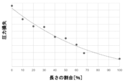
- Figure 26 is a graph showing the change in pressure loss due to the protrusion member 6A-1 compared to the protrusion member 6-1.
- the vertical axis indicates pressure loss in the piping member.
- the horizontal axis indicates the length percentage [%].
- the length percentage [%] is the percentage of the distance from the apex 6c to the second end 6b of the protruding member 6A-1 relative to the distance from the apex 6c to the second end 6b of the protruding member 6-1.
- a length ratio of 100% indicates that the shape of the protrusion member 6A-1 is equal to the shape of the protrusion member 6-1.
- a length ratio of 0% indicates that the shape of the protrusion member 6A-1 is from the first end 6a to the apex 6c.
- the height of the protrusion member 6A-1 decreases monotonically from the apex 6c to the second end 6b. Therefore, the height of the protrusion member 6A-1 at the second end 6b increases as the length ratio decreases. From FIG. 26, it can be seen that the effect of reducing pressure loss decreases as the length ratio decreases. However, the relationship between the length ratio and the pressure loss is not linear, and the pressure loss increases exponentially with the decrease in the length ratio.
- L2' is set to satisfy the following condition. That is, if the height of the protruding member 6A-1 at the top 6c is H1 and the height of the protruding member 6A-1 at the second end 6b is H2, then 0.05H1 ⁇ H2 ⁇ 0.90H1. This allows for miniaturization while improving the flow rate.
- the length of the protruding member 6A-1 can be made shorter than that of the protruding member 6-1. This allows for miniaturization of the protruding member 6A-1.
- the protruding member 6A-1 has fewer thin areas downstream of the protruding member 6A-1, which may reduce the possibility of damage to the protruding member 6A-1.
- the formula 0.5d ⁇ L ⁇ 5.0d can be rewritten as 0.5d ⁇ L1+H1/(H1-H2) ⁇ L2' ⁇ 5.0d using L1 and L2'. Therefore, in the protruding member 6A-1, if the inner diameter of the straight pipe 32 is d, the distance between the first end 6a and the apex 6c in the direction of the central axis C3 of the straight pipe 32 is L1, and the distance between the apex 6c and the second end 6b in the direction of the central axis C3 of the straight pipe 32 is L2', then it is preferable that 0.5d ⁇ L1+H1/(H1-H2) ⁇ L2' ⁇ 5.0d.
- the above-described protruding members 6A-1, 6A-2 have, at the second ends 6b, end faces 68 that intersect with the central axes C3, C4 of the straight pipes 32, 42.
- This configuration can improve the flow rate while enabling miniaturization.
- This configuration can reduce the possibility of breakage at the second ends 6b of the protruding members 6A-1, 6A-2.
- the protrusion members 6A-1 and 6A-2 if the inner diameter of the straight pipes 32 and 42 is d, the distance between the first end 6a and the apex 6c in the direction of the central axis C3 and C4 of the straight pipes 32 and 42 is L1, and the distance between the apex 6c and the second end 6b in the direction of the central axis C3 and C4 of the straight pipes 32 and 42 is L2', then 0.5d ⁇ L1+H1/(H1-H2) ⁇ L2' ⁇ 5.0d.
- This configuration can improve the flow rate while enabling miniaturization.
- the position of the protrusion 6h is not limited to the second end 6b, but may be between the top 6c and the second end 6b.
- the protrusion member 6-1 may have multiple protrusions 6h between the top 6c and the second end 6b.
- the protrusions 6h may be formed integrally with the protrusion member 6-1, or may be formed separately and attached.
- the first side surface 62 and the second side surface 63 of the protrusion member 6-1 may have an asymmetric shape with respect to the center line of the protrusion member 6-1 along the central axis C3 of the vertical pipe 3.
- the shapes of the first side surface 62 and the second side surface 63 may be set individually, and do not necessarily have to be symmetric with respect to the center line of the protrusion member 6-1 along the central axis C3 of the vertical pipe 3.
- the protruding member 6-1 does not necessarily have to have a contact end surface 66.
- the shape, number and arrangement of the protrusions 67 of the protrusion member 6-1 may be changed as appropriate according to the shape, number and arrangement of the recesses 3c of the upright pipe 3.
- the recesses 3c may be holes rather than notches.
- the position of the recesses 3c is not limited to the edge of the upstream end 3.
- the protrusions 67 and recesses 3c are preferably provided so as to facilitate positioning of the protrusion member 6-1 relative to the upright pipe 3.
- the protrusion member 6-1 does not necessarily have to have the protrusions 67.
- the protruding member 6-1 may be formed integrally with the upright pipe 3, rather than being a separate member from the upright pipe 3. This is equivalent to the inner peripheral surface 30a of the upright pipe 3 including the main surface 61 and the first and second side surfaces 62, 63 of the protruding member 6-1.
- the protruding members 6-1 and 6-2 do not necessarily have to have the same configuration or structure.
- at least one of the protruding members 6-1 and 6-2 may satisfy one or more of 0.1L ⁇ L1 ⁇ 0.5L, A1/A ⁇ 0.4, or 0.5d ⁇ L ⁇ 5.0d.
- the protruding members 6-1, 6-2 do not necessarily have to have the same shape and dimensions, and may have different shapes and dimensions. In other words, the shape and dimensions of the protruding members 6-1, 6-2 may be set appropriately depending on the location where the protruding members 6-1, 6-2 are placed, etc.
- the protruding member 6-1 does not need to be entirely contained within the upright pipe 3.
- the second end 6b of the protruding member 6-1 may protrude to the outside from the upright pipe 3.
- the material of the protruding member 6-1 does not necessarily have to be rigid polyvinyl chloride.
- the material of the protruding member 6-1 may be determined according to the requirements of the piping system 1, and may be, for example, a synthetic resin such as polyethylene. Also, the material of the protruding member 6-1 may be a metal instead of a synthetic resin.
- the shape and size of part or all of the piping system 1 may be different from that of the above embodiment.
- the shape of the bent pipes 5-1 and 5-2, the shape of the vertical pipe 3, and the shape of the horizontal pipe 4 may be polygonal rather than circular.
- the bent pipes 5-1, 5-2 are not limited to 90° bent elbows (so-called DL) as specified in JIS K 6739.
- the bent pipes 5-1, 5-2 may be 90° large bent elbows (so-called LL) or 45° elbows (so-called 45L) as specified in JIS K 6739.
- the dimensions of the bent pipes 5-1, 5-2 do not necessarily need to be set in accordance with the standard of JIS K 6739 "Rigid polyvinyl chloride pipe joints for drainage.”
- the piping system 1 does not necessarily have to include an eaves gutter 2.
- the bent pipe 5-2 of the piping system 1 may be connected to the water collection outlet of the building 11.
- the piping system 1 may include only one of the protruding members 6-1, 6-2.
- the piping system 1 includes a vertical pipe 3 fixed to the wall surface 11b of the building 11, a horizontal pipe 4 between the rainwater collection port 2b from the building 11 and the vertical pipe 3, a first bent pipe 5-1 between the horizontal pipe 4 and the vertical pipe 3, a second bent pipe 5-2 between the collection port 2b and the horizontal pipe 4, and one or more protruding members 6-1, 6-2, and the one or more protruding members 6-1, 6-2 may be arranged such that at least a portion of the horizontal pipe 4 or the vertical pipe 3 is a straight pipe.
- the drain 8 may be a drain having a structure that is generally not considered to contribute to the occurrence or promotion of the siphoning phenomenon.
- the piping system 1 does not necessarily have to include the drain 8.
- the drain 8 is not a required component of the piping system 1, and may be provided as appropriate taking into consideration the installation environment of the piping system 1, etc.
- the piping system 1 does not necessarily have to include the upright pipe 7.
- the upright pipe 7 is not a required component of the piping system 1, and may be provided as appropriate, taking into consideration the installation environment of the piping system 1, etc.
- the piping system 1 is not limited to a gutter system, which is a type of drainage system, but may be other drainage systems such as a sewage system, or may be applied to water supply systems such as drinking water systems.
- the protrusion members or piping members can be used in systems that supply or drain water.
- a protrusion member that is disposed in a straight pipe that is disposed downstream of a bent pipe that changes the direction of a flow path and that partially reduces a flow path cross-sectional area of the straight pipe, a top portion between a first end facing the upstream side and a second end facing the downstream side, the top portion making a flow path cross-sectional area of the straight pipe the smallest; a protruding portion that extends from a portion between the top and the second end toward the center of the straight pipe as viewed in the direction of the central axis of the straight pipe, but does not protrude beyond the top; Equipped with Protruding member.
- the second end When viewed in a width direction of the protruding member, the second end has a tapered shape.
- the projection member according to any one of embodiments 1 to 8.
- the second end has an end surface that intersects with a central axis of the straight pipe.
- the projection member according to any one of embodiments 1 to 8.
- This disclosure is applicable to protrusion members, piping members, and piping systems. Specifically, this disclosure is applicable to protrusion members for changing the cross-sectional area of a flow path, piping members equipped with protrusion members, and piping systems equipped with piping members.
Landscapes
- Engineering & Computer Science (AREA)
- Architecture (AREA)
- Civil Engineering (AREA)
- Structural Engineering (AREA)
- Rigid Pipes And Flexible Pipes (AREA)
- Pipe Accessories (AREA)
- Branch Pipes, Bends, And The Like (AREA)
Priority Applications (2)
| Application Number | Priority Date | Filing Date | Title |
|---|---|---|---|
| EP24788389.5A EP4696920A1 (en) | 2023-04-11 | 2024-01-23 | Projection member, piping member, and piping system |
| CN202480019988.8A CN120826559A (zh) | 2023-04-11 | 2024-01-23 | 突起部件、配管部件、配管系统 |
Applications Claiming Priority (2)
| Application Number | Priority Date | Filing Date | Title |
|---|---|---|---|
| JP2023064297A JP7599108B2 (ja) | 2023-04-11 | 2023-04-11 | 突起部材、配管部材、配管システム |
| JP2023-064297 | 2023-04-11 |
Publications (1)
| Publication Number | Publication Date |
|---|---|
| WO2024214359A1 true WO2024214359A1 (ja) | 2024-10-17 |
Family
ID=93059190
Family Applications (1)
| Application Number | Title | Priority Date | Filing Date |
|---|---|---|---|
| PCT/JP2024/001851 Ceased WO2024214359A1 (ja) | 2023-04-11 | 2024-01-23 | 突起部材、配管部材、配管システム |
Country Status (4)
| Country | Link |
|---|---|
| EP (1) | EP4696920A1 (https=) |
| JP (2) | JP7599108B2 (https=) |
| CN (1) | CN120826559A (https=) |
| WO (1) | WO2024214359A1 (https=) |
Citations (9)
| Publication number | Priority date | Publication date | Assignee | Title |
|---|---|---|---|---|
| JPS60185795U (ja) * | 1984-05-21 | 1985-12-09 | 三櫻工業株式会社 | オリフイス管 |
| JPH08209762A (ja) * | 1989-12-15 | 1996-08-13 | Noriatsu Kojima | 排水立て管継手 |
| JP2003342984A (ja) * | 2002-05-24 | 2003-12-03 | Sekisui Chem Co Ltd | 排水管配管システム |
| JP2008132284A (ja) * | 2006-10-06 | 2008-06-12 | Sharp Corp | 塵埃凝集路と電気掃除機 |
| JP2013036235A (ja) * | 2011-08-08 | 2013-02-21 | Sekisui Chem Co Ltd | 雨樋の排水構造 |
| JP2013068062A (ja) * | 2011-09-20 | 2013-04-18 | Tokio Nishimura | :排水管及びこれを用いた集水体と竪樋の取付構造。 |
| JP2014024042A (ja) * | 2012-07-30 | 2014-02-06 | Mitsubishi Electric Corp | 固定式旋回翼、該固定式旋回翼を用いた気泡発生装置及び風呂給湯装置 |
| JP2018094459A (ja) * | 2016-12-08 | 2018-06-21 | 臼井国際産業株式会社 | 気液分離装置 |
| JP2019120068A (ja) | 2018-01-09 | 2019-07-22 | 積水化学工業株式会社 | エルボ及びサイフォン雨樋システム |
Family Cites Families (4)
| Publication number | Priority date | Publication date | Assignee | Title |
|---|---|---|---|---|
| JP2015068103A (ja) * | 2013-09-30 | 2015-04-13 | パナソニック株式会社 | 竪樋用継手 |
| JP2016044466A (ja) * | 2014-08-22 | 2016-04-04 | パナソニックIpマネジメント株式会社 | 竪樋 |
| JP7372039B2 (ja) | 2018-03-14 | 2023-10-31 | 積水化学工業株式会社 | アダプタおよび継手構造 |
| JP7204541B2 (ja) * | 2019-03-11 | 2023-01-16 | 株式会社クボタケミックス | 排水管継手 |
-
2023
- 2023-04-11 JP JP2023064297A patent/JP7599108B2/ja active Active
-
2024
- 2024-01-23 WO PCT/JP2024/001851 patent/WO2024214359A1/ja not_active Ceased
- 2024-01-23 EP EP24788389.5A patent/EP4696920A1/en active Pending
- 2024-01-23 CN CN202480019988.8A patent/CN120826559A/zh active Pending
- 2024-11-19 JP JP2024201535A patent/JP2025015769A/ja active Pending
Patent Citations (9)
| Publication number | Priority date | Publication date | Assignee | Title |
|---|---|---|---|---|
| JPS60185795U (ja) * | 1984-05-21 | 1985-12-09 | 三櫻工業株式会社 | オリフイス管 |
| JPH08209762A (ja) * | 1989-12-15 | 1996-08-13 | Noriatsu Kojima | 排水立て管継手 |
| JP2003342984A (ja) * | 2002-05-24 | 2003-12-03 | Sekisui Chem Co Ltd | 排水管配管システム |
| JP2008132284A (ja) * | 2006-10-06 | 2008-06-12 | Sharp Corp | 塵埃凝集路と電気掃除機 |
| JP2013036235A (ja) * | 2011-08-08 | 2013-02-21 | Sekisui Chem Co Ltd | 雨樋の排水構造 |
| JP2013068062A (ja) * | 2011-09-20 | 2013-04-18 | Tokio Nishimura | :排水管及びこれを用いた集水体と竪樋の取付構造。 |
| JP2014024042A (ja) * | 2012-07-30 | 2014-02-06 | Mitsubishi Electric Corp | 固定式旋回翼、該固定式旋回翼を用いた気泡発生装置及び風呂給湯装置 |
| JP2018094459A (ja) * | 2016-12-08 | 2018-06-21 | 臼井国際産業株式会社 | 気液分離装置 |
| JP2019120068A (ja) | 2018-01-09 | 2019-07-22 | 積水化学工業株式会社 | エルボ及びサイフォン雨樋システム |
Non-Patent Citations (1)
| Title |
|---|
| See also references of EP4696920A1 |
Also Published As
| Publication number | Publication date |
|---|---|
| EP4696920A1 (en) | 2026-02-18 |
| JP2024151149A (ja) | 2024-10-24 |
| CN120826559A (zh) | 2025-10-21 |
| JP2025015769A (ja) | 2025-01-30 |
| JP7599108B2 (ja) | 2024-12-13 |
Similar Documents
| Publication | Publication Date | Title |
|---|---|---|
| JP7599108B2 (ja) | 突起部材、配管部材、配管システム | |
| JP7653653B2 (ja) | 突起部材、配管部材、配管システム | |
| JP2025120399A (ja) | 雨樋システム | |
| JP2025051592A (ja) | ドレン | |
| CN119604663A (zh) | 雨水管槽系统以及虹吸诱发构件 | |
| JP2024162108A (ja) | 突起部材、配管部材、配管システム | |
| WO2025142031A1 (ja) | 突起部材、配管部材、配管システム | |
| JP2024108531A (ja) | 排水部材、排水システム | |
| JP2025012460A (ja) | 配管システム | |
| WO2025142032A1 (ja) | 突起部材、配管部材、配管システム | |
| WO2026083718A1 (ja) | 突起部材、配管部材、配管システム | |
| JP2026071086A (ja) | 突起部材、配管部材、配管システム | |
| JP2024146130A (ja) | サイフォン誘発部材、配管部材、配管システム | |
| WO2024071124A1 (ja) | 配管システム | |
| JP2025154415A (ja) | 突起部材、配管部材、配管システム | |
| JP2024048112A (ja) | 排水部材、及び、排水システム | |
| JP2024121647A (ja) | 突起部材、配管部材、配管システム | |
| JP2024165898A (ja) | 曲がり管 | |
| JP2026042517A (ja) | 偏心継手、配管システム | |
| JP2024121640A (ja) | 配管部材、配管システム | |
| JP2025154411A (ja) | 配管部材 | |
| JP2024092561A (ja) | 排水システム | |
| JP7692169B2 (ja) | エルボ、及び、雨樋システム | |
| JP2026041142A (ja) | エルボ、配管システム | |
| JP2024108769A (ja) | 取付部材、排水部材、及び、排水システム |
Legal Events
| Date | Code | Title | Description |
|---|---|---|---|
| 121 | Ep: the epo has been informed by wipo that ep was designated in this application |
Ref document number: 24788389 Country of ref document: EP Kind code of ref document: A1 |
|
| WWE | Wipo information: entry into national phase |
Ref document number: 202480019988.8 Country of ref document: CN |
|
| WWP | Wipo information: published in national office |
Ref document number: 202480019988.8 Country of ref document: CN |
|
| WWE | Wipo information: entry into national phase |
Ref document number: 2024788389 Country of ref document: EP |
|
| NENP | Non-entry into the national phase |
Ref country code: DE |
|
| ENP | Entry into the national phase |
Ref document number: 2024788389 Country of ref document: EP Effective date: 20251111 |
|
| ENP | Entry into the national phase |
Ref document number: 2024788389 Country of ref document: EP Effective date: 20251111 |
|
| ENP | Entry into the national phase |
Ref document number: 2024788389 Country of ref document: EP Effective date: 20251111 |
|
| ENP | Entry into the national phase |
Ref document number: 2024788389 Country of ref document: EP Effective date: 20251111 |
|
| ENP | Entry into the national phase |
Ref document number: 2024788389 Country of ref document: EP Effective date: 20251111 |
|
| ENP | Entry into the national phase |
Ref document number: 2024788389 Country of ref document: EP Effective date: 20251111 |
|
| ENP | Entry into the national phase |
Ref document number: 2024788389 Country of ref document: EP Effective date: 20251111 |
|
| ENP | Entry into the national phase |
Ref document number: 2024788389 Country of ref document: EP Effective date: 20251111 |
|
| ENP | Entry into the national phase |
Ref document number: 2024788389 Country of ref document: EP Effective date: 20251111 |
|
| WWP | Wipo information: published in national office |
Ref document number: 2024788389 Country of ref document: EP |