WO2024214239A1 - 揺動アクチュエータ - Google Patents
揺動アクチュエータ Download PDFInfo
- Publication number
- WO2024214239A1 WO2024214239A1 PCT/JP2023/015002 JP2023015002W WO2024214239A1 WO 2024214239 A1 WO2024214239 A1 WO 2024214239A1 JP 2023015002 W JP2023015002 W JP 2023015002W WO 2024214239 A1 WO2024214239 A1 WO 2024214239A1
- Authority
- WO
- WIPO (PCT)
- Prior art keywords
- rotating shaft
- shaft
- linear
- connecting sheet
- linear motion
- Prior art date
- Legal status (The legal status is an assumption and is not a legal conclusion. Google has not performed a legal analysis and makes no representation as to the accuracy of the status listed.)
- Ceased
Links
Images


Classifications
-
- F—MECHANICAL ENGINEERING; LIGHTING; HEATING; WEAPONS; BLASTING
- F16—ENGINEERING ELEMENTS AND UNITS; GENERAL MEASURES FOR PRODUCING AND MAINTAINING EFFECTIVE FUNCTIONING OF MACHINES OR INSTALLATIONS; THERMAL INSULATION IN GENERAL
- F16H—GEARING
- F16H19/00—Gearings comprising essentially only toothed gears or friction members and not capable of conveying indefinitely-continuing rotary motion
- F16H19/02—Gearings comprising essentially only toothed gears or friction members and not capable of conveying indefinitely-continuing rotary motion for interconverting rotary or oscillating motion and reciprocating motion
- F16H19/06—Gearings comprising essentially only toothed gears or friction members and not capable of conveying indefinitely-continuing rotary motion for interconverting rotary or oscillating motion and reciprocating motion comprising flexible members, e.g. an endless flexible member
- F16H19/0622—Gearings comprising essentially only toothed gears or friction members and not capable of conveying indefinitely-continuing rotary motion for interconverting rotary or oscillating motion and reciprocating motion comprising flexible members, e.g. an endless flexible member for converting reciprocating movement into oscillating movement and vice versa, the reciprocating movement is perpendicular to the axis of oscillation
-
- G—PHYSICS
- G02—OPTICS
- G02B—OPTICAL ELEMENTS, SYSTEMS OR APPARATUS
- G02B26/00—Optical devices or arrangements for the control of light using movable or deformable optical elements
- G02B26/08—Optical devices or arrangements for the control of light using movable or deformable optical elements for controlling the direction of light
- G02B26/10—Scanning systems
- G02B26/105—Scanning systems with one or more pivoting mirrors or galvano-mirrors
-
- G—PHYSICS
- G02—OPTICS
- G02B—OPTICAL ELEMENTS, SYSTEMS OR APPARATUS
- G02B7/00—Mountings, adjusting means, or light-tight connections, for optical elements
- G02B7/18—Mountings, adjusting means, or light-tight connections, for optical elements for prisms; for mirrors
- G02B7/182—Mountings, adjusting means, or light-tight connections, for optical elements for prisms; for mirrors for mirrors
- G02B7/1821—Mountings, adjusting means, or light-tight connections, for optical elements for prisms; for mirrors for mirrors for rotating or oscillating mirrors
Definitions
- This disclosure relates to an oscillating actuator that oscillates the mirror of a galvanometer scanner.
- Laser processing machines are known that process workpieces by irradiating them with laser light.
- Laser processing machines are equipped with a galvanometer scanner that emits laser light, for example, at the tip of the arm of a multi-axis robot.
- a galvanometer scanner includes a galvanometer motor, which is an example of an oscillating actuator, and multiple mirrors that can rotate around the rotation axis of the galvanometer motor.
- the galvanometer scanner rotates these multiple mirrors with the galvanometer motor, and scans the laser light emitted from the laser light source by reflecting it off the mirrors.
- oscillating actuators such as galvanometer motors have the characteristic that they only perform oscillating motion within a range of about ⁇ 20 degrees without making a full rotation.
- Galvano motors are required to have high responsiveness. To achieve this, they need to have low rotor inertia, high torque, and high rigidity, i.e., a high resonance point.
- rotor inertia In conventional rotary motors, there is a dependency between rotor inertia and torque, and to reduce rotor inertia, the rotor diameter needs to be reduced. As a result, there is an issue that there is a limit to how much rotor inertia can be reduced while still achieving high torque.
- the objective of this disclosure is to provide an oscillating actuator that has small rotor inertia, can obtain high torque, suppresses the occurrence of backlash, and prevents a decrease in rigidity.
- an oscillating actuator that oscillates an oscillating body
- the oscillating actuator including a rotating shaft, a linear shaft, and a linear motion rotation conversion mechanism that drive-connects the rotating shaft and the linear motion shaft and converts linear motion into rotational motion or converts the rotational motion into linear motion
- the rotating shaft having a torque generating device or the linear motion shaft having a thrust generating device
- the linear motion rotation conversion mechanism having a connecting sheet, a part of the connecting sheet being connected and fixed in a state where it is wound around the rotating shaft, and the other part of the connecting sheet being connected and fixed in a state where it is aligned with the linear motion shaft.
- This disclosure provides an oscillating actuator that has low rotor inertia, can obtain high torque, suppresses the occurrence of backlash, and prevents a decrease in rigidity.
- FIG. 1 is a perspective view that shows a galvanometer scanner and a laser light source that are provided with a rocking actuator according to a first embodiment.
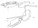
- FIG. FIG. 2 is a perspective view showing a rocking actuator and a mirror according to the first embodiment.
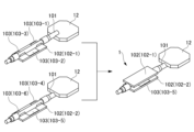
- FIG. 1 is a perspective view illustrating a configuration of a rocking actuator according to a first embodiment.
- FIG. 2 is a perspective view showing a state in which a linear motion shaft is removed from the rocking actuator according to the first embodiment.
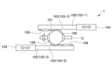
- 3 is a diagram illustrating the oscillation actuator and the mirror according to the first embodiment, as viewed from a direction perpendicular to the axial direction of the rotation shaft.
- FIG. 5 is a view taken along line A in FIG. 4 and seen from the axial direction of the rotating shaft.
- FIG. 5 is a view taken along line B in FIG. 4 as viewed from the axial direction of the rotation shaft.
- FIG. 7 is a view seen from the axial direction of the rotating shaft, for explaining the operation of rotating the rotating shaft in the clockwise direction in FIG. 6 .
- 7 is a view seen from the axial direction of the rotating shaft, for explaining the operation of rotating the rotating shaft in the counterclockwise direction in FIG. 6 .
- FIG. 8 is a view seen from the axial direction of the rotating shaft to explain the operation of rotating the rotating shaft in the clockwise direction in FIG. 7 .
- FIG. 8 is a view seen from the axial direction of the rotating shaft, for explaining the operation of rotating the rotating shaft in the counterclockwise direction in FIG. 7 .
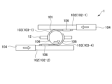
- FIG. 13 is a diagram for explaining a rocking actuator according to a second embodiment, as viewed from a direction perpendicular to the axial direction of a rotation shaft.
- the same reference numerals are used for configurations common to other embodiments, and only the configurations, operations and effects different from other embodiments will be described.
- six connecting sheets 103 are provided, but this number is not limited.
- the configurations of the rotating shaft, linear shaft, connecting sheet, etc. are not limited to the rotating shaft 101, linear shaft 102, connecting sheet 103, etc.
- the linear shaft 102 is composed of two linear shafts 102-1 and 102-2, but is not limited to this.
- the linear shaft 102 may be composed of either one of the linear shafts 102-1 and 102-2.
- the oscillating actuator of the present disclosure is an oscillating actuator whose rotating shaft does not rotate once, and is used in industrial machines such as machine tools and robots.
- the oscillating actuator of the present disclosure is applied to a galvano motor 1 that is required to rotate and position a commanded rotation angle in the shortest time, as an example of the oscillating actuator of the present disclosure.
- the galvano motor 1 configured with the oscillating actuator of this embodiment is, for example, a single-phase drive galvano motor that scans laser light.
- the galvano motor 1 of this embodiment is configured with a rotating shaft 101, a linear shaft 102, a connecting sheet 103, and a thrust generating device 104. Therefore, the galvano motor 1 of this embodiment can obtain high responsiveness and high torque despite its small size, has small rotor inertia, suppresses the occurrence of backlash, and suppresses the reduction in rigidity.
- FIG. 1 is a perspective view that shows a schematic diagram of a laser light source 11 and a galvanometer scanner 10.
- FIG. 2 is a perspective view that shows a galvanometer motor 1 and a mirror 12. As shown in FIG. 1, the laser light source 11 and the galvanometer scanner 10 are disposed above a table T on which a workpiece W is placed during laser processing.
- the laser light source 11 is composed of various laser oscillators equipped with a laser medium, an optical resonator, an excitation source, etc., and emits laser light toward the galvanometer scanner 10.
- the galvanometer scanner 10 includes a plurality of mirrors 12, 12 that sequentially reflect the laser light emitted from the laser light source 11, and galvanometer motors 1, 1 according to this embodiment that rotate each of the plurality of mirrors 12, 12 around rotation axes Ra, Rb.
- the number and arrangement of the mirrors 12 and galvanometer motors 1 are not particularly limited.
- the laser light emitted from the laser light source 11 is reflected in sequence by two mirrors 12, 12, and then reaches the workpiece W on the table T.
- the two galvanometer motors 1, 1 rotate the two mirrors 12, 12, respectively, the angle of incidence of the laser light incident on each mirror 12, 12 changes continuously.
- the laser light reaching the workpiece W can be scanned along a predetermined scanning path on the top surface of the workpiece W.
- FIG. 3 is a perspective view illustrating the configuration of the galvanometer motor 1.
- FIG. 5 is a view illustrating the galvanometer motor 1 and the mirror 12, viewed from a direction perpendicular to the axial direction of the rotation shaft 101.
- FIG. 6 is a view taken along the line A in FIG. 4, viewed from the axial direction of the rotation shaft 101.
- FIG. 7 is a view taken along the line B in FIG. 4, viewed from the axial direction of the rotation shaft 101.
- FIG. 8 is a view taken along the axial direction of the rotation shaft 101, viewed from ...
- the galvanometer motor 1 comprises a rotating shaft 101, a linear shaft 102, a connecting sheet 103, a thrust generator 104, and an encoder (not shown) that is provided on a part of these movable parts for controlling the operation of the movable parts, and is housed, for example, in a motor case (not shown).
- the rotating shaft 101, the linear shaft 102, and the connecting sheet 103 drive-connect the rotating shaft 101 and the linear shaft 102, and constitute a linear-rotation conversion mechanism that converts linear motion into rotational motion.
- the encoder (not shown), a linear encoder is attached to the linear part that performs linear motion, or a rotary encoder is attached to the rotating shaft that performs rotational motion.
- the rotating shaft 101 has a cylindrical shape, and the base end of the rotating shaft 101 is supported and guided by a bearing or the like (not shown) so that it can rotate around the axis of the rotating shaft 101.
- a mirror 12 is fixed to the tip of the rotating shaft 101.
- the mirror 12 is positioned so that the surface of the mirror 12 is parallel to the rotating shaft 101.
- the mirror 12 is configured so that as the rotating shaft 101 rotates, the mirror 12 rotates; more specifically, the mirror 12 swings up to about 20 degrees in the clockwise or counterclockwise direction around the axis of the rotating shaft 101.
- the galvanometer motor 1 is applied to a galvanometer scanner, so the mirror 12 is configured to swing up to about 20 degrees in the clockwise or counterclockwise direction around the axis of the rotating shaft 101.
- the galvanometer motor itself is capable of rotating the rotating shaft 101 in a range of 180 degrees or less in the clockwise or counterclockwise direction around the axis of the rotating shaft 101 for industrial use, and in this embodiment, the rotating shaft 101 can be rotated in a range of 90 degrees or less in the clockwise or counterclockwise direction around the axis of the rotating shaft 101.
- the linear shaft 102 is composed of two pieces, linear shaft 102-1 and linear shaft 102-2.
- the linear shaft 102-1 in the upper left of FIG. 3 is turned over, and the linear shafts 102-1 and 102-2 are arranged facing each other with the rotating shaft 101 in between.
- the linear shaft 102 is composed of a plate-like member having a rigidity that does not bend easily.
- the rotating shaft 101 abuts against one surface of the linear shaft 102 (for example, the upper surfaces of the linear shafts 102-1 and 102-2 shown in FIG. 3) via a connecting sheet 103.
- the linear shaft 102 is linearly guided by a linear guide (not shown) or the like, and is movable forward and backward in a direction perpendicular to the axis of the rotating shaft 101 and in a direction parallel to one surface and the other surface of the linear shaft 102.
- the linear shaft 102 has a thrust generator 104, which is connected to the linear shafts 102-1 and 102-2.
- the thrust generator 104 is preferably one capable of controlling force, and is configured with a linear motor or a high-speed response solid actuator such as a piezoelectric element that can move the linear shaft 102 by moving it back and forth while the linear shaft 102 is linearly guided by a linear guide (not shown).
- a linear motor copper wire is usually used for the motor coil, but aluminum wire may be used to reduce inertia.
- linear guides include rolling guides, sliding guides, parallel spring guides, and static pressure air guides, and air guides are preferred when inertia is to be reduced as much as possible.
- a preload is applied to the linear shaft 102 by a preload applying device (not shown). This allows the linear shaft 102 to be kept in close contact with the rotating shaft 101 via the connecting sheet 103.
- a part of the connecting sheet 103 is connected to the rotating shaft 101 in a state where it is wound around the rotating shaft 101 along the circumferential surface of the rotating shaft 101.
- one end of each of the connecting sheets 103-1 and 103-4 is fixed to a diameter position of the rotating shaft 101 by a screw 106 on the side of the circumferential surface of the rotating shaft 101.
- the connecting sheet 103-4 extends from one end along the circumferential surface of the rotating shaft 101 to a contact position where the rotating shaft 101 and the linear motion shaft 102-2 are in close contact (the bottom end of the rotating shaft 101 in Figure 6), and from that position, it extends in a direction perpendicular to the axial direction of the rotating shaft 101 along one surface of the linear motion shaft 102-2 (for example, the upper surface of the linear motion shaft 102-2 shown in Figure 6).
- the other end of the connecting sheet 103-4 is fixed at a predetermined distance parallel to the axial direction of the rotating shaft 101 by screws 106 on that one surface of the linear motion shaft 102-2.
- the connecting sheet 103-1 extends from one end along the circumferential surface of the rotating shaft 101, connected in a wound state, to the contact position where the rotating shaft 101 and the linear motion shaft 102-1 are in close contact (the uppermost end of the rotating shaft 101 in FIG. 6), and then extends from that position along one surface of the linear motion shaft 102-1 (for example, the lower surface of the linear motion shaft 102-1 shown in FIG. 6) in a direction perpendicular to the axial direction of the rotating shaft 101.
- the other end of the connecting sheet 103-1 is fixed at a predetermined interval by screws 106 on the one surface of the linear motion shaft 102-1 parallel to the axial direction of the rotating shaft 101.
- the connecting sheet 103 has a thickness of 50 ⁇ m or less, and can be wound around the rotating shaft 101 along the circumferential surface of the rotating shaft 101 or can be stretched along one surface of the linear shaft 102 as the rotating shaft 101 rotates, and is made of a material that does not expand or contract within a tolerance range when tension is applied to the connecting sheet 103 when the rotating shaft 101 is rotated integrally with the mirror 12. That is, the connecting sheet 103 is made of a metal such as SUS steel in this embodiment, but is not limited to metals such as SUS steel, and is preferably made of a material with a large Young's modulus, and may be made of a thin sheet of CFRP (carbon fiber reinforced plastic), for example.
- CFRP carbon fiber reinforced plastic
- a plurality of connecting sheets 103 are provided, and are connected and fixed to the rotating shaft 101 and the linear motion shaft 102 at a plurality of locations.
- three rectangular connecting sheets 103 namely, connecting sheet 103-1, connecting sheet 103-2, and connecting sheet 103-3, are arranged in this order, mainly on the upper side of the rotating shaft 101, so as to be adjacent to each other in the axial direction of the rotating shaft 101, and are fixed to the rotating shaft 101 and the linear motion shaft 102-1 (see FIG. 3), respectively.
- connecting sheet 103 namely, connecting sheet 103-4, connecting sheet 103-5, and connecting sheet 103-6, are arranged in this order, mainly on the lower side of the rotating shaft 101, so as to be adjacent to each other in the axial direction of the rotating shaft 101, and are fixed to the rotating shaft 101 and the linear motion shaft 102-2 (see FIG. 3), respectively.
- the width of connecting sheet 103-2 in the axial direction of rotating shaft 101 is approximately equal to the sum of the widths of connecting sheets 103-1 and 103-3 in the same direction.
- the width of connecting sheet 103-5 in the axial direction of rotating shaft 101 is approximately equal to the sum of the widths of connecting sheets 103-4 and 103-6 in the same direction.
- the connecting sheets 103-4 and 103-6 When viewed in the direction shown in FIG. 6 (from the bottom left to the top right in FIG. 4), the connecting sheets 103-4 and 103-6 are wrapped around the rotating shaft 101 in a counterclockwise direction and connected along the right-hand portion of the circumferential surface of the rotating shaft 101 as shown in FIGS. 4 and 6.
- the portions of the connecting sheets 103-4 and 103-6 other than the portions wrapped around and connected to the circumferential surface of the rotating shaft 101 extend along the upper surface of the linear motion shaft 102 (see FIG. 3) to the left of the bottom end of the rotating shaft 101 in FIGS. 4 and 6.
- connecting sheets 103-1 and 103-3 are wrapped around the rotating shaft 101 in a counterclockwise direction and connected along the left-hand portion of the circumferential surface of the rotating shaft 101 shown in FIG. 4 and FIG. 6.
- the portions of connecting sheets 103-1 and 103-3 other than the portions wrapped around and connected to the circumferential surface of the rotating shaft 101 extend along the underside of the linear motion shaft 102 (see FIG. 3) to the right of the top end of the rotating shaft 101 in FIG. 4 and FIG. 6.
- the connecting sheet 103-2 When viewed in the direction shown in FIG. 7 (from the lower left to the upper right in FIG. 4), the connecting sheet 103-2 is wrapped around the rotating shaft 101 in a clockwise direction and is connected along the right-hand portion of the circumferential surface of the rotating shaft 101 as shown in FIGS. 4 and 7.
- the portion of the connecting sheet 103-2 other than the portion wrapped around and connected to the circumferential surface of the rotating shaft 101 extends along the underside of the linear motion shaft 102 (see FIG. 3) to the left of the top end of the rotating shaft 101 in FIGS. 4 and 7.
- the connecting sheet 103-5 When viewed in the direction shown in FIG. 7 (from the bottom left to the top right in FIG. 4), the connecting sheet 103-5 is wrapped around the rotating shaft 101 in a clockwise direction and is connected along the left portion of the circumferential surface of the rotating shaft 101 as shown in FIGS. 4 and 7.
- the portion of the connecting sheet 103-5 other than the portion wrapped around and connected to the circumferential surface of the rotating shaft 101 extends along the top surface of the linear motion shaft 102 (see FIG. 3) to the right of the bottom end of the rotating shaft 101 in FIGS. 4 and 7.
- connecting sheet 103-1, 103-2, 103-3, 103-4, 103-5, and 103-6 in this manner, when the linear shaft 102 is moved by the thrust generating device 104 as described below, the tension of the connecting sheets 103 cancels the moment acting on the rotating shaft 101 in a direction parallel to the upper surface of the linear shaft 102.
- connecting sheet 103-3 appears in place of connecting sheet 103-1 shown in FIG. 6 and the like in the cross section taken along line A in FIG. 4
- connecting sheet 103-6 appears in place of connecting sheet 103-4.
- the rotating shaft 101 is rotated clockwise together with the mirror 12.
- the portions of the connecting sheet 103-4 and connecting sheet 103-6 that were wrapped around the right side of the rotating shaft 101 gradually move away from the rotating shaft 101 from their lower parts, and are brought into a state where they are aligned with the upper surface of the linear motion shaft 102-2, and are connected to the upper surface of the linear motion shaft 102.
- the connecting sheet 103-5 that was wrapped around the left side of the rotating shaft 101 is gradually wound around the rotating shaft 101 from its lower part.
- connecting sheet 103-1 and connecting sheet 103-3 that were wrapped around the circumferential surface of the left side of the rotating shaft 101 in FIG. 8 gradually move away from the circumferential surface of the rotating shaft 101 from their upper parts, and are brought into a state where they are aligned with the lower surface of the linear motion shaft 102-1, and are connected to the lower surface of the linear motion shaft 102.
- connecting sheet 103-2 that was wrapped around the circumferential surface of the right side of the rotating shaft 101 in FIG. 10 is gradually wound around the circumferential surface of the rotating shaft 101 from its upper part.
- the rotating shaft 101 is rotated counterclockwise together with the mirror 12.
- the portion of the connecting sheet 103-5 that was wrapped around the left side of the rotating shaft 101 gradually moves away from the rotating shaft 101 from its lower part and is brought into line with the upper surface of the linear motion shaft 102-2 and is connected to the upper surface of the linear motion shaft 102-2.
- the portion of the connecting sheet 103-2 that was wrapped around the right side of the rotating shaft 101 gradually moves away from the rotating shaft 101 from its upper part and is brought into line with the lower surface of the linear motion shaft 102-1 and is connected to the lower surface of the linear motion shaft 102-1.
- connecting sheet 103-4 and connecting sheet 103-6 that were wound around the circumferential surface of the rotating shaft 101 on the right side are gradually wound around the circumferential surface of the rotating shaft 101 from their lower parts.
- connecting sheet 103-1 and connecting sheet 103-3 that were wound around the circumferential surface of the rotating shaft 101 on the left side are gradually wound around the circumferential surface of the rotating shaft 101 from their upper parts.
- the galvanometer motor 1 includes a rotating shaft 101, a linear shaft 102, and a linear motion rotation conversion mechanism that drivingly connects the rotating shaft 101 and the linear motion shaft 102 and converts linear motion into rotational motion, the linear motion shaft 102 having a thrust generating device, and the linear motion rotation conversion mechanism having a connecting sheet 103, a part of the connecting sheet 103 being connected and fixed in a state where it is wound around the rotating shaft 101, and another part of the connecting sheet 103 being connected and fixed in a state where it is aligned with the linear motion shaft 102.
- the connecting sheet 103 is made of metal and has a thickness of 50 ⁇ m or less. This makes it possible to achieve both flexibility and strength for the connecting sheet 103.
- the connecting sheet 103 is connected and fixed to the rotating shaft 101 and the linear motion shaft 102 at multiple points, and the connecting sheet 103 is connected to the rotating shaft 101 by being wound clockwise and counterclockwise, respectively. This makes it possible for a pulling force to be applied to the connecting sheet 103 when the linear motion shaft 102 moves to either the left or right.
- the connecting sheet 103 is positioned so as to cancel the moment acting on the rotating shaft 101 due to the tension of the connecting sheet 103. This makes it possible to prevent bending of the rotating shaft 101 and also to reduce the radial load acting on the bearing that rotatably supports the rotating shaft 101.
- the connecting sheet 103 is fixed to the rotating shaft 101 and the linear shaft 102 with screws 106. This makes it possible to prevent the connecting sheet 103 from shifting relative to the linear shaft 102, and improves the natural frequency of the linear-rotation conversion mechanism.
- a preload is applied to the rotating shaft 101 and the linear shaft 102 to bring them into close contact with each other.
- the thrust generating device 104 has a high-speed response solid actuator such as a linear motor or a piezoelectric element. This makes it possible to improve the natural frequency of the linear shaft 102 as a mover.
- the galvanometer motor 1A according to the second embodiment differs from the galvanometer motor 1 according to the first embodiment in that it is not provided with a thrust generator 104 and is provided with a torque generator 104A. Other than these, it has the same configuration as the first embodiment.
- FIG. 12 is a view illustrating the oscillating actuator 1A as seen from a direction perpendicular to the axial direction of the rotating shaft 101A.
- the linear shaft 102 (102-1, 102-2) is not provided with a thrust generating device 104.
- a torque generating device 104A consisting of a normal motor is connected to the end of the rotating shaft 101A.
- the torque generating device 104A is driven, the rotating shaft 101A rotates, and as a result, the linear shaft 102 (102-1, 102-2) moves back and forth due to the pulling force of the connecting sheets 103 (103-1, 103-2, 103-3) and the connecting sheets 103 (103-4, 103-5, 103-6) not shown.
- the rotating shaft 101A, the linear shaft 102 (102-1, 102-2), the connecting sheet 103 (103-1, 103-2, 103-3), and the connecting sheet 103 (103-4, 103-5, 103-6) not shown in the figure constitute a linear motion rotation conversion mechanism that drives and connects the rotating shaft 101A and the linear motion shaft 102 (102-1, 102-2) and converts rotational motion into linear motion.
- the configuration of the rotating shaft, linear shaft, connecting sheets, etc. is not limited to the rotating shaft 101, linear shaft 102, connecting sheet 103, etc.
- the linear shaft 102 is composed of two linear shafts 102-1 and 102-2, but is not limited to this.
- the linear shaft 102 may be composed of either one of the linear shafts 102-1 and 102-2.
Landscapes
- Physics & Mathematics (AREA)
- General Physics & Mathematics (AREA)
- Optics & Photonics (AREA)
- Engineering & Computer Science (AREA)
- General Engineering & Computer Science (AREA)
- Mechanical Engineering (AREA)
- Transmission Devices (AREA)
- Connection Of Motors, Electrical Generators, Mechanical Devices, And The Like (AREA)
Priority Applications (4)
| Application Number | Priority Date | Filing Date | Title |
|---|---|---|---|
| CN202380096485.6A CN120882992A (zh) | 2023-04-13 | 2023-04-13 | 摆动致动器 |
| DE112023005661.7T DE112023005661T5 (de) | 2023-04-13 | 2023-04-13 | Schwenkaktuator |
| JP2025513591A JPWO2024214239A1 (https=) | 2023-04-13 | 2023-04-13 | |
| PCT/JP2023/015002 WO2024214239A1 (ja) | 2023-04-13 | 2023-04-13 | 揺動アクチュエータ |
Applications Claiming Priority (1)
| Application Number | Priority Date | Filing Date | Title |
|---|---|---|---|
| PCT/JP2023/015002 WO2024214239A1 (ja) | 2023-04-13 | 2023-04-13 | 揺動アクチュエータ |
Publications (1)
| Publication Number | Publication Date |
|---|---|
| WO2024214239A1 true WO2024214239A1 (ja) | 2024-10-17 |
Family
ID=93058877
Family Applications (1)
| Application Number | Title | Priority Date | Filing Date |
|---|---|---|---|
| PCT/JP2023/015002 Ceased WO2024214239A1 (ja) | 2023-04-13 | 2023-04-13 | 揺動アクチュエータ |
Country Status (4)
| Country | Link |
|---|---|
| JP (1) | JPWO2024214239A1 (https=) |
| CN (1) | CN120882992A (https=) |
| DE (1) | DE112023005661T5 (https=) |
| WO (1) | WO2024214239A1 (https=) |
Citations (3)
| Publication number | Priority date | Publication date | Assignee | Title |
|---|---|---|---|---|
| JPS5956671U (ja) * | 1982-10-08 | 1984-04-13 | 株式会社リコー | フロツピ−デイスク装置の磁気ヘツド駆動用ベルト取付機構 |
| JPH0635715U (ja) * | 1992-10-19 | 1994-05-13 | 株式会社ニフコ | ばねを用いた駆動装置 |
| JP2007223039A (ja) * | 2004-11-22 | 2007-09-06 | Matsushita Electric Ind Co Ltd | 関節構造体及びロボットアーム |
-
2023
- 2023-04-13 JP JP2025513591A patent/JPWO2024214239A1/ja active Pending
- 2023-04-13 WO PCT/JP2023/015002 patent/WO2024214239A1/ja not_active Ceased
- 2023-04-13 DE DE112023005661.7T patent/DE112023005661T5/de active Pending
- 2023-04-13 CN CN202380096485.6A patent/CN120882992A/zh active Pending
Patent Citations (3)
| Publication number | Priority date | Publication date | Assignee | Title |
|---|---|---|---|---|
| JPS5956671U (ja) * | 1982-10-08 | 1984-04-13 | 株式会社リコー | フロツピ−デイスク装置の磁気ヘツド駆動用ベルト取付機構 |
| JPH0635715U (ja) * | 1992-10-19 | 1994-05-13 | 株式会社ニフコ | ばねを用いた駆動装置 |
| JP2007223039A (ja) * | 2004-11-22 | 2007-09-06 | Matsushita Electric Ind Co Ltd | 関節構造体及びロボットアーム |
Also Published As
| Publication number | Publication date |
|---|---|
| JPWO2024214239A1 (https=) | 2024-10-17 |
| CN120882992A (zh) | 2025-10-31 |
| DE112023005661T5 (de) | 2025-11-06 |
Similar Documents
| Publication | Publication Date | Title |
|---|---|---|
| US5157300A (en) | Vibration wave driven motor apparatus | |
| KR100872031B1 (ko) | 자기구동기를 이용한 비접촉식 스캐너 | |
| JP5929139B2 (ja) | アクチュエーター、ロボットハンド、ロボット、電子部品搬送装置、電子部品検査装置およびプリンター | |
| JP2019141868A (ja) | レーザ加工装置 | |
| JP2000081588A (ja) | ガルバノミラーアクチュエータ | |
| JP5404540B2 (ja) | ガルバノメータスキャナ | |
| WO2024214239A1 (ja) | 揺動アクチュエータ | |
| JP4945587B2 (ja) | 圧電モータ、圧電モータ付き電子機器及び圧電モータを備えたステージ | |
| JP2925835B2 (ja) | レーザ加工装置用手首構造 | |
| JP4976885B2 (ja) | 鏡筒の旋回機構 | |
| JP2004074166A (ja) | 光学スキャナおよびレーザ加工装置 | |
| JP2727379B2 (ja) | レーザーロボットの制御方法 | |
| JP5388948B2 (ja) | ガルバノスキャナ、及びレーザ加工装置 | |
| EP3966924A1 (fr) | Moteur piezoelectrique a onde progressive de flexion | |
| JP4222866B2 (ja) | 2軸複合モータ | |
| JP2018089769A (ja) | 産業用ロボット及びパラレルリンクロボット | |
| JP6624961B2 (ja) | 旋回駆動装置 | |
| JP2001161084A (ja) | 超音波モータを用いた直動機構およびそれを用いた電子機器 | |
| JP7547173B2 (ja) | 振動型アクチュエータ、多軸ステージ、多関節ロボット及び装置 | |
| JP4571742B2 (ja) | ビーム偏向装置 | |
| JPH09303383A (ja) | 回転装置及び光偏向装置 | |
| JP5153583B2 (ja) | 駆動装置 | |
| JP5141652B2 (ja) | 直動回転アクチュエータ | |
| JPH03166083A (ja) | ロボツト用手首装置及び産業用ロボツト | |
| JP2025166390A (ja) | ガルバノスキャナユニット及びレーザ加工機 |
Legal Events
| Date | Code | Title | Description |
|---|---|---|---|
| 121 | Ep: the epo has been informed by wipo that ep was designated in this application |
Ref document number: 23933015 Country of ref document: EP Kind code of ref document: A1 |
|
| ENP | Entry into the national phase |
Ref document number: 2025513591 Country of ref document: JP Kind code of ref document: A |
|
| WWE | Wipo information: entry into national phase |
Ref document number: 2025513591 Country of ref document: JP |
|
| WWE | Wipo information: entry into national phase |
Ref document number: 112023005661 Country of ref document: DE |
|
| WWE | Wipo information: entry into national phase |
Ref document number: 202380096485.6 Country of ref document: CN |
|
| WWP | Wipo information: published in national office |
Ref document number: 202380096485.6 Country of ref document: CN |
|
| 122 | Ep: pct application non-entry in european phase |
Ref document number: 23933015 Country of ref document: EP Kind code of ref document: A1 |