WO2024214190A1 - 多管式貫流ボイラー及び水管列 - Google Patents
多管式貫流ボイラー及び水管列 Download PDFInfo
- Publication number
- WO2024214190A1 WO2024214190A1 PCT/JP2023/014763 JP2023014763W WO2024214190A1 WO 2024214190 A1 WO2024214190 A1 WO 2024214190A1 JP 2023014763 W JP2023014763 W JP 2023014763W WO 2024214190 A1 WO2024214190 A1 WO 2024214190A1
- Authority
- WO
- WIPO (PCT)
- Prior art keywords
- water tube
- water
- combustion chamber
- tube row
- row
- Prior art date
- Legal status (The legal status is an assumption and is not a legal conclusion. Google has not performed a legal analysis and makes no representation as to the accuracy of the status listed.)
- Ceased
Links
Images




Classifications
-
- F—MECHANICAL ENGINEERING; LIGHTING; HEATING; WEAPONS; BLASTING
- F22—STEAM GENERATION
- F22B—METHODS OF STEAM GENERATION; STEAM BOILERS
- F22B21/00—Water-tube boilers of vertical or steeply-inclined type, i.e. the water-tube sets being arranged vertically or substantially vertically
- F22B21/22—Water-tube boilers of vertical or steeply-inclined type, i.e. the water-tube sets being arranged vertically or substantially vertically built-up from water tubes of form other than straight or substantially straight
- F22B21/30—Water-tube boilers of vertical or steeply-inclined type, i.e. the water-tube sets being arranged vertically or substantially vertically built-up from water tubes of form other than straight or substantially straight bent in U-loop form
-
- F—MECHANICAL ENGINEERING; LIGHTING; HEATING; WEAPONS; BLASTING
- F22—STEAM GENERATION
- F22B—METHODS OF STEAM GENERATION; STEAM BOILERS
- F22B37/00—Component parts or details of steam boilers
- F22B37/02—Component parts or details of steam boilers applicable to more than one kind or type of steam boiler
- F22B37/10—Water tubes; Accessories therefor
Definitions
- the present invention relates to a multi-tube once-through boiler that generates steam by heating a large number of water tubes, and in particular to a multi-tube once-through boiler that can use recycled oil as fuel and the structure of the water tube rows used in the multi-tube once-through boiler.
- a multi-tube once-through boiler has multiple water tubes arranged vertically in a cylindrical combustion tube with top and bottom, and two rows of water tubes, an inner water tube row 3 and an outer water tube row 4, are connected between an annular upper header 1 and a lower header 2.
- the space between adjacent inner water tube rows 3 and adjacent outer water tube rows 4 is blocked (closing fins 8), and part of the space between the water tubes in the inner water tube row 3 is opened (inner smoke vent 5), forming a combustion gas passage 7 between the inner water tube row 3 and the outer water tube row 4, and boiler water is supplied to each water tube from the lower header 2.
- fuel is supplied to the burner 10 installed in the combustion tube and burned to generate combustion gas in the combustion chamber 9, and the combustion gas is supplied from the combustion gas passage 7 to the outside of the multiple water tubes to heat and evaporate the boiler water in the water tubes, and consumed steam is taken out from the upper header 1.
- the combustion exhaust gas passes through the combustion gas passage 7 and the outer smoke vent 6 and is discharged from the flue 12 as combustion exhaust gas with a reduced temperature.
- the peripheral portions of the upper header 1 and the lower header 2 are covered with a refractory material 13, and the entire combustion tube is covered with a heat insulating material 14.
- Patent Document 2 which is designed to use recycled oil (waste oil) as fuel for the combustion gas used to generate consumed steam.
- the combustion chamber is cylindrical and extends horizontally, and a door (lid) is formed on one end facing the combustion chamber, allowing the interior to be seen by opening and closing the door (lid).
- a door (lid) is formed on one end facing the combustion chamber, allowing the interior to be seen by opening and closing the door (lid).
- the combustion gas moves horizontally through the rows of water tubes arranged horizontally within the horizontally extending combustion chamber, which makes it difficult to uniformize the temperature within the combustion chamber, resulting in the problem of difficulty in efficiently heating the boiler water in the water tubes.
- the present invention was made in consideration of the above-mentioned circumstances, and aims to provide a multi-tube once-through boiler structure that can efficiently heat water tubes even when the water tube rows are arranged horizontally in the combustion chamber.
- the present invention provides a multi-tube once-through boiler (100) in which both ends of a plurality of water tubes are connected to each other, boiler water is supplied to each water tube, a combustion chamber (9) is formed inside each water tube, combustion gas from the combustion chamber is supplied to the outside of the plurality of water tubes to heat and evaporate the boiler water in the water tubes, and consumed steam is taken out, Using recycled oil as fuel, A door (lid 22) is formed on one end side facing the combustion chamber (9), and a burner (10) for supplying combustion gas to the combustion chamber (9) is installed on the outer surface of the door (lid 22);
- the combustion chamber (9) is cylindrical and extends horizontally.
- the water tubes are arranged on the left and right sides of the combustion chamber (9) and have an arc shape.
- the water tube row arranged on the left side of the combustion chamber (9) is connected to a left upper header (1L) provided at an upper end and a left lower header (2R) provided at a lower end, each of which is straight.
- the water tube row arranged on the right side of the combustion chamber (9) is connected to a straight right upper header (1R) provided at an upper end and a straight right lower header (2R) provided at a lower end,
- the water tube rows are composed of an inner water tube row (3) and an outer water tube row (4), each water tube of the outer water tube row (4) is disposed between each water tube of the inner water tube row (3), each water tube constituting the left and right inner water tube rows is connected by an inner closing fin (8A), and each water tube constituting the left and right outer water tube rows is connected by an outer closing fin (8B),
- a partition wall (30) is provided near the end of the inner water tube row (3) where the combustion gas is injected to partition the combustion chamber (9), so that the supplied combustion gas collides with the partition wall (30) and then flows back in its entirety and returns to the door (lid body 22) side.
- a plurality of heat absorbing pieces (50A) are attached along a circular arc surface to the outside of each water tube constituting the inner water tube row (3);
- a plurality of heat absorbing pieces (50B) are attached along a circular arc surface to the inside of each water tube constituting the outer water tube row (4).
- the inner water tube row (3) is characterized by having a plurality of heat absorbing pieces (50C) attached along a circular arc surface on the inside of each water tube.
- the system is characterized in that a flue (12) is formed on the upper side of the combustion chamber (9) opposite the door, and the heat absorbing pieces (50A, 50B) are arranged at an incline downward with respect to the flow direction of the combustion gas.
- the heat absorbing piece (50) is characterized by being attached to a range of 2/3 of the length of the water tube row from the opposite side to the door (lid body 22).
- each heat absorbing piece (50A, 50B) is 5 to 15 degrees with respect to the flow direction of the combustion gas.
- the heat absorbing pieces (50A, 50B, 50C) are characterized by having a recess (51) formed in the center.
- a water tube row consisting of a plurality of water tubes arranged in a cylindrical combustion chamber (9),
- the water tubes are arranged on the left and right sides of the combustion chamber, respectively, and have an arc shape.
- the water tube row arranged on the left side of the combustion chamber (9) is connected to a left upper header (1L) provided at an upper end and a left lower header (2L) provided at a lower end, each of which is linear;
- the water tube row arranged on the right side of the combustion chamber (9) is connected to a straight right upper header (1R) provided at an upper end and a straight right lower header (2R) provided at a lower end,
- the water tube rows are composed of an inner water tube row (3) and an outer water tube row (4), each water tube of the outer water tube row (4) is disposed between each water tube of the inner water tube row (3), each water tube constituting the left and right inner water tube rows (3) is connected by an inner closing fin (8A), and each water tube constituting the left and right outer water tube rows (4) is connected by
- the heating efficiency of the boiler water in the water tubes can be improved by attaching heat absorbing pieces (50A, 50B, 50C) to each water tube constituting the water tube rows (3, 4).
- each heat absorbing piece (50A, 50B, 50C) at an incline downward with respect to the flow direction (horizontal direction) of the combustion gas in the combustion chamber (9), the flow of the combustion gas can be controlled to equalize the temperature in the combustion chamber, thereby improving heating efficiency.
- FIG. 1 is a side view illustrating a multi-tubular once-through boiler according to one embodiment of the present invention.
- FIG. 1 is a front view illustrating a multi-tube once-through boiler according to one embodiment of the present invention.
- FIG. 4 is a front view illustrating an inner water tube row and an outer water tube row.
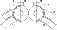
- FIG. 4 is a partial cross-sectional explanatory view showing the connection structure between the upper header and the inner and outer water pipes.
- FIG. 4 is an explanatory side view showing an inner water tube row and an outer water tube.
- FIG. 2 is a plan view perspective explanatory diagram for explaining the structure inside the main body of a multi-tube once-through boiler.
- FIG. 1 is a side view illustrating a multi-tubular once-through boiler according to one embodiment of the present invention.
- FIG. 1 is a front view illustrating a multi-tube once-through boiler according to one embodiment of the present invention.
- FIG. 4 is a front view illustrating an inner water tube row and an
- FIG. 2 is a side perspective view illustrating the internal structure of the main body of a multi-tubular once-through boiler.
- FIG. 4 is a side cross-sectional explanatory view showing a state in which a heat absorbing piece is attached to a water tube row.
- 9 is a cross-sectional view taken along line IX-IX of FIG. 8 .
- An explanatory cross-sectional view taken along the line XX in Figure 8. 13 is a side perspective explanatory view showing a state in which the heat absorbing pieces are attached to the water tube rows.
- FIG. 14 is an explanatory cross-sectional view taken along the line XIV-XIV of FIG. 13.
- FIG. 1 is a schematic diagram illustrating a conventional multi-tube once-through boiler.
- 16 is an explanatory cross-sectional view taken along the line AA in FIG. 15.
- the multi-tube once-through boiler of the present invention uses only recycled oil as fuel and as combustion gas for generating consumed steam.
- Recycled oils include various types of used mineral waste oils such as engine oil, waste cooking oils such as used tempura oil, waste animal and vegetable oils obtained mainly from animal fats and oils, and grease trap oil obtained by separating and storing oil in wastewater containing fats and oils discharged from kitchens of restaurants and other establishments using grease traps.
- used mineral waste oils such as engine oil
- waste cooking oils such as used tempura oil
- waste animal and vegetable oils obtained mainly from animal fats and oils
- grease trap oil obtained by separating and storing oil in wastewater containing fats and oils discharged from kitchens of restaurants and other establishments using grease traps.
- Figures 1 and 2 show the external appearance of a multi-tube once-through boiler 100, with a hinge section 21 attached to a cylindrical body 20 with a bottom, both ends of which are closed by closure plates 40a and 40b, and a lid 22 that serves as a door for opening and closing the front side of the body 20, which is rotatably attached to the hinge section 21.
- a burner 10 is installed on the outer surface of the lid 22, and by supplying fuel to the burner 10 and burning it, combustion gas is generated in the combustion chamber 9 between the closure plates 40a and 40b on the lid 22 side inside the body 20.
- the surrounding area of the burner 10 on the combustion chamber 9 side is covered with fireproof material 13 ( Figure 6).
- the combustion gas generated in the combustion chamber 9 of the main body 20 heats a number of water tubes installed inside the main body 20 from the surface side, and is discharged as combustion exhaust gas from the flue 12 provided on the upper side of the combustion chamber on the opposite side to the lid 22 ( Figure 6).
- Water is supplied to the water tubes, and the area around each water tube is heated by the combustion gas generated in the combustion chamber 9 to generate steam.
- the steam is discharged to the outside as consumed steam from a piping line 81 via a steam separator 80 for removing large water droplets in the steam (Figs. 1 and 2).
- the steam separator 80 is equipped with a pressure gauge 82 for measuring the steam pressure and a safety valve 83 for releasing the steam when the pressure rises.
- a cylindrical combustion chamber 9 with a bottom is formed extending horizontally in the center of the main body 20 , and a plurality of arc-shaped water pipes are arranged so as to surround the inside of the combustion chamber 9 .
- the group of water tubes arranged on the left inside of the combustion chamber 9 is designated as the inner water tube row 3L, with each upper end connected by a straight left upper header 1L and each lower end connected by a straight left lower header 2L.
- the group of water tubes arranged on the right inside of the combustion chamber 9 is designated as the inner water tube row 3R, with each upper end connected by a straight right upper header 1R and each lower end connected by a straight right lower header 2R.
- the water tubes constituting the left and right inner water tube rows 3L, 3R are connected by closing fins 8A.
- water tubes are arranged between each water tube of the inner water tube row 3, and these water tube groups form the outer water tube row 4.
- the outer water tube rows 4 are arranged outside the left and right inner water tube rows 3, and like the left and right inner water tube rows 3, the upper ends of the left water tube group are connected to the left upper header 1L and the lower ends are connected to the left lower header 2L, and the upper ends of the right water tube group are connected to the right upper header 1R and the lower ends are connected to the right lower header 2R.
- the water tubes that make up the left and right outer water tube rows 4 are connected by closing fins 8B.
- a combustion chamber 9 is partitioned by installing a partition wall 30 made of thick heat-resistant stainless steel near the end of the inner water tube row 3 where the combustion gas is injected inside the main body 20, and the combustion gas injected from the burner 10 is configured so that it all flows back after colliding with the partition wall 30.
- a thermal insulation material 14 is arranged on the combustion chamber 9 side of the partition wall 30 to prevent deformation even when high-temperature combustion gas collides with it.
- a thermal insulation material 14 is also arranged on the inside of the closure plate 40b to prevent deformation.
- an inner smoke vent 5 is formed between the inner wall of the lid 22 and the end water tube, and a notch 5A is formed in the closing fin 8A that connects the water tubes of the inner water tube row 3. That is, as shown in FIG. 6, a notch (shaded area in FIG. 5) is formed in each of the three closing fins 8A from the lid 22 side.
- the notch is formed with three stages of opening, with the notch area being the widest on the lid 22 side. This is because the notch near the combustion gas outlet of the burner 10 is made larger (see FIG. 5), making it easier for the combustion gas that collides with the partition wall 30 and flows back to return to the vicinity of the lid 22 side.
- cutouts are formed for only three closing fins 8A out of the 18 water tubes in the inner water tube row 3, but the number of closing fins 8A that form cutouts should be about 10-20% of the total number of water tubes so as not to create resistance to the flow of combustion gas and to ensure that the combustion gas flows back, i.e., in this example, it is preferable to form two to three cutouts for the 18 water tubes that make up the inner water tube row 3.
- the water tube row is composed of an inner water tube row 3 and an outer water tube row 4, and each water tube of the outer water tube row 4 is arranged between each water tube of the inner water tube row 3, and each water tube constituting the left and right inner water tube rows 3 is connected by inner closing fins 8A, and each water tube constituting the left and right outer water tube rows 4 is connected by outer closing fins 8B.
- a plurality of heat absorbing pieces 50A having arcuate portions 51 that conform to the arcuate surfaces of the water tubes are attached at desired intervals to the outside of each water tube row that constitutes the inner water tube row 3.
- the heat absorbing pieces 50A are attached at intervals of, for example, about 5 to 60 mm (about 60 mm in the figure). It is believed that the closer the intervals, the higher the heat exchange efficiency.
- a plurality of heat absorbing pieces 50B of the same shape are attached at equal intervals inside each of the water tube rows constituting the outer water tube row 4.
- a recess 52 is formed in the center of the heat absorbing piece 50.
- This recess 52 prevents deformation of the portion of the heat absorbing piece 50 that is attached to the water pipe when the heat absorbing piece 50 becomes very hot.
- the heat absorbing pieces 50A and the heat absorbing pieces 50B are spaced at equal intervals, but they may be mounted at any intervals.
- the water tube row consists of an inner water tube row 3 consisting of 18 water tubes and an outer water tube row 4 consisting of 19 water tubes, and heat absorbing pieces 50A, 50B are attached to each water tube within a range of (2/3)L from the rear side (the opposite side to the lid body 22) of the longitudinal length L of the inner water tube row 3 (the distance between the ends of the inner water tube row).
- each heat absorbing piece 50 is mounted so that it is tilted downward with respect to the flow direction of the combustion gas in the combustion chamber 9 (from the lid 22 located at the front to the partition wall 30 located at the rear).
- the tilt angle ⁇ of each heat absorbing piece 50 is 5 to 15 degrees downward with respect to the horizontal flow direction (horizon), and approximately 10 degrees is preferable taking into account the injection speed of the combustion gas in a typical boiler.
- the high temperature of the combustion gas can be easily conducted to the water tube rows 3 and 4, improving the heat exchange efficiency.
- each heat absorbing piece 50 tilts downward with respect to the flow direction of the combustion gas, the flow of the combustion gas can be guided downward, and efficient heat exchange can be achieved even in the water tubes located below the combustion chamber 9.
- FIG. 13 and 14 show a multi-tube once-through boiler equipped with a water tube row according to another embodiment.
- heat absorbing pieces 50C are attached on the inside of each water tube row of the inner water tube row 3.
- the shape and other structure of the heat absorbing pieces 50C are the same as those of the heat absorbing pieces 50A and 50B.
- the heat absorbing pieces 50C are inclined downward with respect to the flow direction of the combustion gas and are attached on the inside of the inner water tube row 3 so as to guide the flow of the combustion gas downward.
- the heat absorbing pieces 50C are also attached to each water tube in a range of (2/3)L from the rear side (the opposite side to the lid body 22) with respect to the longitudinal length L of the inner water tube row 3. This is because by not having the heat absorbing piece 50C in the front (1/3) L range, the heat absorbing piece 50C is prevented from acting as resistance to the flow of the combustion gas that is forcefully sprayed from the burner 10.
- heat absorbing pieces 50C are attached on the inside of each water tube row of the inner water tube row 3, but the heat absorbing pieces 50A and 50B may be omitted and only heat absorbing pieces 50C may be attached on the inside of each water tube row of the inner water tube row 3.
- a flue 12 for carrying out combustion exhaust gas, which communicates with the combustion chamber 9, is disposed on the upper surface of the combustion chamber 9 opposite the door (lid 22) side.
- An upper cutout 41 corresponding to the upper semicircle is formed in a plurality of closing fins 8B (three water tubes in the illustrated example) of the outer water tube row 4 at a position facing the opening of the flue 12. The presence of the multiple upper cutouts 41 allows combustion exhaust gas to flow out from the gap between the inner water tube row 3 and the outer water tube row 4 on the closure plate 40b side through the upper cutouts 41 to the outside of the outer water tube row 4.
- the three upper cutouts 41 are also formed so that the opening area increases the closer they are to the partition wall 30. This is to allow the flow of combustion gas to reach as far back as possible, increasing the contact area with the water tube row and improving the efficiency of heat exchange with the combustion gas.
- a cyclone device (not shown) is connected above the flue 12 to separate powder (residual ash) from the combustion exhaust gas.
- the cyclone device is a powder separator that uses centrifugal separation to separate powdered residual ash mixed with the gas, and one with a general structure for separating gas and powder is used.
- a water supply port 23 is provided on the underside of the left lower header 2L and the right lower header 2R, and a steam exhaust port 24 is provided on the top surface of the left upper header 1L and the right upper header 1R.
- boiler water is supplied to each of the multiple water tubes arranged in an arc shape, and when combustion gas is supplied from the burner 10 to the combustion chamber 9, the combustion gas from the combustion chamber 9 comes into contact with the inner surface (the surface facing the combustion chamber 9) of each water tube of the inner water tube row 3, heating the boiler water in the water tubes.
- the combustion gas bounces off the partition wall 30 installed at the end of the combustion chamber 9 and is returned to the lid body 22 side, but as shown in Figure 6, it is led from the inner smoke vent 5 and the cutout portion 5A to the combustion gas passage 7 between the inner water tube row 3 and the outer water tube row 4, and comes into contact with the inner surface of the inner water tube row 3 and the inner surface of the outer water tube row 4, heating the boiler water in the water tubes.
- the boiler water in the water tubes of the inner water tube row 3 and the outer water tube row 4 is heated to become steam, and the steam is extracted from the steam exhaust ports 24 provided in the left upper header 1L and the right upper header 1R via the steam separator 80 and the piping line 81 and is consumed at the desired supply location.
- the temperature of the combustion gas is reduced by heating the boiler water in the water tubes, and the combustion gas is separated into combustion exhaust gas and powder through the flue 12 and the cyclone device and discharged to the outside.
Landscapes
- Engineering & Computer Science (AREA)
- Physics & Mathematics (AREA)
- Thermal Sciences (AREA)
- Mechanical Engineering (AREA)
- General Engineering & Computer Science (AREA)
- Gas Burners (AREA)
Priority Applications (2)
| Application Number | Priority Date | Filing Date | Title |
|---|---|---|---|
| PCT/JP2023/014763 WO2024214190A1 (ja) | 2023-04-11 | 2023-04-11 | 多管式貫流ボイラー及び水管列 |
| JP2025513548A JPWO2024214190A1 (https=) | 2023-04-11 | 2023-04-11 |
Applications Claiming Priority (1)
| Application Number | Priority Date | Filing Date | Title |
|---|---|---|---|
| PCT/JP2023/014763 WO2024214190A1 (ja) | 2023-04-11 | 2023-04-11 | 多管式貫流ボイラー及び水管列 |
Publications (1)
| Publication Number | Publication Date |
|---|---|
| WO2024214190A1 true WO2024214190A1 (ja) | 2024-10-17 |
Family
ID=93059145
Family Applications (1)
| Application Number | Title | Priority Date | Filing Date |
|---|---|---|---|
| PCT/JP2023/014763 Ceased WO2024214190A1 (ja) | 2023-04-11 | 2023-04-11 | 多管式貫流ボイラー及び水管列 |
Country Status (2)
| Country | Link |
|---|---|
| JP (1) | JPWO2024214190A1 (https=) |
| WO (1) | WO2024214190A1 (https=) |
Citations (6)
| Publication number | Priority date | Publication date | Assignee | Title |
|---|---|---|---|---|
| JPS5339761Y1 (https=) * | 1973-06-11 | 1978-09-27 | ||
| JPH0424244Y2 (https=) * | 1985-06-05 | 1992-06-08 | ||
| JP2002115802A (ja) * | 2000-08-04 | 2002-04-19 | Imex Co Ltd | 排熱回収装置 |
| JP2010175208A (ja) * | 2009-01-31 | 2010-08-12 | Samson Co Ltd | 多管式貫流ボイラ |
| JP2019190781A (ja) * | 2018-04-27 | 2019-10-31 | 猪野 貴行 | 多管式貫流ボイラー |
| JP2020060319A (ja) * | 2018-10-10 | 2020-04-16 | 株式会社日本サーモエナー | 小型貫流ボイラ |
-
2023
- 2023-04-11 JP JP2025513548A patent/JPWO2024214190A1/ja active Pending
- 2023-04-11 WO PCT/JP2023/014763 patent/WO2024214190A1/ja not_active Ceased
Patent Citations (6)
| Publication number | Priority date | Publication date | Assignee | Title |
|---|---|---|---|---|
| JPS5339761Y1 (https=) * | 1973-06-11 | 1978-09-27 | ||
| JPH0424244Y2 (https=) * | 1985-06-05 | 1992-06-08 | ||
| JP2002115802A (ja) * | 2000-08-04 | 2002-04-19 | Imex Co Ltd | 排熱回収装置 |
| JP2010175208A (ja) * | 2009-01-31 | 2010-08-12 | Samson Co Ltd | 多管式貫流ボイラ |
| JP2019190781A (ja) * | 2018-04-27 | 2019-10-31 | 猪野 貴行 | 多管式貫流ボイラー |
| JP2020060319A (ja) * | 2018-10-10 | 2020-04-16 | 株式会社日本サーモエナー | 小型貫流ボイラ |
Also Published As
| Publication number | Publication date |
|---|---|
| JPWO2024214190A1 (https=) | 2024-10-17 |
Similar Documents
| Publication | Publication Date | Title |
|---|---|---|
| CA2625536C (en) | Wood fired boiler | |
| KR20100038767A (ko) | 화목보일러 | |
| RU2242679C1 (ru) | Отопительное устройство | |
| KR101287693B1 (ko) | 하이브리드 보일러 | |
| KR101312963B1 (ko) | 화목연소장치 | |
| WO2024214190A1 (ja) | 多管式貫流ボイラー及び水管列 | |
| JP7099864B2 (ja) | 多管式貫流ボイラー | |
| JP3217062U (ja) | 多管式貫流ボイラー | |
| KR101500537B1 (ko) | 개선된 구조의 보일러 | |
| GB2280494A (en) | Boiler with baffled combustion chamber | |
| JP2021188801A (ja) | コンロバーナ、およびコンロバーナを搭載したガス加熱調理器 | |
| RU2327083C1 (ru) | Водогрейный котел | |
| RU84512U1 (ru) | Котел водогрейный, стальной, жаротрубный с дымогарными трубами | |
| CN110678706A (zh) | 具有涡流引导部的储水式锅炉 | |
| RU103173U1 (ru) | Конвекционная пламенная печь | |
| US2178376A (en) | Boiler construction | |
| WO2024089790A1 (ja) | 多管式貫流ボイラー及びその稼働方法 | |
| JPH08247437A (ja) | ガス直火型かまどの排気構造 | |
| RU2543924C1 (ru) | Котел отопительный водогрейный | |
| US1326198A (en) | Boileb | |
| RU2109223C1 (ru) | Отопительный котел | |
| RU2740962C1 (ru) | Конвекторная печь | |
| CN101275737B (zh) | 环保多层聚热锅炉 | |
| KR960000672B1 (ko) | 폐열 회수식 수직형 보일러 | |
| EP1983258A2 (en) | Wood fired boiler |
Legal Events
| Date | Code | Title | Description |
|---|---|---|---|
| 121 | Ep: the epo has been informed by wipo that ep was designated in this application |
Ref document number: 23932967 Country of ref document: EP Kind code of ref document: A1 |
|
| ENP | Entry into the national phase |
Ref document number: 2025513548 Country of ref document: JP Kind code of ref document: A |
|
| WWE | Wipo information: entry into national phase |
Ref document number: 2025513548 Country of ref document: JP |
|
| NENP | Non-entry into the national phase |
Ref country code: DE |
|
| 122 | Ep: pct application non-entry in european phase |
Ref document number: 23932967 Country of ref document: EP Kind code of ref document: A1 |