WO2024214135A1 - 遠心バレル研磨機 - Google Patents
遠心バレル研磨機 Download PDFInfo
- Publication number
- WO2024214135A1 WO2024214135A1 PCT/JP2023/014527 JP2023014527W WO2024214135A1 WO 2024214135 A1 WO2024214135 A1 WO 2024214135A1 JP 2023014527 W JP2023014527 W JP 2023014527W WO 2024214135 A1 WO2024214135 A1 WO 2024214135A1
- Authority
- WO
- WIPO (PCT)
- Prior art keywords
- barrel
- distance
- fixed
- turret
- measurement
- Prior art date
- Legal status (The legal status is an assumption and is not a legal conclusion. Google has not performed a legal analysis and makes no representation as to the accuracy of the status listed.)
- Ceased
Links
Images






Classifications
-
- B—PERFORMING OPERATIONS; TRANSPORTING
- B24—GRINDING; POLISHING
- B24B—MACHINES, DEVICES, OR PROCESSES FOR GRINDING OR POLISHING; DRESSING OR CONDITIONING OF ABRADING SURFACES; FEEDING OF GRINDING, POLISHING, OR LAPPING AGENTS
- B24B31/00—Machines or devices designed for polishing or abrading surfaces on work by means of tumbling apparatus or other apparatus in which the work and/or the abrasive material is loose; Accessories therefor
- B24B31/02—Machines or devices designed for polishing or abrading surfaces on work by means of tumbling apparatus or other apparatus in which the work and/or the abrasive material is loose; Accessories therefor involving rotary barrels
- B24B31/033—Machines or devices designed for polishing or abrading surfaces on work by means of tumbling apparatus or other apparatus in which the work and/or the abrasive material is loose; Accessories therefor involving rotary barrels having several rotating or tumbling drums with parallel axes
-
- B—PERFORMING OPERATIONS; TRANSPORTING
- B24—GRINDING; POLISHING
- B24B—MACHINES, DEVICES, OR PROCESSES FOR GRINDING OR POLISHING; DRESSING OR CONDITIONING OF ABRADING SURFACES; FEEDING OF GRINDING, POLISHING, OR LAPPING AGENTS
- B24B31/00—Machines or devices designed for polishing or abrading surfaces on work by means of tumbling apparatus or other apparatus in which the work and/or the abrasive material is loose; Accessories therefor
- B24B31/02—Machines or devices designed for polishing or abrading surfaces on work by means of tumbling apparatus or other apparatus in which the work and/or the abrasive material is loose; Accessories therefor involving rotary barrels
-
- B—PERFORMING OPERATIONS; TRANSPORTING
- B24—GRINDING; POLISHING
- B24B—MACHINES, DEVICES, OR PROCESSES FOR GRINDING OR POLISHING; DRESSING OR CONDITIONING OF ABRADING SURFACES; FEEDING OF GRINDING, POLISHING, OR LAPPING AGENTS
- B24B31/00—Machines or devices designed for polishing or abrading surfaces on work by means of tumbling apparatus or other apparatus in which the work and/or the abrasive material is loose; Accessories therefor
- B24B31/02—Machines or devices designed for polishing or abrading surfaces on work by means of tumbling apparatus or other apparatus in which the work and/or the abrasive material is loose; Accessories therefor involving rotary barrels
- B24B31/0212—Machines or devices designed for polishing or abrading surfaces on work by means of tumbling apparatus or other apparatus in which the work and/or the abrasive material is loose; Accessories therefor involving rotary barrels the barrels being submitted to a composite rotary movement
- B24B31/0218—Machines or devices designed for polishing or abrading surfaces on work by means of tumbling apparatus or other apparatus in which the work and/or the abrasive material is loose; Accessories therefor involving rotary barrels the barrels being submitted to a composite rotary movement the barrels are moving around two parallel axes, e.g. gyratory, planetary movement
-
- B—PERFORMING OPERATIONS; TRANSPORTING
- B24—GRINDING; POLISHING
- B24B—MACHINES, DEVICES, OR PROCESSES FOR GRINDING OR POLISHING; DRESSING OR CONDITIONING OF ABRADING SURFACES; FEEDING OF GRINDING, POLISHING, OR LAPPING AGENTS
- B24B31/00—Machines or devices designed for polishing or abrading surfaces on work by means of tumbling apparatus or other apparatus in which the work and/or the abrasive material is loose; Accessories therefor
- B24B31/12—Accessories; Protective equipment or safety devices; Installations for exhaustion of dust or for sound absorption specially adapted for machines covered by group B24B31/00
-
- B—PERFORMING OPERATIONS; TRANSPORTING
- B24—GRINDING; POLISHING
- B24B—MACHINES, DEVICES, OR PROCESSES FOR GRINDING OR POLISHING; DRESSING OR CONDITIONING OF ABRADING SURFACES; FEEDING OF GRINDING, POLISHING, OR LAPPING AGENTS
- B24B49/00—Measuring or gauging equipment for controlling the feed movement of the grinding tool or work; Arrangements of indicating or measuring equipment, e.g. for indicating the start of the grinding operation
- B24B49/12—Measuring or gauging equipment for controlling the feed movement of the grinding tool or work; Arrangements of indicating or measuring equipment, e.g. for indicating the start of the grinding operation involving optical means
Definitions
- the present invention relates to a centrifugal barrel polishing machine.
- Patent Document 1 describes a centrifugal barrel polishing machine in which a detection unit detects whether the fixing member that fixes the barrel tank to the barrel case is in a fixed form, and if it is not in a fixed form, the turret is not allowed to rotate.
- the barrel tank when determining whether the fixed member is in a fixed state, the barrel tank may deviate from the expected angle around the axis of rotation. In such a case, there is a concern that the detection result by the detection unit may erroneously determine that the fixed member is in a fixed state, even when the fixed member is not in a fixed state.
- the present invention has been made in consideration of the above problems, and aims to provide a centrifugal barrel finishing machine equipped with a fixing member for fixing a barrel tank or a barrel lid, which prevents centrifugal barrel finishing from being started when the fixing member is not in a fixed form.
- the centrifugal barrel finishing machine disclosed in this embodiment includes a turret that is rotated around a horizontally extending revolution axis, a barrel case that is rotated around a rotation axis that extends horizontally from a position eccentric to the revolution axis in the turret, a barrel tank housed in the barrel case, a fixing member that changes between a fixed form that fixes the barrel tank to the barrel case and a release form that releases the fixation of the barrel tank to the barrel case, a distance measuring unit that is arranged with a measurement direction along a substantially horizontal direction toward a detection area located on the revolution path of the barrel tank centered on the revolution axis, and a control unit.
- the fixing member has a measured part whose position changes between the fixed form and the release form, and when the measured part changes from the fixed form to the release form, it is displaced from the measurement direction of the distance measuring unit in a direction intersecting the measurement direction, and when the barrel tank is located in the detection area, the control unit determines whether or not a fixed distance indicating the horizontal distance to the measured part is measured by the distance measuring unit, and does not allow the rotation of the turret if the fixed distance is not measured.
- the control unit uses the distance measured by the distance measurement unit to determine whether the fixed member is in a fixed form. If the distance measurement unit does not measure the fixed distance, which indicates the horizontal distance to the measured part, the control unit does not allow the turret to rotate. This makes it possible to prevent centrifugal barrel polishing from being started when the fixed member is not in a fixed form.
- the present invention makes it possible to prevent centrifugal barrel polishing from being started in a centrifugal barrel polishing machine when the fixing member is not in a fixed state.
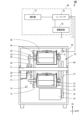
- FIG. 1 is a configuration diagram of a centrifugal barrel finishing machine.
- 2 is an enlarged view of the inside of FIG. 1 as seen in the direction of arrow A;
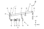
- FIG. FIG. 4 is a diagram illustrating a fixing member.
- FIG. 4 is a diagram illustrating a fixing member. 4 is a flowchart illustrating a procedure of a process executed by a control unit during operation.
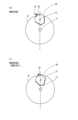
- 11A and 11B are diagrams illustrating determination of the fixing form of a fixing member.
- 11A and 11B are diagrams illustrating determination of the fixing form of a fixing member.
- 13A and 13B are diagrams illustrating determination of the fixing form of a fixing member in a comparative example.
- FIG. 6 is a configuration diagram of a centrifugal barrel finishing machine according to a second embodiment.
- FIG. 10 is an enlarged view of the inside as seen in the direction of arrow B in FIG. 9 .
- FIG. 4 is a diagram illustrating a fixing member.
- FIG. 4 is a diagram illustrating a fixing member.
- FIG. 11 is a configuration diagram of a centrifugal barrel finishing machine according to a third embodiment.
- the centrifugal barrel finishing machine is capable of performing centrifugal barrel finishing on a workpiece to be polished.
- the centrifugal barrel finishing machine 100 shown in Figures 1 and 2 mainly includes a housing 90, a barrel mechanism 20, a control unit 10 that controls the driving of the barrel mechanism 20, an area detection sensor 14, and a distance measurement sensor 15.
- the control unit 10 may be disposed outside the housing 90. Although not described here, the centrifugal barrel polishing machine 100 is connected to a power source, and power from this power source is supplied to the control unit 10 and the barrel mechanism unit 20 via a power circuit (not shown).
- the height of the centrifugal barrel finishing machine is defined as the up-down direction D3
- the direction horizontal to the installation surface is defined as the horizontal direction (a direction including a first direction D1 and a second direction D2 described below).
- the horizontal direction is also a direction that intersects with the up-down direction D3.
- the horizontal direction does not have to be strictly parallel to the installation surface, and may be inclined at a predetermined angle to the installation surface. Therefore, the horizontal direction also includes the concept of being "approximately horizontal" to the installation surface.
- the barrel mechanism 20 mainly comprises a revolution shaft 21, a turret 22, a motor 24, a rotation shaft 23, a barrel case 40, a barrel tank 50, and a fixing member 60.
- the revolution shaft 21 is attached inside the centrifugal barrel polishing machine 100 with the direction in which the shaft extends horizontally.
- the revolution shaft 21 is rotatably attached within the housing 90 while being supported by bearings.
- the turrets 22 are attached to the revolution shaft 21 in the direction in which the revolution shaft 21 extends so as to be rotatable together with the revolution shaft 21.
- the turrets 22 are members that extend radially from a central portion through which the revolution shaft 21 passes.
- the turrets 22 are disk-shaped members that are centered on the central portion where the revolution shaft 21 is located, and have an inner surface 22A and an outer surface 22B that faces in the opposite direction to the inner surface 22A.
- the two turrets 22 are held in the housing 90 so as to be rotatable by the revolution shaft 21, with the inner surfaces 22A facing each other.
- the rotation shaft 23 is mounted between the two turrets 22 and is supported by bearing members fixed to the turrets 22 so as to be rotatable relative to the turrets 22.
- the rotation shaft 23 is mounted at a position (hereinafter also referred to as the eccentric position) that is a predetermined distance off-center from the center of rotation of the turrets 22, with the axis extending in the horizontal direction.
- the rotation shaft 23 is mounted on the turrets 22 at an eccentric position that is a predetermined distance off-center (i.e., on the radius of the revolution orbit R) from the center of revolution where the revolution shaft 21 is located.
- a barrel case 40 is attached between the two turrets 22 so as to be rotatable integrally with the rotation shaft 23.
- the barrel case 40 has a space inside that can accommodate a barrel tank 50.
- four barrel cases 40 are attached to the turret 22 so as to be rotatable about the four rotation shafts 23.
- the number of barrel cases 40 attached to the turret 22 is not limited to four, and may be less than four or more than four. The shape of the barrel case 40 will be described in detail later.
- the barrel tank 50 is a member having a mass storage space in which the workpiece and grinding stones are stored. Mass is a term that refers to the workpiece and grinding stones as a whole.
- the size of the barrel tank 50 is smaller than the size of the tank storage space in the barrel case 40.
- the fixing member 60 is a member that fixes the barrel tank 50 stored in the barrel case 40 to the barrel case 40. The detailed shapes of the barrel tank 50 and the fixing member 60 will be described later.
- the horizontal direction in which the revolution axis 21 and the rotation axis 23 extend is defined as the first direction D1
- the horizontal direction perpendicular to the first direction is defined as the second direction D2.
- the motor 24 is a drive source for rotating the turret 22 and the barrel case 40.
- a drive pulley 25 is attached to the output shaft of the motor 24.
- a driven pulley 27 is attached to the revolution shaft 21.
- the driven pulley 27 is connected to the drive pulley 25 via the revolution belt 26.
- the rotation of the output shaft of the motor 24 is transmitted to the driven pulley 27 via the revolution belt 26, and the revolution shaft 21 can be rotated.
- the main timing pulley 28 On the side opposite to the side to which the driven pulley 27 is connected in the first direction D1, the main timing pulley 28 is fixed to the housing 90 via a rotation prevention member 31.
- the main timing pulley 28 is rotatably supported by the revolution shaft 21 via a bearing inserted into the inner peripheral hole.
- a rotation timing pulley 29 is attached to the rotation shaft 23.
- the rotation timing pulley 29 is connected to the main timing pulley 28 via a timing belt 30.
- the main timing pulley 28 is connected to the rotation shaft 23 via the rotation timing pulley 29 and the timing belt 30, which suppresses slippage caused by the rotation mechanism of the rotation shaft 23 and suppresses tilting of the angle of the barrel tank 50 located in the detection area 80 described below.
- the main timing pulley 28, the rotation timing pulley 29, and the timing belt 30 are an example of a rotation mechanism. Note that a gear or a chain may be used instead of the timing belt 30.
- control unit 10 has an operation panel 11, a sequencer 12, and a drive circuit 13.
- the sequencer 12 is a programmable controller that stores a predetermined program in memory.
- the sequencer 12 receives various signals from the operation panel 11 according to the operating conditions of the centrifugal barrel polishing machine 100.
- the operating conditions that can be set by operating the operation panel 11 include, for example, the rotation speed of the turret 22 and the barrel case 40, and the polishing time indicating the time for centrifugal barrel polishing of the workpiece.
- the output from the sequencer 12 is input to the drive circuit 13.
- the drive circuit 13 outputs a drive signal to control the rotation speed of the motor 24 and the polishing time in response to the signal corresponding to the operating conditions input from the sequencer 12.
- the area detection sensor 14 is a sensor that detects whether the barrel tank 50 is located in a detection area 80, which is a predetermined area in the housing 90.
- the detection area 80 is an area located on the revolution orbit R of the barrel case 40, and in this embodiment, as shown in FIG. 2, it is an area including the highest position in the vertical direction D3 on the revolution orbit R.
- Detection dogs 16 are attached to the periphery of the turret 22 every 90 degrees according to the position of the barrel case 40.
- the area detection sensor 14 is attached so as to be able to detect the detection dog 16 located in the center in the vertical direction D3. As shown in FIG.
- the barrel tank 50 (barrel case 40) corresponding to the position 90 degrees back from the detection dog 16 in the counterclockwise direction is located in the detection area 80.
- the area detection sensor 14 is connected to the control unit 10, and when it detects that the barrel case 40 is located in the detection area 80, it outputs a detection signal to the control unit 10.
- the distance measurement sensor 15 is a sensor that monitors whether the fixed member 60 is in a fixed form.
- the distance measurement sensor 15 is a sensor that measures the distance to an object by irradiating measurement light along a measurement direction and receiving measurement light reflected from an object located in the measurement direction.
- the distance measurement sensor 15 is connected to the control unit 10, and outputs distance information corresponding to the measurement light reflected from the object to the control unit 10.
- the distance measurement sensor 15 is an example of a distance measurement unit.
- the distance measurement sensor 15 is attached outside the turret 22 on the outer surface 22B side in the first direction D1, which is the direction in which the revolution axis 21 extends. More specifically, the distance measurement sensor 15 is attached inside the housing 90 with the detection direction facing the detection area 80 and the direction in which the measurement light is irradiated facing approximately parallel to the first direction D1.
- the barrel case 40 is a container with an open top and a tank storage space capable of storing the barrel tank 50 inside.
- the barrel case 40 has a bottom wall, a pair of opposing walls extending from both edges of the bottom wall in the first direction D1, and a pair of side walls extending from both ends of the bottom wall in the second direction D2.
- the space surrounded by the pair of opposing walls and the pair of side walls forms the tank storage space.
- a rotation shaft 23 is fixed to each opposing wall of the barrel case 40, and the barrel case 40 is capable of rotating integrally with this rotation shaft 23.
- a pair of side plates 45 are attached to the upper portion of the barrel case 40, at both ends in the first direction D1.
- the side plates 45 are plate-like members with polygonal flat surfaces. Specifically, the side plates 45 have a notch 46 formed by cutting out one of the corners of the flat surface, and a positioning hole 47 that penetrates the flat surface and to which a fixing member (clamp lever 61) described below is attached.
- the side plates 45 are attached to each of the opposing walls of the barrel case 40 with their flat surfaces facing in the first direction D1.
- the barrel tank 50 has a barrel body 51 and a barrel lid 52.
- the barrel body 51 is a container that has an opening on the top surface and a mass storage space inside that can store masses (workpieces, grinding stones, etc.).
- the barrel lid 52 is a member that closes the opening of the barrel body 51.
- the fixing member 60 is a member that changes between a fixing form that fixes the barrel tank 50 to the barrel case 40 and a release form that releases the fixation of the barrel tank 50 to the barrel case 40. As shown in Figures 3 and 4, the fixing member 60 has a clamp lever 61 and a lever fixing portion 70.
- the clamp lever 61 is a member that is rotatably attached to the side plate 45 of the barrel case 40.
- the clamp lever 61 mainly comprises a main body shaft portion 62, a lever 63 that protrudes outward from the main body shaft portion 62, and a measurement dog 64. Both ends of the main body shaft portion 62 have insertion portions 65, 66 that are smaller in diameter than the main body shaft portion 62.
- the measurement dog 64 is a bracket-shaped portion that protrudes outward from the main body shaft portion 62, and has a measurement surface 64A that faces in the direction in which the axis extends.
- the lever fixing part 70 is a member that fixes the clamp lever 61 in a state where rotation relative to the barrel case 40 is restricted.
- the lever fixing part 70 has a fixed pin 71, three guide parts 72, 73, 74 that guide the fixed pin 71, and a spring 75 that biases the fixed pin 71 to the biased position.
- the three guide parts 72, 73, 74 are fixed in the barrel cover 52 in a lined-up state in the same direction. Of the three guide parts 72, 73, 74, two guide parts 72, 73 have through holes that guide the sliding of the fixed pin 71.
- a spring 75 is passed through by the fixed pin 71 and is positioned in a state where it is restricted by a stopper member 77.
- the spring 75 applies an elastic pressure force that causes the tip of the fixed pin 71 opposite the knob 76 to abut against the guide part 74.
- the barrel tank 50 is accommodated in the tank accommodation space of the barrel case 40.
- one insertion portion 65 of the clamp lever 61 is inserted into the positioning hole 47 of the side plate 45, and then the other insertion portion 66 is inserted into the positioning hole 47 of the other side plate 45.
- the knob 76 is pulled against the fixing pin 71 so that the tip slides toward the guide portion 73 rather than the guide portion 74.
- the lever 63 of the clamp lever 61 is positioned between the guide portions 73 and 74.
- step 11 The rotation speed of the motor 24 set in S11 is a speed determined as the speed for determining the fixing form of the fixing member 60, and is a speed slower than the rotation speed set as an operating condition during polishing.
- step will also be abbreviated as "S”.
- a detection signal from the area detection sensor 14 is output to the control unit 10.
- the control unit 10 determines whether or not the barrel tank 50 (barrel case 40) is located within the detection area 80. Specifically, when the area detection sensor 14 detects the detection dog 16 fixed to the turret 22, the control unit 10 determines that one of the barrel tanks 50 is located in the detection area 80.
- control unit 10 determines that the barrel case 40 is not located within the detection area 80 (S12: NO), it waits. On the other hand, if the control unit 10 determines that the barrel case 40 is located within the detection area 80 (S12: YES), it proceeds to S13. In S13, the control unit 10 determines the distance information output from the distance measurement sensor 15.
- FIG. 6 shows the relationship between the fixed member 60 and the distance measurement sensor 15 when the fixed member 60 is in a fixed form in a barrel tank 50 located in the detection area 80. In this example, there is no deviation in the angle of the barrel tank 50 within the detection area 80.
- the lever 63 of the clamp lever 61 is pressed down toward the barrel tank 50. Therefore, the measurement surface 64A of the measurement dog 64 of the clamp lever 61 is located on the cutout portion 46 side in the second direction D2 with respect to the side plate 45.
- the measured surface 64A of the measurement dog 64 is positioned in the measurement direction of the distance measurement sensor 15 (i.e., on the trajectory of the measurement light), and the distance measurement sensor 15 measures the fixed distance, which is the horizontal distance to the measured surface 64A.
- the "fixed distance” is the distance assumed when the barrel tank 50 is located in the detection area 80 and the fixed member 60 is in a fixed form. Specifically, the fixed distance is a value that has an error range of several mm on both the positive and negative sides of the reference value.
- the position where the trajectory of the measurement light from the distance measuring sensor 15 intersects with the measured surface 64A is defined as the first position P.
- a predetermined range AR that spreads perpendicularly at the first position P is defined on the trajectory of the measurement light from the distance measuring sensor 15.
- the detection area 80 is such that no object capable of reflecting the measurement light exists on the predetermined range AR that spreads perpendicularly at the first position P, other than the measured surface 64A.
- the control unit 10 determines that the fixed member 60 is in the fixed form. On the other hand, if the distance information obtained from the distance measurement sensor 15 does not fall within the error range of the reference value of the fixed distance, the control unit 10 determines that the fixed member 60 is not in the fixed form.
- control unit 10 stops the rotation of the turret 22 when distance information is acquired by the distance measurement sensor 15 in S13. In addition, if the low rotation speed of the turret 22 in S11 is sufficiently low, the control unit 10 may continue the rotation of the turret 22.
- control unit 10 When the control unit 10 starts the first process in S13, it starts counting with a timer (not shown).
- the timer count takes into account the rotation speed of the turret 22 and is set to the time required for the turret 22 to make one rotation.
- the control unit 10 determines whether the fixed member 60 has measured the fixed distance four times (the same number as the number of barrel cases 40). If the number of times the fixed distance has been measured is less than four in S14 (S14: NO), the control unit 10 proceeds to S15 and determines whether the timer has finished counting. If the control unit 10 determines that the timer has not finished counting (i.e., the turret 22 has not rotated once) (S15: NO), the control unit 10 returns to S12 and determines whether the next barrel tank 50 is located in the detection area 80 by the area detection sensor 14. If a new barrel tank 50 is located in the detection area 80 (S12: YES), the control unit 10 executes the processes of S13 and S14.
- control unit 10 determines that the fixed distance has been measured four times (S14: YES) as a result of the repeated detection of the area detection sensor 14 and the determination of the distance information, the process proceeds to S16.
- the control unit 10 starts rotating the turret 22 under the operating conditions (i.e., high-speed rotation) without stopping the turret 22.
- the control unit 10 transitions to the barrel polishing process.
- the control unit 10 counts the polishing time in S17.
- the polishing time has elapsed (S17: YES)
- the control unit 10 stops the high-speed rotation of the turret 22 in S18, and ends the barrel polishing process.
- FIG. 7 shows the relationship between the fixed member 60 and the distance measuring sensor 15 when the fixed member 60 is not in the fixed form in the barrel tank 50 located in the detection area 80.
- the lever 63 of the clamp lever 61 is pushed up from the barrel tank 50.
- the measured surface 64A of the measurement dog 64 of the clamp lever 61 is located above the side plate 45 in the vertical direction D3. That is, the measured surface 64A is displaced in the vertical direction D3 that intersects with the measurement direction of the distance measuring sensor 15 because the fixed member 60 has changed from the fixed form to the released form.
- the measured surface 64A of the measurement dog 64 is not located on the trajectory of the measurement light from the distance measurement sensor 15, and the distance measurement sensor 15 does not measure the fixed distance.
- the fixed member 60 is not in a fixed form, no object is located on the trajectory of the measurement light within the specified range AR that extends perpendicularly at the first position P.
- the distance to a portion on the trajectory of the measurement light from the distance measurement sensor 15 that is located at a different position than the first position P is measured.
- FIG. 8 shows, as a comparative example, a case in which whether or not the fixed member 60 is in a fixed form is detected based on the presence or absence of a measurement dog 64 in the barrel tank 50 located in the detection area 80. That is, in the example shown in FIG. 8, unlike this embodiment, the distance to the fixed member 60 is not measured. Note that in FIG. 8, the barrel tank 50 is tilted at an angle greater than the expected angle around the rotation axis 23 in the detection area 80.
- the lever 63 is positioned on the trajectory of the detection light of the sensor because the barrel tank 50 is tilted around the rotation axis 23 at an angle greater than expected.
- the lever 63 is positioned on the trajectory of the detection light, but at a position different from the first position P on the trajectory. Therefore, in this comparative example, the sensor detects the lever 63 and erroneously determines that the fixing member 60 is in the fixed form.
- the clamp lever 61 of the fixed member 60 has been forgotten to be fixed to the side plate 45.
- the side plate 45 is also located on the trajectory of the detection light of the sensor. In other words, the side plate 45 is located on the trajectory of the detection light, but at a position different from the first position P on the trajectory. Therefore, in this comparative example, the sensor detects the side plate 45, and erroneously determines that the fixed member 60 is in a fixed form.
- the distance measurement sensor 15 measures the distance to the fixed member 60.
- the lever 63 and the side plate 45 are on the trajectory of the measurement light, but are not located at the first position P, and the distance measurement sensor 15 measures a distance different from the fixed distance.
- the control unit 10 can determine that the fixed member 60 is not in the fixed form.
- the control unit 10 operates the centrifugal barrel polishing machine on the safe side by not rotating the turret 22.
- control unit 10 judges S14 to be negative, the process proceeds to S15. If the control unit 10 judges that the count corresponding to the rotation time of one rotation of the turret 22 has been measured (S15: YES), the process proceeds to S18. In S18, the control unit 10 stops the rotation of the turret 22 without proceeding to the barrel polishing process, and ends the process of FIG. 5.
- the control unit 10 determines whether the fixed member 60 is in the fixed form by using the distance measured by the distance measurement sensor 15. If the distance when fixed is not measured by the distance measurement sensor 15, the rotation of the turret 22 is not permitted. As a result, when the fixed member 60 is not in the fixed form, the barrel tank 50 is tilted at an angle greater than the expected angle around the rotation axis 23 in the detection area 80, and the horizontal distance to the measurement dog 64 cannot be measured, the rotation of the turret 22 is not permitted. As a result, it is possible to prevent the centrifugal barrel polishing from being started in a state in which the fixed member 60 is not in the fixed form.
- the only object capable of reflecting light at the first position P (fixed distance) in the detection area 80 is the measurement dog 64.
- the measurement dog 64 since there is no object capable of reflecting measurement light other than the measurement dog 64 at the first position P of the detection area 80, it is possible to enhance the effect of suppressing erroneous determination of the fixed form.
- the distance measurement sensor 15 is attached to the outside of the outer surface 22B of the turret 22, opposite the inner surface 22A to which the barrel case is attached, in the first direction D1.
- the turret 22 prevents water droplets and the like from unintentionally scattering from the barrel tank 50, and they are less likely to adhere to the distance measurement sensor 15.
- it is possible to prevent measurement errors caused by water droplets and the like blocking the emission or reception of measurement light.
- the main timing pulley 28 is connected to the rotation shaft 23 via the rotation timing pulley 29 and the timing belt 30, which suppresses slippage caused by the rotation mechanism of the rotation shaft 23 and prevents the angle of the barrel tank 50 located in the detection area 80 from tilting. As a result, the distance measurement sensor 15 is prevented from being unable to measure the fixed distance, allowing the centrifugal barrel polishing machine 100 to operate stably.
- Second Embodiment In the second embodiment, the configuration different from the first embodiment will be mainly described.
- the same components as those in the first embodiment are denoted by the same reference numerals, and the description thereof will not be repeated.
- FIG. 9 is a diagram illustrating the configuration of a centrifugal barrel polishing machine 100 according to this embodiment.
- FIG. 10 is a diagram showing an enlarged view of the interior as viewed from the direction of arrow B in FIG. 9.
- the barrel tank 50 is housed in the barrel case 40 and fixed by a fixing member 60.
- the fixing member 60 is attached to the barrel case 40 via a side plate 45.
- the shape of the barrel tank 50 is different from that of the first embodiment, and the shape of the fixing member 60 is also different to match the shape of the barrel tank 50.
- the barrel tank 50 has an opening formed on one side of the longitudinal direction of the barrel body 51 (first direction D1 in FIG. 9) into which a mass can be inserted.
- the barrel lid 52 is attached to the barrel body 51 so as to cover the opening of the barrel body 51. Therefore, the barrel tank 50 is accommodated in the tank accommodation space of the barrel case 40 with the barrel lid 52 positioned on one side of the first direction D1 (right side in FIG. 9).
- FIG. 11 is a diagram illustrating the fixing member 60 according to this embodiment.
- the fixing member 60 includes a main body plate 160, a threaded portion 161, and a pressure-receiving portion 164.
- the main body plate 160 is a plate-like member, and its longitudinal dimension is greater than the dimension between the side plates 45 of the barrel case 40.
- a female thread is formed on the upper flat surface of the main body plate 160 along the thickness direction.
- the threaded portion 161 is a member that screws into the female thread of the main body plate 160, and has an engagement portion at its tip that can engage with a wrench.
- the pressure-receiving portion 164 is fixed to the barrel main body 51 of the barrel tank 50.
- the barrel cover 52 is fixed in a state in which it covers the opening of the barrel body 51. Then, the barrel tank 50 is accommodated in the tank accommodation space of the barrel case 40. Next, as shown in FIG. 11, one insertion portion 162 of the body plate 160 is inserted into the positioning hole 47 of the side plate 45, and then the other insertion portion 163 is inserted into the positioning hole 47 of the other side plate 45.
- the threaded portion 161 is rotated in the fastening direction with a wrench (not shown) so that the end of the threaded portion 161 facing the pressure receiving portion 164 is brought into contact with the pressure receiving portion 164.
- one of the insertion parts 163 of the main body plate 160 is used as the part to be measured.
- the insertion part 163 is not positioned on the optical axis of the measurement light from the distance measurement sensor 15.
- the screw portion 161 When the screw portion 161 continues to rotate in the fastening direction with the tip of the screw portion 161 abutting against the pressure receiving portion 164, the main body plate 160 is displaced upward as shown in FIG. 12, and the insertion portion 163 is also displaced upward. As a result, the portion of the main body plate 160 inserted into the positioning hole 47 abuts against the inner periphery of the positioning hole 47 on the upward side, and the screw portion 161 applies a downward pressing force to the pressure receiving portion 164.
- the insertion portion 163 is located on the trajectory of the measurement light from the distance measurement sensor 15.
- the position on the trajectory of the measurement light from the distance measurement sensor 15 that intersects with the insertion portion 163 of the main body plate 160 is defined as the first position P.
- the detection area 80 there are no objects capable of reflecting the measurement light other than the insertion portion 163 of the main body plate 160 within a predetermined range AR that expands perpendicularly at this first position P.
- the configuration different from the first embodiment will be mainly described.
- the same components as those in the first embodiment are denoted by the same reference numerals, and the description thereof will not be repeated.
- FIG. 13 is a diagram illustrating the barrel mechanism unit 20 according to this embodiment.
- the fixing member 60 has a clamp lever 61 and a lever fixing portion 70.
- the configurations of the clamp lever 61 and the lever fixing portion 70 have already been described using FIG. 3 and FIG. 4.
- the barrel mechanism unit 20 does not have a barrel case, and the barrel tank 50 is fixed to be rotatable integrally with the rotation shaft 23.
- a pair of side plates 45 are attached directly to the barrel body 51 of the barrel tank 50.
- the fixing member 60 is attached to the side plate 45 attached to the barrel body 51, thereby fixing the barrel lid 52 to the barrel body 51. Note that the method of fixing the barrel lid 52 to the barrel body 51 by the fixing member 60 has already been explained using Figure 4.
- the centrifugal barrel finishing machine 100 rotates both the revolution shaft 21 and the rotation shaft 23 by one motor 24.
- the centrifugal barrel finishing machine 100 may include a motor for rotating the revolution shaft 21 and a motor for rotating the rotation shaft 23 separately.
- the bottom surface of the barrel case 40 is horizontal (i.e., parallel to the first direction D1 and the second direction D2), but the bottom surface of the barrel case 40 may be inclined at a predetermined angle.
Landscapes
- Engineering & Computer Science (AREA)
- Mechanical Engineering (AREA)
- Finish Polishing, Edge Sharpening, And Grinding By Specific Grinding Devices (AREA)
- Constituent Portions Of Griding Lathes, Driving, Sensing And Control (AREA)
Priority Applications (5)
| Application Number | Priority Date | Filing Date | Title |
|---|---|---|---|
| KR1020257031301A KR20250150129A (ko) | 2023-04-10 | 2023-04-10 | 원심 배럴 연마기 |
| EP23932917.0A EP4696456A1 (en) | 2023-04-10 | 2023-04-10 | Centrifugal barrel polishing machine |
| JP2025513507A JP7849938B2 (ja) | 2023-04-10 | 2023-04-10 | 遠心バレル研磨機 |
| PCT/JP2023/014527 WO2024214135A1 (ja) | 2023-04-10 | 2023-04-10 | 遠心バレル研磨機 |
| CN202380096726.7A CN120981320A (zh) | 2023-04-10 | 2023-04-10 | 离心滚筒研磨机 |
Applications Claiming Priority (1)
| Application Number | Priority Date | Filing Date | Title |
|---|---|---|---|
| PCT/JP2023/014527 WO2024214135A1 (ja) | 2023-04-10 | 2023-04-10 | 遠心バレル研磨機 |
Publications (1)
| Publication Number | Publication Date |
|---|---|
| WO2024214135A1 true WO2024214135A1 (ja) | 2024-10-17 |
Family
ID=93059044
Family Applications (1)
| Application Number | Title | Priority Date | Filing Date |
|---|---|---|---|
| PCT/JP2023/014527 Ceased WO2024214135A1 (ja) | 2023-04-10 | 2023-04-10 | 遠心バレル研磨機 |
Country Status (5)
| Country | Link |
|---|---|
| EP (1) | EP4696456A1 (https=) |
| JP (1) | JP7849938B2 (https=) |
| KR (1) | KR20250150129A (https=) |
| CN (1) | CN120981320A (https=) |
| WO (1) | WO2024214135A1 (https=) |
Citations (4)
| Publication number | Priority date | Publication date | Assignee | Title |
|---|---|---|---|---|
| WO2012039072A1 (ja) * | 2010-09-22 | 2012-03-29 | 新東工業株式会社 | 遠心バレル研磨装置 |
| JP5042060B2 (ja) * | 2008-02-18 | 2012-10-03 | 株式会社チップトン | バレル研磨機 |
| JP5986023B2 (ja) * | 2013-03-18 | 2016-09-06 | 株式会社チップトン | バレル研磨装置 |
| JP6666960B2 (ja) | 2018-07-06 | 2020-03-18 | 株式会社チップトン | 遠心バレル研磨機及び遠心バレル研磨方法 |
Family Cites Families (2)
| Publication number | Priority date | Publication date | Assignee | Title |
|---|---|---|---|---|
| JPH03141995A (ja) * | 1989-10-27 | 1991-06-17 | Toshiba Corp | 洗濯機 |
| DE102008063634B4 (de) * | 2008-12-18 | 2021-03-11 | OSRAM Opto Semiconductors Gesellschaft mit beschränkter Haftung | Leuchtmittel und Projektor mit mindestens einem solchen Leuchtmittel |
-
2023
- 2023-04-10 WO PCT/JP2023/014527 patent/WO2024214135A1/ja not_active Ceased
- 2023-04-10 CN CN202380096726.7A patent/CN120981320A/zh active Pending
- 2023-04-10 JP JP2025513507A patent/JP7849938B2/ja active Active
- 2023-04-10 EP EP23932917.0A patent/EP4696456A1/en active Pending
- 2023-04-10 KR KR1020257031301A patent/KR20250150129A/ko active Pending
Patent Citations (4)
| Publication number | Priority date | Publication date | Assignee | Title |
|---|---|---|---|---|
| JP5042060B2 (ja) * | 2008-02-18 | 2012-10-03 | 株式会社チップトン | バレル研磨機 |
| WO2012039072A1 (ja) * | 2010-09-22 | 2012-03-29 | 新東工業株式会社 | 遠心バレル研磨装置 |
| JP5986023B2 (ja) * | 2013-03-18 | 2016-09-06 | 株式会社チップトン | バレル研磨装置 |
| JP6666960B2 (ja) | 2018-07-06 | 2020-03-18 | 株式会社チップトン | 遠心バレル研磨機及び遠心バレル研磨方法 |
Non-Patent Citations (1)
| Title |
|---|
| See also references of EP4696456A1 |
Also Published As
| Publication number | Publication date |
|---|---|
| CN120981320A (zh) | 2025-11-18 |
| KR20250150129A (ko) | 2025-10-17 |
| EP4696456A1 (en) | 2026-02-18 |
| JP7849938B2 (ja) | 2026-04-22 |
| JPWO2024214135A1 (https=) | 2024-10-17 |
Similar Documents
| Publication | Publication Date | Title |
|---|---|---|
| US7688449B2 (en) | Microchip testing device | |
| CY1112863T1 (el) | Δοχειο παροχης εμφανιστικου | |
| KR100274125B1 (ko) | 기판회전처리방법 및 회전식 기판처리장치 | |
| JP6666960B2 (ja) | 遠心バレル研磨機及び遠心バレル研磨方法 | |
| WO2024214135A1 (ja) | 遠心バレル研磨機 | |
| JP4827860B2 (ja) | 遊技機 | |
| KR100234823B1 (ko) | 자동제빙기의 구동장치 | |
| JPH09319908A (ja) | コイン払出装置 | |
| WO2016158739A1 (ja) | 検査装置 | |
| JP5463336B2 (ja) | 遊技機 | |
| JP2024119459A (ja) | 遠心バレル研磨機 | |
| JP2019052894A (ja) | 試料分析装置および試料分析装置の制御方法 | |
| JP5994709B2 (ja) | 演出操作ユニット | |
| JPH06304826A (ja) | 自動ねじ締め機 | |
| JPH10206445A (ja) | 駆動軸の回転速度計測方法及び同装置 | |
| WO2016052601A1 (ja) | 検査装置、検査プログラム、検査方法 | |
| JP5789819B2 (ja) | コインホッパ | |
| JP4780578B2 (ja) | 弾球遊技機の可動装置 | |
| JP2567551Y2 (ja) | カップ搬出装置 | |
| JP2005265566A (ja) | 試料保持装置および同装置を用いたx線回折装置 | |
| JPH0517110Y2 (https=) | ||
| KR950014081B1 (ko) | 레버식 자동판매기 | |
| JP4655830B2 (ja) | 取付精度判定装置 | |
| JPH07194783A (ja) | 遊技機における回転体停止装置 | |
| JPH0438439B2 (https=) |
Legal Events
| Date | Code | Title | Description |
|---|---|---|---|
| 121 | Ep: the epo has been informed by wipo that ep was designated in this application |
Ref document number: 23932917 Country of ref document: EP Kind code of ref document: A1 |
|
| WWE | Wipo information: entry into national phase |
Ref document number: 2025513507 Country of ref document: JP |
|
| ENP | Entry into the national phase |
Ref document number: 1020257031301 Country of ref document: KR Free format text: ST27 STATUS EVENT CODE: A-0-1-A10-A15-NAP-PA0105 (AS PROVIDED BY THE NATIONAL OFFICE) |
|
| WWP | Wipo information: published in national office |
Ref document number: 1020257031301 Country of ref document: KR |
|
| WWE | Wipo information: entry into national phase |
Ref document number: 2023932917 Country of ref document: EP |
|
| NENP | Non-entry into the national phase |
Ref country code: DE |
|
| ENP | Entry into the national phase |
Ref document number: 2023932917 Country of ref document: EP Effective date: 20251110 |
|
| ENP | Entry into the national phase |
Ref document number: 2023932917 Country of ref document: EP Effective date: 20251110 |
|
| ENP | Entry into the national phase |
Ref document number: 2023932917 Country of ref document: EP Effective date: 20251110 |
|
| ENP | Entry into the national phase |
Ref document number: 2023932917 Country of ref document: EP Effective date: 20251110 |
|
| ENP | Entry into the national phase |
Ref document number: 2023932917 Country of ref document: EP Effective date: 20251110 |
|
| ENP | Entry into the national phase |
Ref document number: 2023932917 Country of ref document: EP Effective date: 20251110 |
|
| ENP | Entry into the national phase |
Ref document number: 2023932917 Country of ref document: EP Effective date: 20251110 |
|
| ENP | Entry into the national phase |
Ref document number: 2023932917 Country of ref document: EP Effective date: 20251110 |
|
| ENP | Entry into the national phase |
Ref document number: 2023932917 Country of ref document: EP Effective date: 20251110 |
|
| WWP | Wipo information: published in national office |
Ref document number: 2023932917 Country of ref document: EP |